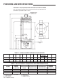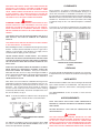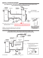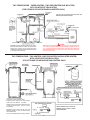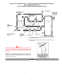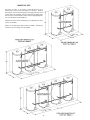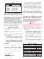
1
COMMERCIAL GAS
Lined Tank Type Water Heater
• Installation • Service • Maintenance
CAUTION
TEXT PRINTED OR OUTLINED IN RED CONTAINS
INFORMATION RELATIVE TO YOUR SAFETY. PLEASE READ
THOROUGHLY BEFORE INSTALLING AND USING THIS
APPLIANCE.
PLACE THESE INSTRUCTIONS ADJACENT TO HEATER AND
NOTIFY OWNER TO KEEP FOR FUTURE REFERENCE.
PRINTED IN U.S.A. 1102
PART NO. 195091-000
1
FEATURES AND SPECIFICATIONS
The illustration shows a typical gas-fired commercial gas power burner, tank-type
water heater. The principal components of the heater are shown and identified
here. By referring to the plate on the heater jacket the unit may be identified in the
specifications presented in Table 1 and 2.
TABLE 1 - NOMINAL MODEL DIMENSIONS AND WEIGHTS
MODELS
***81-140
***81-199
***81-270
***81-370
A
74
74
74
74
3/4
3/4
3/4
3/4
B
65
65
65
65
C
26
26
26
26
3/4
3/4
3/4
3/4
D
6
6
8
8
E
21
21
21
21
3/8
3/8
3/8
3/8
G
27
27
27
27
H
3/4
3/4
3/4
3/4
38
38
38
38
J
85
85
85
85
1/4
1/4
1/4
1/4
GAS APPROX. SHIP.
WT. (LBS.)
ASME STD.
1/2
658 556
1/2
635 545
3/4
632 547
3/4
731 634
1
1
1
1
IN
OUT
1/2
1/2
1/2
1/2
1
1
1
1
1/2
1/2
1/2
1/2
TABLE 2 - MODEL ENERGY CONSUMPTION AND PERFORMANCE DATA
MODELS
***81-140
***81-199
***81-270
***81-370
STORAGE
CAPACITY
U.S. GALLONS
81
81
81
81
Model Designator: Sample ***81-140NEA
*** = Letter designator
81 = Gallon Capacity
140 = 140,000 BTU/HR imput
IMPUT RATING
BTU/HR.
140,000
199,000
270,000
370,000
RECOVERY RATE
GPH@100°F RISE
136
193
262
359
N = Natural Gas
E = 3 Year Warranty
A = ASME Construction
2
RECOVERY RATE
GPH@140°F RISE
97
138
187
256
MAXIMUM
AMPERES
120V, 60Hz, 1Ø
5
5
5
5
FOREWORD
THESE HEATERS MUST NOT BE INSTALLED DIRECTLY ON
COMBUSTIBLE FLOORS.
These designs comply with the latest version of the American
National Standard for Gas Water Heaters, Volume III,
ANSI Z21.10.3 - CSA 4.3.
In addition to these instructions, the equipment shall be installed
in accordance with those installation regulations in force in the
local area where the installation is to be made. These shall be
carefully followed in all cases. Authorities having jurisdiction
should be consulted before installations are made.
Detailed installation diagrams are found in this manual. These
diagrams will serve to provide the installer with a reference for
the materials and methods of piping necessary. It is highly
essential that all water, gas piping and wiring be installed as shown
on the diagrams.
The installation must conform to these instructions and the local
code authority having jurisdiction. In the absence of local codes
the installation must comply with the latest editions of the National
Fuel Gas Code, ANSI Z223.1/NFPA 54 and the National Electric
Code, NFPA 70. The former is available from the Canadian
Standards Association, 8501 Pleasant Valley Road, Cleveland,
OH 44131 and both documents are available from the National
Fire Protection Association, 1 Batterymarch Park, Quincy,
MA 02269.
Particular attention should be given to the installation of
thermometers at the locations indicated on the diagrams as these
are necessary for checking the proper functioning of the heater.
The ***81-140 through ***81-370 models are designed to
operate on either natural or propane gases. HOWEVER, MAKE
SURE the gas on which the heater will operate is the same as
that specified on the heater model and rating plate.
TABLE OF CONTENTS
PAGE
PAGE
FEATURES AND SPECIFICATIONS ...........................................
FOREWORD ...............................................................................
GENERAL SAFETY INFORMATION
Precautions .............................................................................
Chemical Vapor Corrosion ......................................................
Improper Combustion .............................................................
Liquid Petroleum Models .........................................................
Extended Non-Use Periods .....................................................
Insulation Blankets ..................................................................
High Altitude Installation .........................................................
FEATURES
High Limit Switch (E.C.O.) ......................................................
Circulating Pump .....................................................................
Dishwashing Machine Requirements ......................................
INSTALLATION INSTRUCTIONS
Required Ability .......................................................................
Uncrating .................................................................................
Locating the Heater .................................................................
Clearances ..............................................................................
Levelling ..................................................................................
Hard Water ..............................................................................
Air Requirements ....................................................................
Mechanical Exhausting of Room Air .......................................
Venting ....................................................................................
Barometric Draft Control Assembly ........................................
Vent Connection ......................................................................
Drain Valve and Access Panels ..............................................
Burner Installation ...................................................................
Gas Meter Size-City Gases Only ............................................
Gas Pressure Regulation ........................................................
Gas Piping ...............................................................................
2
3
Heater Wiring Instructions ......................................................
Water Line Connection ..........................................................
Water (Potable) Heating and Spacing ..................................
Relief Valve ............................................................................
Thermometers (Not Supplied) ...............................................
Wiring for ***81-140 thru ***81-370 .......................................
INSTALLATION DIAGRAMS ......................................................
Manifold Kits ..........................................................................
PRIOR TO START UP
Required Equipment And Ability ..........................................
Purging ...................................................................................
Water Temperature Control ...................................................
Operation & Adjustment Procedure ......................................
Adjustment Procedure ...........................................................
MAINTENANCE
Maintenance Schedule .........................................................
Flushing ..................................................................................
Draining ..................................................................................
Sediment Removal ................................................................
Lime Scale Removal .............................................................
Relief Valve ...........................................................................
Circulating Pump ...................................................................
Power Burner ..........................................................................
Vent System ............................................................................
Barometric Draft Control ........................................................
Electrical Servicing ................................................................
CHECKLIST AND SERVICE INFORMATION ............................
TROUBLESHOOTING ................................................................
Replacement Parts .................................................................
PARTS LIST ................................................................................
3
3-4
4
4
4
4
4-5
5
5
5
5
5
5-6
6
6
6
6-7
7
7
7
7-8
8
8
8
8-9
9
9-10
10
10
10
10
11
12-15
16
17
17
17
18
19-20
20
20
20
20
20-21
21
21
21
21
21-22
22
22-23
23
23
24-27
GENERAL SAFETY INFORMATION
PRECAUTIONS
3. FIRING WITHOUT WATER.
4 SOOTING.
DO NOT USE THIS APPLIANCE IF ANY PART HAS BEEN
UNDERWATER. Immediately call a qualified service technician
to inspect the appliance and to replace any part of the control
system and any gas control which has been under water.
Heater must be protected from freezing downdrafts during
shutdown periods.
CHEMICAL VAPOR CORROSION
IF THE UNIT IS EXPOSED TO THE FOLLOWING, DO NOT
OPERATE HEATER UNTIL ALL CORRECTIVE STEPS HAVE
BEEN MADE BY A QUALIFIED SERVICEMAN.
WARNING
CORROSION OF THE FLUEWAYS AND VENT SYSTEM MAY
OCCUR IF AIR FOR COMBUSTION CONTAINS CERTAIN
CHEMICAL VAPORS WHICH BREAK DOWN INTO ACIDS AT
HIGH TEMPERATURE. SUCH CORROSION MAY RESULT IN
FAILURE AND RISK OF ASPHYXIATION.
1. EXTERNAL FIRE.
2. DAMAGE.
3
Spray can propellants, cleaning solvents, refrigerator and air
conditioning refrigerants, swimming pool chemicals, calcium
and sodium chloride (water softener salt), waxes, and process
chemicals contain typical compounds which are potentially
corrosive. Do not store products of this sort near the heater.
Also, air which is brought in contact with the heater should not
contain any of these chemicals. If necessary, uncontaminated
air should be obtained from remote or outside sources. The
limited warranty is voided when failure of water heater is due to
a corrosive atmosphere. (Refer to the limited warranty for
complete terms and conditions).
recommended that the hot water faucet be opened for several
minutes at the kitchen sink before using any electrical appliance
connected to the hot water system. If hydrogen is present, there
will probably be an unusual sound such as air escaping through
the pipe as the water begins to flow. THERE SHOULD BE NO
SMOKING OR OPEN FLAME NEAR THE FAUCET AT THE TIME
IT IS OPEN.
INSULATION BLANKETS
Insulation blankets available to the general public for external
use on gas water heaters are not approved for use on your water
heater. The purpose of an insulation blanket is to reduce the
standby heat loss encountered with storage tank water heaters.
Your water heater meets or exceeds the ASHRAE/IES
90.1b-1992 standards with respect to insulation and standby
loss requirements making an insulation blanket unnecessary.
IMPROPER COMBUSTION
WARNING
ATTIC AND/OR EXHAUST FANS OPERATING ON THE PREMISES
WITH A WATER HEATER CAN RESULT IN CARBON MONOXIDE
POISONING AND DEATH.
WARNING
Should you choose to apply an insulation blanket to this heater,
you should follow these instructions. Failure to follow these
instructions can result in fire, asphyxiation, serious personal injury
or death.
OPERATING THESE FANS CAN PRODUCE A NEGATIVE DRAFT
IN THE AREA OF THE WATER HEATER PREVENTING THE
PRODUCTS OF COMBUSTION FROM EXHAUSTING THROUGH
THE CHIMNEY OR VENT PIPE.
The venting of the water heater should be inspected by a qualified
service technician at the time of installation and periodically
thereafter to ensure a down-draft condition does not exist.
• Do not apply insulation to the top of the water heater, as this
will interfere with safe operation of drafthood.
• Do not cover the temperature & pressure relief valve.
DO NOT OBSTRUCT THE FLOW OF COMBUSTION AND
VENTILATING AIR. ADEQUATE AIR FOR COMBUSTION AND
VENTILATION MUST BE PROVIDED FOR SAFE OPERATION.
• Do not cover the instruction manual. Keep it on the side of the
water heater or nearby for future reference.
LIQUID PETROLEUM MODELS
• Do obtain new labels from manufacturer for placement on
the blanket directly over the existing labels.
Water heaters for propane or liquefied petroleum gas (LPG) are
different from natural gas models. A natural gas heater will not
function safely on LP gas and no attempt should be made to
convert a heater from natural gas to LP gas.
HIGH ALTITUDE INSTALLATIONS
WARNING
INSTALLATIONS ABOVE 2000 FEET REQUIRE REPLACEMENT
OF THE BURNER ORIFICE IN ACCORDANCE WITH SECTION
8.1.2 OF THE NATIONAL FUEL GAS CODE (ANSI Z223.1).
FAILURE TO REPLACE THE ORIFICE WILL RESULT IN
IMPROPER AND INEFFICIENT OPERATION OF THE APPLIANCE
RESULTING IN THE PRODUCTION OF INCREASED LEVELS
OF CARBON MONOXIDE GAS IN EXCESS OF SAFE LIMITS
WHICH COULD RESULT IN SERIOUS PERSONAL INJURY OR
DEATH.
LP gas must be used with great caution. It is highly explosive
and heavier than air. It collects first in the low areas making its
odor difficult to detect at nose level. If LP gas is present or even
suspected, do not attempt to find the cause yourself. Go to a
neighbor’s house, leaving your doors open to ventilate the house,
then call your gas supplier or service agent. Keep area clear
until a service call has been made.
At times you may not be able to smell an LP gas leak. One
cause is odor fade, which is a loss of the chemical odorant that
gives LP gas its distinctive smell. Another cause can be your
physical condition, such as having a cold or diminishing sense
of smell with age. For these reasons, the use of a propane gas
detector is recommended.
As elevation above sea level is increased, there is less oxygen
per cubic foot of air. Therefore, the heater input rate should be
reduced at high altitudes for satisfactory operation with the
reduced oxygen supply. Failure to make this reduction would
result in an overfiring of the heater, causing sooting, poor
combustion and/or unsatisfactory heater performance.
Only trained LP professionals should conduct the required safety
checks in accordance with industry standards.
Ratings specified by manufacturers for most appliances apply
for elevations up to 2000 feet. For elevations above 2000 feet,
ratings must be reduced at the rate of 4% for each 1000 feet
above sea level. For example, if a heater is rated at 120,000 Btu/
hr. at sea level, to rate the heater at 4000 feet, you subtract 4
(once for each thousand feet) x .04 (4% input reduction) x 120,000
(the original rating) from the original rating. Therefore, to calculate
the input rating at 4000 feet: 4 x .04 x 120,000 = 19,200 btu/hr.,
120,000 - 19,200 = 100,800 btu/hr. At 6000 feet elevation, the
heater rating would be 91,200 btu/hr.
EXTENDED NON-USE PERIODS
WARNING
HYDROGEN GAS CAN BE PRODUCED IN A HOT WATER
SYSTEM SERVED BY THIS HEATER THAT HAS NOT BEEN USED
FOR A LONG PERIOD OF TIME (GENERALLY TWO WEEKS OR
MORE). HYDROGEN GAS IS EXTREMELY FLAMMABLE. To
reduce the risk of injury under these conditions, it is
4
The input reduction is primarily achieved by reducing the size of
the main burner orifices. To do this, the main burner orifices
require replacement with orifices sized for the particular installation
elevation. Correct orifice sizing and parts may be obtained from
the manufacturer. See the REPLACEMENT PARTS section of
this manual. When ordering, be sure to state the model number
and the altitude of the location where the heater is being
installed.
Refer to the piping diagrams at rear of manual for electrical
hookup information and install in accordance with the latest
version of the National Electric Code ANSI/NFPA No. 70.
Upon completion of derating of the heater, adjustment to the gas
pressure regulator may be required. See ADJUSTMENT
PROCEDURE in this manual for inlet and manifold pressure
requirements.
DISHWASHING MACHINE REQUIREMENT
Only all bronze circulators are used with commercial water heaters.
Although circulators are oiled and operated by the manufacturer
some circulators must be oiled again before operating. Please
refer to manufacturer’s instructions.
All dishwashing machines meeting the National Sanitation
Foundation requirements are designed to operate with water flow
pressures between 15 and 25 pounds per square inch. Flow
pressures above 25 pounds per square inch, or below 15 pounds
per square inch, will result in improperly sanitized dishes. Where
pressures are high, a water pressure reducing or flow regulating
control valve should be used in 1800 line to the dishwashing
machine, and should be adjusted to deliver water between these
limits.
Also, due to the input rating reduction required at high altitudes,
the output rating of the appliance is also reduced and should be
compensated for in the sizing of the equipment for applications.
FEATURES
The National Sanitation Foundation also recommends circulation
of 1800F water. Where this is done, the circulation should be
very gentle so that it does not cause any unnecessary turbulence
inside the water heater. The circulation should be just enough to
provide 1800F water at the point of take-off to the dishwashing
machine. Adjust flow by means of the plug cock in the circulating
line.
HIGH LIMIT SWITCH (E.C.O.)
The dual bulb controller ((fig. 1) contains the high limit (energy
cutoff) sensor. The high limit switch interrupts main burner gas
flow should the water temperature reach 205°F (96°C).
In the event of high limit switch operation, the appliance cannot
be restarted unless the water temperature is reduced by at least
20°F (11°C) and the high limit reset button on front of limit control
(fig.1) is depressed.
INSTALLATION INSTRUCTIONS
REQUIRED ABILITY
INSTALLATION OR SERVICE OF THIS WATER HEATER
REQUIRES ABILITY EQUIVALENT TO THAT OF A LICENSED
TRADESMAN IN THE FIELD INVOLVED. PLUMBING, AIR
SUPPLY, VENTING, GAS SUPPLY AND ELECTRICAL WORK
ARE REQUIRED.
UNCRATING
Uncrate the heater by removing the outside mat and top locator.
The shipping pallet must be removed from the unit. It may be
possible to simply unbolt the base from the pallet and, with the
help of 2 or more persons, work the unit off the pallet. Some
units will be too heavy and will require the use of jacks or lifting
equipment to safely remove the pallet and move the unit into
position. Be careful when moving this heater. It will tip over
easily.
DUAL-BULB THERMOSTAT (COVER REMOVED)
FIGURE 1
Continued manual resetting of high limit control, preceded by
higher than usual water temperature is evidence of high limit switch
operation. The following is a possible reason for high limit switch
operation.
The heater is shipped with a burner and draft control. The burner
and draft control are shipped in separate cartons. They should
be installed as received without any alterations.
• A malfunction in the thermostatic controls would allow the gas
valve to remain open causing water temperature to exceed
the thermostat setting. The water temperature would continue
to rise until high limit switch operation.
Discard the shipping crate and packaging cartons in an appropriate
manner.
LOCATING THE HEATER
Contact your dealer or servicer if continued high limit switch
operation occurs, to determine the reason for operation.
WARNING
THERE IS A RISK IN USING FUEL BURNING APPLIANCES
SUCH AS GAS WATER HEATERS IN ROOMS, GARAGES OR
OTHER AREAS WHERE GASOLINE, OTHER FLAMMABLE
LIQUIDS OR ENGINE DRIVEN EQUIPMENT OR VEHICLES ARE
STORED, OPERATED OR REPAIRED. FLAMMABLE VAPORS
CIRCULATING PUMP
A circulating pump is used when a system requires a circulating
loop or there is a storage tank used in conjunction with the heater.
5
ARE HEAVY AND TRAVEL ALONG THE FLOOR AND MAY BE
IGNITED BY THE HEATER’S IGNITION SYSTEM OR MAIN
BURNER FLAMES CAUSING FIRE OR EXPLOSION. SOME
LOCAL CODES PERMIT OPERATION OF GAS APPLIANCES
IN SUCH AREAS IF THEY ARE INSTALLED 18 INCHES OR
MORE ABOVE THE FLOOR. THIS MAY REDUCE THE RISK IF
LOCATION IN SUCH AN AREA CANNOT BE AVOIDED.
CLEARANCES
These heaters are design certified by the Underwriter’s
Laboratories for installation on non-combustible flooring in an
alcove with clearances to combustible construction of 6" from
the sides and rear, and 6" minimum between vent pipe and ceiling.
Minimum clearance from barometric draft control to combustible
material is 6". A minimum of 21" from top of heater to the ceiling
is required, except for the ***81-370 which requires a minimum
of 24".
WARNING
FLAMMABLE ITEMS, PRESSURIZED CONTAINERS OR ANY
OTHER POTENTIAL FIRE HAZARDOUS ARTICLES MUST
NEVER BE PLACED ON OR ADJACENT TO THE HEATER.
OPEN CONTAINERS OF FLAMMABLE MATERIAL SHOULD
NOT BE STORED OR USED IN THE SAME ROOM WITH THE
HEATER.
A clearance of 24" shall be maintained from serviceable parts,
such as the relief valve, power burner, thermostat and drain valve.
THE HEATER SHALL BE LOCATED OR PROTECTED SO IT IS
NOT SUBJECT TO PHYSICAL DAMAGE BY A MOVING
VEHICLE.
THE HEATER MUST NOT BE LOCATED IN AN AREA WHERE
IT WILL BE SUBJECT TO FREEZING.
When installing the heater, consideration must be given to proper
location. Location selected should be as close to a gas vent or
chimney as practicable, with adequate air supply and as
centralized with the piping system as possible.
LOCATE HEATER NEAR A FLOOR DRAIN. THE HEATER
SHOULD BE LOCATED IN AN AREA WHERE LEAKAGE FROM
THE TANK OR CONNECTIONS WILL NOT RESULT IN DAMAGE
TO THE ADJACENT AREA OR TO LOWER FLOORS OF THE
STRUCTURE.
PROPER INSTALLATION CLEARANCES
FIGURE 3
WHEN SUCH LOCATIONS CANNOT BE AVOIDED, A SUITABLE
METAL DRAIN PAN, ADEQUATELY DRAINED, SHOULD BE
INSTALLED UNDER THE HEATER. Such pans should be
fabricated with sides at least 2" deep, with length and width at
least 2" greater than the diameter of the heater and must be piped
to an adequate drain. THE PAN MUST NOT RESTRICT
COMBUSTION AIR FLOW.
LEVELLING
The heater shall be installed plumb to the ground. If it is necessary
to adjust the heater, use metal shims under the channel type skid
base.
HARD WATER
Units which are to be installed on combustible flooring must be
supported by a full layer of hollow concrete blocks, from 8" to 12"
thick and extending 12" (minimum) beyond the heater in all
directions. The concrete blocks must provide an unbroken
concrete surface under the heater with the hollows running
continuously and horizontally. A 3/16 inch steel plate must cover
the concrete blocks, see fig. 2.
Where hard water conditions exist, water softening or the threshold
type of water treatment is recommended. This will protect the
dishwashers, coffee urns, water heaters, water piping and other
equipment.
See MAINTENANCE section for details of tank cleanout
procedures.
NOTE: If electrical conduits run under the floor of the proposed
heater location, insulate the floor asrecommended
above.
AIR REQUIREMENTS
KEEP APPLIANCE AREA FREE FROM COMBUSTIBLE
MATERIALS, GASOLINE AND OTHER FLAMMABLE VAPORS
AND LIQUIDS.
DO NOT OBSTRUCT THE FLOW OF COMBUSTION OR
VENTILATING AIR.
WARNING
FOR SAFE OPERATION PROVIDE ADEQUATE AIR FOR
COMBUSTION AND VENTILATION. AN INSUFFICIENT SUPPLY
OF AIR WILL CAUSE RECIRCULATION OF COMBUSTION
PRODUCTS RESULTING IN AIR CONTAMINATION THAT MAY
BE HAZARDOUS TO LIFE. SUCH A CONDITION OFTEN WILL
RESULT IN A YELLOW, LUMINOUS BURNER FLAME, CAUSING
PROPER INSTALLATION ON COMBUSTIBLE FLOORING
FIGURE 2
For appliance installation locations with elevations above 2000
feet, refer to HIGH ALTITUDE INSTALLATIONS section of this
manual for input reduction procedure.
6
CARBONING OR SOOTING OF THE COMBUSTION CHAMBER,
BURNERS AND FLUE TUBES AND CREATES A RISK OF
ASPHYXIATION.
figure 4. The outlet of the draft control assembly may be rotated
to face in direction needed. The assembly must be fitted to the
jacket cover such that it is plumb and level to the ground. Fasten
the draft control assembly to the top cover using sheet metal
screws at three locations, or more, as required.
MECHANICAL EXHAUSTING OF ROOM AIR
Dampers or other obstructions must not be installed between the
heater and the barometric draft control assembly.
Where an exhaust fan is installed in the same room with a heater,
sufficient openings for air must be provided in the walls.
UNDERSIZED OPENINGS WILL CAUSE AIR TO BE DRAWN
INTO THE ROOM THROUGH THE CHIMNEY, CAUSING POOR
COMBUSTION. SOOTING MAY RESULT IN SERIOUS DAMAGE
TO THE HEATER AND RISK OF FIRE OR EXPLOSION.
Do not adjust settings on gate. Counterweight washers are factory
adjusted and should result in breeching pressure measurements
at the combustion test hole (fig. 4) within the range shown in
table 6.
UNCONFINED SPACE
NOTE: A negative draft must be maintained in the vent piping.
In buildings of conventional frame, brick or stone construction,
unconfined spaces may provide adequate air for combustion,
ventilation, and draft hood dilution.
When installed, the damper gate must pivot freely in the ring
guides. This gate will automatically adjust to regulate the chimney
draft imposed on the heater.
If the unconfined space is within a building of tight construction
(buildings using the following construction: weather stripping,
heavy insulation, caulking, vapor barrier, etc.), air for combustion,
ventilation and draft hood dilution must be obtained from outdoors.
The installation instructions for confined spaces in tightly
constructed buildings must be followed to ensure adequate air
supply.
CONFINED SPACE
When drawing combustion and dilution air from inside a
conventionally constructed building to a confined space, such a
space shall be provided with two permanent openings, ONE IN
OR WITHIN 12 INCHES OF THE ENCLOSURE TOP AND ONE
IN OR WITHIN 12 INCHES OF THE ENCLOSURE BOTTOM.
Each opening shall have a free area of at least one square inch
per 1000 Btuh of the total input of all appliances in the enclosure,
but not less than 100 square inches.
PROPER DRAFT CONTROLLER AND
VENT PIPE INSTALLATION
FIGURE 4
VENT CONNECTION
If the confined space is within a building of tight construction, air
for combustion, ventilation and draft hood dilution must be
obtained from outdoors. When directly communicating with the
outdoors through vertical ducts, two permanent openings, located
in the above manner, shall be provided. Each opening shall have
a free area of not less than one square inch per 4000 Btuh of the
total input of all appliances in the enclosure. If horizontal ducts
are used, each opening shall have a free area of not less than
one square inch per 2000 Btuh of the total input of all appliances
in the enclosure.
Vent connections must be made to an adequate stack or chimney.
Refer to the National Fuel Gas Code (latest version) or to the
vent pipe manufacturer’s gas vent and chimney sizing table to
properly design and size the venting system. Refer to Table 3 for
the vent pipe size required for installation to the barometric draft
control assembly outlet.
TABLE 3 - BAROMETRIC DRAFT CONTROL
ASSEMBLY OUTLET SIZE
VENTING
MODEL
***81-140
***81-199
***81-270
***81-370
WARNING
THE INSTRUCTIONS IN THIS SECTION ON VENTING MUST
BE FOLLOWED TO AVOID CHOKED COMBUSTION OR
RECIRCULATION OF FLUE GASES. SUCH CONDITIONS
CAUSE SOOTING OR RISKS OF FIRE AND ASPHYXIATION.
DRAFT CONTROL
OUTLET DIAMETER
6”
6”
8”
8”
Where an existing chimney or vent is to be used, be sure that the
chimney or vent has adequate capacity for the number and sizes
of gas appliances being vented through it. Inspect the chimney
or vent and remove all soot or other obstructions which will retard
free draft.
Type B venting may be used with these heaters. All local and
utility regulations on venting should be followed.
BAROMETRIC DRAFT CONTROL ASSEMBLY
Vent connectors making horizontal runs must have a minimum
upward slope toward the chimney or vent of 1/4 inch per foot.
Vent connector length should be kept as short as possible. Be
sure that the vent pipe does not extend beyond the inside wall of
a chimney.
A double-acting barometric draft control assembly is provided with
each unit. The draft control assembly must be installed without
alteration. This assembly is factory adjusted for horizontal
application only and must be attached to the heater as shown in
7
Occasionally, some water seepage will occur at a cleanout port.
To correct this situation, slightly tighten the cleanout cover bolts
until the seepage is eliminated. Do not overly tighten the bolts or
the cleanout gasket will be damaged. Tighten each bolt gradually
and alternate between opposed bolts on the cleanout cover.
In venting systems where a continuous or intermittent back
(positive) draft is found to exist, the cause must be determined
and corrected. In some cases, a special vent cap may be
required.
Do not install this unit on the positive draft side of a venting system
being served by a power exhauster.
BURNER INSTALLATION
DRAIN VALVE AND ACCESS PANELS
Remove the factory-installed insulation covering the combustion
chamber opening. (A utility knife is useful for cutting out the
insulation). Cut the insulation back even with the jacket opening.
Install the flange gasket (which is usually taped to the heater
jacket) over the three bolts protruding from the tank at the
combustion chamber opening.
The heaters are equipped with a 3/4" drain valve mounted above
and to the left of the burner. See page 2.
The combustion chamber observation access panel is located
above and to the left of the burner. A plug located under the
panel, see fig. 5, is inserted into the combustion chamber wall.
This plug should not be removed except, in rare cases, when the
combustion chamber requires cleaning or replacement.
Remove the hardware (3 hex nuts, 3 flat washers, and 3 lock
washers) from the shipping bag attached to the heater’s electrical
conduit.
WARNING
DO NOT REMOVE THIS PLUG WHILE THE HEATER IS IN
OPERATION. THE COMBUSTION CHAMBER IS UNDER
PRESSURE AND MAIN BURNER FLAMES WILL ESCAPE
THROUGH THE OPENING. THIS IS AN EXTREMELY
HAZARDOUS CONDITION WHICH MAY RESULT IN SERIOUS
INJURY.
POWER BURNER INSTALLATION
FIGURE 7
COMBUSTION CHAMBER ACCESS PORT
FIGURE 5
Begin assembling the power burner to the tank by placing the
power burner nozzle in the combustion chamber opening. Slide
the nozzle into the tank and rotate the mounting flange to engage
the mounting bolts, refer to Figure 7. Then, place the flat washers
followed by the lock washers, and finally the hex nuts on the
mounting bolts. Hand tighten the nuts. Then gradually tighten
each nut alternating between the 3 mounting bolts. Do not over
tighten as damage to the flange gasket or to the tank may result.
Refer to figure 7.
IMPORTANT
Before removing the access panel and observation plug, BE SURE
THAT THE ELECTRICAL POWER TO THE HEATER IS “OFF”.
This will prevent the heater from operating while servicing the
unit. Remember to install the plug and access cover BEFORE
restoring electrical power to the heater.
Another access panel is located above and to the right of the
burner, fig. 6. This panel covers the cleanout opening in the tank
which is sealed by a gasket and cover.
GAS METER SIZE — CITY GASES ONLY
Be sure that the gas meter has sufficient capacity to supply the
full-rated gas input of the water heater as well as the
requirements of all other gas fired equipment supplied by the
meter. If gas meter is too small, request the gas company to
install a larger meter having adequate capacity.
GAS PRESSURE REGULATION
Main manual pressure to the water heater should be between
4.5" minimum and 10.5" maximum w.c. for natural gas and 11.0"
minimum and 13.0" maximum w.c. for propane gas. The inlet
gas pressure must not exceed the maximum value. A service
regulator is necessary if higher gas pressures are encountered.
See Table 6.
TANK CLEANOUT PORT
FIGURE 6
8
TABLE 4
MAXIMUM CAPACITY OF PIPE IN CUBIC FEET
OF GAS PER HOUR
WARNING
THE HEATER IS NOT INTENDED FOR OPERATION AT HIGHER
THAN 10.5" W.C. - NATURAL GAS, 13.0" W.C. - PROPANE GAS
(1/2 POUND PER SQUARE INCH GAUGE) SUPPLY GAS
PRESSURE. HIGHER GAS PRESSURES REQUIRE
SUPPLEMENTAL REDUCING SERVICE REGULATION.
EXPOSURE TO HIGHER GAS SUPPLY PRESSURE MAY CAUSE
DAMAGE TO THE GAS CONTROLS WHICH COULD RESULT IN
FIRE OR EXPLOSION. IF OVERPRESSURE HAS OCCURRED,
SUCH AS THROUGH IMPROPER TESTING OF GAS LINES OR
EMERGENCY MALFUNCTION OF THE SUPPLY SYSTEM, THE
GAS VALVE MUST BE CHECKED FOR SAFE OPERATION. MAKE
SURE THAT THE OUTSIDE VENTS ON THE SUPPLY
REGULATORS AND THE SAFETY VENT VALVES ARE
PROTECTED AGAINST BLOCKAGE. THESE ARE PARTS OF
THE GAS SUPPLY SYSTEM, NOT THE HEATER. VENT
BLOCKAGE MAY OCCUR DURING ICE STORMS.
(Based upon a Pressure Drop of 0.5 inch Water Column and
0.6 Specific Gravity Gas and max. gas pressure of .5 psig)
LENGTH
IN FEET 1/2
10
175
20
120
30
97
40
82
50
73
60
66
70
61
80
57
90
53
100
50
125
44
150
40
175
37
200
35
DISCONNECT THE APPLIANCE AND ITS MAIN MANUAL GAS
SHUTOFF VALVE FROM THE GAS SUPPLY PIPING SYSTEM
DURING ANY SUPPLY PRESSURE TESTING EXCEEDING 1/2
PSIG. GAS SUPPLY LINE MUST BE CAPPED WHEN
DISCONNECTED FROM THE HEATER. FOR TEST
PRESSURES OF 1/2 PSIG OR LESS, THE APPLIANCE NEED
NOT BE DISCONNECTED, BUT MUST BE ISOLATED FROM
THE SUPPLY PRESSURE TESTING BY CLOSING THE MAIN
MANUAL GAS SHUT OFF VALVE.
3/4
360
250
200
170
151
138
125
118
110
103
93
84
77
72
NOMINAL IRON PIPE SIZE (INCHES)
1 1 1/4 1 1/2
2
2 1/2
3
680 1,400 2,100 3,950 6,300 11,000
465 950 1,460 2,750 4,350 7,700
375 770 1,180 2,200 3,520 6,250
320 660 990 1,900 3,000 5,300
285 580 900 1,680 2,650 4,750
260 530 810 1,520 2,400 4,300
240 490 750 1,400 2,250 3,900
220 460 690 1,300 2,050 3,700
205 430 650 1,220 1,950 3,450
195 400 620 1,150 1,850 3,250
175 360 550 1,020 1,650 2,950
160 325 500 950 1,500 2,650
145 300 460 850 1,370 2,450
135 280 430 800 1,280 2,280
4
23,000
15,800
12,800
10,900
9,700
8,800
8,100
7,500
7,200
6,700
6,000
5,500
5,000
4,600
Apply joint compounds (pipe dope) sparingly and only to the male
threads of pipe joints. Do not apply compound to the first two
threads. Use joint compounds resistant to the action of liquefied
petroleum gases.
BEFORE PLACING THE HEATER IN OPERATION, CHECK FOR
GAS LEAKAGE. USE SOAP AND WATER SOLUTION, OR
OTHER MATERIAL ACCEPTABLE FOR THE PURPOSE IN
LOCATING GAS LEAKS. DO NOT USE MATCHES, CANDLES,
FLAME OR OTHER SOURCES OF IGNITION FOR THIS
PURPOSE.
GAS PIPING
Contact your local gas service company to ensure that adequate
gas service is available and to review applicable installation
codes for your area.
Size the main gas line in accordance with Table 4. The figures
shown are for iron pipe or equivalent at 0.5 in. w.c. pressure
drop, which is considered normal for low pressure systems.
Note that an excess number of fittings such as elbows and tees
will add to the pipe pressure drop. No additional allowance is
necessary for an ordinary number of fittings.
IF COPPER SUPPLY LINES ARE USED THEY MUST BE
INTERNALLY TINNED AND CERTIFIED FOR GAS SERVICE.
IT IS IMPORTANT TO GUARD AGAINST GAS VALVE FOULING
FROM CONTAMINANTS IN THE GAS WAYS. SUCH FOULING
MAY CAUSE IMPROPER OPERATION, FIRE OR EXPLOSION.
POWER BURNER ASSEMBLY, GAS MANIFOLD AND SUGGESTED
INLET PIPING - FIGURE 8
BEFORE ATTACHING THE GAS LINE, BE SURE THAT ALL GAS
PIPE IS CLEAN ON THE INSIDE.
HEATER WIRING INSTRUCTIONS
TO TRAP ANY DIRT OR FOREIGN MATERIAL IN THE GAS
SUPPLY LINE, A DRIP LEG (SOMETIMES CALLED DIRT LEG)
MUST BE INCORPORATED IN THE PIPING. SEE FIG. 8. THE
DRIP LEG MUST BE READILY ACCESSIBLE, REFER TO FIG. 8,
AND NOT SUBJECT TO FREEZING CONDITIONS. INSTALL IN
ACCORDANCE WITH RECOMMENDATIONS OF SERVICING
GAS SUPPLIERS. REFER TO THE NATIONAL FUEL GAS CODE
(LATEST VERSION).
The power burner should be wired to the heater as shown in
Figure 9. The model’s rating plate (or see Table 2) provides the
electrical information needed to size the complete heater branch
supply circuit.
All electrical work must be installed in accordance with the latest
version of the National Electrical Code and local requirements.
When installed, the appliance must be electrically grounded in
accordance with local codes or, in the absence of local codes,
with the latest version of the National Electrical Code,
ANSI/NFPA 70.
To prevent damage, care must be taken not to apply too much
torque when attaching gas supply pipe to gas valve inlet.
9
With the power burner installed in the heater, the electrical wiring
can be completed. On ***81-140 and ***81-199 models, remove
the power burner backplate and fasten the conduit assembly to
the power burner assembly. Next, connect the black wire to the
terminal marked “1” and the white wire to the terminal
marked “2”.
to installation diagrams on pages 12-16 of this manual for
suggested piping arrangements.
CAUTION
A closed system will exist if a check valve (without bypass),
pressure reducing valve (without bypass), or a water meter
(without bypass) is installed in the cold water line between the
water heater and street main (well).
On ***81-270 and ***81-370 models, remove the two screws
above and below the control board on the junction box cover of
the power burner. Swing the junction box cover open and fasten
the conduit assembly in one of the knock-out holes in the side of
the junction box. Connect the black wire to the terminal marked
“1” and the white wire to the terminal marked “2”.
Excessive pressure may develope in such closed systems,
causing premature tank failure or intermittent relief valve operation.
This is not a warranty failure. An expansion tank or similar device
may be required in the inlet supply line between the appliance
and the meter or valve to compensate for the thermal expansion
of the water.
Finally, bring electrical power to the junction box mounted on the
heater jacket. Fasten conduit to any convenient knock-out hole
in the junction box. Use the two wire nuts from the shipping bag
to connect the hot and neutral conductors to the black and white
wires, respectively. Connect the ground conductor to the ground
screw in the back of the junction box.
SYSTEM CONNECTIONS
The system installation must conform to these instructions and
to the local code authority having jurisdiction. Good practice
requires that all heavy piping be supported.
Check all electrical connections to be sure that they are proper
and secure.
RELIEF VALVE
DO NOT ENERGIZE THE BRANCH CIRCUIT BEFORE THE
HEATER TANK IS FILLED WITH WATER.
This heater is equipped with an approved temperature and
pressure relief valve. ASME ratings cover pressure relief. A.G.A.
ratings cover release rate with temperature actuation.
WATER LINE CONNECTION
This manual provides detailed installation diagrams (see pages
12-16) of this manual for typical methods of application for the
water heaters.
Your local code authority may have other specific relief valve
requirements.
The water heater may be installed itself, or with a separate storage
tank, on both single and two-temperature systems. When used
with a separate storage tank, the circulation may be either by
gravity or by means of a circulating pump. When a circulating
pump is used it is important to note that the flow rate should be
slow so that there will be a minimum of turbulence inside the
heater.
WARNING
THE PURPOSE OF RELIEF VALVE IS TO AVOID EXCESSIVE
PRESSURE OF TEMPERATURE INTO THE STEAM RANGE,
WHICH MAY CAUSE SCALDING AT FIXTURES, TANK
EXPLOSION, SYSTEM OR HEATER DAMAGE. NO VALVE IS
TO BE PLACED BETWEEN THE RELIEF VALVE AND THE
TANK.
If a water heater is installed in a closed water system, contact the
water supplier or local plumbing inspector on how to control this
situation.
A DRAIN LINE MUST BE CONNECTED TO THE RELIEF VALVE
TO DIRECT DISCHARGE TO A SAFE LOCATION TO AVOID
SCALDING OR WATER DAMAGE. THIS LINE MUST NOT BE
REDUCED FROM THE SIZE OF THE VALVE OUTLET AND
MUST NOT CONTAIN VALVES, RESTRICTIONS NOR SHOULD
IT BE LOCATED IN FREEZING AREAS. DO NOT THREAD OR
CAP THE END OF THIS LINE. RESTRICTED OR BLOCKED
DISCHARGE WILL DEFEAT THE PURPOSE OF THE VALVE
AND IS UNSAFE. INSTALL DISCHARGE LINE TO ALLOW
COMPLETE DRAINAGE OF BOTH THE VALVE AND LINE.
WATER (POTABLE) HEATING AND SPACE
HEATING (See pages 12-16)
1. All piping components connected to this unit for space heating
applications shall be suitable for use with potable water.
2. Toxic chemicals, such as those used for boiler treatment, shall
NEVER be introduced into this system.
THERMOMETERS (Not Supplied)
3. This unit may NEVER be connected to any existing heating
system or component(s) previously used with a non-potable
water heating appliance.
Thermometers should be obtained and field installed as shown
in the installation diagrams.
4. When the system requires water for space heating at
temperatures higher than required for domestic water
purposes, a tempering valve must be installed. Please refer
Thermometers are installed in the system as a means of detecting
the temperature of the outlet water supply.
10
SCHEMATIC DIAGRAM
WIRING DIAGRAM
WIRING FOR ***81-140 THRU ***81-370
FIGURE 9
11
INSTALLATION DIAGRAMS
ONE TEMPERATURE - ONE HEATER VERTICAL STORAGE TANK FORCED CIRCULATION
WITH OR WITHOUT BUILDING RECIRCULATION
SCALD PREVENTION
HOT WATER CAN SCALD IF USED
CARELESSLY OR IN UNANTICIPATED
MANNER.
NOTE:CONNECT RETURN LINE FROM HOT
WATER CIRCULATING LOOP (IF USED) TO
COLD WATER INLET LINE.
DANGER
TEMPERATURE SETTING SHOULD NOT EXCEED SAFE USE
TEMPERATURE AT FIXTURES. SEE WATER TEMPERATURE CONTROL
SECTION ON PAGE 17 & 19. IF HIGHER PREHEAT TEMPERATURES
ARE NECESSARY TO OBTAIN ADEQUATE BOOSTER OUTPUT, ADD
AN ANTI-SCALD VALVE FOR HOT WATER SUPPLIED TO FIXTURES.
CAUTION: IF BUILDING COLD WATER SUPPLY HAS A BACK-FLOW
PREVENTER, CHECK VALVE OR WATER METER WITH CHECK VALVE,
PROVISIONS FOR THERMAL EXPANSION OF WATER IN THE HOT WATER
SYSTEM MUST BE PROVIDED.
ONE TEMPERATURE - ONE HEATER HORIZONTAL STORAGE TANK
FORCED CIRCULATION WITH OR WITHOUT BUILDING RECIRCULATION
NOTE:CONNECT RETURN LINE FROM HOT
WATER CIRCULATING LOOP (IF USED) TO
COLD WATER INLET LINE.
WIRING DIAGRAM FOR HEATER TO TANK
LOOP AND/OR HOT WATER LOOP
(IF USED)
*PIPE TO OPEN DRAIN
INSTALL IN ACCORDANCE WITH LOCAL CODES
12
ONE OR TWO TEMPERATURE - ONE HEATER MEDIUM TEMPERATURE STORAGE
WITH OR WITHOUT RECIRCULATION
(FOR STORAGE OR INSTANTANEOUS HEATERS ONLY)
*PIPE RELIEF VALVE TO OPEN DRAIN
NOTE:IF TEMPERED WATER IS
RECIRCULATED, RETURN LINE
SHOULD BE CONNECTED AT POINT “A”.
INSTALL IN ACCORDANCE WITH LOCAL
CODES.
DANGER
TEMPERATURE SETTING SHOULD NOT EXCEED
SAFE USE TEMPERATURE AT FIXTURES. SEE
WATER TEMPERATURE CONTROL SECTION ON
PAGE 17 & 19.
IF HIGHER PREHEAT
TEMPERATURES ARE NECESSARY TO OBTAIN
ADEQUATE BOOSTER OUTPUT, ADD AN ANTISCALD VALVE FOR HOT WATER SUPPLIED TO
FIXTURES.
TWO TEMPERATURE - TWO PRE-HEATERS HIGH TEMPERATURE STORAGE
WITH OR WITHOUT RECIRCULATION
(FOR STORAGE OR INSTANTANEOUS HEATERS ONLY)
CAUTION: IF BUILDING COLD WATER SUPPLY HAS A BACK-FLOW
PREVENTER, CHECK VALVE OR WATER METER WITH CHECK
VALVE, PROVISIONS FOR THERMAL EXPANSION OF WATER IN
THE HOT WATER SYSTEM MUST BE PROVIDED.
13
TWO TEMPERATURE - THREE HEATERS (TWO PRE-HEATERS/ONE BOOSTER)
WITH OR WITHOUT CIRCULATION
(FOR STORAGE OR INSTANTANEOUS HEATERS ONLY)
FOR MULTIPLE HEATER INSTALLATION SEE
MANIFOLD KIT SPECIFICATIONS.
CAUTION: IF BUILDING COLD WATER SUPPLY HAS A
BACK-FLOW PREVENTER, CHECK VALVE OR WATER
METER WITH CHECK VALVE, PROVISIONS FOR
THERMAL EXPANSION OF WATER IN THE HOT WATER
SYSTEM MUST BE PROVIDED.
DANGER
TEMPERATURE SETTING SHOULD NOT EXCEED SAFE USE TEMPERATURE
AT FIXTURES. SEE WATER TEMPERATURE CONTROL SECTION ON PAGE 17
& 19. IF HIGHER PREHEAT TEMPERATURES ARE NECESSARY TO OBTAIN
ADEQUATE BOOSTER OUTPUT, ADD AN ANTI-SCALD VALVE FOR HOT WATER
SUPPLIED TO FIXTURES.
TWO TEMPERATURE - TWO HEATERS (ONE PRE-HEATER/ONE BOOSTER HEATER)
WITH OR WITHOUT RECIRCULATION
(FOR STORAGE OR INSTANTANEOUS HEATERS ONLY)
* PIPE RELIEF VALVE TO OPEN DRAIN.
** TEMPERATURE SETTING OF PRE-HEATER
SHOULD BE 120°F MIN. OR 150°F MAX.
CONNECT CIRCULATING LINE FROM FIXTURES,
IF USED, TO COLD WATER SUPPLY LINE OF
PRE-HEATER.
WIRING DIAGRAM FOR FIXTURE OR
BOOSTER LOOP (IF USED) - OTHER
THAN DISHWASHER
CONNECT CIRCULATING LINE OF 180°F OR
BOOSTED WATER, IF USED, TO INLET WATER
LINE TO BOOSTER.
INSTALL IN ACCORDANCE WITH LOCAL CODES.
14
ONE OR TWO TEMPERATURE - ONE HEATER MEDIUM TEMPERATURE STORAGE
WITH RECIRCULATED LOOP
(FOR STORAGE OR INSTANTANEOUS HEATERS ONLY)
NOTE:IF TEMPERED WATER IS RECIRCULATED, RETURN LINE SHOULD BE
CONNECTED AT POINT “A”.
NOTE:STORED TEMPERATURE WATER LOOP, IF USED, CONNECT TO COLD
WATER INLET.
DANGER
TEMPERATURE SETTING SHOULD NOT EXCEED SAFE USE TEMPERATURE AT
FIXTURES. SEE WATER TEMPERATURE CONTROL SECTION ON PAGE 17 & 19.
IF HIGHER PREHEAT TEMPERATURES ARE NECESSARY TO OBTAIN ADEQUATE
BOOSTER OUTPUT, ADD AN ANTI-SCALD VALVE FOR HOT WATER SUPPLIED
TO FIXTURES.
CAUTION: IF BUILDING COLD WATER SUPPLY HAS A BACK-FLOW
PREVENTER, CHECK VALVE OR WATER METER WITH CHECK VALVE,
PROVISIONS FOR THERMAL EXPANSION OF WATER IN THE HOT WATER
SYSTEM MUST BE PROVIDED.
NOTES
15
MANIFOLD KITS
Precision cut type “L” all copper manifold kits from your
manufacturer assure water flow balance of all units. Without
this balance, the full water heating and storage potential of the
system cannot be achieved. Plus, the units with the higher water
flow may have a shortened life. Unions shown in piping diagrams
are not included in the manifold kits.
Dimensions shown are for minimum space occupied by the water
heaters assemblies.
Space for the barometric draft control assemblies, combustion
clearances and servicing must be added.
16
• Drill max. 5/16" hole in breeching as close as possible to flue
connection on heater to install stack thermometer and
combustion analyzing equipment. (See fig. 4).
PRIOR TO START UP
IMPORTANT
• You are now ready to begin the burner start up procedure.
IT IS REQUIRED THAT A QUALIFIED PERSON PERFORM THE
INITIAL FIRING OF THE HEATER. AT THIS TIME THE USER
SHOULD NOT HESITATE TO ASK THE INDIVIDUAL ANY
QUESTIONS WHICH HE MAY HAVE IN REGARD TO THE
OPERATION AND MAINTENANCE OF THE UNIT.
Follow the OPERATIONAL PROCEDURE in the OPERATIONAL
AND ADJUSTMENT PROCEDURE section of this manual.
PURGING
Gas line purging is required with new piping or systems in which
air has entered.
A CHECKLIST AND SERVICE INFORMATION section is included
at the rear of this manual. By using this checklist the user may
be able to make minor operational adjustments and save himself
unnecessary service calls. However, the user should not attempt
repairs which are not listed in this section.
CAUTION
PURGING SHOULD BE PERFORMED BY PERSONS
EXPERIENCED IN THIS TYPE GAS SERVICE. TO AVOID RISK
OF FIRE OR EXPLOSION, PURGE DISCHARGE MUST NOT
ENTER CONFINED AREAS OR SPACES WHERE IGNITION
CAN OCCUR. THE AREA MUST BE WELL VENTILATED AND
ALL SOURCES OF IGNITION MUST BE INACTIVATED OR
REMOVED.
REQUIRED EQUIPMENT AND ABILITY
INSTALLATION OR SERVICE OF THIS WATER HEATER
REQUIRES ABILITY EQUIVALENT TO THAT OF A LICENSED
TRADESMAN IN THE FIELD INVOLVED. PLUMBING, AIR
SUPPLY, VENTING, GAS SUPPLY AND ELECTRICAL WORK
ARE REQUIRED.
WATER TEMPERATURE CONTROL
Before attempting start-up, thoroughly study and familiarize
yourself with the exact sequence of operation and all other details
on the specific heater being used.
The power burner is equipped with a direct spark ignition system
and automatically sequences prepurge and ignition, senses and
ignites main burner flame and sequences burner operation.
Heater is equipped with an ignition module which locks out after
an unsuccessful ignition attempt. Turn off electric power for ten
seconds before restarting.
Be certain that water heater is full of water, that air is purged from
all lines, no leaks (gas and water) and all inlet water lines are
open.
DANGER
THIS WATER HEATER IS EQUIPPED WITH AN ADJUSTABLE
THERMOSTAT TO CONTROL WATER TEMPERATURE. HOT
WATER TEMPERATURES REQUIRED FOR AUTOMATIC
DISHWASHER AND LAUNDRY USE CAN CAUSE SCALD
BURNS RESULTING IN SERIOUS PERSONAL INJURY AND/
OR DEATH. THE TEMPERATURE AT WHICH INJURY OCCURS
VARIES WITH THE PERSON’S AGE AND TIME OF EXPOSURE.
THE SLOWER RESPONSE TIME OF CHILDREN, AGED OR
DISABLED PERSONS INCREASES THE HAZARDS TO THEM.
NEVER ALLOW SMALL CHILDREN TO USE A HOT WATER TAP,
OR TO DRAW THEIR OWN BATH WATER. NEVER LEAVE A
CHILD OR DISABLED PERSON UNATTENDED IN A BATHTUB
OR SHOWER.
The following test equipment should be on hand: (all test
equipment must be acclimated to ambient temperature before
calibration and use.)
–
CO2 indicator (Fyrite or similar) or O2 analyzer
–
CO indicator (Monoxor or similar)
–
Stack thermometer
–
Draft Gauge or inclined manometer
–
Two U-tube manometers or calibrated 0-10" and 0-35"
w.c. pressure gauges.
–
Combination volt/ammeter.
THE WATER HEATER SHOULD BE LOCATED IN AN AREA
WHERE THE GENERAL PUBLIC DOES NOT HAVE ACCESS
TO SET TEMPERATURES.
SETTING THE WATER HEATER TEMPERATURE AT 120°F
WILL REDUCE THE RISK OF SCALDS. Some states or provinces
require settings at specific lower temperatures.
• Attach a gas pressure gauge or manometer to upstream side
of main gas cock and a gas pressure gauge or manometer to
the manifold pressure tapping.
Below you will find listed Table 5 the approximate time-to-burn
relationship for normal adult skin. Short repeated heating cycles
caused by small hot water uses can cause temperatures at the
point of use to exceed the thermostat setting by up to 20°F (11°C).
If you experience this type of use, you should consider using
lower temperature settings to reduce scald hazards.
• Check voltage at disconnect switch to make certain that it
matches that shown on the burner label.
• Apply a few drops of No. 20 SAE non-detergent oil to motor
bearings.
17
OPERATIONAL AND ADJUSTMENT PROCEDURE (INITIAL START UP)
FOR YOUR SAFETY READ BEFORE LIGHTING
WARNING:
IF YOU DO NOT FOLLOW THESE INSTRUCTIONS
EXACTLY, A FIRE OR EXPLOSION MAY RESULT CAUSING PROPERTY
DAMAGE, PERSONAL INJURY OR LOSS OF LIFE.
A. THIS APPLIANCE DOES NOT HAVE A PILOT. IT IS
EQUIPPED WITH AN IGNITION DEVICE WHICH
AUTOMATICALLY LIGHTS THE BURNER. DO NOT TRY
TO LIGHT BURNER BY HAND.
B. BEFORE OPERATING SMELL ALL AROUND THE
APPLIANCE AREA FOR GAS. BE SURE TO SMELL
NEXT TO THE FLOOR BECAUSE SOME GAS IS
HEAVIER THAN AIR AND WILL SETTLE ON THE FLOOR.
WHAT TO DO IF YOU SMELL GAS:
• DO NOT TRY TO LIGHT ANY APPLIANCE.
• DO NOT TOUCH ANY ELECTRIC SWITCH; DO NOT USE
ANY PHONE IN YOUR BUILDING.
• IMMEDIATELY CALL YOUR GAS SUPPLIER FROM A
NEIGHBOR’S PHONE. FOLLOW THE GAS SUPPLIER’S
INSTRUCTIONS.
• IF YOU CANNOT REACH YOUR GAS SUPPLIER, CALL
THE FIRE DEPARTMENT.
C. USE ONLY YOUR HAND TO PUSH IN OR TURN THE
GAS CONTROL KNOB. NEVER USE TOOLS. IF THE
KNOB WILL NOT PUSH IN OR TURN BY HAND, DON’T
TRY TO REPAIR IT. CALL A QUALIFIED SERVICE
TECHNICIAN. FORCE OR ATTEMPTED REPAIR MAY
RESULT IN A FIRE OR EXPLOSION.
D. DO NOT USE THIS APPLIANCE IF ANY PART HAS
BEEN UNDER WATER. IMMEDIATELY CALL A
QUALIFIED SERVICE TECHNICIAN TO INSPECT THE
APPLIANCE AND TO REPLACE ANY PART OF THE
CONTROL SYSTEM AND ANY GAS CONTROL WHICH
HAS BEEN UNDER WATER.
E. DO NOT OPERATE APPLIANCE UNLESS UNIT IS
FILLED WITH WATER AND INLET LINES ARE FULLY
OPEN.
OPERATING INSTRUCTIONS
1.
2.
3.
4.
5.
STOP! READ THE SAFETY INFORMATION
ABOVE ON THIS LABEL.
REMOVE APPLIANCE THERMOSTAT COVER. ROTATE
THE THERMOSTAT DIAL COUNTERCLOCKWISE
TO LOWEST SETTING.
TURN OFF ALL ELECTRIC POWER TO THE
APPLIANCE.
THIS APPLIANCE IS EQUIPPED WITH AN IGNITION
DEVICE WHICH AUTOMATICALLY LIGHTS THE
BURNER. DO NOT TRY TO LIGHT THE BURNER BY
HAND.
TURN GAS VALVE CONTROL KNOB CLOCKWISE
T O “OFF” (FIG.A). NOTE: HALFWAY THRU THE TURN,
THE KNOB WILL POP UP. CONTINUE TO TURN UNTIL
KNOB LOCKS INTO THE “OFF” POSITION.
6. WAIT FIVE (5) MINUTES TO CLEAR OUT ANY GAS. IF
YOU THEN SMELL GAS:
STOP! FOLLOW “B” IN THE SAFETY
INFORMATION ABOVE IN THIS LABEL. IF
YOU DON’T SMELL GAS, GO TO NEXT
STEP.
7. TURN
GAS
VALVE
CONTROL
KNOB
COUNTERCLOCK WISE TO “ON” (FIG. B). NOTE
HALFWAY THRU THE TURN DEPRESS THE KNOB
AND CONTINUE TURNING UNTIL IT LOCKS INTO THE
“ON” POSITION.
8. TURN ON ALL ELECTRIC POWER TO THE
APPLIANCE.
9. SET THERMOSTAT TO DESIRED SETTING. HEATER
WILL AUTOMATICALLY BEGIN OPERATION. MOTOR
WILL RUN APPROXIMATELY 45 SECONDS
(PREPURGE), THEN MAIN BURNER IGNITION WILL
OCCUR.
10.REPLACE THERMOSTAT CONTROL COVER.
11. HEATER IS EQUIPPED WITH AN IGNITION MODULE
WHICH LOCKS OUT AFTER AN UNSUCCESSFUL
IGNITION ATTEMPT. IF MAIN BURNER DOES NOT
LIGHT DURING THIS PERIOD, REPEAT STEPS 2
THRU 9. IF THE APPLIANCE WILL NOT OPERATE,
FOLLOW THE INSTRUCTIONS, “TO TURN OFF GAS
TO APPLIANCE”, AND CALL YOUR SERVICE
TECHNICIAN OR GAS SUPPLIER.
TO TURN OFF GAS TO APPLIANCE
1.
2.
3.
4.
REMOVE THERMOSTAT CONTROL COVER.
SET THE THERMOSTAT TO LOWEST SETTING.
TURN OFF ALL ELECTRIC POWER TO THE APPLIANCE IF SERVICE IS TO BE PERFORMED.
TURN GAS VALVE CONTROL KNOB CLOCKWISE
TO “OFF”. REFER TO STEP 5 OF “OPERATING
INSTRUCTIONS” ABOVE.
5. REPLACE THERMOSTAT CONTROL COVER.
18
TABLE 5
Temperature
Setting
o180°F (82°C)
170°F (77°C)
160°F (71°C)
150°F (65°C)
140°F (60°C)
130°F (54°C)
120°F (49°C)
This is an acceptable input rate for a ***81-270, installed at
an altitude up to 2000 feet, as it is within 2% of the rated input.
For installations at higher altitudes, the input will be less for
the reasons explained in the FOREWORD.
Time to Produce 2nd & 3rd
Degree Burns on Adult Skin
Nearly instantaneous
Nearly instantaneous
About 1/2 second
About 1-1/2 seconds
Less than 5 seconds
About 30 seconds
More than 5 minutes
• The input may be adjusted by adjusting the pressure regulator.
Remove the top cap to expose the adjustment screw. Turning
the screw in increases the gas pressure and backing the screw
out decreases the pressure. Do not turn the adjusting screw
in past the point where no further increase in pressure is noted.
The manifold pressure is measured at the manifold pressure tap,
see Figure 7, and should be used as a reference point for making
pressure regulator adjustments. Table 6 gives the design manifold
pressures for each model. Increase or reduce the pressure as
required to obtain the rated input.
Valves for reducing point-of-use temperature by mixing cold and
hot water are available. Also available are inexpensive devices
that attach to faucets to limit hot water temperatures. Contact a
licensed plumber or the local plumbing authority.
If an acceptable rate cannot be achieved by adjusting the pressure
regulator (manifold pressure), first check to be certain that the
gas supply pressure to the unit is adequate. If the supply pressure
is inadequate, a different burner orifice may be required. Obtain
from the utility the heating value and specific gravity of the gas at
the site. Provide this information and the altitude of the site to
the manufacturer to obtain a larger orifice size.
The water temperature is controlled by a thermostat, fig. 1, which
has two sensing elements. One sensor is located near the top of
the tank and the other is near the center. The thermostat is set in
the lowest position before the heater leaves the factory.
The thermostat temperature dial, fig. 1, is accessible by removing
the control cover. The dial is adjustable and may be set for 1200
(49°C) to 1800F (82°C) water temperature, but 1200F (49°C) is
the recommended starting point. It is suggested the dial be placed
on the lowest setting which produces an acceptable hot water
supply. This will always give the most energy efficient operation.
The temperature control has a 40F fixed differential.
WARNING
UNDER NO CIRCUMSTANCES SHOULD THE INPUT RATE
EXCEED THE INPUT RATE SHOWN IN THE HEATER RATING
PLATE. OVERFIRING COULD RESULT IN DAMAGE OR
SOOTING OF THE HEATER.
ADJUSTMENT PROCEDURE
5. Make combustion measurements and corresponding air shutter
adjustments per table 6. Combustion results from table 6 are
for natural gas models.
1. Check gas line pressure and manifold pressure (table 6) and
adjust as required.
2. Check barometric damper for proper operation. Parts must
move freely.
•
Proceed with CO2 test of the flue gases with an Orsat or
other similar combustion test equipment. If the CO2
content is within range (see table 6) no adjustment of
the air shutter is required. Flue gas temperature and
CO2 measurements should be repeated 3 times to
ensure accurate readings.
•
Check the flue gas temperature ahead of the barometric
damper. See table 6 (net temp. = gross temp. = ambient
temp.)
•
Check breeching pressure and the barometric damper
control to make sure it operates freely and there is no
discharge of flue products into the room. See “Venting”
section.
3. Allow the unit to operate for 15 minutes. Draw hot water from
the heater or storage tank to continue main burner operation.
4. Determine heat input rate:
•
The input rate for natural gas models can be estimated
by timing the meter, if no other appliances are operating.
*With a stopwatch, or a wristwatch, which can display
the time in seconds, read the gas meter and measure
the amount of time required for the heater to consume 5
cubic feet of gas. The actual rate may then be estimated
by using the formula below:
TABLE 6
NOMINAL START-UP SPECIFICATIONS
Input Rate (Btuh) =
MODEL
Max. Gas Line Press.(W.C.)
Manifold Press. (W.C.)
Natural Gas
Propane Gas
Orifice
Natural Gas
Propane Gas
Air Shutter Setting No.
Natural Gas
Propane Gas
CO2%
CO Parts Per Million
Gross Stack Temp. (°F)
Breeching Press.(inches W.C.)
Actual Heating Value of Gas (Btu/ft3) x 18000
number of seconds to use 5 ft3 of gas
The approximate heating value of natural gas is 1050 Btu/ft3.
Obtain the actual heating value of the gas at the site from the
gas utility. Propane (L.P.) gas has an approximate heating
value of 2500 Btu/ft3.
For example: Assume a ***81-270, firing on natural gas,
consumes 5 ft3 of gas in 71.0 seconds.
The estimated input rate is:
(1050) x (18000) = 266000 Btuh
71.0
19
***
***
***
***
81-140 81-199
81-270 81-370
Nat. Gas - 10.5”W.C./Prop. Gas - 13.0”
3.5
3.5
3.5
3.5
3.5
3.5
3.5
3.5
0.24
0.209
0.308
0.257
0.386
0.302
0.532
0.368
2.5
4.5
9.2%
<200
305
5.75
10
9.8%
<200
338
4
4
7.5%
<200
468
6.5
8.5
8.0%
<200
540
Ranges from - 0.30 to - 0.05 Inches Water Column
1. Turn off the heater electrical disconnect switch.
6.Check main burner operation by cycling on and off the
thermostat dial several times. Wait 1 minute between cycles for
regulators and sequencing to reset.
2. Close the cold water inlet valve to heater.
3. Open a nearby hot water faucet to vent the system.
7. When all adjustments are satisfactory:
4. Open the heater drain valve.
•
Fill in part no. 170037 “Start-up” form.
•
Adjust thermostat temperature dial to deliver desired
water temperature at point of use.
•
For subsequent normal starting and shutoff procedure,
see OPERATIONAL PROCEDURE.
5. If the heater is being drained for an extended shutdown, it is
suggested the drain valve be left open during this period.
Reverse these instructions when restoring hot water service.
SEDIMENT REMOVAL
Waterborne impurities consist of fine particles of soil and sand
which settle out and form a layer of sediment on the bottom of
the tank.
MAINTENANCE
MAINTENANCE SCHEDULE
For convenience, sediment removal and lime scale removal should
be performed at the same time.
Water heater maintenance includes periodic tank flushing and
cleaning, and removal of lime scale. The power burner should
be inspected and adjusted to maintain proper combustion. Refer
to table 7. A periodic inspection of the venting system and
barometric damper should be made. Where used, the water
heating system circulating pump should be oiled.
LIME SCALE REMOVAL
The amount of calcium carbonate (lime) released from water is
in direct proportion to water temperature and usage. The higher
the water temperature or water usage, the more lime deposits
are dropped out of the water. This is the lime scale which forms
in pipes, heaters and on cooking utensils.
Following are the instructions for performing some of the
recommended maintenance. Power burner inspection and
adjustment should be performed by a competent technician.
Lime accumulation not only reduces the life of the equipment
but also reduces efficiency of the heater and increases fuel
consumption.
TABLE 7
RECOMMENDED MAINTENANCE SCHEDULE
FOR THE ***81-140 THRU ***81-370 HEATER
COMPONENTS
Tank
OPERATION
Flushing
Sediments
Removal
Lime Scale
Removal
Inspect
INTERNAL
Monthly
The usage of water softening equipment greatly reduces the
hardness of the water. However, this equipment does not always
remove all of the hardness (lime). For this reason it is
recommended that a regular schedule for deliming be
maintained.
REQUIRED
Semi-Annually
As Required
Semi-Annually
Un•Lime
Delimer
The depth of lime build-up should be measured periodically.
Heaters will have about 3" of lime build-up when the level of lime
has reached the bottom of the cleanout opening or about 1" of
lime build-up if it has reached the drain valve opening. A schedule
for deliming should be set up, based on the amount of time it
would take for a 1" build-up of lime.
Relief Valve
Circulating Pump
SAE No. 20
and Power
Oiling
Quarterly
Non-Detergent
Burner Motor(1)
Motor Oil
Power Burner
Combustion Test
and Ignition
Inspection
Kit and Test
Device (2)
and Adjustment Semi-Annually Specifications
Main Burner
Inspect
Semi-Annually
Vent System and
Barometric
Draft
Damper
Inspect
Semi-Annually
Gauge
Anode(s)
Inspect
Annually
Example 1:Initial inspection, six months after installation, shows
1/2" of lime accumulation. Therefore, the heater can be
delimed once a year.
Example 2:Initial inspection, six months after installation, shows
2" of lime accumulation. Therefore, the heater should
be delimed every 3 months.
FLUSHING
Sediment and lime scale removal may be accomplished through
the cleanout opening furnished on the heater, see DRAIN VALVE
AND ACCESS PANELS. The heater must be drained, see
DRAINING, before removing cleanout cover on tank.
1. Turn off the heater electrical disconnect switch.
•
For convenience, the switch on the outside of the control
compartment can be used.
To dissolve and remove the more stubborn mineral deposits,
UN•LIME® Professional Delimer should be used.
2. Open the drain valve and allow water to flow until it runs clean.
DRAINING
UN•LIME Delimer is an easy-to-handle patented food grade acid
formulated specifically for lime scale removal from all types of
water using equipment. Available in 1 gallon (part no. 4763) and
5 gallon (part no. 4813) sizes. Hydrochloric base acids are not
recommended for use on glass-lined tanks.
The heater must be drained if it is to be shut down and exposed
to freezing temperatures. Maintenance and service procedures
may also require draining the heater.
Form No. 4800, entitled “Why, When and How”, describes tank
cleaning methods and materials. UN•LIME and the booklet may
be obtained through your dealer or distributor.
3. Close the drain valve when finished flushing.
4. Turn on the heater electrical disconnect switch.
20
To clean heater through cleanout opening, proceed as follows:
POWER BURNER
1. Turn off water inlet valve, the heater electrical disconnect
switch and open drain valve.
Keep the area around the burner clear and free of combustible
materials, gasoline or other flammable liquids or vapors. Do
not obstruct burner air openings or ventilation grilles for
combustion air.
2. Remove outer cover plate from lower side of heater jacket.
3. Remove cover from cleanout opening.
4. Remove lime, scale or sediment using care not to damage the
glass-lining.
5. Inspect cleanout plate gasket: If new gasket is required, replace
with part no. 99038.
6. Install cleanout plate. Be sure to draw plate up tight by
tightening screws securely.
7. Close drain valve, open water inlet line and turn on the power
burner electrical disconnect switch.
8. Check for water leakage.
TYPICAL MAIN BURNER FLAME
FIGURE 10
9. Replace outer jacket cover plate.
The main burner flames (fig. 10) should be visually checked once
a year for proper operation. This can be observed through the
“peep sight” port on the burner housing. Burner flame should be
blue. DO NOT use the observation port on the side of the tank to
inspect the burner flame.
RELIEF VALVE
At least twice a year, the temperature and pressure relief valve
should be checked to ensure that it is in operating condition. To
check the relief valve, lift the lever at the end of the valve several
times. The valve should seat properly and operate freely.
1. Add a few drops of no. 20 non-detergent oil (***81-140 thru
***81-370) into the oil tubes once every three months.
CAUTION
BEFORE MANUALLY OPERATING THE VALVE, MAKE SURE
THAT A DRAIN LINE HAS BEEN ATTACHED TO THE VALVE
TO DIRECT THE DISCHARGE TO AN OPEN DRAIN. FAILURE
TO TAKE THIS PRECAUTION COULD MEAN CONTACT WITH
EXTREMELY HOT WATER PASSING OUT OF THE VALVE
DURING THIS CHECKING OPERATION.
2. At least annually, contact a qualified service agency for a burner
readjustment, cleaning and other than routine maintenance.
If the temperature and pressure relief valve on the heater
discharges periodically or continuously, it may be due to thermal
expansion of water in a closed water supply system, or, it may be
due to a faulty relief valve.
VENT SYSTEM
Should the main burner or burner air openings require cleaning,
remove the burner and clean with a soft brush. Clean main burner
orifice with a suitable soft material.
Examine the vent system every six months for obstructions and/
or deterioration of vent piping. Remove any soot or obstructions
and replace damaged vent piping.
Thermal expansion is the normal response of water when it is
heated. In a closed system, thermal expansion will cause the
system pressure to build until the relief valve actuation pressure
is equaled. Then, the relief valve will open, allowing some water
to escape, slightly lowering the pressure.
BAROMETRIC DRAFT CONTROL
The heater is equipped with a double acting barometric draft
control. This control assembly is factory adjusted to automatically
regulate the chimney draft imposed on the unit. The damper
gate must pivot freely in the ring guides, see figure 11.
Contact your water supplier or local plumbing inspector on how
to control this situation.
Two common corrections are listed in the Checklist and Service
Information which appears later in this manual.
ABOVE ALL, DO NOT PLUG THE TEMPERATURE AND
PRESSURE RELIEF VALVE. THIS IS NOT A SOLUTION AND
CAN CREATE A HAZARDOUS SITUATION.
CIRCULATING PUMP
The water heating system may include a circulating pump. Where
used, it should be lubricated as directed by the circulator
manufacturer.
BAROMETRIC DRAFT CONTROL
FIGURE 11
21
To test gate for operation gently tap gate and observe. DO NOT
ATTEMPT TO ADJUST THIS CONTROL. DO NOT OIL.
4. Colder incoming water temperature will lengthen the time
required to heat water to the desired temperature.
• If the heater was installed when incoming water
temperature was warm, colder water creates the effect of
less hot water.
ANODE ROD INSPECTION
The heater tank is equipped with anode rods to provide corrosion
control. At least once a year the anode rods should be checked
to determine if replacement is necessary. Initially the anode rods
are approximately 7/8” (22mm) in diameter with a 1/8” (3mm)
diameter steel core wire running down the center of the anode
material. THE ANODES SHOULD BE REPLACED when the 1/8”
(3mm) diameter core wire is visible as this means that the anode
material has been expended in the control of corrosion.
5. Look for hot water wastage and leaking or open hot water
faucets.
6. Sediment or lime scale may be affecting water heater
operation. Refer to MAINTENANCE for details.
7. The heater’s temperature high limit sensor has activated.
Press the reset button on the thermostat.
8. Burner may not be firing at proper rate.
• Check gas pressure. Adjust to obtain required manifold
pressure.
• If rate adjustment is made, readjust burner air shutter.
For models with top inlet and outlet, it is recommended that, before
removing the inner cover for cleaning, inspection or removal of
inner parts, you obtain two new nipple collars, part no. 74060.
The nipple collars on the heater will usually be damaged when
removed. New pipe collars will insure that the seal is such as to
prevent leakage of flue products when properly installed.
9. Burner fan wheel may be dirty.
• Clean fan wheel with a stiff brush.
• Readjust burner air shutter. Refer to the ADJUSTMENT
PROCEDURE section of this manual.
NOTE: Anode rod inspection may need to be made more
frequently in areas subject to acid rain that obtains their water
supply from surface water as the low pH will accelerate anode
activity.
10. Flue baffles may have deteriorated excessively.
• Remove jacket top and replace flue baffles. New flue
baffles may be ordered from the manufacturer, see enclosed parts list for model application information.
• If the jacket cover is removed for inspection, service or
baffle replacement, the sealer tape must be replaced.
Inner cover sealer tape, part number 6158 is available
from your distributor or the manufacturer.
CAUTION: Close cold water inlet valve serving heater and open
nearby hot water faucet to relieve the pressure in the heater before
attempting to remove anode(s) for inspection.
ELECTRICAL SERVICING
CAUTION
LABEL ALL WIRES PRIOR TO DISCONNECTION WHEN
SERVICING CONTROLS. WIRING ERRORS CAN CAUSE
IMPROPER AND DANGEROUS OPERATION.
WATER IS TOO HOT
1. Refer to WATER TEMPERATURE CONTROL.
WATER HEATER MAKES SOUNDS
VERIFY PROPER OPERATION AFTER SERVICING.
1. Sediment or lime scale accumulations cause rumbling and
pounding noises when the heater is operating.
•
The sounds are normal, however, the tank bottom should
be cleaned. Refer to MAINTENANCE for details.
CHECKLIST AND SERVICE
INFORMATION
2. Some of the electrical components of the water heater make
sounds which are normal.
•
Contacts click or snap as the heater starts and stops.
•
Transformers often hum.
IMPORTANT
The installer may be able to observe and correct certain problems
which might arise when the unit is put into operation or when it is
refired after a prolonged shutdown. HOWEVER, it is
recommended that only qualified servicemen, using appropriate
test equipment, be allowed to service the heater.
WATER LEAKAGE IS SUSPECTED
1. Check to see if the water heater drain valve is tightly closed.
Also check the cleanout opening for leakage.
BE SURE TO TURN OFF THE ELECTRICITY WHENEVER
POSSIBLE OR APPROPRIATE WHILE CHECKING EQUIPMENT.
2. The apparent leakage may be condensation which forms on
cool surfaces of the heater and piping.
BURNER OPERATIONAL PROBLEMS.
3. If the outlet of the relief valve is leaking it may represent:
•
Excessive water pressure.
•
Excessive water temperature.
•
Faulty relief valve.
1. Refer to TROUBLESHOOTING.
NOT ENOUGH OR NO HOT WATER
Excessive water pressure is the most common cause of relief
valve leakage. It is often caused by a “closed system”. If a check
valve is in the inlet system it will not permit the expanded hot
water volume to equalize pressure with the main. The relief valve
must release this water or the water heater or plumbing system
will be damaged. Refer to MAINTENANCE – RELIEF VALVE.
1. Be certain the electrical disconnect switch serving the water
heater is in the ON position.
2. Check the fuses.
• The electrical disconnect switch usually contains fuses.
3. The capacity of the heater may have been exceeded by a
large demand for hot water.
• Large demands require a recovery period to restore water
temperature.
When such a condition is encountered, local codes or inspection
agency should be consulted to determine which system is
acceptable in your area. These may consist of:
22
•
•
1. Motor relay drops out due to low voltage.
• Check valve circuit for ground or overload.
Installation of a second relief valve with lower setting
than the primary relief valve.
An expansion tank of suitable size and pressure rating
and provision to avoid water logging.
MOTOR RUNS CONTINUOUSLY, PREPURGE TIME
ELAPSES, BUT NO FLAME PRESENT
HOT WATER ODOR
Electric check only (no trial for flame).
On occasion, hot water may develop a strong odor. If this occurs,
drain the heater completely, flush thoroughly, and refill. If the
problem persists, chlorination of the heater and replacement of
the factory installed aluminum anodes with magnesium anodes
may correct the condition.
Gas valve control knob “OFF”.
1. Check for 24V between strip terminal 3 and GND (Models
***81-140 and ***81-199) or between interlock switch terminal
NC, and GRD, on models ***81-270, ***81-370.
Occasionally water softener companies recommend removal of
heater anodes for odor reasons.
Momentarily turn burner switch off to reset control board for each
of the following steps. Tests are valid only during the 5 second
trial for ignition following prepurge as indicated by the neon bulb
located on the control board next to the high voltage coil. To
observe bulb, remove board and cover by removing the Hi Voltage
stud terminal, and remount board.
CAUTION
Unauthorized removal of the anode(s) will void the warranty. For
further information contact your dealer.
ANODE ROD MAINTENANCE
1. Observe neon bulb during trial for ignition.
• If no glow, control board is defective.
The anode rod is used to protect the tank from corrosion. Most
hot water tanks are equipped with an anode rod. The submerged
rod sacrifices itself to protect the tank. Instead of corroding the
tank, water ions attack and eat away the anode rod. This does
not effect the water’s taste or color. The rod must be maintained
to keep the tank in operating condition.
2. Check for 24 V between valve terminals.
• If no voltage, board is defective.
• If no voltage present, valve may be defective.
3. Check for spark at Hi Voltage stud terminal.
• If no spark, board is defective.
Anode deterioration depends on water conductivity, not
necessarily water condition. A corroded or pitted anode rod
indicates high water conductivity and should be checked and/or
replaced more often than an anode rod that appears to be intact.
Replacement of a depleted anode rod can extend the life of your
water heater. Inspection should be conducted by a qualified
technician, and at a minimum should be checked annually after
the warranty period.
4. Check for spark at electrode.
• If no spark, electrode or cable is defective.
Trial for flame. Gas valve control knob “ON”. Reset after each
trial.
1. Check that normal gas pressure is available ahead of
automatic gas valve and that gas valve control knob is “ON”.
TROUBLESHOOTING
2. During trial for ignition, confirm 24V at valve and check manifold
pressure.
Make sure thermostat and operation controls are calling for heat.
Defective wiring or loose connections can simulate the
component defects outlined below. Check associated wiring
before replacing component.
• If no pressure, defective valve confirmed.
• If manifold pressure present, spark electrodes are defective
or misadjusted.
Keep the gas valve control knob in the “OFF” position unless a
run on gas is intended.
3. Gross air misadjustment. See table 6.
Checks must be made in the order outlined below.
Flame on 5 seconds only.
MOTOR WILL NOT RUN
1. Recheck polarity of 120V supply and that system is grounded
(120V between terminal 1 and GND).
Confirm 120V between strip terminals 1 and 2, and 1 and GND.
2. Recheck sensor wire and flame electrode.
Check 24V* operating control circuit.
3. Gross air misadjustment. See table 6.
1. Between left terminal T and GND.
• If no voltage, transformer is defective.
• If very low voltage,* circuit is overloaded or transformer is
defective.
4. If 1, 2, and 3 OK, board is defective.
*Normal low voltage: Burner in standby - 24V min. Burner
running (gas valve energized) - 21V min.
2. Between right terminal T and GND.
• If no voltage, circuit between T and T is open.
REPLACEMENT PARTS
Replacement parts may be ordered. Refer to the Yellow Pages
for where to call or contact the contractor or dealer. If for any
reason the installer or dealer fails to provide satisfactory service
you should write the company. When ordering parts be sure to
state the quantity, part number and description of the items
including the complete model and serial number as it appears
on the product. Refer to the parts list for more information.
Check for 120V between motor relay terminal 4 and strip
terminal 2.
• If no voltage, motor relay is defective.
• If voltage present, motor is defective.
MOTOR RUNS IN REPEATED CYCLES –
NO FLAME PRESENT
23
COMMERCIAL GAS
Lined Tank Type Water Heater
REPLACEMENT PARTS LIST
MAIN BURNER ORIFICE CHART
Models
***81-140
***81-199
***81-270
***81-370
Burner
Number
HSG-200
HSG-200
HSG-400
HSG-400
24
Natural Gas
Wayne C.S.
Part No.
(Decimal)
62459-001
0.24
62459-001
0.38
62459-002
0.368
62459-002
0.532
Propane Gas
Wayne C.S.
Part No.
(Decimal)
62459-001
0.209
62459-001
0.257
62459-002
0.302
62459-002
0.386
Item
Description
1 .... Anode ......................................................
2 .... Baffle, Flue ..............................................
3 .... Barometric Draft Control w Tee Assy. ...
4 .... Jacket Base with Skids ..........................
5 .... Bolt, Base ...............................................
6 .... Chamber, Combustion ..........................
7 .... Channel, Wire .........................................
8 .... Clamp .....................................................
Cleanout Assembly:
9 .... Gasket .....................................................
10 ... Pressure Plate .......................................
11 ... Screw, Self Tapping (Req’d) ..................
12 ... Collar, Pipe .............................................
13 ... Collar, Pipe .............................................
14 ... Cover, Cleanout Opening ......................
15 ... Jacket, Top .............................................
16 ... *Decals:
ASHRAE ..................................................
ASME .......................................................
California ................................................
Caution (Electric) ....................................
Cleanout .................................................
Clearance ...............................................
Gas Pressure:
Natural ....................................................
Propane ..................................................
Hot ...........................................................
Installer ...................................................
Instruction ...............................................
Lighting and Operation Label ................
Lime Tamer ............................................
N. Carolina .............................................
Plate-Press, Data ...................................
Relief Valve .............................................
Warning ..................................................
Water Inlet ...............................................
Water Outlet ............................................
Wiring ......................................................
800-HELP Line .......................................
17 ... Gasket, Skirt Ring ..................................
18 ... Jacket ......................................................
19 ... Jacket, ASME ..........................................
20 ... Thermostat with ECO .............................
21 ... Valve, Drain .............................................
22 ... Valve, T & P .............................................
23 ... Reducer, Flue .........................................
24 ... *Wire:
AWG Stranded, 105°C, AWM & TEW
Black .......................................................
Red .........................................................
White .......................................................
Yellow ......................................................
18 AWG Stranded, 105°C, AWM & TEW
Red .........................................................
***81-140
***81-199
***81-270
***81-370
183523-42(2) ........ 183523-42(2) .......
193888(7) ............. 193888(7) ............
170777 .................. 170777 .................
76242 .................... 76242 ...................
41431(4) ............... 41431(4) ..............
76508-1 ................. 76508-1 ...............
95312-3 ................. 95312-3 ...............
94694 .................... 94694 ...................
183523-42(2) ..........
193888(7) ...............
170777-1 .................
76242 ......................
41431(4) ..................
76508-1 ...................
95312-3 ...................
94694 ......................
183523-42(2)
193888(7)
170777-1
76242
41431(4)
76508-1
95312-3
94694
99038 .................... 99038 ...................
99037 .................... 99037 ...................
69852-1 ................. 69852-1 ...............
20172-21(2) .......... 20172-21(2) .........
95030-3(2) ............ 95030-3(2) ...........
181260 .................. 181260 .................
97062-6 ................. 97062-6 ...............
99038 ......................
99037 ......................
69852-1 ...................
20172-21(2) ............
95030-3(2) ..............
181260 ....................
97062-6 ...................
99038
99037
69852-1
20172-21(2)
95030-3(2)
181260
97062-6
160659 .................. 160659 .................
68065 .................... 68065 ...................
42985 .................... 42985 ...................
98299 .................... 98299 ...................
97444 .................... 97444 ...................
190105 .................. 190105 .................
160659 ....................
68065 ......................
42985 ......................
98299 ......................
97444 ......................
190105 ....................
160659
68065
42985
98299
97444
190105
190005 .................. 190005 .................
190005-1 ............... 190005-1 .............
41355 .................... 41355 ...................
170013 .................. 170013 .................
78662 .................... 78662 ...................
190191 .................. 190191 .................
78640 .................... 78640 ...................
43117 .................... 43117 ...................
77995 .................... 77995 ...................
191068 .................. 191068 .................
41142 .................... 41142 ...................
94518 .................... 94518 ...................
94519 .................... 94519 ...................
194129 .................. 194129 .................
190600 .................. 190600 .................
76443 .................... 76443 ...................
193440 .................. 193440 .................
193440 .................. 193440 .................
192828 .................. 192828 .................
26273-4 ................. 26273-4 ...............
192467 .................. 192467 .................
76707-0 ................. 76707-0 ...............
190005 ....................
190005-1 .................
41355 ......................
170013 ....................
78662 ......................
190191 ....................
78640 ......................
43117 ......................
77995 ......................
191068 ....................
41142 ......................
94518 ......................
94519 ......................
194129 ....................
190600 ....................
76443 ......................
193440 ....................
193440 ....................
192828 ....................
26273-4 ...................
192467 ....................
76707-4 ...................
190005
190005-1
41355
170013
78662
190191
78640
43117
77995
191068
41142
94518
94519
194129
190600
76443
193440
193440
192828
26273-4
192467
76707-4
86578
86579
86580
98199
86578
86579
86580
98199
86578
86579
86580
98199
.................... 86578 ...................
.................... 86579 ...................
.................... 86580 ...................
.................... 98199 ...................
......................
......................
......................
......................
41976 .................... 41976 ................... 41976 ...................... 41976
*Items not illustrated. ( ) Reflects quantities.
Part numbers underlined are recommended stock items for emergency replacement. (Consider gas used in
your area only).
All information such as model and series number, type of gas and specifications must tobe supplied to State
Water Heaters.
25
MODEL HSG 200/400 GAS BURNER
26
Item
Description
Part Number
1 .... Burner Housing ......................................................................................... 6206
2 .... Air Tube-HSG200 6” .................................................................................. 6206-1
..... Air Tube-HSG400 6 1/4” ............................................................................ 6206-2
..... Air Tube-HSG200/400 9” ........................................................................... 6206-3
..... Air Tube-HSG200/400 12” ........................................................................ 6206-4
3 .... Air Cone-(HSG200 only) ........................................................................... 6206-5
4 .... Adjustable Flange Assembly .................................................................... 6206-6
5 .... Flange Gasket ........................................................................................... 6206-7
6 .... Blower Wheel HSG200 5 1/4”OD ............................................................. 6206-8
..... Blower Wheel HSG400 5 1/2” OD ............................................................ 6206-9
7 .... Blower Wheel Bushing (Used with 62355-001 Motor Oil) ...................... 6206-10
8 .... Side Plate (Used with 62355-001 Motor Oil) ........................................... 6206-11
..... Side Plate (Used with 20627 Motor Oil) ................................................... 6206-12
9 .... Motor Shaded Pole 1/12 HP 3200 RPM 115V60 ..................................... 6206-13
..... Motor Split Phase 1/7 or 1/8 HP 3450 RPM 115V60 ................................ 6206-14
10 ... Combustion Air Inlet Damper ................................................................... 6206-15
11 ... Control Box ................................................................................................ 6206-16
12 ... 30 Sec. Prepurge Timer: .......................................... Used with Primary
..... Safety Control P/N’s 6206-22 & 6206-21
..... (Special Limit Applications Only) .............................................................. 6206-17
13 ... 24 Volt Transformer .................................................................................. 6206-18
14 ... Motor Relay ................................................................................................ 6206-19
15 ... Primary Safety Control H’Well S89-F1007 w/30 Sec Prepurge ............... 6206-20
..... Primary Safety Control Fenwall 05-319000-251 w/30 Sec Prepurge ..... 6206-21
..... NOTE: Not to be used with Honeywell VR845M-5006 gas valve.
..... Primary Safety Control H’Well S89E-1033 w/o 30 Sec. Purge ................ 6206-22
..... (Special Limit Applications Only)
..... Primary Safety Control Fenwall 05-319-000-051 w/o 30 Sec Purge ...... 6206-23
..... (Special Limit Applications Only)
..... NOTE: Not to be used with Honeywell VR845M-5006 gas valve.
..... Primary Safety Control Mounting Plate Fenwall Primary Only ................. 6206-24
16 ... Damper Indicator Pointer .......................................................................... 6206-25
17 ... Air Proving Switch, Only ............................................................................. 6206-26
18 ... Air Proving Switch/Mounting Plate Slot Cover Assembly ......................... 6206-27
19 ... Thermostat Terminal Strip ........................................................................ 6206-28
20 ... Adjustment Arm Off-Cycle Damper .......................................................... 6206-29
21 ... Off-Cycle Damper Plate ............................................................................ 6206-30
22 ... Mounting Bracket Off-Cycle Damper ........................................................ 6206-31
23 ... Junction Box .............................................................................................. 6206-32
24 ... Ignition Transformer 7500V ...................................................................... 6206-33
25 ... Electrode Assembly .................................................................................. 6165
26 ... Sensor Probe Assembly ........................................................................... 6166
27 ... Insulator Bushing ...................................................................................... 6206-34
28 ... Chamber/Manifold-HSG200 6” ................................................................. 6206-35
..... Chamber/Manifold-HSG400 6 1/4” ........................................................... 6206-36
..... Chamber/Manifold-HSG200 9” ................................................................. 6206-37
..... Chamber/Manifold-HSG400 9” ................................................................. 6206-38
..... Chamber/Manifold-HSG200 12” ............................................................... 6206-39
..... Chamber/Manifold-HSG400 12” ............................................................... 6206-40
29 ... Clip, Electrode Bracket .............................................................................. 6206-41
30 ... Electrode Bracket Support (Includes Items 27, 29 and Set Screws) ...... 6206-42
31 ... 11” Sensor Wire-6”, 6 1/4” Burner ............................................................ 6206-43
..... 14” Sensor Wire-9” Burner ........................................................................ 6206-44
..... 17” Sensor Wire-12” Burner ..................................................................... 6206-45
32 ... 8” Ignition Wire-6”, 6 1/4” Burner .............................................................. 6206-46
..... 11” Ignition Wire-9” Burner ........................................................................ 6206-47
..... 14” Ignition Wire-12” Burner ..................................................................... 6206-48
33 ... Baffle Plate (Not used on HSG 6” and 6 1/4” ........................................... 6206-49
34 ... Top Plate/Housing Cover .......................................................................... 6206-50
35 ... Strain Relief Bushing/Sensor Wire .......................................................... 6206-51
36 ... Strain Relief Bushing/Sensor Wire .......................................................... 6206-52
37 ... Orifice Housing .......................................................................................... 6206-53
38 ... Orifice Spring ............................................................................................. 6206-54
39 ... Orifice Gasket ............................................................................................ 6206-55
40 ... Orifice Cap ................................................................................................. 6206-56
41 ... Gas Valve Honeywell VR8450M-HSG200 ................................................ 6206-58
..... Gas Valve Honeywell VR845M-5006, HSG400 ....................................... 6356
..... NOTE: Not to be used with Fernwall primary safety controls
..... 05319000-051 & 05-319000-251
42 ... Orifice Package-HSG200 .......................................................................... 6206-60
..... Orifice Package-HSG400 .......................................................................... 6206-61
43 ... Optional Pedestal Mounting (Not shown) ................................................ 6206-62
27
28