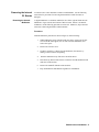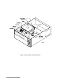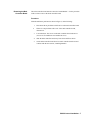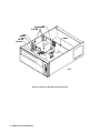
1
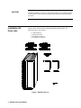
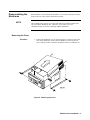
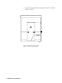
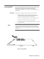
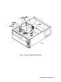
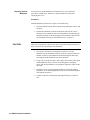
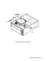
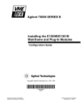
75000 SERIES B
Instrument BASIC
Installation Note
Copyright © Agilent Technologies, Inc., 1990 - 2006
*E1300-90020*
E1300-90020
E0606
Manual Part Number: E1300-90020
Microfiche Part Number: E1300-99020
Printed: June 2006
Printed in Malyasia
Edition 1 Rev 2
E 0606
Agilent Instrument BASIC Installation Note
Introduction
This installation note contains procedures for installing Instrument BASIC
(IBASIC) in the Agilent 75000 Series B Mainframe using the E1300-80001
Installation Kit.
This installation note is divided into the following sections:
•
•
•
•
•
•
NOTE
Warnings and Cautions
Installation Kit Parts List
Disassembling the Mainframe
Installing IBASIC
Reassembling the Mainframe
What to do Next
This installation note applies to Agilent 75000 Series B Mainframes with serial
prefix (first four digits of the serial number) 3034 and above for the E1300A and
3035 and above for the E1301A. If you have an earlier serial prefix, contact you
local field support office for instructions.
The IBASIC installation also requires at least 512 Kbyte of memory.
1
Warnings and
Cautions
WARNING
Take note of the following warnings and cautions while using this installation note.
Remove the power cord and all other sources of power supplied (via other plug-in
modules) to the mainframe.
Only qualified, service-trained personnel should install IBASIC inside the Agilent
75000 Series B Mainframe.
IBASIC Internal Installation - 1
CAUTION
The IBASIC ROMs are sensitive to electrostatic discharge. This installation should
be performed at a static-controlled workstation that includes personnel grounding
provisions.
1
Installation Kit
Parts Lists
Figure 1 shows the items in the E1300-80001 IBASIC Installation Kit. The
following tools are also required:
•
•
•
•
6 mm Nut Driver
Needle-Nose Pliers
Flat-Blade Screwdriver
#2 Pozidrive Screwdriver
Figure 1. IBASIC Parts List
2 - IBASIC Internal Installation
1
Disassembling the
Mainframe
Before IBASIC can be installed, the mainframe cover and some internal PC boards
must be removed. This section contains the procedure.
NOTE
This installation note requires you to disconnect the main controller which causes
any stored data in RAM to be lost. Therefore, if you want to save your
configuration files, do it before continuing with this installation.
Removing the Cover
Procedure
1.
Remove the mainframe cover by removing the two T10 torx screws at the
back of the mainframe. Remove the side handles by removing the four
screws with a pozidrive screwdriver. Pull back on the cover and lift it off.
Figure 2. Removing the Cover
IBASIC Internal Installation - 3
2.
Remove the top support bracket by removing the T10 torx screw and then
lifting the bracket off.
Figure 3. Removing the Bracket
4 - IBASIC Internal Installation
Removing the Internal
PC Boards
Removing the Internal
Multimeter
You must remove some internal PC boards to install IBASIC. See the following
subsections for procedures for removing the Internal PC boards from slots 0
through 3.
A digital multimeter is sometimes installed in slot 2 of the Agilent 75000 Series B
Mainframe. Figure 4 shows the location of this PC board. If there is an internal
multimeter, use the following procedure to removed it. Otherwise, skip to the next
subsection, "Removing the Main Controller Board."
Procedure
With the mainframe positioned as shown in figure 4, do the following:
1.
While holding the spacer with the needle-nose pliers, remove the T8 torx
screw from the front support (one on each side of the multimeter) and
remove the spacer.
2.
Remove the T10 torx screw.
3.
If a BNC connector is connected to the multimeter, disconnect it by
turning counter clockwise and pulling.
4.
Slide the multimeter away from slot 2 and lift as shown.
5.
Disconnect any ribbon cable and wire connectors from the multimeter and
make note of the location.
6.
Remove the standoffs with the 6 mm nut driver.
7.
Keep the multimeter and hardware together for reinstallation.
IBASIC Internal Installation - 5
Figure 4. Removing the Internal Multimeter
6 - IBASIC Internal Installation
Removing the Main
Controller Board
The main controller board must be removed to install IBASIC. Use the procedure
in this section to remove the main controller board.
Procedure
With the mainframe positioned as shown in figure 5, do the following:
1.
2.
Disconnect the 50 pin ribbon cable from J2 on the main controller board.
If there is a 40 pin ribbon cable on J1 of the main controller board,
disconnect it.
3.
Loosen the three T10 screws on the main controller board and remove
(two screws if a multimeter was installed in slot 2).
4.
Slide the main controller board away from slot 0 and lift as shown.
5.
Set the main controller board down in a static-controlled work area and
continue with the next section, "Installing IBASIC."
IBASIC Internal Installation - 7
Figure 5. Removing the Main Controller Board
8 - IBASIC Internal Installation
1
Installing IBASIC
Procedure
NOTE
The PC boards in slots 0 through 3 (internal slots) must be removed before IBASIC
can be installed. This should have been done in the "Disassembling the
Mainframe" section. If these PC boards are not removed, return to the
"Disassembling the Mainframe" section. Otherwise, continue with this section to
install IBASIC.
With the main controller board positioned as in figure 6, do the following:
1.
Remove the ROMs in U21, U22, U33, and U34 by sliding a small
flat-blade screwdriver under the ROM and slowly prying the device up
from one end. Pull the device up one pair of pins at a time.
2.
Insert the new programmable ROMs into the corresponding grip sockets.
3.
Place the new PC board label over the PC board part number.
4.
Continue with the next section, "Reassembling the Mainframe," to reinstall
the internal PC boards.
If you are installing a 3 1/2" Floppy Disk Drive (Installation Kit E1300-80005), a
20 Mbyte Hard Disk (Installation Kit E1300-80006), or a Disk Controller Board
(Installation Kit E1300-80011), you should install these items before reassembling
the mainframe.
Figure 6. Installing IBASIC
IBASIC Internal Installation - 9
1
Reassembling the
Mainframe
Once IBASIC is installed, use the following procedure to reassemble the
mainframe. This section is divided into two subsections:
Replacing the Internal PC Boards
Replacing the Cover
Replacing the Internal
PC Boards
Replacing Main
Controller Board
Some internal PC boards were removed for the IBASIC installation procedure.
This section provides a procedure for reinstalling these PC boards.
Use the following procedure to reinstall the main controller board in slot 0 of the
Agilent 75000 Series B Mainframe.
Procedure
With the mainframe positioned as shown in figure 7, do the following:
10 - IBASIC Internal Installation
1.
Turn the main controller board over and line the pins up with the slot 0
backplane connector. Lower the main controller board into the mainframe
and insert it into the connector. Make sure the board rests on the three
support brackets.
2.
Line the board up with the holes and insert the three T10 torx screws and
tighten (omit one screw if the internal multimeter will be reinstalled).
3.
Connect the 40 pin ribbon cable to J1 of the main controller board.
4.
Connect the 50 pin ribbon cable to J2 of the main controller board.
Figure 7. Replacing the Main Controller Board
IBASIC Internal Installation - 11
Replacing Internal
Multimeter
If you removed a digital multimeter from internal slot 2, use the following
procedure to reinstall the it. Otherwise, continue with the next subsection,
"Replacing the Cover."
Procedure
With the mainframe positioned as in figure 8, do the following:
CAUTION
12 - IBASIC Internal Installation
1.
Insert the standoffs into the main controller board and tighten with a 6 mm
nut driver.
2.
Position the multimeter (component side down) and route the colored
analog bus wires and ribbon cable from the multimeter faceplate through
the plastic grommets on the front support. Insert the black connectors into
the same plastic housing you removed them from. See figure 8.
Make sure you plug these connectors into the correct plastic housing. Reversal of
these connectors can cause damage to the instrument.
3.
Line the pins up with the slot 2 backplane connector. Lower the
multimeter into the mainframe and insert it into the connector. Make sure
the BNC connector on the multimeter protrudes through the hole in the
front support and the multimeter rests on the standoff.
4.
Using a pair of needle-nose pliers, hold a spacer between the front support
and the multimeter. Insert a T8 torx screw through the front support,
spacer, and into the multimeter. Do not tighten completely. Repeat for the
other side.
5.
Insert the T10 torx screw through the multimeter and into the standoff.
Tighten the screw and then tighten the T8 torx screws inserted through the
front support and spacers.
6.
If a BNC connector was disconnected during disassembly, reconnect it
now.
Figure 8. Replacing the Internal Multimeter
IBASIC Internal Installation - 13
Replacing the Cover
Procedure
Now that all the internal PC boards have been reinstalled, use the following
procedure to replace the cover.
1.
Reinstall the top support bracket removed in the "Disassembling the
Mainframe" section with the T10 torx screw.
2.
Place the cover on the mainframe and slide it towards the front of the
instrument until the holes on the sides of the cover line up with the holes
on the mainframe chassis.
3.
Attach the handles.
4.
Replace the two T10 torx screws at the back of the instrument.
5.
Cover any unused slots to preserve the intended airflow pattern of the
cooling fan.
1
What to do Next
14 - IBASIC Internal Installation
Once you have the Agilent 75000 Series B mainframe reassembled, see the "Using
Instrument BASIC With the Agilent E1300B/E1301B" Manual for information on
the IBASIC mode of operation, disk configuration, and writing IBASIC programs.