1
[RDFTX
MODEL N
917.258671
®
OWNER'S
MANUAL
®Assembly
®Operation
• Customer Responsibilities
o Service and Adjustments
®Repair Parts
CAUTION:
Read and follow all safety rules and instructions
FOR CONSUMER
iiiiii
!
ASSISTANCE
before operating
HOT LINE, CALL THIS TOLL FREE NUMBER:
! i! i!ili!ii!i
!illli
iiiiiii
!H!ii!
!i]!ilili
lllllllllllllllllllllllllllllllllllllllll
this equipment.
1-800-659-5917
i.--
SAFETY
Safe Operation
Practices RULES
for Ride-On Mowers
IMPORTANT:
THIS CUTTING
FAILURE
TO OBSERVE
THE
I.
•
•
,,
•
.
°
•
,,
•
•
•
•
•
,,
o
II.
MACHINE
FOLLOWING
IS CAPABLE
OF AMPUTATING
HANDS AND
SAFETY
INSTRUCTIONS
COULD
RESULT
GENERAL OPERATION
Read, understand, and follow all instructionsin the manual
and on the machine before starting.
Only allow responsible adults, who are familiar with the
instructions, to operate the machine
Clear the area of objects such as rocks, toys, wire, etc,
which could be picked up and thrown by the blade,
Be sure the area isclear of other people before mowing Stop
machine if anyone enters the area
Never carry passengers
Do not mow in reverse unless absolutely necessary. Always
look down and behind before and while backing
Be aware of the mower discharge direction and do not point
it at anyone Do not operate the mower without either the
entire grass catcher or the guard in place
Slow down before turning
Never leave a running machine unattended Always turn oil
blades, set parking brake, stop engine, and remove keys
before dismounting
Turn off blades when not mowing
Stop engine before removing grass catcher or unclogging
chute
Mow only in daylight or good artificial light
Do not operate the machine while under the influence of
alcohol or drugs
Watch lot traffic when operating near or crossing roadways
Use extra care when loading or unloading the machine into
a trailer or truck
SLOPE
slope
or if you feet
uneasy
on it, do not mow
CHILDREN
•
Never carry chiEdren. They may fall off and be seriously
injured or interfere with safe machine operation
Never allow children to operate the machine,
Use extra care when approaching blind corners, shrubs ._
trees, or other objects that may obscure vision.
,,
•
IV. SERVICE
•
Use extra care in handling gasoline and other fuels
fFammable and vapors are explosive
Use only an approved
They are
container.
Never remove gas cap or add fue! with the engine
running.
Allow engine to cool before refueling
Do not
smoke
Never refuet the machine
indoors
Never slore the machine or' fuel container inside where
there is an open flame, such as a water heater
Never run a machine inside a closed area.
•
,,
Keep nuts and bolts, especially blade attachment
and keep equipment in good condition
•
Never tamper with
operation regularly
°
Keep machine free of grass, leaves, o_ other debris build-up
Clean oil or fuel spillage
Allow machine
to cool be!ore
storing
°
Stop and inspect the equipment
if you strike an obiect
Repair, it necessary, before restarting
Never make adjustments
or repairs with the engine funning
it.
DO:
OBJECTS.
OR DEATH
Tragic accidents can occur if the operator is not alert to the
presence of children,
Children are often attracted to the
machine and the mowing activity
Never assume that
children wilt remain where you last saw them..
•
Keep children out of the mowing area and under the walchful
care of another responsible adult
"
Be alert and turn machine off if children enter the area
•
Before and when backing, look beh!,_d End down for sm&ll
children
OPERATION
S_opes are a major factor related to loss-of-control and
tipover accidents, which can resutt in severe injury or
death, All slopes require extra caution. If you cannot back
up the
III.
FEET AND THROWING
IN SERIOUS
iNJURY
safely
devices.
Check
bo_ls fight
their
proper
•
,,
Mow up and down slopes, not across
Remove obstacles such as rocks, tree limbs, etc
•
Watch for holes, ruts, or bumps.
Uneven
terrain
overturn the machine.
Taft grass can hide obstacles
could
•
•
Use slow speed Choose a low gear so that you wilt not have
to stop or' shift while on the slope
Follow the manufacturer's
recommendations
for wheel
weights or counterweights
to improve stability
Use extra care with grass catchers or other attachments
These can change the stability of the machine
Grass catcher components
are subiect to wear, damage, and
deterioration,
which could expose moving parts or altow
objects to be thrown.
Frequently
check components
and
replace with manufacturer's
recommended
parts when necessary
•
Mower blades are sharp and can cu_ Wrap the blade(st or
wear gloves, and use extra caution when servicing Ihem
Check brake operation
frequently
Adjust and service as
required.
•
.
•
°
Keep all movement on the slopes slow and gradual
make sudden changes in speed or direction
•
Avoid starting or stopping on a s!ope. If tires fose traction,
disengage
the blades and proceed slowly straight down the
stope
,
Do not
DO NOT:
Look for this symbol to point out important
safety
precautions°
It
means
CAUTtON!!t
BECOME
ALERT!!!
YOUR
SAFETY IS INVOLVED.
..............
•
Donottumonslopesunlessnecessary,andthenturnslowiy
and gradually downhill, if possible
•
Do not mow near drop-offs, ditches, or embankments
The
mower could suddenly turn over if a wheel is over the edge
of a cliff or ditch, or if an edge caves in
•
Do not mow on wet grass.
sliding
°
Do not try to stabilize
ground
•
Do not use grass catcher
Reduced
the machine
on sleep
traction
could
I II _
:
==!
i Jj
I,I ,
cause
by putting your foot on the
stopes
ILLUIU,IUIUI
I /Ul Jl,I
CAUTION:
Always disconnect
spark plug
wire and place wire where it can not co nt act
accidental
in order
spark plug
to prevent
starting
when setting
up, transporting
adjusting
or making repairs,
A WARNING
The engine exhaust from this product contains
chemicals
known to the State of California to
cause cancer, birth defects, or other' reproductive harm.
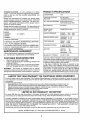
PRODUCT
CONGRATULATIONS
on yourpurchaseof a Sears
Tractor,Ithasbeendesigned,
engineered and manufactured to give you the best possible dependability and
performance°
Should you experience any problem you cannot easily
remedy, please contact your nearest Sears Authorized
Service Center/Department Department° We have competent, well-trained technicians and the proper tools to
service or repair this tractor.
Please read and retain this manual° The instructions will
enable you to assemble and maintain your tractor proper]y_
Always observe the "SAFETY RULES"°
MODEL
NUMBER
SERIAL
NUMBER
917.258671
SPECIFICATIONS
HORSEPOWER:
19,5
GASOLINE CAPACITY
AND TYPE:
3,5 GALLONS
UNLEADED REGULAR
OIL TYPE (APt-SF/SGtSH);
SAE 30 (above 32°F)
SAE 5W-30 (below 32°F)
OIL CAPACITY:
3.,0 PINTS
SPARK PLUG:
(GAP: ,030")
CHAMPION RJ19LM
VALVE CLEARANCE:
INTAKE:
,004"EXHAUST: 007"-
GROUND SPEED (MPH):
FORWARD:
REVERSE;
TIRE PRESSURE:
FRONT:
REAR:
CHARGING SYSTEM:
3 AMPS BATTERY
5 AMPS HEADLIGHTS
BATTERY:
AMPtHR:
MtN. CCA:
CASE SIZE:
BLADE BOLTTORQUE:
30-35 FT. LBS
DATE OF PURCHASE
THE MODEL AND SERIAL NUMBERSWILL
BE FOUND
ON A PLATE UNDER THE SEAT,
YOU SHOULD RECORD BOTH SERIAL NUMBER AND
DATE OF PURCHASE AND KEEP IN A SAFE PLACE
FOR FUTURE REFERENCE.
MAINTENANCE
AGREEMENT
A Sears Maintenance Agreement is available on this product,. Contact your nearest Sears store for details°
CUSTOMER
•
o
°
This tractor is equipped with an internal
engine and should not be used on or near any
forest-covered,
brush*covered
or grass-cov-
LIMITED TWO YEAR WARRANTY
0- 5,.5
0-24
14 PSI
10 PSI
30
240
UIR
ered land unless the engine's exhaust system is equipped
with a spark arrester meeting applicable local or state laws
(if any)._If a spark arrester is used, it should be maintained
in effective working order by the operator,
In the state of California the above is required by law
(Section 4442 of the California Public Resources Code)._
Other states may have similar laws. Feder_=ilaws apply on
federal lands. A spark arrester for the muffler is available
through your nearest Sears Authorized Service Center/
Department (See REPAIR PARTS section ofthis manual)..
RESPONSIBILITIES
Read and observe the safety rules°
Follow a regular schedule in maintaining, caring for and
using your tractor..
Follow the instructions under"Customer
Responsibilities" and "Storage" sections of this owner's manual°
WARNING:
combustion
unimproved
,006"
.009"
ON CRAFTSMAN
RIDING EQUIPMENT
For two (2) years from the date of purchase, if this Craftsman Riding Equipment is maintained, lubricated and tuned up according
to the instructionsin the owner's manual, Sears will repair or replace, free of charge, any parts found to be defective in material or
workmanship,
This Warranty does not cover:
•
Expendable items which become worn dudng normal use, such as blades, spark plugs, air cleaners, belts, etc.
•
Tire replacement or repair caused by punctures from outside objects, such as nails, thorns, stumps, or glass.
•
Repairs necessary because of operator abuse, negligence, improper storage or accident or the failure to maintain the
equipment according to the instructions contained in the owner's manual
•
Riding equipment used for commercial or rental purposes_
LIMITED
90 DAY WARRANTY
ON BATTERY
I,
For ninety (90) days from date of purchase, if any batten] included with this riding equipment proves detective in material or
workmanship and our testing determines the battery will not hold a charge. Sears will replace the battery at no charge,
IN-HOME WARRANTY SERVICE ON YOUR CRAFTSMAN RIDING EQUIPMENT tS AVAILABLE AT NO-CHARGE FOR 30
DAYS FROM THE DATE OF PURCHASE. PLEASE CONTACT YOUR NEAREST SERVICE CENTER, AFTER 30 DAYS FROM
THE DATE OF PURCHASE, WARRANTY SERVICE IS AVAILABLE BY TAKING YOUR CRAFTSMAN RIDING EQUIPMENT TO
YOUR NEAREST SEARS SERVICE CENTER. (IN-HOME WARRANTY SERVICE WILL STILL BE AVAILABLE AFTER 30 DAYS
FROM THE DATE OF PURCHASE BUT A STANDARD TRIP CHARGE WILL APPLY) THIS WARRANTY APPLIES ONLY
WHILE THIS PRODUCT 1SIN THE UNITED STATES.
This Warranty gives you specific legal rights, and you may also have other rights which may vary from state to state
SEARS,
ROEBUCK
AND CO,, D/817 WA, HOFFMAN
3
ESTATES,
IL 60'179
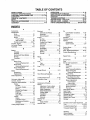
TABLE OF CONTENTS
OPERATION ........................................................... 11-16
MAINTENANCE SCHEDULE ...................................... 17
SERVICE AND ADJUSTMENTS ............................ 21-27
STORAGE ...................................................................
28
TROUBLESHOOTING ............................................ 29-30
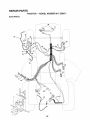
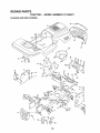
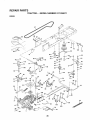
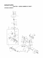
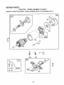
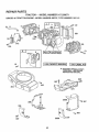
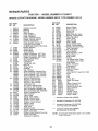
REPAIR PARTS - TRACTOR ................................. 32-47
REPAIR PARTS - ENGINE .................................... 48-53
PARTS ORDERING/SERVICE .................. BACK PAGE
SAFETY RULES ............................................................ 2
PRODUCT SPECIFICATIONS ...................................... 3
CUSTOMER RESPONSIBILITIES ..................... 3, 17-20
WARRANTY .................................................................. 3
TABLE OF CONTENTS ................................................ 4
INDEX ...................................................................... ...... 4
TRACTOR ACCESSORIES .......................................... 5
ASSEMBLY .............................................................. 7-10
INDEX
A
E
O
Accessories ............................................................
5
Electrical:
Oil:
Adjustments:
Cold Weather Conditions .........14,19
Interlocks and Relays ........................
26
Brake ..............................................................
24
Schematic................................................
31
Engine ..........................................................
19
Carburetor ..................................................
27
Wiring Diagram ...................................
32
Storage .............................
28
Mower:
Engine:
Operation ..............................................
11-16
Front-To-Back ...........................22
Air Filter
.........................................
19
Operating Mower ..........................
14
Side-To-Side ............................ 22
Air Screen ........................................19
Options:
Throttle Control Cable ..............26-27
Accessories ..............................................
5
Cooling Fins, Engine ..........................
20
Air Filter, Engine ..................................................
19
Spark Arrester. ........................
3,40
Oil Change ...................................................
19
Air Screen, Engine ............................................
19
Oil Level ..........................................
14,19
P
Assembly ...................................................
7-t0
OilType ..............................................
19
Parking Brake .......................................
12-13
B
Preparation ......................................14
Parts Bag ...............................................................
6
Repair Parts ..........................................
48-53
Battery:
Parts, Replacement/Repair. ..................
32-47
Starting ....................................................
14
Charging ................................................
18
Product Specifications .................................
3
Storage ..............................................................
28
Cleaning .....................................................
18
R
F
Starting with Weak Battery ...............
26
Repair Parts ..............................................
32-47
Filters:
Storage .....................................................
28
S
Terminals .............................................
18
Air ................................................................
19
Belts:
Fuel .................................................................
20
Safety Rules .......................................................
2
Seat .............................................................................
8
Motion Drive
Fuel:
Service
and
Adjustments
.................
2
1-27
Removal/Replacement .............24
Type ............................................................
14
Mower Drive
Brake .............................................................
24
Storage ..............................................
28
Carburetor ............................................
27
RemovallReptacement .............23
Fuse ..........................................................................
26
Mower Blade Drive
Fuse .......................................................
26
G
Hood Removal/Installation ........... 26
Removal/Replacement ..................
23
Gauge Wheets ........................................
9,14
Motion Drive Belt
Blade:
H
RemovaL/Replacement .............24
Sharpening .............................................
18
Hood RemovaIllnstatlation ........................
26
Mower Drive
Replacement .......................................
18
Removal/Replacement .............23
Brake Adjustment ......................................
24
L.
Mower' Blade Drive Belt
C
Leveling Mower Deck ..........................
21-22
Removal/Replacement ..............23
LubricationChart ...............................................
17
Carburetor Adjustment .............................
27
MowerAdjustment:
Controls, Tractor .............................................
13
M
Front-to-Back .................................
22
Customer Responsibilities ...........3,17-20
Maintenance Schedule ................................
17
Side4o-Side.......................
22
Engine:
Mower:
Mower Installation ...........................21
Air Filter ..................................................
19
Adjustment, Front-to-Back .............22
Mower Removal ......................................
21
Air Screen, Engine .........................
19
Adjustment, Side4o-Side ...................
22
Tire Care ............................
6,18,25
Battery ...................................................
18
Blade Sharpening ...............................
18
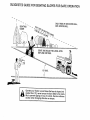
Slope Guide Sheet .................................55
Cooling Fins, Engine ...................19
Blade Replacement ....................... 18
Spark Plugs ......................................................
20
Engine Oil ..........................................
20
Cutting Height .................................
13
Specifications ......................................................
3
FuelFilter'.
.............................................
20
Installation ...................................................
9,21
Starting the Engine ........................................
t4-15
Spark Plugs......................................
18
Operation ..................................................
11-16
Steering Wheel .....................................................
7,25
Tractor:
Removal ..........................................................
21
Stopping the Tractor .......................
13
Blades ..............................................
18
Mowing Tips ............................................................
16
Storage
.................................
28
Lubrication Chart .................................
17
Muffler. .........................................
_'...............
20
Maintenance Schedule ............ 17
T
Spark AtTester .........._....................3,40
Tire Care ............................
8,18,25
Throttle
Control
Cable
Adjustment ........26
MulcherPlate......................................................
10
Tires ........................................................
8,18,25
Cutting Height, Mower ................................
13
Trouble Shooting Chart .................. 29-30
Transaxle Repair Parts ........................
46-47
W
4
Warranty .............................................................
3
Wiring Diagram ...................................................
32
Wiring Schematic ................................................
31
ACCESSORIES
AND ATTACHMENTS
.......................................
_.......................
ii1,,,,i,1,,i, iii
iiii
ii
IHHm'II
III
I
These accessories and attachments were available throughmost Sears retail outlets and service centers when the tractor was purchased
Most Sears stores can order these items for you when you provide the model number of your tractor
ENGINE
SPARK PLUG
MAINTENANCE
GAS CAN
ENGINE OIL
FUEL STABILIZER
AIR FILTER
BLADES
BELTS
%
PERFORMANCE
Sears offers a wide variety of attachments that fit your tractor.. Many of these are listedbelow with brief explanations of how they can help
you. This list was current at the time of publication;however, it may change in future years - more attachments may be added, changes
may be made in these attachments, or some may no longer be available orfit your model Contact your nearest Sears store for the
accessories and attachments that are available for your tractor.
Most of these attachments do not require additional hitches or conversion kits (those that do are indicated) and are designed for easy
attaching and detaching.
AERATOR promotes deep root growth for a healthy lawn.. Tapered 25-inch steel spikes mounted on 10+inch diameter discs
puncture holes in soil at close intervals to let moisture soak in.
Steel weight tray for increased penetration.
BAGGER lets you collect grass clippings and leaves for a
heatthier, heater looking lawn° Two Permanex containers hold
30.gallon plastic bags.
BUMPER protects front end of tractor from damage+
CARTS make hauling easy_ Variety of sizes available, plus
accessories such as side panel kits, toot caddy, cart cover,
protective mat and doily.
CORING AERATOR takes small plugs out of soil to allow moisture and nutrients to reach grass roots 36+inch swath
24
hardened steel coring tips 150 Ib.. capacity weight tray..
EASY OIL DRAIN VALVE makes oil changes easier, faster
FRONT NOSE ROLLER canters in front of mower deck to reduce
chances of "scarping" on uneven terrain.
GANG HITCH lets you tow 2 or 3 pu_Fbehindattachments at once,
such as sweepers, dethatchers, aerators (not for use with rollers,
carts or other heavy attachments)..
GAUGE WHEELS on both sides of the mower deck reduce
chances of "scalping" on uneven terrain.. For mower decks not so
equipped.
MULCH RAKF.JDETHATOHER loosens soil and flips thatch and
matted leaves to lawn surface for easy pickup. Twenty spring tine
teeth° Useful to prepare bare areas forseedfng. Available for front
or rear mounting.
HIGH PERFORMANCE REEL-ACTION
SPRING TINE DETHATCHER covers 36+inch wide path and
tosses thatch into large hopper Mounts behind tractor
MULCHING CLOSE-OUT PLATE KIT, once installed, lets you
muich, discharge or bag clippings (bagger optional) without
changing blades_ For models not equipped as 3-in-1 Convertible
mowers. See "MOWER" in the Repair Parts section of this
manual..
RAMP TOPS AND FEET let you load and unload tractor from a
pickup truck Use with 2 x 8 or 2 x 10 lumber
ROLLER for smoother lawn surface. 36-inch wide, 18+inch
diameterwater-tightdrum holds up to 390 Ibs of weight. Rounded
edges prevent harm to turf Adjustable scraper automatically
cleans drum..
SNOW BLADE for snow removar only. 14-inch high, 48-inch wide
blade clears 42-inch pathwhen angted leftor right. Raises, lowers
with side lever. Adjustable skids; replaceable, reversible scraper
bar,. (Use with tire chains and wheel weights and/or rear drawbar
weight.)
SNOWTHROWER has 40+inch swath.. Drum-type auger handles
powdery and wet/heavy snow. Mounts easily with simple pin
arrangement Discharge chute adjusts from tractor seat 6-inch
diameter spout discharges snow t0 to 50 feet. Lift controlled at
tractor seat, (Use with chains and wheel weights and/or rear
drawbar weight..)
SPRAYERS use 12-volt DC electric motor that connects to the
tractor battery or other 12-volt source
includes booms for
automatic spraying and hand held wand for spot spraying, Wand
has adjustable spray pattern, For applying herbicides, insecticides, fungicides and liquid fertilizers.
SPREADER/SEEDERS make seeding, fertilizing, and weed killing easy. Broadcast spreaders are also useful for granular deicers and sand.
SWEEPERS let you cotiect grass clippings and leaves
TILLER has 5 hp engine and 36+inch swath to prepare seed beds,
cultivate and compost garden residue_ Tiller has its own built-in
liftand depth control system and does NOT require a sleeve hitch°
Fits anylawn, yardorgardentractor.. Simply hook up to the tractor
drawbar and go! Optional accessories
convert unit for
dethatching, aerating, hilling,....without tools,
TIRE CHAINS are heavy duty; closely spaced extra-large cross
links give smooth ride, outstanding traction.
TRACTOR CAB has heavy duty vinyl fabric over tubular steel
frame, ABS plastictop; clear plastic windshield offers 360 degree
visibility+ Hinged metal doors with catch. Keeps operator warm
and dry.. Remove vinyi sides and windshields for use as sun
protector in summer. Optional accessories include: tinted/
tempered solid safety glass windshield with hand operated wiper;
12-volt amber caution tightfor mounting on cab top.
VACS for powerful collection of heavy grass clippings and leaveso
Optional wand attachment to pick up debris in hard-to+reach
places. VAC/CHIPPER incfudes a chipper-shredder°
WEIGHT BRACKET for drawbar for snow removal applications.
Uses (t) 55 Ib. weight.
WHEEL, WEIGHTS for rear wheels provide needed traction for
snow removal or dozing heavy materials.
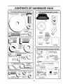
CONTENTS
OF HARDWARE
PACK
ii
Parts Bag contents
shown full size
ii
IHIII, IIIII III
Parts packed separately
i lll
lul i
i, i i i i
INNNNIIINI
in carton
I IINNmUHIIN
I
Seat
Video
Cassette
Steering
Wheel
5/16-18_
(l)HexBolt
_))
--_
_ _]_f]_t_,5/16-18
Mufcher
Plate
× 1-1/4
Iir
,
Jnl_/lll
Hill
i
(1) HexBo!! I12-13 x I
IIFiHili
il.
Steering
Boot
Manual
,i
Parts Bag
it,,Jl/,,,,,,,,,,,,,,,,,,
,, ,,, ,, ,,,,
Parts bag contents
,,,
,,,,,,,,
,
not shown full size
(2) Washers 3/8
x 7/8 x 14 Gauge
/
(2) Screws #10 x 5/8
Washers #10 % i
.r--J
(2) Weld i
i
(2) Washers I
3116 x 314 _
x 16 Gauge
(2) Shoulder
Bolts
L-I!
(2) CenteP
)
/
lock Nuts
(_)
Wheels _
(2) Gauge r4:;;FR_
Steering Wheel
Adapter'
Nuts #10 _
_nt
Link Assemblies
(2) Latch Hook
Assemblys
_ts
114-20 X 3/4 _(2)
Steering
Wheel
Insert
HeX Nuts
13!llIfH_IIIl!II!Itlt!!_/--_
i c_ J>,/4._o
i
.
_1_
(2) Wasners _
9/32 x 5/8 x t6 Gauge
(2) Keys
./
(2) Lock
l
Washers 1/4
.......................
Steering
Extension
Shaft
O
Slope Sheet
i
6
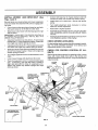
BLY
Your new tractor has been assembled at the factory with exception of those parts left unassembled for shipping purposes.
To ensure safe and proper operation of your tractor all parts and hardware you assemble must be tightened secure_y.. Use
the correct tools as necessary to insure proper tightness.
TOOLS REQUIRED
FOR ASSEMBLY
A socket wrench set will make assembly easier_ Standard
wrench sizes are listed°
(1)
(2)
(2)
(1)
9/16" wrench
7/16" wrenches
1/2" wrench
3/4" wrench
(1) 3/4" Socket w/drive rachet
Phillips Screwdriver
Tire pressure gauge
Utility knife
Pliers
LARGE FLAT
WASHER
When right or left hand is mentioned in this manual, it
means when you are in the operating position (seated
behind the steering wheel)r
STEERING
WHEEL
STEERING
TO REMOVE TRACTOR FROM CARTON
UNPACK
,
,
°
-
BOOT
CARTON
EXTENSION
Remove ai! accessible loose parts and parts cartons
from carton (See page 6)..
Cut, from top to bottom, along lines on all four corners
of carton, and lay panels flat.
Remove mower and package materials.
Check for any additional loose parts or cartons and
remove.
5/16 HEX
BOLT
/
BEFORE ROLLING TRACTOR OFF SKID
ATTACH STEERING
APTER
•
t
LOWER
STEERING
SHAFT
WHEEL (See Fig. 1)
., ",
,I
•
# t1
tt
ASSEMBLE EXTENSION SHAFT AND BOOT
=
Slide extension shaft onto lower steering shafL Align
mounting holes in extension and lower shafts and
install 5/t6 hex bolt and locknut. Tighten securely.
IMPORTANT: TIGHTEN BOLT AND NUT SECURELY TO
18-22 FT, LBS TORQUE.
FIG. 1
•
TO ROLL TRACTOR OFF SKID (See Operation section for location and function of controls)
Place tabs of steering boot over tab slots in dash and
push down to secure°
=
iNSTALL STEERING WHEEL
°
Position front wheels of the tractor so they are pointing
straight forward.
•
=
Slide steering wheel adapter onto steering shaft extension.
°
=
Position steering wheel so cross bars are horizontal
(left to right) and slide inside boot and onto adapter.
•
Assemble large fiat washer, 3/8 lock washer, 3/8 hex
bolt and tighten securely.
•
Snap steering wheel insert into center of steering
wheel°
°
•
•
Remove protective materials from tractor hood and
gritlo
• IMPORTANT: CHECK FOR AND REMOVE ANY STAPLES
IN SKlD THAT MAY PUNCTURE TIRES WHERE TRACTOR
iS TO ROLL OFF SKID..
7
Press lift lever plunger and raise attachment liftlever to
its highest position,
Release parking brake by depressing chJtch/brake
pedal
Place freewheel control in freewheeling position to
disengage transmission (See "TO TRANSPORT" in
the Operation section of this manual)°
Roll tractor backwards off skid..
Remove banding holding discharge guard up against
tractor°
ASSEMBLY
HOW TO SET UP YOUR TRACTOR
CONNECT
BATTERY
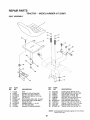
INSTALL SEAT (See Fig. 3)
Adjust seat before tightening adjustment bolt.
•
Remove cardboard packing on seat pan=
•
Place seat on seat pan and assemble shoulder bolt.
•
Assemble adjustment bolt, lock washer and flat washer
loosely. Do not tighten.
° Tighten shoulder bolt securely,,
•
Lower seat into operating position and sit on seat°
•
Slide seat until a comfortable position is reached which
allows you to press clutchforake pedal all the way
down,
(See Fig. 2)
nals by allowing a wrench or any other
CAUTION:
Do notboth
short
battery termiobject
to contact
terminals
at the
sametime. Before connecting battery,
remove metal bracelets, wristwatch
bands, rings, etc.
Positive terminal must be connected
first to prevent sparking from accidental grounding.
°
°
•
•
Lift hood to raised position,
Open terminal access doors, remove terminal protective caps and discard.
•
If this battery is put into service after month and year
indicated on label (label tocated between terminals)
charge battery for minimum of one hour at 6-t0 amps,
•
First connect RED battery cable to positive (+) battery
terminal with hex bolt, flat washer', lock washer and hex
nut as shown,, Tighten securely.
•
Connect BLACK grounding cable to negative (-) battery terminal with remaining hex bolt, flat washer, lock
washer and hex nut. Tighten securely.
•
Close terminal access doors.
Use terminal access doors for:
•
•
•
•
•
SEAT ,=AN
DISCARD TERMINAL
PROTECTIVE CAPS
LOCK
WASHER
,__ -_"__,_,-"_
[_ (
•
FIG. 3
Inspection for secure connections (to tighten hardware),,
Inspection for corrosion.
Testing battery,,
Jumping (if required),,
Periodic charging°
HEX NUT
Get off seat without moving its adjusted position,
Raise seat and tighten adjustment bolt securely,
CHECK
TIRE
PRESSURE
The tires on your tractorwere overinflated at the factory for
shipping purposes,, Correct tire pressure is important for
best cutting performance.
°
Reduce tire pressure to PSI shown in "PRODUCT
SPECIFICATIONS" on page 3 of this manual.
FLAT
WASHER
CHECK BRAKE SYSTEM
\\
After you learn how to operate your tractor, check to see
that the brake is properly adjusted. See 'q'O ADJUST
BRAKE" in the Service and Adjustments section of this
manual
ACCESS
DOOR
CABLE
NEGA_VE
(BLAC_
CABLE
FIG. 2
8
ASSEMBLY
INSTALL MOWER
Figs. 4 and 7)
AND DRIVE BELT
°
(See
°
Be sure tractor is on level surface and mower suspension
arms are raised with attachment lift control, Engage parking brake,
*
Cut and remove ties securing anti-sway bar and belts,
Swing anti-sway bar to left side of mower deck,
,
Slide mower under tractor with discharge guard to right
side of tractor.,
IMPORTANT: CHECK BELT FOR PROPER ROUTING IN
ALL MOWER
PULLEY
GROOVES,
INSTALL BELT INTO
ENGINE
PULLEY
install one front link in top hole of the LH. front mower
bracket and LH, front suspension bracket,, Retain with
two single loop retainer springs as shown.
°
Install second front link in R_H,front suspension bracket
and retain with single loop retainer spring as shown..
-
Slide right side of mower back and install link in top hole
of R,H, front mower bracket, Retain with single loop
retainer spring as shown.
Turn height adjustment knob counterclockwise until it
stops,,
Lower mower linkage with attachment lift control,
•
•
•
Turn height adjustment knob clockwise to remove
slack from mower suspension_
•
Raise deck to highest position,
.
Assemble gauge wheels as shown using long shoulder
bolts, 3/8 washers, and 3/8-16 center Iocknuts. Tighten
securely.
•
Adjust gauge wheels before operating mower as shown
in the Operation section of this manual.
GROOVE,,
•
°
Connect antFsway bar to chassis bracket under left
footrest and retain with double loop retainer spring,,
Install clutch rod in clutch lever., Secure with retainer
spring,
CHECK MOWER
LEVELNESS
For best cutting resuits, mower should be properly leveled.
See "TO LEVEL MOWER HOUSING" in the Service and
Adjustments section of this manual°
CHECK
BELTS
FOR PROPER
POSITION
OF ALL
See the figures that are shown for replacing motion, mower
drive, and mower blade drive belts in the Service and
Adjustments section of this manual. Verify that the belts are
routed correctly.
Place the suspension arms on outward pointing deck
pins,. If necessary, rock and raise front of mower to
align deck pins with the holes in suspension arms
Retain with double loop retainer springs with loops
down as shown,
CLUTCH
LEVER
RETAINER
SPRING
FRONT
SUSPENSION
BRACKETS
CLUTCH
ROD
\
DOUBLE LOOP
RETAINER SPRING
(outward pointing
deck pins)
CHASSIS
BRACKET
SUSPENSION
ARMS
ENGINE
PULLEY
FRONT
LINK
_INGLE
LOOP
RETAINER
SPRINGS
SHOULDER
BOLT
GAUGE
WHEEL
MOWER
BRACKET
3_-16
CENTER
LOCKNUT
318 WASHER
/
DOUBLELOOP
RETAINER
SPRING
ANTI-SWAY
BAR
USE PLIERS FOR
RETAINER SPRINGS
IDLER
PULLEY
DISCHARGE
FIG. 4
9
GUARD
MBLY
INSTALL
MULCHER
PLATE
DEFLECTOR
SHIELD
(See Figs. 5 and 6)
•
Install two latch hooks to mulcher plate using screw,
washer, lock washer, and weld nut as shown.
NOTE, Pre-assembie weld nut to latch hook by inserting
weld nut from the top with hook pointing down_
•
Tighten hardware securely.
•
Raise and hold deflector shield in upright position.
°
°
Place front of mulcher plate over front of mower deck
opening and slide into ptace, as shown..
Hook front latch into hole on front of mower deck.
•
Hook rear latch into hole on back of mower deck..
LATCH
HOOKS
guard from mower. Raise and hold
CAUTION:
not remove
discharge
guard whenDoattaching
mulcher
plate
and allow it to rest on plate while in
operation.
FIG. 6
,/CHECKLIST
TO CONVERT
DISCHARGING
TO BAGGING
OR
BEFORE YOU OPERATE AND ENJOY YOUR NEW
TRACTOR, WE WISH TO ASSURE THAT YOU RECEIVE
THE BEST PERFORMANCE AND SATISFACTION FROM
THIS QUALITY PRODUCT.
Simply remove mulcher plate and store in a safe place.
Your mower is now ready for discharging or installationof
optional grass catcher accessory°
PLEASE
NOTE: It is not necessary to change blades.. The mulcher
blades are designed for discharging and bagging also..
HOOK POINTS
DOWN
WELD NUT
FROM THE TOP
,/
Battery is properly prepared and charged.
1 hour at 6 amps).
,/
Seat is adjusted comfortably and tightened securely.
,/
All tires are properly inflated. (For shipping purposes,
the tires were overinflated at the factory)..
Be sure mower deck is properly leveled side-to-side/
front-to-rear for best cutting results_ (Tires must be
properly inflated for leveling).
Check mower and drive belts. Be sure they are routed
properly around pulleys and inside all belt keepers°
,/
HOOK
\
WASHER
LOCK
WASHER
WELD
NUT
(Minimum
,/
Check wiring. See that all connections are still secure
and wires are properly clamped.
,/
Before driving tractor, be sure freewheel control is in
drive position_
WHILE LEARNING HOW TO USE YOUR TRACTOR, PAY
EXTRA A TTENTION TO THE FOLLOWING IMPORTANT
ITEMS.:
WASHER
MULCHER
PLATE
CHECKLIST:
All assembly instructionshave been comp_etedo
No remaining loose parts in carton..
,/
LATCH
THE FOLLOWING
,/'
,/
LOCK
WASHER
SCREW
REVIEW
_-'--SCREW
,/
Engine oil is at proper level.
,/
Fuel tank is filled with fresh, clean, regular unleaded
gasoline.
Become familiar with all controls - their location and
function. Operate them before you start the engine..
Be sure brake system is in safe operating condition..
FIG. 5
v"
,/
v"
10
It is important to purge the transmission before operating your tractor for the first time. Follow proper starting
and transmissionpurging instructions(See "TO START
ENGINE" and "PURGE TRANSMISSION" in the Operation section of this manual).
OPERATION
i i i,uill,i,
i
i
i
i
i
...........................................................................
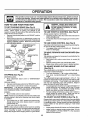
These symbols may appear on your tractor or in literature suppUed with the product, Learn and understand their meaning°
+
BATFERY
CAUTION OR
WARNING
REVERSE
FORWARD
FAST
SLOW
ENGINE ON
ENGINE OFF
OIL PRESSURE
CLUTCH
LIGHTS ON
LIGHTS OFF
FUEL
CHOKE
MOWER HEIGHT
DIFFERENTIAL
LOCK
PARKING BRAKE
LOCKED
UNLOCKED
L
REVERSE
MOWER LIFT
DANGER,
NEUTRAL
ATTACHMENT
CLUTCH ENGAGED
HIGH
LOW
ATTACHMENT
CLUTCH DISENGAGED
PARKING BRAKE
IGNITION
HYDROSTATIC FREE WHEEL
(Hydro Models only)
KEEP HANDS AND FEET AWAY
11
,,,,,,,,,
,,,,,,,,,,,,,,,,,,,,,,,,,,,,,,,,,
,
.................................
OPERATION
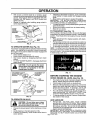
KNOW "(OUR TRACTOR
READ
THIS
OWNER'S
MANUAL
AND SAFETY
RULES
BEFORE
OPERATING
YOUR
TRACTOR
Compare the illustrationswith yourtractor to familiarize yourself with the locations of various controls and adjustments
this manual for future reference,,
CHOKE
CONTROL
LIGHT
SWITCH
POSITION
ATTACHMENT
AMMETER
CLUTCH LEVER
\
Save
LIFT LEVER
PLUNGER
\
ATTACHMENT
LIFT LEVER
©
CLUTCH/
BRAKE
PEDAL
IGNITION
SWITCH
, .
HEIGHT
ADJUSTMENT
KNOB
PARKING
BRAKE
FREEWHEEL
CONTROL
-
i
_
'
' ....
CONTROL
MOTION
LEVER
APPROX.
SPEED
3 MPH
2MPH
1MPH
i.;I
FIG. 7
Our tractors conform to the safety standards of the American National Standards lnstitute_
ATTACHMENT CLUTCH LEVER: Used to engage the
mower blades, or other' attachments mounted to your
tractor.
MOTION CONTROL LEVER: Selects the speed and direction of the tractor_
ATTACHMENT LIFT LEVER: Used to raise and lower the
mower deck or other attachments mounted to your tractor'.
LIFT LEVER PLUNGER: Used to release attachment lift
lever when changing its position..
LIGHT SWITCH: Turns the headlights on and off,
THROTTLE CONTROL:
Used to control engine speed,.
CLUTCH/BRAKE PEDAL: Used for declutching and braking the tractor and starting the engine..
PARKING BRAKE: Locks clutch/brake
brake position._
IGNITION SWITCH:
engine.
pedal into the
HEIGHT ADJUSTMENT KNOB: Used toadjust the mower
cutting height.
FREEWHEEL CONTROL: Disengages transmission for
pushing or slowly towing the tractor with the engine off,.
CHOKE CONTROL:
Used for starting and stopping the
AMMETER: Indicates battery charging (+) or discharging
(-),
Used when starting a cold engine_
12
OPERATION
The operation
in severe eye
or performing
spectacles or
of any tractor can result in foreign objects thrown into the eyes, which can result
damage. Always wear safety glasses or eye shields while operating your tractor
any adjustments or repairs. We recommend a wide vision safety mask over the
standard safety glasses.
Ill;I
HOW TO USE YOUR
TO SET PARKING
Your tractoris equipped with an operator presence sensing
switch,_ When engine is running, any attempt by the
operator to leave the seat without first setting the parking
brake wiIl shut off the engine°
•
Depress clutch/brake pedal into full "BRAKE" position
and hold_
•
PIace parking brake lever in "ENGAGED" position and
release pressure from clutch/brake pedal. Pedal should
remain in "BRAKE" position. Make sure parking brake
will hold tractor secure.
iii
i
iliiii
iiiii
ii ii
ii;i;ii,i;,,i,
PARKING
(See Fig. 8)
(See Fig. 8)
Use choke control whenever you are starting a cold engine_
Do not use to start a warm engine.
•
To engage choke control, pull knob out. Slowly push
knob in to disengage°
TO MOVE FORWARD
Fig. 8)
MOTION CONTROL
LEVER
"BRAKE"
POSITION
CONTROL
TO USE CHOKE CONTROL
ITION
AND BACKWARD
(See
The directionand speed of movement is controlled by the
motion control lever.
° Start tractor with motion control lever in neutral (N)
position
° Release parking brake and clutch/brake pedal°
° Slowly move motion control lever to desired position,
BRAKE
"ENGAGED"
POSITION
TO ADJUST
I
"DISENGAGED"
POSITION
MOWER
CUTTING
HEIGHT
(See Fig. 8)
The cutting height is controlled by turning the height adjustment knob in desired direction,,
° Turn knob clockwise (('-_) to raise cutting height°
° Turn knob counterclockwise (b_-'_) to lower cutting
height.
The cutting height range is approximately 1-1/2" to 4". The
heights are measured from the ground to the blade tip with
the engine not running_ These heights are approximate
and may vary depending upon soil conditions, height of
grass and types of grass being mowed°
o The average lawn should be cut to approximately 2-'I/2
inches during the cool season and to over 3 inches
during hot months, For healthier and better looking
lawns, mow often and after moderate growth°
°
For best cutting performance, grass over 6 inches in
height should be mowed twice. Make the first cut
relatively high; the second to desired heighL
FIG. 8
STOPPING
i i iii
Always operate engine at full throttle.
•
Operating engine at less than full throttle reduces the
battery charging rate,.
•
Full throttle offers the best bagging and mower performance.
"DISENGAGE"
HEIGHT
ADJUSTMENT
KNOB
iiiii
TO USE THROTTLE
ATTACHMENT CLUTCH
LEVER "ENGAGE"
POSITION
CHOKE
CONTROL
CLUTCH!BRAKE
PEDAL "DRIVE"
POSITION
iii
pletely, as described above, before leavCAUTION:
Always position;
stop tractor
coming the operator's
to empty
grass catcher, etc.
BRAKE (See Fig, 8)
THROTTLE
CONTROL
li lili
TRACTOR
(See Fig. 8)
MOWER BLADES = Move attachment clutch Lever to "DISENGAGED"
position°
GROUND DRIVE •
Depress clutch/brake pedal intofull "BRAKE" position,,
•
Move motion control lever to neutral (N) position°
IMPORTANT= THE MOTION CONTROL LEVER DOES
NOT RETURN TO NEUTRAL (N) POSITION WHEN THE
CLUTCH/BRAKE
PEDAL
IS DEPRESSED.,
ENGINE "
Move throttle control to slow position.,
NOTE: Failure to move throttle control to slow position and
aliowing engine to idle before stopping may cause engine
to "backfire",
o Turn ignition key to "OFF" position and remove key.
Always remove key when leaving tractor to prevent
unauthorized use,,
°
Never use choke to stop engine.
NOTE: Under certain conditions when tractor is standing
idle with the engine running, hot engine exhaust gases may
cause "browning" of grass., To eliminate this possibility,
always stop engine when stopping tractor on grass areas,,
TO ADJUST
GAUGE WHEELS
(See Fig, 9)
Gauge wheels are properly adjusted when they are slightly
off the ground when mower is at the desired cutting height
in operating position, Gauge wheels then keep the deck in
proper position to help prevent scalping in most terrain
conditions,,
13
o
Adjust gauge wheels with tractor on a flat level surface,
°
Adjust mower to desired cutting height (See 'q'O ADJUST MOWER CUTTING HEIGHT _' in the Operation
section of this manual)°
, ,,,,,,,,,,,,,,
OPERATION
,,
°
•
With mower in desired height of cut position, gauge
wheels should be assembled so they are slightly off the
ground° Install gauge wheel in appropriate hole with
shoulder bolt, 3/8 washer', and 3/8-16 Iocknut and
tighten securely_
Repeat for opposite side installing gauge wheel in
same adjustment hole..
GAUGE
WHEEL
MOUNTING
BRACKET
SHOULDER
BOLT
FIG. 9
TO OPERATE
MOWER (See Fig. 10)
Your tractor is equipped with an operator presence sensing
switch.. Any attempt by the operator to leave the seat with
the engine running and the attachment clutch engaged will
shut off the engine_
•
Select desired height of cut,
•
Lower mower with attachment lift control.
°
Start mower blades by engaging attachment clutch
control
° TO STOP MOWER BLADES - disengage attachment
clutch control.
,,,,
..........................................
°
If stopping is absolutely necessary, push clutch/brake
pedal quickly to brake position and engage parking
brake,
•
Move motion control lever to neutral (N) position.
IMPORTANT; THE MOTION CONTROL LEVER DOES
NOT RETURN TO NEUTRAL (N) POSITION WHEN THE
CLUTCH/BRAKE PEDAL IS DEPRESSED.
• To restartmovement, slowly release parking brake and
clutch!brake pedal..
•
Slowly move motion control lever to slowest setting..
•
Make all turns slowly_
TO TRANSPORT
(See Fig, 11)
When pushing or towing your' tractor, be sure to disengage
transmission by placing freewheel control in freewheeling
position. Free wheel control is located at the rear drawbar
of tractor..
= Raise attachment lift to highest position with attachment lift control.
•
Pult freewheel control knob out and hold in position by
inserting retainer spring intoforward hole of control rod.,
•
Do not push or tow tractor at more than two (2) MPH.
• To reengagetransmission, reverse above procedure°
NOTE: To protect hood from damage when transporting
your tractoron a truck or a trailer, be sure hood isclosed and
secured to tractor. Use an appropriate means of tying hood
to tractor (rope, cord, etc_).
CAUTION: Do not operate the mower
without either the entire grass catcher,
on mowers so equipped, or the discharge guard in place,
ATTACHMENT CLUTCH
LEVER "ENGAGED"
POSITION
FIG. 11
ATTACHMENT LIFT
LEVER HIGH
POSITION
,/_
BEFORE
=
•
o
•
DISCHARGE
GUARD
•
FIG. 10
TO OPERATE
°
•
ON HILLS
The engine inyour tractor has been shipped, from the
factory, already filled with summer weight oil
Check engine oil with tractor on level ground.
Remove oil fill cap/dipstick and wipe clean, reinsertthe
dipstick and screw cap tight, wait for a few seconds,
remove and read o[I level If necessary, add oil until
"FULL" mark on dipstick is reached. Do not overfill.
For cold weather operation you should change oil for
easier starting (See "OIL VISCOSITY CHART" in the
Customer Responsibilities section of this manual).
To change engine oil, see the Customer Responsibilities section in this manual.
ADD GASOLINE
Fill fuel tank.. Use fresh, clean, regular unleaded
gasolinewith a minimum of 87 octane.. (Use of leaded
gasoline will increase carbon and lead oxide deposits
and reduce valve life)_ Do not mix oil with gasoline.
Purchase fuel in quantities that can be used within 30
Choose the slowest speed before starting up or down
days to assure fuel freshness_
hills.
IMPORTANT: WHEN OPERATING iN TEMPERATURES
Avoid stopping or changing speed on hills.
BELOW 32°F(0_C), USE FRESH, CLEAN WINTER GRADE
If slowing is necessary, move throttle control lever to
GASOLINE TO HELP INSURE GOOD COLD WEATHER
slower position_
14 STARTING
A
°
THE ENGINE
CHECK ENGINE OIL LEVEL (See Fig. 15)
LOW
POSITION
POSITION
HEIGHT
ADJUSTMENT
KNOB
STARTING
CAUTION: Do not drive up or down
hills with slopes greater than 15° and
do no t drive across any slope.
I
I
I
•
OPERATION
WARNING:
Experience indicates that alcohol blended
fuels (called gasoho! or using ethanol or methanol) can
attract moisture which leads to separation and formation of
acids during storage. Acidic gas can damage the fuel
system of an engine while in storage To avoid engine
problems, the fue! system should be emptied before storage of 30 days or longer. Drain the gas tank, start the
engine and let it run until the fuel lines and carburetor are
empty. Use fresh fuel next season See Storage Instructions for additional information.
Never use engine or
carburetor cleaner products in the fuel tank or permanent
damage may occur°
I_
filler neck. Do not overfill. Wipe off any
spilled oil or fuel. Do not store, spill or
CAUTION: Fill to bottom of gas tank
use gaso!ine near an open flame.
TO START ENGINE (See Fig. 8)
When starting the engine for the first time or if the engine
has run out of fuel, it will take extra cranking time to move
fuel from the tank to the engine.
•
Be sure freewheel control is in the transmission engaged position.
•
Sit on seat in operating position, depress clutch/brake
pedal and set parking brake°
•
Place motion control lever in neutral (N) position,
•
Move attachment clutch to "DISENGAGED" position
,
Move throttle control to fast position
°
Pull choke control out for a cold engine start attempt.
For a warm engine start attempt the choke control may
not be needed°
Note: Before starting, read the warm and cold starting
procedures below°
o Insert key into ignition and turn keyclock"wise to"START"
position and release key as soon as engine starts. Do
not run starter continuously for more than fi_en seconds per minute. If the engine does not start after
several attempts, push choke control in, wait a few
minutes and try again. If engine still does not start, pull
the choke control out and retry,
WARM WEATHER STARTING (50° F and above)
° When engine starts, slowly push choke control in until
the engine begins to run smoothly. If the engine starts
to run roughly, pull the choke control out slightly for a
few seconds and then continue to push the control in
slowly.
° The attachments and ground drivecan nowbe used. If
the engine does not accept the load, restart the engine
and allow it to warm up for one minute using the choke
as described above°
COLD WEATHER STARTING (50 ° F and below)
° When engine starts, slowly push choke control in until
the engine begins to run smoothly. Continue to push
the choke control in small steps allowing the engine to
accept small changes in speed and load, until the
choke control is fully in. If the engine starts to run
roughly, pull the choke control out slightly for a few
seconds and then continue to push the control tn
slowly. This may require an engine warm-up period
from several seconds to several minutes, depending
on the temperature°
HYDROSTATIC TRANSMISSION WARM UP
•
Before driving the unit in cold weather, the transmission should be warmed up as follows:
• Be sure the tractor is on level ground.
• Place the motion control lever in neutral.
Release the parking brake and let the clutch/brake
slowly return to operating position.
° Allow one minute for transmission to warm up.
This can be done during the engine warm up
pedod.
° The attachments can be used during the engine warmup period after the transmission has been warmed up
and may require the choke control be pulled out slightly.
NOTE: If at a high altitude (above 3000 feet) or in cold
temperatures (below 32 F) the carburetor fuel mixture may
need to be adjusted for best engine performance. See "TO
ADJUST CARBURETOR" in the Service and Adjustments
section of this manual.
PURGE TRANSMISSION
CAUTION: Never engage or disengage
freewheel lever while the engine is runnlng_
t
!
To ensure proper operation and performance, it is recommended that the transmission be purged before operating
tractor for the first time. This procedure will remove any
trapped air inside the transmission which may have developed during shipping of your tractor.
IMPORTANT; SHOULD YOUR TRANSMISSION REQUIRE
REMOVAL FOR SERVICE OR REPLACEMENT,
IT
SHOULD BE PURGED AFTER REINSTALLATION
BEFORE OPERATING THE TRACTOR
= Place tractor safely on level surface with engine off and
parking brake set.
•
Disengage transmission by placing freewheel control
in freewheeling position (See '`TO TRANSPORT" in
this section of manual).
•
Sitting inthe tractor seat, start engine, After the engine
is running, move throttle control to slow position. With
motion control lever in neutral (N) position, slowly
disengage clutch/brake pedal..
° Move motion control lever to full forward position and
hold for five (5) seconds. Move lever to full reverse
position and hold for five (5) seconds. Repeat this
procedure three (3) times.
NOTE: During this procedure there will be no movement of
drive wheels.. The air isbeing removed from hydraulic d rive
system
°
Move motion control lever to neutral (N) position_ Shutoff engine and set parking brake..
°
Engage transmission by placing freewheel control in
driving position (See 'TO TRANSPORT' in this section
of manual).
Sitting in thetractor seat, start engine. After the engine
is running, move throttle control to half (1/2) speed.
With motion control lever in neutral (N) position, slowly
disengage clutch/brake pedal.
°
Slowly move motion control lever forward, after the
tractor moves approximately five (5) feet, slowly move
motion control lever to reverse position. After the
tractor moves approximately five (5) feet return the
motion control lever to the neutral (N) position, Repeat
this procedure with the motion control lever three (3)
times.
•
Your tractor is now purged and now ready for normal
operation..
15
OPERATION
MULCHING
MOWING TIPS
.
Tire chainscannot be used when the mower housing is
attached to tractor.
•
Mower' should be properly leveled for best mowing
performance.. See q'O LEVEL MOWER HOUSING" in
the Service and Adjustments section of this manual°
The Ieft hand side of rnower should be used for trimruing
Drive so that clippings are discharged onto the area
that has been cute Have the cut area to the right of the
tractor. This will result in a more even distribution of
clippings and more uniforrn cutting.
•
,
o
°
•
•
•
MOWING TIPS
IMPORTANT:
FOR BEST PERFORMANCE, KEEP
MOWER HOUSING FREE OF BUILT-UP GRASS AND
TRASH., CLEAN AFTER EACH USE.
•
The special mulching blade will recut the grass clippings many times and reduce them in size so that as
they fall onto the lawn they will disperse into the grass
and not be noticed. Also, the mulched grass will
biodegrade quickly to provide nutrients for the lawn.
Always mulch with your highest engine (blade) speed
as this will provide the best recutting action of the
blades.
•
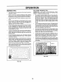
When mowing large areas, start by turning to the right
so that clippings will discharge away from shrubs,
fences, driveways, etc. After one or two rounds, mow
in the opposite direction making left hand turns until
finished (See Fig° t2A )..
Avoid cutting your iawn when it iswet.. Wet grass tends
to form clumps and interferes with the mulching action.
The best time to mow your lawn is the early afternoon.
At this time the grass has dried and the newly cut area
wilt not be exposed to the direct sun.
•
if grass is extremely tall, it should be mowed twice to
reduce load and possible fire hazard from dried clippings. Make first cut relatively high; the second to the
desired height.
Forbest results,adjust the mower cutting height so that
the mower cuts off only the top one-third of the grass
blades (See Fig. 12B). For extremety heavy mulching,
reduce your' width of cut and mow slowly.
°
Certain types of grass and grass conditions may require that an area be mulched a second time to completefy hide the clippings. When doing a second cut,
mow across or perpendicular to the first cut path_
Change your cutting pattern from week to week. Mow
north to south one week then change to east to west the
next week_ This will help prevent matting and graining
of the lawn.
Do not mow grass when it is weL Wet grass will ptug
mower and leave undesirable clumps.. Allow grass to
dry before mowing.
Always operate engine at full throttle when mowing to
assure better mowing performance and proper discharge of material Regulate ground speed by selecting a low enough gear' to give the mower cutting
performance as well as the quality of cut desired..
•
When operating attachments, select a ground speed
that will suit the terrain and give best performance of
the attachment being used
'I MAX 1/3
f
1
i!,_! \
FIG. 12B
FtGo12A
16
CUSTOMER
RESPONSIBILITIES
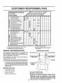
ASYOU
COMPLETE
REGULARSERVICE
_/_._#"
_'_
Check Brake Operation
_
Check Tire Pressure
_
Check for LOOse Fasteners
a
Sharpen/Replace
Mower Blades
Lubrication Chart
C
Check BatterYLeve!tRecharge
0
Clean Battery and Terminals
a
CheckTransax[eCoofing
-_
6_
6_
"
"
6/7
!_
1_4
_
i
Adjust Blade Belt(s) Tension
_si
Adjust Motion Drive Bell(s) Tension
_si
Check Engine Oil Levei
if
....
Change
Eng O,
oo
E
Clean Air Filte r .......
N
Clean Air Screen
G
Inspect Muffler/Spark
.......
SERVICE DATES
V',.........
t_2
_i:
',
Arrester
_
,
..........
....
.......
t4 #
I
Replace Oil Filter (If equipped)
_,2
N
Clean Engine Cooling Fins
Replace Spark PIug
t##'2
6##'
Replace Air Filter Paper Cartridge
6f2
6/
Replace Fuel Filter
1 - Change more often when operating under a heavy Iced or in high ambient temperatures
2 - Service more often when operating }n dfrty or dusty conditions
3 - tf equipped with oil filter, change oll every 50 hours
4 - Reptece blades mere otten when mowing in sandy soil
GENERAL RECOMMENDATIONS
5 - If equipped with adIustable system
6- Not required if equipped wtth matntenance_free battery
7 - Tighten front axle pivot bolt to 35 ft,Abs, maximum,
Do not overttghten,,
LUBRICATION
The warranty on this tractor does not cover items that have
been subjected to operator abuse or negligence, To
receive full value fromthe warranty, operator must maintain
tractor as instructed in this manual,
(_) SPINDLE ZERK
(_
Some adjustments will need to be made periodically to
properly maintain your tractor,
BEARING
ZERK
All adjustments in the Service and Adjustments section of
this manual should be checked at least once each season.
CHART
®
FRONT WHEEL (_)
BEARING ZERK
®
Once a year you should replace the spark plug, clean
or replace air filter, and check blades and belts for
wear, A new spark plug and clean air filter assure
proper air-fuel mixture and help your engine run better
and last Ionger_
®
CLUTCH
PIVOT(S)
BEFORE EACH USE
•
Check engine oil level.
•
Check
•
•
Check tire pressure,,
Check for loose fasteners_
brake
operation.
(_
SAE 30 OR 10W30 MOTOR OIL
(_) GENERAL PURPOSE GREASE
17
® REFER TO CUSTOMER RESPONSIBILITIES "ENGINE" SECTION
IMPORTANT:
DO NOT OIL OR GREASE THE PIVOT POINTS
WHICH HAVE SPECIAL NYLON BEARINGS
VtSCOUS LUBRICANTS WILL ATTRACT DUST AND DIRT THAT WILL SHORTEN
THE LIFE OF THE SELF-LUBRICATING
BEARINGS,
IF YOU
FEEL THEY MUST BE LUBRICATED,
USE ONLY A DRY, POWDERED GRAPHITE TYPE LUBRICANT SPARINGLY,
iilu
iiiiiiiiiiiiiiiiiiiiii
CUSTOMER
iiii
i
ii
i
i
i1,111111,11111u
iii
i
ii
i
i
IIIILIIIIIIIIIIIIIIIII
RESPONSIBILITIES
TRACTOR
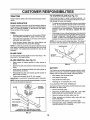
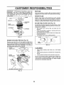
TO SHARPEN
Always observe safety rules when performing any maintenance.
Care should be taken to keep the blade balanced° An
unbalanced blade willcause excessive vibrationand eventual damage to mower and engine.
BRAKE OPERATION
•
If tractor'requires more than six (6) feet stopping distance
at high speed in highest gear, then brake must be adjusted.
(See 'q'O ADJUST BRAKE" in the Service and Adjustments section of this manual).
•
TIRES
•
=
•
•
Maintain proper' air pressure in all tires (See "PRODUCT SPECIFICATIONS" on page 3 of this manual)_
Keep tires free of gasoline, oil, or insect control chemicals which can harm rubber.
The blade can be sharpened with a file oron a grinding
wheel° Do not attempt to sharpen while on the mower.
To check blade balance, you will need a 5/8" diameter
steel bolt, pin, ora cone balancer. (When using a cone
batancer, follow the instructions supplied with balancer).
Slidebladeontoanunthreadedportionofthesteelbolt
or pin and hold the bolt or pin parallel with the ground.
If blade is balanced, it should remain in a horizontal
position° if either end of the blade moves downward,
sharpen the heavy end until the blade is balanced.
NOTE: Do not use a nail for'balancing blade. The lobes of
the center hole may appear to be centered, but are not,,
Avoid stumps, stones, deep ruts, sharp objects and
other hazards that may cause tire damager
NOTE: To seal tire punctures and prevent flat tires due to
slow leaks, tire sealant may be purchased from your local
parts dealer. Tire sealant also prevents tire dry rot and
corrosion_
BLADE
BLADE (See Fig. 14)
CENTER HOLE
/
/
CARE
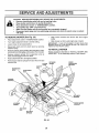
For best results mower' blades must be kept sharp° Replace bent or damaged blades.,
BLADE REMOVAL
(See Fig. 13)
°
Raise mower' to highest position to allow access to
blades°
-
Remove hex bolt, lock washer and flat washer securing
blade.
°
Install new or resharpened blade with trailing edge up
towards deck as shown,.
°
Reassemble hex bolt, lock washer and flat washer in
exact order as shown_
FIG. 14
BATTERY
Your tractor has a battery charging system which is sufficient for' normal use. However, periodic charging of the
battery with an automotive charger will extend its life.
°
Tighten boit securely (30-35 FL Lbs., torque)_
IMPORTANT: BLADE BOLT IS GRADE 8 HEATTREATED_
NOTE" We do not recommend sharpening blade- but ifyou
do, be sure the blade is balanced_
BLADE
°
°
Keep battery and terminals clean.
Keep battery bolts tighL
•
Keep small vent holes open.
•
Recharge at 6-10 amperes for' 1 hour.
TO CLEAN BATTERY AND TERMINALS
Corrosion and dirton the battery and terminals can cause
the battery to "leaW' power_
MANDREL
TRAILING EDGE
•
•
Remove terminal guard.
Disconnect BLACK battery cable first then RED
battery cable and remove battery from tractor.
•
•
Rinse the battery with plain water and dry°
Clean terminals and battery cable ends with wire
brush until bright.,
°
•
Coat
terminals with grease or petroleum jeUy.
t
Reinstall battery (See "CONNECT BATTERY" in the
Assembly section of this manual).
FLAT WASHER
HEX BOLT
"A GRADE 8 HEAT TREATED BOLT' CAN BE
IDENTIRED BY SIX LINES ON THE BOLT HEAD,
FIG. 13
18
i
i
i i
,i,,lllli,ii,,i,l,,llll
LJTIES
CUSTOME
................................
ll,,ll,,lllll
,_ i i
,i ii
III'I'I"H
V-BELTS
=
Check V-belts for deterioration and wear after 100 hours of
operation and replace if necessary° The belts are not
adjustable, Replace belts if they begin to slip from wear,
-
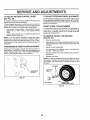
TRANSAXLE
COOLING
o
The fan and cooling fins of transmission should be kept
clean to assure proper cooling°
I II
I
II
I IIII IIlllll' _ll 'Ill ',ll ",l'l",,'l',l
After oil has drained completely, replace oil drain plug
and tighten securely._
Refill engine with oil through oil fill dipstick tube. Pour
slowly. Do not overfill. For approximate capacity see
"PRODUCT SPECIFICATIONS" on page 3 of this
manual
Use gauge on oil fill cap/dipstick for checking level. Be
sure dipstick cap is hghtened securely for accurate
reading° Keep oil at "FULU' line on dipstick,.
Do not attempt to clean fan or transmission while engine is
running or while the transmission is hot.
•
Inspect cooling fan to be sure fan blades are intactand
clean.
=
Inspect cooling fins for dirt, grass clippings and other
materials, To prevent damage to seals, do not use
compressed air or high pressure sprayer to clean
cooling fins,
TRANSAXLE
AIR SCREEN
OIL
DRAIN
PLUG
OIL FELL
CAP/D|PSTSICK
PUMP FLUID
The transaxle was sealed at the factory and fluid maintenance isnot required for the life ofthe transaxle. Should the
transaxle ever leak or require servicing, contact your nearest authorized service center/department.
FIG. 16
CLEAN AIR SCREEN (See Fig. 16)
LUBRICATION
Air screen must be kept free of dirt and chaff to prevent
engine damage from overheating. Clean with a wire brush
or compressed air to remove dirt and stubborn dried gum
fibers..
Only use high quality detergent oil rated with API service
classification SF, SG or SH. Select the oil's SAE viscosity
grade according to your expected operating temperature,
AIR FILTER (See Fig. 17)
ENGINE
SAE VISCOSITY
=F
"204
°c -3o"
0°
-2oo
30 _
-ioo
TEMPERAT',JRE:RANGE
32 °
Your engine wile not nm properly using a dirty air filter.
CIean the foam pre-cleaner after every 25 hours of operation or every season,, Service paper cartridge every 100
hours of operation or every season, whichever occurs first°
GRADES
4(3=
,,, ,,_............
oo
ANTiciPATED
_
60"
Service air cleaner more often under dusty conditions,.
to,
80; ...............t00 =
_o_
3o°
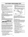
= Remove knob(s) and cover.
TO SERVICE PRE-CLEANER
4o°
BEFOR E NEXT, O,!,L,ICHANGE
FIG. 15
•
•
Slide foam pre-cleaner off cartridge.
Wash it in liquid detergent and water.
°
Squeeze it dry in a clean cloth.
=
Saturate it in engine oil.. Wrap it in clean, absorbent
cloth and squeeze to remove excess oil,.
Change the oil after every 25 hours of operation or at least
once a year ifthe tractor is not used for25 hours in one year,
°
•
If very dirty or damaged, replace pre-cleaner.
Reinstall pre-cleaner over cartridge.
Check the crankcase oil level before starting the engine
and after each eight (8) hours of operation,. Tighten oil fill
cap/dipstick securely each time you check the oil level.
°
Reinstall cover and secure with knob(s)o
TO SERVICE CARTRIDGE
•
Remove wing nuts and cartridge plate
TO CHANGE ENGINE OIL (See Figs.. 15 and 16)
°
Carefully remove cartridge to prevent debris from entering carburetor°
•
Clean cartridge bytapping gently on flat surface. If very
dirty or damaged, replace cartridge.
Reinstall cartridge plate, wing nuts, precleaner, cover
and secure with knob(s),.
NOTE: Although multi-viscosity oils (5W30, 10W30 etc..)
improve starting in cold weather, these multi-viscosity oils
will result in. increased oil consumption when used above
32°F. Check your engine oil level more frequently to avoid
possible engine damage from running low on oil.
Determine temperature range expected before oil change.
All oil must meet API service classification SF, SG or SH.
.
Be sure tractor is on level surface.
•
•
Oil will drain more freely when warm,.
Catch oil in a suitable container,
°
Remove oil fill cap/dipsticko Be careful not to allow dirt
to enter the engine when changing oil.
Remove drain plug.
°
•
19
SIBILITIES
CUSTOMER
MUFFLER
IMPORTANT:
PETROLEUM
SOLVENTS,
SUCH AS
KEROSENE,
ARE NOT TO BE USED TO CLEAN THE
CARTRIDGE.
THEY MAY CAUSE DETERIORATION
OF
THE CARTRIDGE,
DO NOT OIL CARTRIDGE°
DO NOT
USE
PRESSURIZED
AIR TO CLEAN
OR DRY
CARTRIDGE.
inspect and replace corroded muffler and spark arrester (if
equipped) as it could create a fire hazard and/or damage.
SPARK PLUGS
Replace spark plugs at the beginning of each mowing
season or after every 100 hours of operation, whichever
occurs first, Spark pfug type and gap setting are shown in
"PRODUCT SPECIFICATIONS" on page 3 of this manual..
KNOB
PLATE
IN-LINE FUEL FILTER
FOAM
PR
(See Fig. 19)
The fue! filter should be replaced once each season,, iffuel
filter becomes clogged, obstructingfuel flow to carburetor,
replacement is required.
* With engine coo], remove filter and plug fuel line
sections_
.
Place new fuel filter in position in fuel line with arrow
pointing towards carburetor.
.
Be sure there are no fuel line leaks and clamps are
properly positioned..
o Immediately wipe up any spilled gasoline°
AIR SCREEN
CARTRIDGE
FIG. 17
ENGINE
COOLING
CLA_LAMP
FINS (See Fig. 18)
Remove any dust, dirt or oil from engine cooting fins to
prevent engine damage from overheating°Air guide covers
must be removed., Remove side panels and hood (See "TO
REMOVE HOOD AND GRILL ASSEMBLY" in the Service
and Adjustments section of this manual)._
FUEL
/
FILTER -
\
/'j/
/
FIGo 19
CLEANING
COVER
Clean engine, battery, seat, finish, etco of all foreign
matter.
•
Keep finished surfaces and wheels free of all gasoline,
oil, etc..
= Protect painted surfaces with automotive type wax.
We do not recommend using a garden hose to clean your
tractor unless the electrical system, muffler, air filter and
carburetor are covered to keep water ouL Water in engine
can result in a shortened engine life.
ENGINE
COOL|NG FINS
AIR GUIDE
•
(BOTH
SIDES]
FIG. 18
2O
ii
SERVICE AND ADJUSTMENTS
CAUTION; BEFORE PERFORMING ANY SERVICE OR ADJUSTMENTS:
o
Depress clutch/brake pedal fully and set parking brake.
o
Place motion control lever in neutral (N) position.
o
Place attachment clutch in "DISENGAGED" position,
o
Turn ignition key "OFF" and remove key.
o
Make sure the blades and all moving parts have completely stopped.
o
Disconnect spark plug wire from spark plug and place wire where it cannot come in contact
with plug,
TO REMOVE
o
Place attachment clutch in "DISENGAGED" position°
o
°
Turn height adjustment knob to lowest setting.,
Lower mower to its lowest position,.
,,
Disconnect clutch rod from clutch lever by removing
retainer spring.,
Remove retainer spring holding anti-swaybar to chassis bracket and disengage anti-swaybar from bracket,
-
Slide mower forward and remove belt from engine
pulley,
•
Slide mower out from under right side of tractor.,
IMPORTANT: IF AN ATTACHMENT OTHER THAN THE
MOWER DECK IS TO BE MOUNTED ON THE TRACTOR,
REMOVE THE FRONT LINKS,,
MOWER (See Fig. 20)
,,
°
Remove retainer springs from suspension arms at
deck and disengage arms from deck.,
°
Raise attachment lift to its highest position,,
°
Remove two retainer springs from each front link and
remove links,
TO INSTALL
Follow procedure described in "INSTALL MOWER AND
DRIVE BELT" in the Assembly section of this manual,
CLUTCH
LEVER
SUSPENSION
ARMS
MOWER
RETAINER
SPRING
FRONT
SUSPENSION
BRACKET
CLUTCH
ROD
ADJUSTMENT
NUTS
ENGINE
LIFT
LINKS
CHASSIS
BRACKET
LINKS
RETAINER
SPRINGS
FRONT MOWER
BRACKET
RETAINER
SPRING
ANTI-SWAY
BAR
RETAINER
SPRINGS
FIG. 20
21
SERVICE AND ADJUSTMENTS
TO LEVEL
MOWER
HOUSING
FRONT_TO-BACK ADJUSTMENT (See Figs_ 23 and 24)
IMPORTANT;
Adjust the mower while tractor is parked on level ground or
driveway. Make sure tires are properly inflated .(See
"PRODUCT SPECIFICATIONS" on page 3 of this manual),
If tires are over or under'inflated, you will not properly adjust
your mower_
SIDE-TO-SiDE ADJUSTMENT (See Figs_ 21 and 22)
= Raise mower to its highest position_
°
At the midpoint of both sides of mower, measure height
from bottom edge of mower to ground_ Distance"A" on
both sides of mower should be the same or within 1/4"
of each other_
"
tf adjustment is necessary, make adjustment on one
side of mower only..
To raise one side of mower, tighten lift linkadjustment
nut on that side..
•
°
To lower one side of mower, loosen lift link adjustment
nut on that side.
NOTE: Each full turn of adjustment nut wiII change mower
height about 1/8".
°
Recheck measurements after-adjusting..
BOTTOM EDGE
OF MOWER TO
GROUND
DECK
MUST
BE LEVEL
SiDE-TO-SIDE,
BOTTOM EDGE
OF MOWER TO
GROUND
._ _=.._
,
_
MANDREL
FIG. 21
SUSPENSION
ARM
FIG. 23
BOTH FRONT LINKS MUST BE EQUAL tN LENGTH
UFTLINK
ADJUSTMENT
IF
THE FOLLOWING FRONT-TO-BACK ADJUSTMENT IS
NECESSARY, BE SURE TO ADJUST BOTH FRONT LINKS
EQUALLY SO MOWER WILL STAY LEVEL SIDE-TOSIDE.
To obtain the best cutting results, the mower housing
should be adjusted so that the front is approximately 1/8" to
1/2" lower than the rear when the mower' is in its highest
position_
Check adjustment on right side of tractor.. Measure distance "D" directly in front and behind the mandrel at bottom
edge of mower housing as shown.
°
Before making any necessary adjustments, check that
both front links are equat in length. Both links should be
approximately 10-3/8'L
.
if links are not equal in length, adjust one link to same
length as other link.
•
To lower front of mower' loosen nut "E" on both front
links an equal number of turns.
•
When distance "D" is 1/8" to 1/2" lower at front than
rear, tighten nuts "F" against trunnion on both front
links_
• To raise
front
ofmower,loosennut"F"from
trunnion
on
bothfront
links,
Tightennut"E"on bothfrontlinksan
equalnumber ofturns.
° When distance "D" is 1/8" to 1/2" lower at front than
rear, tighten nut "F" against trunnion on both front links..
•
Recheck side-to-side adjustmenL
NUT
FIG. 22
NUT "E"
NUT
FRONT LINKS
22
TRUNNION
FIG. 24
ii
....................................
SERVICE AND ADJUSTMENTS
i ,111iii i m
TO REPLACE
MOWER
DRIVE
BELT
TO REPLACE
(See Fig. 26)
MOWER DRIVE BELT REMOVAL (See Fig 25)
•
Park tractor on a level surface. Engage parking brake.
Disengage attachment clutch control.,
•
Remove four screws from LH, mandrel cover and
remove cover.,
-
Roll belt over the top of L.H. mandrel pulley.
-
Remove belt from engine pulley,,
•
Remove belt from idler pulleys.
•
Remove any dirt or grass clippings which may have
accumulated around mandrels and entire upper deck
surface.
m
Ik I
II I I I
MOWER
I1'11
..................... I I I
BLADE
DRIVE
I
BELT
Park the tractor on level surface° Engage parking brake,
e
Remove mower drive belt (See'q-O REPLACE MOWER
DRIVE BELT' in this section of this manual).
o
Remove mower (See "TO REMOVE MOWER" in this
section of this manual),,
I
Remove four screws from R,H mandrel cover and
remove cover,.
o
Disconnect secondary clutch rod from pivot rod by
removing retainer spring,
o
Carefully roll belt off R.,H. mandrel pulley,,
Check primary idler arm and two idlers to see that they
rotate freely,,
o
Remove belt from center mandrel pulley, idler pulley,
and L.H mandrel pulley.
MOWER DRIVE BELT INSTALLATION (See Fig, 25)
•
Install belt in both idlers° Make sure belt is in both belt
keepers at the idlers as shown.,
o
Remove any dirt or grass which may have accumulated around mandrels and entire upper deck surface,
o
Check secondary idler arm and idler to see that they
rotate freely.,
o
Be sure spring is hooked in secondary idler arm and
sway-bar bracket,
o
Install new belt in lower groove of L.H. mandrel pulley,
idler pulley, and center mandrel pulley as shown.
Roll belt over R.H mandrel pultey. Make sure belt is in
all grooves properly,
•
°
•
Install new belt onto engine pulley,
Roll belt into upper groove of L_H. mandrel puiley_
-
Carefully check belt routing making sure belt is in the
grooves correctly and inside belt keepers.,
Reassemble L,H. mandrel cover.
o
o
SCREWS
°°v,.X !\,
IDLER
PULLEYS
ENGINE
PULLEY
°
o
o
Reconnect secondary clutch rod to pivot rod with
retainer spring_
Reinstall R,Ho mandrel cover,
Reinstall mower to tractor (See "INSTALL MOWER
AND DRIVE BELT" in the Assembly section of this
manual)°
Reassemble mower drive belt (See "TO REPLACE
MOWER DRIVE BELT" in this section of this manual),
L,H,, MANDREL
MOWER
BLADE
DRIVE BELT
CENTER
MANDREL
SECONDARY
IDLER ARM
MANDREL
\
SPRING
MOWER
DRIVE
BELT
BELT
KEEPERS
FIG. 25
SWAY BAR
BRACKET
IDLER
PULLEY
FIG. 26
23
SCREW
SERVICE AND ADJUSTMENTS
TO ADJUST
TO REPLACE
(See Fig. 28)
BRAKE (See Fig. 27)
Your tractor is equipped with an adjustable brake system
which is mounted on the side of the transaxle,.
Park the tractor on level surface_ Engage parking brake_
For assistance, there is a belt installation guide decal on
bottom side of left footrest,.
If tractor requires more than six (6) feet stopping distance
at high speed in highest gear, then brake must be adjusted.,
•
•
Depress clutch/brake pedal and engage parking brake,
Measure distance between brake operating arm and
nut "A" on brake rod,.
°
tf distance is other than 1-3/4", loosen jam nut and turn
nut "A" until distance becomes 1-3/4". Retighten jam
nut against nut "A",,
Road test tractor for proper stopping distance as stated
above,, Readjust if necessary, if stopping distance is
still greater than six (6) feet in highest gear, further
maintenance is necessary, Contact your nearest authorized service center?department,
•
MOTION DRIVE BELT
•
Remove mower (See "TO REMOVE MOWER" in this
section of this rr_anual,)
•
•
Remove upper belt keeper.
Remove belt from stationary idler and crutching idter_
•
Pull belt slack toward rear of tractor° Carefully remove
belt upwards from transmission input pulley and over
cooling fan blades_
Pull belt toward front of tractor and remove downward
from around engine pulley,,
•
°
Install new belt by reversing above procedure
IMPORTANT: MAKE SURE UPPER BELT KEEPER IS
POSITIONED PROPERLY BETWEEN LOCATOR TABS,
WITH PARKING BRAKE "ENGAGED"
NUT "A"
NUT
PULLEY
OR
TABS
CLUTCHING
IDLER
UPPER BELT
KEEPER
IDLER
ARM
TRANSMISSION"
INPUT PULLEY
DO NOT TOUCH THIS NUT. IF FURTHER BRAKE ADJUST_
MENT IS NECESSARY CONTACT YOUR NEAREST AUTHORIZED SERVICE CENTER/DEPARTMENT
FIG. 27
FIG. 28
24
SERVmCE AND ADJUSTMENTS
TO ADJUST
MOTION
CONTROL
TO ADJUST
LEVER
WHEEL
ALIGNMENT
If steering wheel crossbars are not horizontal (left to right)
when wheels are positioned straight forward, remove steering wheel and reassemble per instructionsin the Assembly
section of this manual.
(See Fig. 29)
The motion control lever has been preset at the factory and
adjustment should not be necessary_
If for any reason the motion control lever will not hold its
position while at a selected speed, it may be adjusted at the
friction pack located on the right side of transmission,.
.
Park tractor on level surface.. Stop tractor by turning
ignition key to "OFF" position, and engage parking
brake,.
•
Adjust motion control lever by tightening adjustment
tocknut one half (1/2) turn.
NOTE: If for any reason the effort to move the motion
control lever becomes too excessive, reverse the above
adjustment procedure by loosening locknut 1/4 to 1/2 turn
Road test tractor after adjustment and repeat procedure if
necessary.
TRANSMISSION
STEERING
FRONT WHEEL TOE-IN/CAMBER
The front wheel toe-in and camber are not adjustable on
your tractor, if damage has occurred to affect the front
wheel toe-in or camber, contact your nearest authorized
service center/department,
TO REMOVE
WHEEL
FOR
REPAIRS
(See Fig. 30)
REMOVAL/REPLACEMENT
Should your transmission require removal for service or
replacement, it should be purged after reinstallation and
before operating the tractor. See "PURGE TRANSMISSION" in the Operation section of this manual
•
Block up axle securely.
-
Remove axle cover, retaining ring and washers to allow
wheel removal (rear wheel contains a square key - Do
not lose).
•
Repair tire and reassemble.
•
On rear wheels onty: align grooves in rear wheel hub
and axle. Insert square key.
-
Replace washers and snap retaining ring securely in
axle groove_
°
Replace axle cover.
NOTE: To seal tire punctures and prevent flat tires due to
slow leaks, tire sealant may be purchased from your local
parts dealer. Tire sealant also prevents tire dry rot and
corrosion,.
WASHERS
RETAINING
RING
ADJUSTMENT
LOCKNUT
FIG. 29
!
AXLE COVER
_,,
SQUARE
KEY
(REAR WHEEL ONLY)
FIG. 30
25
I
I
III
II
L
k
II
J
ILl
Iklllll
llllllklllll[lJlJlJllJ
ICE AND ADJUSTM
TO START ENGINE WITH A WEAK BATTERY
TO REPLACE
(See Fig. 31)
Replace with 30 amp automotive4ype plug-in fuse. The
fuse holder is located behind the dash..
..........................
iii
CAUTION:
I
III
I
FUSE
Lead-acid batteries gen'er-
TO REMOVE
and smoking materials away from batate explosive gases. Keepsparks, flame
teries. Always wear eye protection
when around batteries.
HOOD AND GRILL ASSEMBLY
(See Fig. 32)
•
Raise hood.
•
Unsnap headlight wire connector.
•
Stand in front of tractor. Grasp hood at sides, tilt toward
engine and lift off of tractor,
•
To replace, reverse above procedures.
If your battery is too weak to start the engine, it should be
recharged_
If "jumper' cables" are used for emergency
starting, follow this procedure:
IMPORTANT:
YOUR TRACTOR
IS EQUIPPED WITH A
12 VOLT NEGATIVE GROUNDED SYSTEM. THE OTHER
VEHICLE
MUST ALSO BE A 12 VOLT NEGATIVE
GROUNDED SYSTEM.
DO NOT USE YOUR TRACTOR
BATTERY TO START OTHER VEHICLES.
HOOD
TO ATTACH JUMPER CABLES •
Connect each end of the RED cable to the POSITIVE
(+) terminal of each battery, taking care not to short
against chassis.
°
Connect one end of the BLACK cable to the NEGATIVE (-) terminal of fully charged battery°
°
Connect the other end of the BLACK cable to good
CHASSIS GROUND, away from fuel tank and battery.
HEADLIGHT
WIRE
CONNECTOR
TO REMOVE CABLES, REVERSE ORDER °
BLACK cable first from chassis and then from the fully
charged battery.
•
RED cable last from both batterie&
FIG. 32
ENGINE
"POSITIVE"
"NEGATIVE"
(+)
TO ADJUST THROTTLE
(See Fig. 33)
(-)
CONTROL
CABLE
The throttle control has been preset at the factory and
adjustment should not be necessary. Check adjustment as
described below before loosening cable. If adjustrnent is
necessary, proceed as follows:
•
With engine not running, move throttle control lever to
fast position°
•
Check that swivel is against side of quarter circle. If it
is not, loosen cable clamp screw and pull cable back
until swivel is against quarter' circle.. Tighten cable
clamp screw securely°
FIG. 31
CLAMP SCREW "
TO REPLACE
°
•
•
HEADLIGHT
__
BULB
Raise hood.
Pull bulb holder out of the hole in the backside of the
grill..
Replace bulb in holder and push bulb holder securely
back into the hole in the backside of the grill..
Close hood_
INTERLOCKS
AND RELAYS
Loose or damaged wiring may cause your tractor to run
poorly, stop running, or prevent it from starting.
•
Check wiring. See electrical wiring diagram in the
Repair Parts section of this manual..
26
FIG. 33
,_ i
ii
i
j
ill illllllllllllll__ ..................iii/i,,ll, l,i
i_l_
i i i
IllL,,
i iii ii
i i
ii
i ii illl
VICE AND ADJUSTMENTS
i,,,
i
i i i i ill
TO ADJUST
................
CHOKE CONTROL
(See Fig. 34)
The choke control has been preset at the factory and
adjustment should not be necessary. Check adjustment as
described below before loosening cable If adjustment is
necessary, proceed as follows:
•
With engine not running, move choke control (located
on dash panel) to full choke position°
.
Remove air cleaner cover, filter and cartridge plate to
expose carburetor choke (see "AIR FILTER" in the
Customer Responsibilities section of this manual).
•
Choke should be closed_ If it is not, loosen casing
clamp screw and move choke cable until choke is
completely c!osed. Tighten casing clamp screw securelyo
•
Reassemble air cleaner.
-
With throttle control lever in slow position, hold throttle
lever against idle speed screw and adjust idle speed
screw to obtain t200 to 1400 RPM
•
While still holding throttle lever against idle speed
screw, turn idle mixture screw in (clockwise) until
engine begins to die and then turn out (counterclock _
wise) until engine runs rough. Turn screw to a point
midway between those two positions.
°
Continue to hold throttle lever against idle speed screw
and adjust idle speed screw to obtain 900 to 1200 RPM
Release throttle levero
ACCELERATION
°
CHOKE
CLOSED
TEST -
Move throttle control lever from slow to fast position° If
engine hesitates or dies, turn idle mixture screw out
(counterclockwise)
1/8 turn. Repeat test and continue
to adjust, if necessary,
until engine accelerates
smoothly°
High speed stop is factory' adjusted.
Do not adjust damage may result°
IMPORTANT;
NEVER TAMPER WITH THE ENGINE
GOVERNOR,
WHICH IS FACTORY SET FOR PROPER
ENGINE SPEED. OVERSPEEDING
THE ENGINE ABOVE
THE FACTORY
HIGH
SPEED
SETTING
CAN BE
DANGEROUS.
IF YOU THINK THE ENGINE-GOVERNED
HIGH SPEED NEEDS ADJUSTING,
CONTACT
YOUR
NEAREST
AUTHORIZED
SERVICE
CENTER/
DEPARTMENT, WHICH HAS PROPER EQUIPMENTAND
EXPERIENCE
TO
MAKE
ANY
NECESSARY
ADJUSTMENTS
CHOKE
LEVER
i
IDLE SPEED
SCREW
SCREW
FIG. 34
TO ADJUST
CARBURETOR
(See Figs.
35 &
36)
IDLE MIXTURE
SCREW
The carburetor has been preset at the factory and adjustment should not be necessary'. However, minor adjustmerit may be required to compensate for differences in fuel,
temperature, altitude or load. If the carburetor does need
adjustment, proceed as fo!lows:
THROTTLE
LEVER
In general, turning the mixture screw in (clockwise) decreases the suppIy of fuel to the engine giving a leaner fueV
air mixture Turning the mixture screw out (counterclockwise) increases the supply of fuel to the engine giving a
richer fuel/air mixture
IMPORTANT:
DAMAGE TO THE NEEDLES AND THE
SEATS IN CARBURETOR MAY RESULT lF SCREW IS
TURNED tN TOO TIGHT
FIG. 35
PRELIMINARY SETTING *
-
Be sure you have a clean air filter, and the throttle
control cable and choke are adjusted properly (see
above)°
° With engtne off turn Ldlemixture _crew in (cluckwi_e)
closing it finger tight and then turn out (counterclockwise) 1-1/4 to 1-!/2 turns,
FINAL SETTING •
Start engine and allow to warm for five minutes. Make
final adjustments with engine running and shift! motion
control lever in neutral (N) position.
IDLE MIXTURE
SCREW
LEVER
27
FIG. 36
STORAGE
ENGINE
Immediately prepare your tractor for storage at the end of
the season or if the tractor will not be used for 30 days or
rnore_
FUEL SYSTEM
IMPORTANT:
iT IS IMPORTANT
TO PREVENT GUM
DEPOSITS
FROM FORMING
IN ESSENTIAL
FUEL
SYSTEM PARTS SUCH AS CARBURETOR,
FUEL FILTER,
FUEL HOSE, OR TANK DURING STORAGE.
ALSO,
EXPERIENCE
INDICATES
THAT ALCOHOL
BLENDED
FUELS (CALLED GASOHOL OR USING ETHANOL OR
METHANOL) CAN ATTRACT MOISTURE WHICH LEADS
TO SEPARATION AND FORMATION OF ACIDS DURING
STORAGE.
ACIDIC GAS CAN DAMAGE
THE FUEL
SYSTEM OF AN ENGINE WHILE IN STORAGE,
CAUTION: Never store the tractor with
gasoline in the tank inside a building
where fumes may reach an open flame
or spark, Allow the engine to cool
before storing in any enclosure,
TRACTOR
Remove mower' from tractor for winter storage. When
mower' is to be stored for a period of time, clean it thoroughly, remove all dirt, grease, leaves, etc_ Store in a
clean, dry area.
•
Clean entire tractor (See"CLEAN ING" inthe Customer
Responsibilities section of this manua0.
•
Inspect and replace belts, if necessary (See belt replacement instructions in the Service and Adjustments
section of this manual)_
=
Lubricate as shown in the Customer Responsibilities
section of this manual.
•
Be sure that all nuts, bolts and screws are securely
fastened° Inspect moving parts fordamage, breakage
and weat_ Replace if necessary..
•
Touch up all rusted or chipped paint surfaces; sand
lightly before painting.
D
O
°
•
Start the engine and let it run until the fuel lines and
carburetor' are empty.
Never use engine or carburetor cleaner products in the
fuel tank or permanent damage may occur.
Use fresh fuel next season..
NOTE: Fuel stabilizer is art acceptable alternative in
minimizing the formation of fuel gum deposits during storage. Add stabilizer to gasoline in fuel tank or' storage
container_ Always foflow the mix ratio found on stabilizer
container. Run engine at least 10 minutes after' adding
stabilizer to allow the stabilizer' to reach the carburetor. Do
not drain the gas tank and carburetor if using fuel stabilizer:,
ENGINE OIL
Drain oil (with engine warm) and replace with cEeanengine
oil. (See "ENGINE" in the Customer Responsibilities
section of this manual).
BATTERY
°
°
Drain the fuel tank_
Fully charge the battery for storage.
After a period of time in storage, battery may require
recharging°
To help prevent corrosion and power leakage dudng
long periods of storage, battery cables should be
disconnected and battery cleaned thoroughly (see "TO
CLEAN BATTERY AND TERMINALS" in the Customer Responsibilities section of this manual).,
CYLINDERS
After cleaning, leave cables disconnected and place
cables where they cannot come in contact with battery
terminals,
•
Remove spark plug(s).
•
Pour one ounce of oil through spark plug hole(s) into
cylinder(s).,
•
Turn ignition key to"START" position for a few seconds
to distribute oil.
•
Replace with new spark plug(s)_
OTHER
•
Be sure battery drain tube is securely attached,.
•
Do not store gasoline from one season to another.
•
If battery is removed from tractor for storage, do not
store battery directly on concrete or damp surface&
•
Replace your gasoline can if your can starts to rust,.
Rust and/or dirt in your gasoline wiJl cause problems.
•
If possible, store your' tractor indoors and cover it to
give protection from dust and dirL
•
Cover your tractor with a suitable protective cover' that
does not retain moisture. Do not use plastic. Plastic
cannot breathe which allows condensation to fom] and
will cause your tractor' to rust.
IMPORTANT: NEVER COVER TRACTO#t WHILE ENGINE
AND EXHAUST AREAS ARE STILL WARM.
28
TROUBLESHOOTING
PROBL.EM
Will not start
CAUSE
to start
CORRECTION
1,
Out of fuel
I.
Fi}I fuel tank,
2.
3
4
5
6
7
Engine not "CHOKED" properly.
Engine flooded
Bad spark plug
Dirty air filter,
Dirty fuel filter.
Waterfn fuel.
2.
3
4,
5
6.
7,
8
9
Loose or damaged widng
Carburetor out of adjustment
8
9,
See "TO START ENGINE" in Operation section,
Wait several minutes before attempting to start,
Repiace spark plug.
Clean!replace air filter,
Replace fuelfilter
Drain fuel tank and carburetor, refill tank with fresh
gasoline and replace fuel filter
Check at+wiring
See "To Adjust Carburetor" _nService Adjustments
section
10
Hard
POINTS
Engine valves out of adjustment,
10
Contact an authorized service centerldepartment
1,
2.
3
4
5
6
7.
Dirty air filter
Bad spark piug
Weak or dead battery
Didy fuel filter.
Stale ordirty fuel.
Loose or damaged w+dng
Carburetor out of adjustment.,
1.
2
3
4
5
6.
7,
Clean!replace air filter
Replace spark p_ug
Recharge or repface battery
Replace fuel fitter
Drain fuel tank and refill with fresh gasoline.
Check all wiring,
See "To Adjust Carburetor" in Service Adjustments
section,,
8,,
Engine valves out of adjustment
8
Contact an authorized service center/department
Engine will not turn over
1+
2.
3.
4
5
6,
7
8.
9
ChJtchforake pedal not depressed,
Attachment cIutch is engaged
Weak or dead battery.
Blown fuse.
Corroded battery terminals.
Loose or damaged wiring
Faulty ignition switch,
Faulty solenoid or starter,,
Faulty operator presence switch(es).
t,,
2,
3,
4,,
5,,
6,,
7,
8,,
9,
Depress clutch/brake pedal
Disengage attachment clutch,
Recharge or replace battery,
Replace fuse,
Clean battery terminals
Check all wiring,
Checldreplace ignition switch,
Checldreplace solenoid or starter
Contact an authorized servtce center/department
Engine clicks but will not
start
t,,
2.
3,
4,
Weak or dead battery,,
Corroded battery terminals
Loose or damaged wiring
Fauity solenoid or starter+
t,
2,
3.
4.,
Recharge or replace battery
Clean battery terminals,
Check all wiring
Chectdreptace sotenoid or starter
Loss of power
1.
2
3
4
5,
6.
7
8,
9.,
Cutting too much grass/too fast
Throttle In "CHOKE" position.
Build-up ol grass, leaves and trash under mower,
Dirty air ftlter,
Low oil level/dirty oil.
Faulty spark plug.
Dirty fuel filter
Stale ordtrty fuel
Water in fuet.
1,,
2,
3
4,
5,,
6,
7,
8,
9,
Set in "Higher Cut" position/reduce speed,
Adjust throttle control,
Clean underside of mower housing,
Clean/replace air filter
Check oil level/change oil
Clean and regap or change spark plug,
Replace fuel filter
Drain fuel tank and refil! with fresh gasofine
Drain fuel tank and carburetor, refill tank with fresh
gasoline and replace fuel filter.
Connect and tighten spark plug wire,
Clean engine air screentf_ns
Clean/replace muffler,
Check all wiring.
See "To Adjust Carburetor" in Service Adjustments
section
Contact an authorized _ervice center,'department.
Excessive vibration
10
11,
t2
t3,
t4.
Spark plug wire loose.,
Dirty engine air screen/fins,
Dirtytclogged muffler
Loose or damaged wiring
Carburetor out of adjustment.
t0,
11,
12,
13,
t4.
1'3.
Engine
1.5.
!
2
3
va{ves
out of adiustment
Worn, bent or loose blade
Bent blade mandrel
Loosetdamaged part(s}
I
2.
3
29
Replace blade Tighten blade bolt
Replace blade mandrel,
Tighten Loosepart(s) Replace damaged parts
TROUBLESHOOTING
CAUSE
PROBLEM
POINTS
CORRECTION
Engine continues to run
when operator leaves seat
with attachment clutch
engaged
t,
Faulty operator-safety presence control system.
1.
Check wiring, switches and connections
if not
corrected, contact an authorized service canted
department
Poorcut-uneven
t
2
3
4.
5
Worn, bent or loose blade.
Mower deck not level
Buildup of grass, leaves, and trash under mower,
Bent blade mandrel,
Clogged mower deck vent holes from buildup of
grass, leaves, and trash around mandrels
1
2.
3
4
5
Replace blade, Tighten blade bolt
Level mower deck.
Clean underside of mower housing
Replace blade mandrel
Clean around mandrels to open vent holes
Mower blades wiU not
rotate
1
2
3
4
Obstruction in clutch mechanism
Womtdamaged mower drive belt
Frozen idler pulley
Frozen blade mandrel.
1
2,
3.
4,
Remove
Replace
Replace
Replace
Poor grass discharge
1
2
3
4.
5.
6
7.
8,
9.
t0
1!
Engine speed too slow.
Travel speed too fast.
Wet grass.
Mower deck not level
Low/uneven tire air pressure
Worn, bent or toose blade
Buildup of grass, leaves and trash under mower.
Mower drive belt worn
Blades improperly Installed
Improper blades used.
Clogged mower deck vent holes from buildup of
grass, leaves, and trash around mandrels.
1.
2
3
4
5,.
6._
7,
8.
9
!O
1t
obstruction,
mower drive bett
idler pulley,.
blade mandrel.
Place throttle control in "FAST" position,
Shift to slower speed.
Allow grass to dry before mowing.
Level mower deck
Checktires for proper air pressure_
Replacetsharpen blade. Tighten blade boll
Clean underside of mower housing
Replace mower drive belt
Reinstall blades sharp edge down
Replace with btades ]isled in this manual
Clean around mandrels to open vent holes,
t.
2.
3.
4.
5.
Switch is "OFF",
Bulb(s) bumedout.
Faulty light switch
Loose or damaged wiring
Blown fuse.
1.
2.
3..
4.
5.
Turn switch "ON",
Replace bulb(s).
Check/replace light switch
Check wtrtng and connections
Replace fuse.
t.
2
3
4
Bad battery cell(s).
Poor cable connections,.
Faulty regulator (if so equipped)
Faulty alternator.
1,
2
3,
4,
Replace battery,
Check/clean all connections
Replace regulator,
Replace alternator,
Loss of drive
1.
2.
3,
Freewheel control in "disengaged" position.
Motion drive belt worn, damaged, or broken
Air trapped in transmission during shipment
or servicing
1
2
3
Place freewheel control in "engaged" position
Replace motion drive belt
Purge transmission,.
Engine "backfires"
when turning engine
"OFF"
1
Engine throttle control not set at =SLOW"
position for 30 seconds before stopping engine.
1
Move throttle control to "SLOW" position and allow
to idle for 30 seconds before stopping engine
Headlight(s) not working
(if so equipped)
..........
,,,,,,,,,,,,,,,,
Battery will not charge
iJuLt
i
i i llllllllll
3O
TRACTOR
-- MODEL
NUMBER
917.258671
SCHEMATIC
BATTERY
f .....
.EO
C/",vO
_I
FUSE 30 AMP,
AMMETER
(OPTIONAL)
,
t
r
WHrrE
-
f
,
,©:©:.
__Jl
I
_
STARTER
....
BLACK
I
. .....
!
.EO
,-_th
,
SOLENO,O
.......
J
CLUTCH 1BRAKE
(PEDAL UP)
WH1TE
IGNITION
SWITCH
SEAT SWITCH
(NOT OCCUPIED)
W.fTE
f ,---, I .---, ,
...............
f _-,z--F-.-._,z-;--f
._
aLAcK
....................................
r-'-]
_
_
_
,
,
' ..... f
('_
,
,....
f,-_
BLACK
_
..._ ..,._........
_ .......
ATT'MENT CLUTCH _
_I .....
7 1"- - -n_t ".,,,._|
If
- 1-Y
I("""__.__
,_ .........
_n,qu_,.fn_Nn
I
(CLUTCH OFF)
I
"t ....
'
! C_,'
,
C_O"N_NE'C_'6R
P
METER
p'
®
(OPTIONAL)
BLACK
g
IGNITION
UNIT
CHARGING SYSTEM OUTPUT
3 AMP DO @ 3600 RPM
)
SPARK PLUG
GAP
(2 PLUGS ON
TWIN CYL. ENGINES)
i
2,8VOLTS AC MIN, @ 3600 RPM
(CHARGING SYSTEM DISCONNECTED
BLUE
I
UGHTING SYSTEM OUTPUT
5 AMP AC @ 3600 RPM
DIODE
%
ORANGE
=ALTERNATOR
,
!
14 VOLTS AG MIN
j
@ 3600 RPM (LIGHTS OFF}
HEADLIGHTS
BROWN
IGNITION
SWITCH
POSITION CIRCUIT
"MAKE"
OFF
G +M + L
RUN/LIGHT B + L
RUN
B+ L
START
B+ L+S
NONE
A+ Y
NONE
NONE
NOTE
YOUR TRACTOR !S
EQUIPPED WITH A SPECIAL
ALTERNATOR
SYSTEM,,
A
THE LIGHTS ARE NOT
w
CONNECTED TO THE
NON-REMOVABLE
REMOVABLE
BATTERY, BUT HAVE THEIR
CONNECTIONS
CONNECTIONS
/-t
OWN ELECTRICAL SOURCE.
BECAUSE OF THIS, THE
BRIGHTNESS OF THE LIGHTS
WIRING INSULATED CLIPS
WILL CHANGE WITH ENGINE
NOTE: IF WIRING INSULATED
SPEED. AT IDLE THE LIGHTS
CLIPS WERE REMOVED FOR
WILL DIM. AS THE ENGINE IS
SERVICING OF UNIT, THEY
SPEEDED UP, THE LIGHTS
SHOULD BE REPLACED TO
WILL BECOME THEIR BRIGHTEST.
PROPERLY SECURE YOUR WIRING°
31
REPAIR PARTS
TRACTOR
- - MODEL
NUMBER
ELECTRICAL
33
31
l
I
I
I
I
11
I
I
1
I
12
7
32
917.258671
REPAIR PARTS
TRACTOR
- - MODEL
NUMBER
917.258671
ELECTRICAL
KEY
NO.
1
2
3
4
6
7
8
9
10
11
12
16
19
20
21
22
24
25
26
28
29
30
31
32
33
40
41
42
43
44
45
52
55
70
PART
NO.
144926
74760412
STD551025
STD551125
STD541025
7697J
7603J
109596X
145211
150109
145769
153664
STD551125
73350400
147430
4152J
4799J
146148
108824X
145491
121305X
140301
124211X
141226
109310X
156442
71110408
131563
145673
73640400
121433X
141940
17490508
140413
DESCRIPTION
Battery
Bolt, Hex 1/4-20 x 3/4
Washer 9/32 x 5/8 x 16 Gauge
Washer, Lock 1/4
Nut, Hex 1/4-20
Tube
Tray, Battery
Clamp, Hose
Bolt, Btr Front 1/4-20 x 7-1/2
Holddown Battery Front Mount
Nut, Push Nylon Battery Front 1/4
Switch interlock Push-In
Washer, Lock 1/4
Nut, Hex, Jam 1/4-20
Harness, Light Socket (w14152J)
Light Bulb
Cable, Battery
Cable, Battery
Fuse
Cable, Ground
Switch, Seat
Switch, Ignition 4 Position
Nut, Ignition
Cover, ignition Switch
Key, Molded, Craftsman
Harness, lgnition
Bolt Blk Fin Hex 1/4-20 UNC x 1/2
Cover, Terminal
Solenoid
Nut Keps Blk Hex t/4-20 UNC
Ammeter Rectangular 6 Amp
Protection Wire Loop (Hour Meter)
Screw Thdrol 5/16-18 x 1/2
Harness Engine B&SFFec Dual
NOTE: All component dimensions given in U.So inches
I inch = 25..4 mm
33
REPAIR PARTS
TRACTOR
CHASSIS
- - MODEL
NUMBER
917.258671
AND ENCLOSURES
29
28
58
12
31
52
55
37
20
23
37
54
37
6O
i
3
74
/
14
3
3
38_
39
34
REPAIR PARTS
TRACTORCHASSIS
AND
- MODEL NUMBER 917.258671
ENCLOSURES
KEY
NO.
1
2
3
PART
NO.
153871
159527
17490612
DESCRIPTION
4
5
9
10
11
12
13
14
STD551025
155272
150156X01t
STD533710
155927
145660
155936
174906O8
Chassis
Drawbar
Screw, Thd., Roll. 3/8_16 x 3/4 Type
TT
Washer 13/32 x 3/4 x 16 Gauge
Bumper Hood/Dash
Dash, Silkscreened
Bolt, Carriage 3/8-16 x 1
Panel, Dash, LH
Clip Tinnerman Grille P/L
Panel, Dash, RH
Screw, Thd., Roll. 3/8-16 x 1/2 Type
17
18
20
23
25
26
144983X558
126938X
156437
124028X
19131312
STD541437
Hood Assembly
Bumber Hood
Plate Mtg Battery Fuel Tank
Bushing, Snap, Nylon, Fuel Line
Washer 13/32 x 13/16 x 12 Gauge
Locknut, Hex, with Insert 3/8-t6 UNC
28
29
30
31
37
38
145198X558
145200
151287X558
139976
17490508
139886
39
139887
51
52
53
54
73800400
19091416
145201
17030814
55
57
58
60
64
71
74
122
123
140
142
143
144
145
147
145202
STD552507
140547
72140606
154798
73680400
STD541437
157301
152927
158418
156095
154966
154207
156524
74760412
Grille, W/Clips MS-558
Lens, Grille
Fender/Footrest
Bracket, FendedSupport
Screw, ThdroL 5/16-18 x 1/2 TYT
Pivot Bracket Assembly, LH, Mower,
Rear
Pivot Bracket Assembly, RH, Mower,
Rear
Nut Lock W/insert 1/4 - 20 UNC
Washer 9/32 X 7/8 X 16 Ga.
Bracket Grille Pickoff LH
Screw, Hex Head, Spiderlock #8 x 7/8
AB
Bracket Grille Pickoff RH
Bolt FinHex 1/4 -20 UNC X..75
Air Duct P/L 18HP B&S Opp. Twin
Bolt Rdhd Sqnk 3/8_16 UNC x 3/4
Dash Lower STLT
Nut Crownlock 1/4-20unc x 3/4
Nut Crownlock 3/8-16 UNC
Bracket, Shift STLT
Screw TT #10-32o 5.3/8 Flange
Bracket Suspension Front
Plate Reinforcement STLT
Backrest Swaybar Chassis
Bracket Footrest STLT
Rod Pivot Chassis/Hood
Bolt Hex Hd 1/4-20unc x 3/4
NOTE: Att component dimensions given in UoS°inches
1 inch = 25.4 mm
35
REPAIR PARTS
TRACTOR--
MODEL
NUMBER
DRIVE
36
917.258671
REPAIR PARTS
TRACTOR
-- MODEL
NUMBER
917.258671
DRIVE
KEY
NO,
PART
NO.
150071
2 142431
3 143995
8 154792
10 STD561210
15 74490544
16 STD541431
18 STD523710
19 STD54t437
21 130564
22 145627
24 73350600
25 106888X
26 STD551037
27 STD561210
28 145204
29 124236X
30 130807
31 127275X
32 74760512
34 155071
35 120183X
36 19211616
37 1572H
38 123674X
39 STD523727
4O 4470J
41 154777
42 19131312
47 127783
48 154604
49 123205X
5O STD523715
51 STD54t 437
52 STD541431
53 105710X
55 105709X
56 STD523712
57 140294
59 140312
61 17490612
KEY
NO.
DESCRIPTION
Transaxle ( See Breakdown)
Hydro Gear Model No. 310-0650
Spring, Return, Brake
Pulley, Transaxle
Rod Shift Fender STLT
Pin Cotter 1/8 x 1 CAD
Bolt Hex Flghd 5/16-18 Gr.. 5
Nut Lock Hex Wilnso 5/16-I8 Unc
Bolt Fin Hex 3/8-16 Uncx 1 Gr. 5
Nut Lock Hex W/Wsh 3/8_16 Unc
Knob, Deluxe 1/2-13
Rod, Brake Hydro
Nut, Hex ,Jam 3/8-16 Unc
Spring, Brake Rod
Washer
Pin Cotter I/8 x 3/4 CAD°
Rod, Parking Brake
Cap, Parking Brake
Bracket, Transaxle
Keeper Belt Lh
Bolt Hex Hd 5/16-18 Unc x 3/4
Shaft, Foot Pedal
Bearing, Nylon
Washer
Pin, Roll
Pulley, Idler, Fiat
Bolt
Spacer, Split
Keeper, Belt idler
Washer 13/32 x 13/16 x 12 Gauge
Pulley, Idler, V-Groove
Bellcrank Assembly
Retainer, Belt
Bolt
Nut Crownlock 3/8-16 UNC
Nut, Crownlock 5/16_18 Unc
Link, Clutch
Spring, Return, Clutch
Bolt Hex 3/8-16 x 1-1/4
V-BeR, Ground Drive
Keeper, Center Span
Screw Thdrol. 3/8-16 x 3/4 Ty_."iF
62
63
64
65
66
71
72
73
74
75
76
77
78
81
82
83
84
86
87
88
89
90
91
92
93
94
95
96
97
98
100
102
103
104
105
106
116
118
121
124
PART
NO.
8883R
140186
71170764
STD55t143
154778
140158
!9'132012
156347
121199X
121749X
STD581075
123583X
121748X
156046
i23782X
19171216
140548
71208
19212016
12000008
154882
124346X
74780536
74780524
142564
140462
144643
4497H
140469
73510600
19111216
141322
73940800
14O156
71070516
7478O520
72110610
154774
154419
156470
DESCRIPTION
Cover, Pedal
Pulley, Engine
Bolt Hex 7/16-20 x 4 Gr. 5
Washer
Keeper Belt Engine Full-Proof
Strap Torque Lh Hydro 18/20" T
Washer 13/32 x 1-1/4 x 12 Ga_
Strap Torque Rh Hydro 0650
Spacer, Split
Washer 25/32 x 1-1/4 x 16 Gauge
E_Ring
Key, Square
Washer 25/32 x 1-5/8 x '16 Gauge
Shaft Asmo Cross Hydro 20" Tires
Spring Torsion T/A
Washer 17/32 x 3/4 x 16 Ga.
Rod, Tie Hydro 20" Tires
Bushing Rod Stfig. 629/632 iD
Washer 21/32 x 1-1/4 x 16 Ga..
Ring Klip #5304-62
Consoie, Shift
Nut Self-Thd Wsh-hd 1/4 Zinc
Bolt Fin Hex 5/16-18 x 2-1/4
Bolt Fin Hex 5/6-18 Unc x 1-1/2
Line Fuel Hydro 4"
Fan, Hydro 7"
Control Bypass Hydro 20" Tires
Retainer Spring 1" Zinc/Cad
Keeper Bolt Rh Hydro 0750.18/20"
Nut Keps Hex 3/8-16 Unc
Washer 11/32x3/4x
16 Ga.
Washer Bellvilte o501D x 1.50D
Nut Hex Jam Topiock 1/4-20 Unf
Arm, Control Hydro
Screw Cap Hex 5/16 x 18 x 1
Bolt Fin Hex 5/16-18 Unc x 1-1/4
Bolt Carr_ 3/8-16 x 1o25
Spacer Bellcrank
Mytiner Clutching STL
Guide Belt RH Engine
NOTE: All component dimensions given in U.S. inches
1 inch = 25.4 mm
37
REPAIR PARTS
TRACTOR
STEERING
- - MODEL
NUMBER
917.258671
ASSEMBLY
l
t
i
_P'-++'+"-+_
42
62
68
67
32
J
68
J
43
REPAIR PARTS
TRACTOR
STEERING
- - MODEL
NUMBER
917.258671
ASSEMBLY
KEY
NO,
1
2
3
4
5
6
7
8
9
10
tl
13
15
17
18
19
20
21
22
23
25
26
27
28
29
30
32
36
37
38
39
40
41
42
43
44
46
47
51
54
62
63
65
66
67
68
PART
NO.
139768
154427
156483
157473
6266H
121748X
19272016
12000029
3366R
156438
STD551137
154779
73901000
156546
57079
124035X
126684X
STD551125
71100410
127501
154406
126847X
136874
19131416
17490612
STD561210
130465
155099
152927
139769
19133808
78t0H
100711L
145054
121749X
153720
121232X
6855M
73800500
74780520
156594
74780616
154780
1544O4
74781044
154429
DESCRIPTION
Wheel Steering Std Black
Axle Asm Front
Spindle Asm Lh
Spindle Asm Rh
Bearing Race Thrust Harden
Washer 25/32 X 1 5/8 X 16ga
Washer 27/32 X 1 1/4 X 16 Ga
Ring Klip #t5304-75
Bearing Col Strg BIk
Link Drag Extended Stamped
Washer Lock Hvy Hlcl Spr 3/8
Bearing Axle STLT/GT
Locknut Flange 5/8-11 UNC
Shaft Asm Strg Private Label
Washer Thrust 515x 750x 033
Support Shaft
Washer Shim t/4 X 5/8 X 062
Washer Lock Hvy Helical 1/4
Screw Cap Sckt Hd Phos & Oil
Shaft Asm Pittman
Bracket Steering
Bushing Rod Tie Blk Lt
Gear Sector
Washer 13/32 X 7/8 X 16ga
Screw Thdrol 3/8-16x3/4 Ty-tt
Pin Cotter 1/8 X 3/4 Cad
Rod Tie Wire Form 19 75 Mech
Bushing Strg 5/8 Id Dash
Screw TT #10-32x5x3/8 Flange
Insert Cap Strg Wheel Std Btk
Washer 13/32 X 2-3/8 X 8 Ga
Nut Lock Center 3/8-24 UNF
Adaptor Wheel Strg
Boot Shaft Steering
Washer 25/32 X 1 1/4 X 16 Ga
Extension Steering Non-Adjust
Cap Spindle Fr Top BIk
Fitting Grease
Nut Lock Hex W/Ins 5/16 -18 UNC
Bolt Fin Hex 5/16 - 18 UNC X 1 -1/4
Kit, Steering Assembly
Bolt Fin Hex 3/8-16unc x I Gr.5
Spacer Axle
Bearing Arm Pittman
Bolt Fin Hex 5/8-11 UNC x 2-3/4
Axle Brace
NOTE: Al! component dimensions given in U,S. inches
1 inch = 25..4 mm
39
REPAIR PARTS
TRACTOR
- - MODEL
NUMBER
917.258671
ENGINE
27
3
7
15
38
14
10
13
32
31
34
s
37
39
40
41
33
29
23
\
OPTIONAL
EQUIPMENT
135
Spark Arrester
40
REPAIR PARTS
TRACTOR
-- MODEL
NUMBER
917.258671
ENGINE
KEY
NO.
PART
NO.
I
2
151273
t7720410
.......
4
5
6
7
8
10
11
12
13
14
15
16
17
23
25
26
27
29
31
32
33
34
35
37
38
'149723
144069
144068
138129
150176
145552
STD551125
STD522507
272250
13280336
13200300
STD551237
17490624
156123
145996
73920600
152927
137180
153630
155971
123487X
106082X
17490512
8543R
.......
39
40
41
81
109227X
3645J
139277
128861
DESCRIPTION
Control Throt Paddle 32 22
Screw Hex Thd Cut 1/4-20x5/8 T
Engine (See Breakdown) Briggs
Model Noo 42E707-1631-01
Muffler Exhaust
Exhaust Asm. Left
Exhaust Asm. Right
Clamp Tube Double Engine
Bolt 5/16 - 18 UNC X 3/4 W!Seres
Heat Shield Lt
Washer Lock Hvy. Helical 1/4
Bolt Fin Hex 1/4-20 x 3/4
Gasket Muffler
Nipple Pipe 4-1/2"
EIbow Std 90 Degree 3/8-18 Npt
Washer Lock Ext Tooth 3/8
Screw Thdrol 3/8-16x1-1/2 Tytt
Shield Browning
Control Choke
Nut Keps 3/8_24 Unf
Screw TT #10-32 x 5 x 3/8 Flange
Arrestor Spark
Tank Fuel 3 50 Rear
Cap Fuel Guage STLT
Clamp Hose Blk
Spacer Pad
Screw Thdrol 5/16-18 x 3/4 TYT
Line Fuel
Plug Oil Drain (Order From Engine
Manufacturer)
Pad Idler 1.75 x °75 x °06
Bushing
Stem Tank Fuel
Nut, Flange 1/4-20 Starter Nut
NOTE: All component dimensions given in UoSoinches
1 inch = 25.4 mm
4'1
REPAIR PARTS
TRACTOR
- - MODEL
NUMBER
917.258671
MOWER LIFT
7
/
8
/
/
49
5
/
i
30
3
26
6
5
11
12
13
19
20
2O
13
15
32
161718
20
19
15
32
42
REPAIR PARTS
TRACTOR - - MODEL NUMBER 9'17.258671
MOWER
LIFT
KEY
NO.
1
2
3
4
5
6
7
8
10
11
12
13
15
16
17
18
19
20
23
24
25
26
27
28
29
3O
31
32
49
PART
NOo
159460
159471
105767X
12000002
1921!62I
120t83X
125631X
122365X
122512X
139865
139866
STD624008
127218
73350800
130171
7380080O
139868
STD624008
110807X
19131016
2876H
76020308
126971X
73350600
138057
150233
140302
73540600
145212
DESCRIPTION
Wire Assy., Inner/Spring,w/Plunger
Shaft Asm. Lift
Pin Groove
E Ring #5133-62
Washer 21/32 x I x 21 Ga..
Bearing Nylon
Grip Handle Ftuted
Button Plunger Read
Spring Cprsn
Link Lift Lh Fixed Length
Link Lift Rh Fixed Length
Retainer Spring
Link Front
Nut Jam Hex 1/2-13 Unc
Trunnion BIk Zinc
Nut Lock W/Wsh I/2-13 Unc
Arm Suspension Rear
Retainer Spring
Nut Spring
Washer 13/32 x 5/8 x 16 Gao
Spring 2-1/8"
Pin cotter 3/32 x 1/2
Rod Adj,. Lift
Nut Hex Jam 3/8-16
Knob Inf. 3/8o16
Trunnion lnfin. Height
Bearing, Pivot, Lift, Special
Nut, Crownlock 3/8-24
Nut Flange Lock
NOTE: At] component dimensions given in U_Soinches
1 inch = 25.4 mm
43
REPAIR PARTS
TRACTOR
MOWER
-- MODEL
NUMBER
917.258671
DECK
83
81
80
\79
46
75
41
/
116
21
21
92
118
92
26
27
19
103102
105
10
106
8
101
44
REPAIR PARTS
TRACTOR - - MODEL NUMBER 917.258671
MOWER
KEY
NO.
DECK
PART
NO.
1
3
5
6
8
9
10
156948
138457
4939M
130832
850857
10030600
140296
!1
12
13
152443
129895
137553
14
15
16
18
19
20
21
22
23
24
25
26
27
28
29
30
31
32
33
34
35
36
37
38
39
40
4I
42
43
44
45
46
47
48
49
50
51
137152
110485X
140329
72140505
132827
145055
73680500
134753
131267
105304X
123713X
110452X
157788
19111016
131491
138776
129963
153531
137266
144945
17490628
19131316
131494
156086
144917
137273
17490620
122052X
144949
133943
145059
137729
144959
139573
73680600
72110612
153390
DESCRIPTION
Deck Asm., Mower 46"
Bracket Asm., Sway Bar
Retainer Spring
Arm, Suspension, Rear (Sway Bar)
Bolt, Patched 3/8-24 x 1-1/4 Gr. 8
Washer, Lock Hvy., Unplated 3/8
Washer, Hard Blade, Mower
Vented
Blade, 46" Mower Deck
Bearing, Ball, Mandrel #6204
Shaft Asm. w/Lower Beadng
(includes Key No. 12)
Housing, Mandrel
Bearing, Ball, Mandrel
Stripper, Mower Round
Bolt, Carriage 5!16-18 x 5/8
Bolt, Hex Head, Shoulder 5/16-18
Baffle, Vortex Mower 46"
Nut, Crowntock 5/16-18 UNC
Stiffiner, Bracket
Bracket, Deflector
Cap, Sleeve
Spring, Torsion, Deflector
Nut, Push
Shield, Deflector Mower
Washer 11/32 x 5/8 x 16 Ga..
Rod, Hinge
Screw, Hex Head, Thdroll
Washer, Spacer Mower Vented
Pulley, Mandrel
Nut, FlgoTop Lock Cntr.. 9/16
Anchor, Spring Deck 46"
Screw, Thdroll 3/8-16 x 1-3/4 Tytt
Washer I3/32 x 13/16 x 16 Ga..
Pulley, Idler, Flat
Keeper, Belt, Idler
Pulley, Idler, Driven
Spring, Secondary 44/46/50 Vent
Screw, Thdroll 3/8-16 x 1-1/4 Tytt
Spacer, Retainer
Arm, idler Secondary
Washer, Hardened
Cover, Mandrel Deck
Screw, Thdroll. 1/4-20 x 5/8
V-Belt, Mower, Secondary
V-Belt, Mower, Primary
Nut, Crownlock 3/8-16 UNC
Bolt, Carriage 3/8-16 x I-1/2 Gr.. 5
Washer, Felt
KEY
NO.
PART
NO.
52
53
54
55
58
59
60
61
62
63
67
68
69
70
71
72
73
74
75
76
77
78
79
80
81
82
83
84
87
92
94
101
102
103
104
105
106
116
117
118
t 19
126
127
.. _
156493
19131312
74780616
721406O8
156488
157034
156722
139888
131870
156473
74760512
156487
73350600
142028
133551
19111116
76020412
156474
127847
154809
127845
127498
153701
121748X
12000029
4497H
129803
149846
158373
73800600
149846
145579
71161010
10071000
19061216
130758
2029J
137644
133957
73930600
19121414
156472
146763
157112
DESCRIPTION
Pulley, Idler, 97 46 Pri. Drive
Washer, 13/32 x 13/16 x 12 Ga..
Bolt, Fin. Hex 3/8-16 x 1 Gr. 5
Bolt, RDHD Sqnk, 3/8-16 UNC x 1
Link, Brake 46" Mech
Guide, Belt 46" Mower
Arm Assm. Brake 46"
Bolt, Shoulder 5/16-18 Type TT
Spring Return
Bracket, Clutch Rod Pivot
Bolt, Hex Head 5/16-18 x 3/4
Rod, Clutch
Nut, Hex Jam 3/8-16 Unc
Trunnion, Adj_ 94
Rod, Pivot with Nibs
Washer 11/32 x '11/16 x 16 Gao
Pin, Cotter 1/8 x 3/4
Link, Clutch 46" Mech.
Arm, Clutch Secondary
Lever, Assmo Clutch Primary
Keeper, Spring
Bushing, .747 OD. x .794 ID..
Spring, Mower Clutch
Washer 25/32 x 1-5/8 x 16 Ga.
Ring, Clip
Retainer Spring 1"
Bolt, Shoulder 3/8-16 Unc
Knob, Custon Oval
Bracket, Extension
Locknut, Hex, w/Insert 3/8-16 UNC
Knob Custom Oval
Cover, Mulching
Screw
Washer, Lock #10
Washer
Latch Asm Bagger
Nut, Weld
Bolt, Shoulder
Gauge Wheel, Wide
Nut, Centerlock 3/8-16 UNC
Washer 3/6 x 7/8 x 14 Ga.,
Arm, Idler, Deck 46" Mech°
Pulley, Idler, V_Groove Dim. 4_25
Deck Complete (Std. Deck-Order
separately mulcher plate and gauge
wheel components Key Nos 101106 and 116-I18)
...
143651
Mandrel Assmo Service
NOTE: All component dimensions given in U.S.. inches
1 inch = 25.4 mm
45
REPAIR PARTS
TRACTOR
SEAT
- - MODEL
NUMBER
917.258671
ASSEMBLY
10
6
t
_...
•
KEY
NO.
PART
NO.
1
2
3
4
5
6
7
8
9
10
12
140123
140551
74760616
19131610
145006
STD541437
124181X
17490616
1913t1514
155925
121246X
KEY
NO.
DESCRIPTION
Seat
Bracket Pnt Pivot Seat (blk)
Bolt Fin Hex 3/8-16 UNC x 1
Washer Flat 13/32 x I x 10 Ga
Clip Push-In
Nut Lock Hex W/Ins 3/8 -16 UNC
Spring Seat Cprsn 2 250 Blk Zi
Screw 3/8-16xl
waslqer
13/32
13
14
15
16
17
21
22
23
24
25
26
x 1 x 14 Ga
Pan Pnt Seat (blk)
Bracket Pnt Mounting Switch
PART
NO.
121248X
72050411
134300
121250X
123976X
153236
STD54143t
74780814
19171912
127016X
STD55It50
22
21
DESCRIPTION
Bushing Snap Blk Nyl 50 id
Bolt Rdhd Sht Nk 1/4-20xl-3t8
Spacer Split 28 X 96 Zinc
Spring Cprsn 1 27 Blk Pnt
Nut Lock 1/4 Lge Fig Gr 5 Zinc
Bolt Shoulder 5/16-18 Unc
Nut Lock Hex W/Ins 5/16-!8
Bolt Fin Hex I/2-13 X 7/8 Gr5
W_l
lur 1 7132. X 1-31t 0 X 12 G_
Bolt Shoulder' 5/t6-18 X 62
Washer' Lock Hvy Hlcl Spr 1/2
NOTE: All component dimensions given in U_S,,inches
1 inch = 25.,4 mrn
46
REPAIR PARTS
TRACTOR
- - MODEL
NUMBER
917.258671
DECALS
6 1
2
7
7
17
2
10
9
22
19
14
13
14
5
15,
KEY
NO.
1
2
3
4
5
6
7
9
10
11
13
14
15
PART
NO,
156439
156810
151299
151300
273503
133644
150927
146709
150333
156811
146046
151401
139346
KEY
NO,
DESCRIPTION
Decal Fender Danger Sears
Decal Fend Auto Sears Gold
Decal Hood Rh Craftsman
Decal Hood Lh Craftsman
Decal HP Engine
Decal Maint Customer Sears Dom
Decal Panel Side B&S
Decal Fender Craftsman Gold
Decal, Cap CNSMR Help Line SRS
Decal Fender STLTH Oper Inst E/S
Decal V-belt Dr Sch Tractor E
Decal Chassis Hydro 46"
Decal Mower Drive Schematic
17
19
20
22
o------
KEY
NO.
4,10
11
PART
NO.
t58215
138047
156787
149516
138311
142341
159839
159840
154515
154516
PART
NO.
DESCRIPTION
Decal, insert, Hood
Decal, Battery Diehard Sears
Decal Deck Mower EZ3 Mulching
Decal Battery
Decal Lift Handle
Decal, Drawbar Cntrto MvL Hyd. Lt,.
Manual, Owner's (English)
Manual, Owner's (Spanish)
Pad Footrest Lh STLT
Pad Footrest Rh STLT
DESCRIPTION
1
2
3
4
59192
65139
106222X
59904
5
6
7
106732X427
278H
9040H
Valve Cap, Tire
Stem, Valve
Tire, Front
Tube, Front Tire
(Not Provided, Service ltem Onty)
Rim, Front
Fitting, Grease (Front Wheel Only)
Bearing, Flange (Front Wheel Only)
8
106108X427
Rim,
9
10
122082X
7152J
11
104757X
144334
Tire, Rear
Tube, Rear Tire
(Not Provided, Service Item Only)
Cap, Axle
Sealant, Tire (10 oz. Tube)
Rear
NOTE: All component dimensions given in U° So inches
1 inch = 25.4 mm
47
REPAIR PARTS
TRACTOR
HYDRO GEAR TRANSAXLE
- - MODEL
NUMBER
917.258671
- MODEL NUMBER 310-0650
58
27
34
18
28
59
119
14
90
52
9t
5
_36
35
113
48
3
REPAIR PARTS
TRACTOR
HYDRO
GEAR
TRANSAXLE
- - MODEL
- MODEL
NUMBER
KEY PART
NOn NO.
DESCRIPTION
1
2
3
4
5
6
7
8
9
13
14
15
17
18
19
23
24
25
26
27
28
29
34
35
36
37
38
39
40
41
Housing, Lower
Assembly, Upper Housing
Seal, Lip
Ring, Wire Retaining
Ring, Retaining
Bearing, Shaft Ball
Bearing, Cradle
Bearing, Thrust 30 x 52 x 13
Swashplate, Variable
Block, Cylinder Assembly
Arm, Trunnion
Seal, Lip
Guide, Slot
Shaft, Motor
Bearing, ThnJst 42 x 68 x 16
Block, Cylinder Assembly
Seal, Lip 10x25x7
Actuator, Bypass
Center Section Assembly Kit
Seal, Lip 26 x 42 x 8
Ring, Retaining
Washer 26x35x1
Oil Filter Element
Arm, Bypass
Ring, Retaining
Arm, Actuating
Pin, Actuating
Bolt 5/16-24 x 1+3/4
Locknut, Hex 5/16-24 UNJC
Brake RotoriStator Kit
142930
142931
142932
142928
142933
142934
142935
150771
142937
142938
142939
142940
142941
t50772
150773
142944
142945
142946
150774
142948
142949
142950
142951
142952
142953
142954
142955
150777
150778
142958
NUMBER
917.258671
310-0650
KEY PART
NO. NO.
DESCRIPTION
43
44
52
53
56
58
59
62
63
64
68
69
83
85
88
89
90
91
92
93
113
114
119
134
135
139
140
Washer 7/16 x 7/8 x .060
Differential Assembly
Washer 3/4 x 1.5 x .13
SeaJ +75x 1..25 x +250
Shaft, _nput
Bolt 1/4-20 x 1.38
Pin .50D x .43 ID x °750
Arm, Control
Puck, Dampener
Set Screw
Spring
Stud 5/16-24
Jackshaft Assembly
Jackshaft
Screw, Cap
Washer 7/16 x 1 x 1/2
Sleeve Bearing
Seat, Wiper
Spring, Block
Washer, Block Thrust
Cap, Vent Assembly
Fitting, O-Ring Assembly
Spacer
Nut, Castle 5/16-24
Pin, Cotter
Spring, Compression
Nut, Hex 5/16-24
142884
150829
142991
14296!
142963
142964
142965
142966
142967
142920
142969
144610
142971
150806
142973
142974
142975
142976
+I42977
142978
142917
142918
142980
144607
144608
150775
150776
NOTE: All component dimensions given in U+Soinches
1 inch = 25°4 mm
49
REPAIR PARTS
TRACTOR -- MODEL NUMBER 917.258671
BRIGGS
& STRATTON
24
ENGINE
- MODEL
NUMBER
868_
634A Q
42E707,
TYPE
NUMBER
1631-01
@40 3s
I
615 q_
41
615 q_
-'_
36
c__
v
L)
33
819
34
552
220 _)
__
1
230
12
534
?
642
165
643
1
32
535
26
__
84_523
445
22
284
235
161
601
525
524
0
601
537
50
REPAIR PARTS
TRACTOR
BRtGGS
& STRATTON
ENGINE
- - MODEL
- MODEL
NUMBER
NUMBER
917.258671
42E707,
TYPE
NUMBER
1631-01
51
[358
GASKET
SET J
1861 PUMP REPAIR
121 CARBURETOR
51A
KI !
51
52
KIT
_205
104
103
_119
394
859
93
\
257
434
356
334
851
468
332
Q
7s
188
1006
OO5
383
51
REPAIR PARTS
TRACTOR
BRIGGS
& STRATTON
ENGINE
- - MODEL
- MODEL
NUMBER
NUMBER
42E707,
917.258671
TYPE
NUMBER
1631+01
801
802
\
311
803
653
544
201
209
209A
414 207 Y
307
592
52
REPAIR PARTS
TRACTOR
BRIGGS & STRA'TTON
- - MODEL
NUMBER
917,258671
ENGINE - MODEL NUMBER 42E707, TYPE NUMBER
'1631-01
22
_1
8A
881
9
5A
10A
13
10
1058 OWNER'S
MANUAL I
1019 LABEL
"_ REQUIRES SPECIAL TOOLS
TO INSTALL. SEE REPAIR
INSTRUCTION MANUAL.
305
305
304
3O
'_
308
306
,_
306A
3O7
53
3o5
307
REPAIR PARTS
TRACTOR
BRIGGS & STRATTON
KEY PART
NO. NO.
1
2
3
4
5
5A
7
7A
8
8A
497074
399265
391086
493304
493457
493458
271867
271868
495754
222892
9
10
10A
1t
12
27803
94382
94830
280225
273208
271188
271189
13 94565
15 94239
16 394028
94196
20 291675
22 94724
23 491180
24 222698
25 498584
498585
498586
498587
26 394959
394960
394961
394962
27 263129
28 498319
391286
29 394306
397158
32 94671
33 390420
34 261528
35 65906
36 26828
40 221596
4!
292260
42 494553
45 261368
46 213520
50 213290
51 271412
51A 281411
52
270084
53
93970
- - MODEL
NUMBER
ENGINE - MODEL NUMBER 42E707, TYPE NUMBER
KEY PART
NO, NO.
DESCRIPTION
Cylinder Assembly
Bushing
*Sea!,Oil
Sump, Engine
Head, Cylinder #1
Head, Cylinder #2
* Gasket, Cylinder Head #1
* Gasket, Cylinder Head #2
Breather Assembly #1
Cover, Breather Cylinder #2
(Used Only on Key #572,
Air Baffle with Holes for Mounting)
* Gasket, Breather
Screw, Sems
Screw, Seres
Tube, Breather
* Gasket, Crankcase, _015"Thick
* Gasket, Crankcase, .005" Thick
* Gasket, Crankcase, ..009"Thick
Screw, Cylinder Head
Plug, Oil Drain
Crankshaft
Timing Gear Key
* Seal, Oil
Screw, Sems
Flywheel
Key, Flywheel
Piston Assembly, Standard Size
Piston Assembly, o010" Oversize
Piston Assembly, _.020"Oversize
Piston Assembly, .030" Oversize
Ring Set, Standard Size
Ring Set, _010" Oversize
Ring Set, °020" Oversize
Ring Set, °030" Oversize
Lock, Piston Pin
Pin, Piston, Standard Size
Pin, Piston, .005" Oversize
Rod, Connecting, Standard Size
Rod, Connecting, .020" Undersize
Screw, Connecting Rod
Valve, Exhaust
Valve, Intake
Spring, Valve, Intake
Spring, Valve, Exhaust
Retainer, Valve, intake
Retainer, Valve, Exhaust
Keeper, Valve
Tappet, Valve
Gear, Cam
Manifold, Intake
**** Gasket, Carburetor Mounting
Spacer, Carburetor
* Gasket,
917.258671
Intako
Manifold
54
75
78
90
9t
93
94
95
96
97
98
99
102
103
104
105
t07
108
109
116
t17
93208
222511
95039
495181
495035
231209
491538
93499
221939
392672
91920
26157
271607
298514
231435
394683
491543
223534
392673
280474
231338
231333
119 94152
121 491539
127 223472
496599
161 94289
165
187 299146
188 94627
262683
201
262684
202 280997
203
93971
205
94298
206
262337
207
262352
209
209A 261563
394348
219
219A 393415
222773
220
491282
222
94297
224
*
Mounting
1631-01
DESCRIPTION
Screw, Phillips
Washer-, Spring
Screw, Hex
Carburetor
Body Assembly, Upper
Bushing, Throttle Shaft
** Valve, Idle Adjust
Screw, Sems
Valve, Throttle
Shaft, Throttle
Screw, Fillister Head
Spring, Throttle Adjust
** Gasket, Carburetor Body
Float, Carburetor
** Pin, Float Hinge
** Valve, Needle
Body Assembly, Lower
Valve, Choke
Shaft, Choke
* O-Ring
Jet, Needle Valve, Fixed
Jet, Needle Valve, Fixed,
High Altitude
Screw, Hex Head
Carburetor Kit
** Plug, Welch
Base, Air Cleaner
Nut, Wing
Line, Fuel, 28" Long (Cut to Suit)
Screw
Link
Link
Crank, Befl
Screw, Hex Head
Nut
Spring, Control, Rod
Spring, Governor'
Spring, Governor Idle
Gear, Governor
Oil Slinger
Washer, Thrust
Bracket, Control
Screw, Torx®
Included in Gasket Set (495868)
**
Included in Carburetor Kit (491539)
***
included in Carburetor Kit (491539),
and Pump Repair Kit (393397)
....
Included in Gasket Set (495888),
and Carburetor Kit (491539)
NOTE: Al! component dimensions given in U.S. inches
1 inch = 25_4 mm
Screw, Hex Head,
Carburetor to Manifold
54
REPABR PARTS
TRACTOR
BRIGGS
& STRATTON
KEY PART
NO. NO.
227
229
230
235
240
244
257
258
259
265
267
284
284A
304
305
306
306A
307
308
308A
309
310
311
332
333
334
337
356
358
363
383
387
392
394
414
422
432
434
435
445
468
474
482
510
523
524
525
528
534
535
537
544
491297
62199
223882
224995
394358
230318
93897
94623
223890
221535
94906
94674
94882
495469
94786
222846
223734
94930
224774
224775
497596
94003
497608
230674
394891
94731
802592
494705
491856
19203
89838
280197
261395
270988
220680
222875
221377
223688
93829
394019
497908
393474
93621
497606
494947
271157
495348
393815
94823
272490
271411
497603
552
2600.332
552A
262331
ENGINE
- - MODEL
- MODEL
NUMBER
NUMBER
Lever Assembly, Governor
Washer
Washer, Governor Crank, inside
Shield, Fue! Spray
Filter, Fuel
Connector, Fuel Line
Screw, Sems
Screw, Sems
Bracket, Cable
Clamp, Casing
Screw, Sems
Screw, Hex Head
Screw, Hex Head
Housing, Blower, Red
Screw, Sems
Shield, Cylinder
Shield, Cylinder
Screw, Self-Tapping
Cover, Air Guide
Cover, Air Guide
Motor, Starter
Bolt, Thru
Brush Set
Nut, Hex
Armature, Magneto
Screw, Sems
Plug, Spark
Wire, Stop
Gasket Set
Flywheel Puller
Wrench, Spark Plug
*** Body, Pump
Spring, Diaphragm
*** Diaphragm, Carburetor
Washer
Bracket, Oil Fitl
*** Cap, Spring
Cover, Diaphragm
Screw, Diaphragm Cover
Filter, Air
Screen, Rotating
Alternator
Screw,
Drive, Starter
Cap, Oil Fill
*Seal, FillTube
Tube, Oil Fill (Includes Seals
Hose, Vacuum
Screw, Air Cleaner
Filter, Air
.... Gasket, Air Cleaner
Armature, Starter
Bushing,
TYPE
KEY PART
NO, NO,
DESCRIPTION
Lower
42E707,
917.258671
556 93585
562 93853
567 94811
569 272645
572 224816
573 491304
592 92278
601 93053
615 94296
615A 263080
616 491530
634 271013
634A 491287
635 66538
642 225008
643 496700
653 93585
726 391362
741
783
801
802
803
819
842
847
851
858
859
860
861
868
869
870
871
877
881
955
1005
1006
1019
1058
1090
*
1631-01
DESCRIPTION
Screw, Hex Head
Bolt, Governor Lever
Screw, Hex Head,
Back Plate to Cylinder
*Gasket, Base
Baffle, Air, Cylinder #2
Plate, Back
Nut, Hex.
Clamp, Hose
Retainer, E-Ring
Retainer
Crank, Governor
** Washer, Throttle Shaft
* Seal, Governor Shaft
Boot, Spark Plug
Cover, Air Cleaner
Plate, AirCleaner
Screw, Hex Head
Gear, Ring
(Includes Mounting Pads)
Gear, Timing
Gear, Starter
Cap, Drive
Cap, End
Housing, Starter
Screw, Hex Head
* Seal, Cap
Tube Assembly, Oil
Terminal, Cable
*** Diaphragm, Carburetor
*** Gasket, Pump
*** Spring, Diaphragm
Repair Kit, Pump
Seal, Valve
Seat, Valve, intake
Seat, Valve, Exhaust
Bushing, Guide (Exhaust Only)
Bushing, Guide (intake, Brass)
Wire, Alternator
Plate, Cover
Plug and Seal, Solenoid
Fan, Flywheel
Retainer, Fan
Label Kit
Owner's Manual
Retainer, Brush
Included in Gasket Set (495868)
**
Included in Carburetor Kit (491539)
***
Included.in Carburetor Kit (491539),
and Pump Repair Kit (393397)
....
included in Gasket Set (495868),
and Carburetor Kit (491539)
Governor
Upper Bushing, Governor
262989
280104
394860
497607
497604
94675
270920
495715
493880
270989
271025
261358
393397
497212
261463
213316
261961
231218
393456
495901
397882
281053
224901
496726
272112
497605
NUMBER
NOTE: Alt component dimensions given in U.S.. inches
". 1 inch =25.4 mm
55
CE NOTES
56
SERVICE
57
NOTES
NOTES
58
SUGGESTED
GUIDE
FOR SIGHTING
SLOPES
FOR SAFE OPERATION
ONLY RIDE UP AND DOWN
NOT ACROSS HILL
SIGHTING
GUIDE
SIGHT AND HOLD THIS
SKY LINE OR TREE.
LEVEL
WITH
15 ° MAX.
Operate your Tractor up and down the face of slopes (not
greater than 15°), never across the face. Make turns gradually to prevent tipping or loss of control.
Exercise extreme
caution when changing
direction
on slopes.
i
HILL,
£RAFTZMAN®
OWNER'S
MANUAL
19.5 HP
ELECTRIC START
46" MOWER
AUTOMATIC (HYDROSTATIC)
LAWN TRACTOR
MODEL NO.
917.258671
Each tractor has its own model number
its own model number
Each engine has
The model number for your tractor will be found on the
model plate located under the seat.
The model number for your engine will be found on the
blower housing of the engine.
IF YOU NEED
REPAIR SERVICE
OR PARTS:
FOR REPAIR SERVICE, CALl..
THIS TOLL FREE NUMBER:
1-800-4-REPAIR
(1-800-473-7247)
All parts listed herein may be ordered from any Sears,
Roebuck and Co, Service Center/Department and most Retail Stores
WHEN ORDERING REPAIR PARTS, ALWAYS GIVE THE
FOLLOWING INFORMATION:
= PRODUCT-
TRACTOR
• MODEL
NUMBER
• ENGINE
MODEL
- 917,258671
NO, - 42E707-1631-01
= PART NUMBER
FOR REPLACEMENT PARTS
INFORMATION AND
ORDERING, CALL THIS
TOLL FREE NUMBER:
1-800-FON-PART
(1-800-366-7278)
FOR CONSUMER ASSISTANCE
HOT LINE, CALL THIS
TOLL FREE NUMBER:
• PART DESCRIPTION
Your Sears merchandise has added value when you
consider Sears has service units nationwide staffed with
Sears trained technicians.,, professional technicians
specifically trained to insure that we meet our pledge to
you, we service what we sell.
1-800-659-5917
159839
2.1397
RHiJH
Printed in U S A