1
--
--
---
-
--.-
I~
1=--='=
----
Introduction
Uniden has combined superb workmanship and modern styling with the very latest
state-of-art circuitry to bring you the new P400 Citizens Band Transceiver. It has been
specially designed to give you maximum performance and reliability. Your P400 is completely factory aligned and quality assurance tested.
To obtain the maximum benefit and pleasure from your P400, please read very carefully
the contents of this manual before attempting to install or operate the transceiver.
Warning
Before transmitting with your transceiver, you must obtain a Department of Communications (D.O.C. )Gitizens Radio Licence. Obtain an application form, from the D.O.C. Before completing the form you should read the conditions governing the licensing and operation of the C.R.S. (D.O.C. brochure RB 14). This brochure also can be obtained from
the D.O.C. After completing the application form, mail it with the appropriate fee to the
Superintendant Regulatory of Licensing in the State or territory in which the station will
be operated.
Servicing your Transceiver
TA8 t88ARi8el iRf8fF;leti8R, gie€1reFJ:Is,eRg 8Aart~ '.-fill Be 8~~~lieet ~~OR fe~~e8t.
It is the user's responsability to see that this radio is operating at all times in accordance
with the DOC Citizens Radio Service regulations.
We highly recommend that you consult a qualified radiotelephone
vicing and alignment of this CB radio product.
technician for the ser-
Please refer to the WARNING information above.
Note: When ordering parts, it is essential to specify the correct model number and serial
number of the unit.
-
'-----
~
------
--,
"""
,-
_. - -I ..,
I
-,
0
CHANNEL
I
.
AM
(0
P400
0
'-{a-'
USB
Lse
0
0)
c~O~'
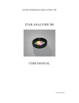
AM-SSBTRANSCEIVER WASHINGTON
@ 355 ,:rJ MO'N(6)NAM~rC(Q)'9. N9)'9.:
The P400 operates on 40 AMchannels, 40 Upper Side Band channels and 40 Lower
Side Band channels.
When transmitting
on SSB, there is no carrier and only one sideband
is on the air either
upper or lower. Your receiver can hear this sideband signal but can't change it into usable information in the AM mode. You can recognize a side band signal being received in
the AM mode by its fluttering unintelligible sound. A signal transmitted on upper sideband can only be properly received with the mode selector of your transceiver in the upper side band position.
When you receive the SSB signal in the proper mode, audio sound may be either too high
pitched, or Iow pitched, indicating that your receiver may not be tuned to the exact same
frequency as the transmitter it is listening to. The P400 is equipped with a Clarifier. By
tuning the Clarifier, you can slightly change the frequency of the receiver. So, you can
get a normal tone.
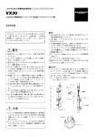
OPERATINGCONTROLS
Your P400 designed for ease of operation, is provided with the following operating controls:
1. ON/OFF VOLUME CONTROL: To turn the transceiver on, rotate the control clockwise past click. To turn the transceiver off, rotate the control counterclockwise past
click. Rotate the control for a comfortable audio level.
2. CHANNEL SELECTOR: This switch is used to select anyone of the 40 Citizens Band
channels. Channel 9 has been reserved by the D.O.C. for emergency communications involving the immediate sa,fety of)ife of individuals or immediate protection of
property. Channel 9 may also be used to render assistance to a motorist.
3. CHANNEL 9 SWITCH: This switch is for use when emergency communications is
needed on the emergency channel, CH9. Pressing the CH9 switch activates CH9 regardless of the position of the channel selector switch. When CH9 switch is pressed,
the channel display is blanked and the CH9 indicator is activated.
~
-
r
/
~-..
;;:;;-""'~"""""_.'
..
,_.
. '>._'
'"
'"
..
'H',
.-
'--
.
H.
-=
. - _..W'
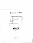
Operating Instructions
4. MODESELECTOR:This switch selects AM, usa, or LSB mode of operation. This
selector changes the mode of operation of both transmitter and receiver simultaneously. Set the selector to the mode on which you desire to communicate.
5. SQUELCH: The squelch control is normally set to a position which eliminates undesired background noise with no signal present. With the audio adjusted to a satisfactory level, rotate the Squelch control clockwise to the point where the sound from the
speaker is cut off. In this position, there will be no sound from the speaker until a signal is received. In order to hear weak signals, it may be necessary to rotate the
Squelch control counterclockwise, allowing some background noise to be heard.
6. PA (Public Address) SWITCH: To engage the PA function, rotate the SQUELCH
control counterclockwise past click. Press the press-tol-talk switch on the microphone and speak in the microphone in a normal voice level. The PA function should
not be used unless the PA speaker is connected.
7. MIKE GAIN: This control is used to adjust, as required, microphone input sensitivity
for the optimum amount of modulation in transmit.
8. RF GAIN: This control is used primarily to optimize reception in strong signal areas.
Gain is reduced by counterclockwise rotation of the control.
9. CLARIFIER:The clarifier is normally set to the center position. This feature has
several uses and can greatly enhance receiver operation. If a received signal is
slightly off frequency, this control can be operated to optimize the received signal.
This control is primarily intended to tune in SSB signals, but it may also be used to
optimize the AM signal.
10. NBI ANL SWITCH: When the switch is placed in the NBI ANL position, the RF Noise
Blanker and Automatic Noise Limiter circuits are activated. The Noise Blanker and
Automatic Noise Limiter circuits are activated. The Noise Blanker cut out annoying
impulse-type noise such as ignition noise on both AM and SSB modes. The Automatic Noise Limiter reduces has-type noise.
INDICATOR FUNCTION
1. S/RF PWR METER: When the transceiver is in the receive mode, relative signal
strength is indicted in S units on the lower scale of the meter. When transmitting, relative power output is indicated on the upper scale of the meter. When the MOD-SI
RF switch is depressed, the meter indicates modulation percentage.
2. TXlRX INDICATOR: This indicator lights in red when the transmitter is in operation
and lights in green when receiver is in operation.
.
3. MODE INDICATOR: This radio is equipped with mode indicator lights for AM, usa
and LSBmodes. When you set the mode selectorto the mode desired, the related indicator light comes on.
4. CH9 INDICATOR:
This indicator lights when the CH9 switch is depressed.
~
.- --
- - - -- -
."«
-
I~
-===
-.
PRESS TO TALK MICROPHONE
The receiver and transmitter are controlled by the press-to-talk switch on the microphone. Pressthe switch and the transmitter is activated. Release the switch to receive.
When transmitting, hold the microphone about three inches from your mouth and speak
clearly in a normal voice.
HEADPHONE
This radio is provided with a headphone jack for private listening. To use this feature, just
plug the headphone plug into the jack labeled "PHONE" on the front pane!
RECEIVE OPERATING
PROCEDURE
1. Turn the SQUELCH control clockwise until click is heard, do not advance too far or
you will not hear any background noise. Advance the RF GAIN control fully clockwise.
2. Turn the set on by turning the VOLUME CONTROL clockwise, past click.
NOTE: Microphone
must be plugged in for the receiver to operate.
3. Set the VOLUME CONTROL to a comfortable level.
4. Set the Mode Selector Switch to the desired mode.
5. Listen to the background noise from the speaker. Turn the SQUELCH CONTROL
slow clockwise, until the noise just disappears. The Squelch is now properly adjt:Jsted. The receiver will remain quiet until a signal is received. Do not advance the control too far, or some of the weaker signals will not be heard.
6. Set the Channel Selector to the desired channel.
7. Adjust the CLARIFIER to clearly receive SSB or AM signals.
TRANSMIT OPERATING
PROCEDURE
1. Select the desired channel of transmission.
2. If the channel is clear, depress the push-to-talk switch on the microphone and speak
into the front of the microphone in a normal voice.
{
---
-.---
--
Specifications
Channels
Frequency Range
Frequency Control
Frequency Tolerance
Frequency Stability
Operating Temperature
Microphone
Input Voltage
40 AM, 40 LSB, 40 USB
26,965 to 27,405 MHz
Phase Locked Loop (PLL) Synthesized
0.0005% Typical
0.001 %
Range -20°C to +50°C
Plug-in type; dynamic with push-to-talk
coiled cord
117V AC nominal.
Cross Modulation
Circuitry.
switch and
13.8V DC nominal. (positive or negative ground)
(120V AC) Transmit: full mod., 75 watts.
Receive: squelched, 45 watts.
Current Drain (13.8V DC)
Transmit: 2.2A typical; 3A maximum.
Receive: squelched, 0.3A; full audio output, 1A
Size
5"H X 131/2"W X 12"D
Weight
13.3 pounds.
Antenna Connector
UHF, SO-239
Meters
Shows relative power output and received signal
strength and modulation.
Semiconductors
46 transistors, 1 field effect transistor, 6 integrated
circuits, 61 diodes and 6 light emitting diodes.
Power Consumption
Modulation
Intermodulation
Distortion
SSB Carrier Suppression
Unwantend Sideband
Frequency Response
Output Impedance
SSB Filter
Output Indicator
AM, 4 watts
SSB, 12 watts, P.E.P.
AM, high and Iow level Class B.
SSB: 3rd and 5th order, more than -25 dB.
7th and 9th oder, more than -35 dB.
More than -45 dB
More than -45 dB
AM and SSB: 300 to 3000 Hz.
.52 ohms, unbalanced
7.8 MHz, crystal lattice type
6 dB ~ 4.2 KHz
60 dB @ 7.0 KHz
Meter shows relative RF output power.
RECEIVER
Sensitivity
Selectivity
Squelch
Noise Blanker
Clarifier Range
Audio Output Power
Frequency Response
Distortion
Built-in Speaker
External Speaker (Not Suppli8 ohms, disables internal speaker when connected.
ed)
PA SYSTEM
Power Output
External Speaker for PA
4.0 watts into External Speaker
8 ohms (not supplied)
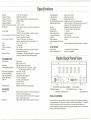
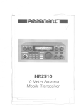
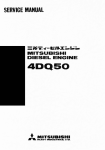
Radio Back Panel View
TRANSMITIER
Power Output
Image Rejection
I.F. Frequency
AM and SSB RF Gain Control
Automatic Gain Control
Better than -5e dB
Better than -60 dB
AM and SSB: 7.8 MHz
Adjustable for optimum signal reception
(AGC): Less than 10 dB change in audio output for
inputs from 10 to 5000.000 microvolts.
Adjustable;.threshold
less than .5IAV
RF type, effective on AM and SSB.
:t 1.25 KHz
4 watts into 8 ohms
300 to 2500 Hz
Less than 10% at 3 watts output.
8 ohms
SSB: Less thanO.25/-lV for 10 dB (S+N)/N at greater than 1/2watt of audio output.
AM: Less than 0.5/-lVfor 10 dB (S+N)/N at greater
than 1/2watt of audio output.
SSB and AM: 6 dB @ 4.2 KHz, 60 dB @ 7.9 KHz
~
@
~~~~
~~~~
~~~~
~~~~
~~~~
~~~~
0
~
13.8V ~c
SERIAL
NO
0 0 o".~
DC
AC
FUSE 120V,AC 60Hz
IDJI[]
El»
,
PA SPEAKER Jack SERIAL NUMBER
I AC/DC Switch
ANTENNA Connector
DC POWER Cord Jack
FUSE
I
EXTERNAL SPEAKER Jack
AC POWER Cord
PUBLIC ADDRESS
An external 8 Ohm, 4 watt speaker may be connected to the PA speaker jack located on
the rear panel when the transceiver is used as a public address system. The speaker
should be directed away from the microphone to prevent acoustic feed-back.
Physical separation or isolation of the microphone and speaker must be used when operating the PA at high output levels:
I~
REMOTE SPEAKER
The external speaker jack (EXT.SPKR.) on the rear panel is used for remote receiver
monitoring.The externalspeaker should have 8 Ohms impedance and be able to handle
at least 4 watts.
Channel Freguencies
Channel
Channel Frequency
Channel
Channel Frequency
1
2
3
4
5
6
7
8
9
10
11
12
13
14
15
16
17
18
19
20
26.965
26.975
26.985
27.005
27.015
26.025
27.035
27.055
27.065
27.075
27.085
27.1 05
27.11 5
27.125
27.135
27.155
27.165
27.175
27.1 85
27.205
21
22
23
24
25
26
27
28
29
30
31
32
33
34
35
36
37
38
39
40
27.215
27.225
27.255
27.235
27.245
27.265
in MHz
in MHz
.
27.275
27.285
27.295
27.305
27.315
27.325
27.335
27.345
27.355
27.365
27.375
27.385
27.395
27.405
NOTE:This radio has been designed to operate in the 11 meter Citizens Radio Service.
It uses a frequency synthesizing crrcuit with Phase Locked Loop (PLL) techniques to
provide crystal controlled transmit and receive operation on all 40 channels.
The PLL circuitry assures ultraprecise frequency control. Itis designed to meet the Department of Communication requirements applicable to equipment operating in the Citizens Band Radio Service, and is not to be used for any other purpose.
r
--.-----.
_.-- -
'-..
Installation
LOCATION
Prior to Deginning operation ofthe transceiver, a basIc installation must De prepared.
stallation of the transceiver itself is a rather simple procedure.
In-
"
In selecting the location for the unit, two factors must be considered:
Z4o
1. Access to a 117' I AC, 60 Hz power source for your BASE STATION installation. Be
sure to connectthe AC power cord to an AC power source, notto a DC Dower source.
2. The location must be convenient for running the antenna lead-in cable to your transceiver.
BASE STATIONANTENNA
Since the maximum allowable power output of the transmitter is limited by the D.O.C.,
the antenna is the most important factor affecting transmission distance. Only a properly matched antenna system will allow maximum power transfer from the 52 Ohm transmission line to the radiating element.
The recommended method of antenna tuning is to use an in-line watt-meter or VS-WS
bridge to adjust the antenna for minimum reflected power on channel 19.
The radio may be used with any type of 52 Ohm base station antenna. A ground plane
vertical antenna will provide the most uniform horizontal coverage. This type of antenna
is best suited for communication with a mobile unit. For point-to-point operation where
both stations are fixed, a directional beam will usually increase communicating range
since this type of antenna concentrates transmitted energy in one direction. The beam
antenna also allows the receiver to "listen" in only one direction thus reducing interfering
signals.
Antenna height is an importantfactorwhen
maximum range is desired. Keep the antenna clear of surrounding structures of foliage. D.O.C. regulations limit antenna height to
20 feet above an existing structure.
MOBILE OPERATION/EMERGENCV POWER OPERATION
It is possible to operate the P400 from an external 13.8V DC power supply for emergency
power conditions or from an automobile battery for mobile operation. The P400 is supplied with a polarized plug for operation with an external DC supply.
Negatiye lead is black.
Positve lead is red and has the in-line fuse holder as an integral part of the positive lead.
....
-.....
-
r
~
--- --- - -
::::=:
't
~
~
Warranty
WARRANTOR:
Uniden Australia Pty. Ltd. ("UNIDEN").
ELEMENTS OF WARRANTY: Uniden warrants, for the duration of this warranty, President P400 CB Radio (hereinafter referred to as the Product) to be free from defects in
materials and craftsmanship with only the limitations or exclusions set out below.
Warranty Duration: This warranty shall' terminate and be of no further effect one (1 )year
after the date of the original purchase of the Product or at the time the Product is (A) damaged or not maintained as reasonable and necessary, (B) modified, (C) improperly installed, (D) repaired by someone other than warrantor for a defect or malfunction
covered by this warranty, (E) used in a manner or purpose for which the Product was not
intended, or (F) sold by the original purchaser.
STATEMENT OF REMEDY: In the event that the Product does not conform to this warranty at any time while this warranty is in effect, warrantor will repairthe defect and return
it to you without charge for parts, service, or any other cost incurred by warrantor or its
representatives in connection with the performance of this warranty. THIS WARRANTY
DOES NOT COVER OR PROVIDE FOR THE REIMBURSEMENT OF PAYMENT OF INCIDENT AL OR CONSEQUENTIAL DAMAGES. Some states do not allow this exclusion
or limitation of incidental or consequential damages, so the above limitation or exclusion
may not apply to you.
PROCEDURE FOR OBTAINING PERFORMANCE OF WARRANTY: In the event that
the Product does not conform to this warranty, the Product should be shipped or delivered, freight prepaid, to warrantor at Uniden Australia Pty. Ltd. 345 Princes Highway,
Rockdale, N.S.W. 2216 with evidence of original purchase.
LEGAL REMEDIES: This warranty gives you specific legal rights, and you may also
have other rights which vary from state to state.
...
~
- -- _.
~
r
b
I<: -
-
-=
,
.""
unidl!n@
Australia Pty. Ltd.
HEAD OFFICE:
345 Princes
Highway,
Phone:
Rockdale,
599 3355
N.S.w.
2216
Fax: (02) 599 7657
BRISBANE
3/12 Randall Street,
Slacks Creek,
Old. 4127
PERTH
23 Geddes Street,
Balcatta,
WA 6021
Phone (07) 290-1188
Phone (09) 344 3937
Fax (09) 349 8165
ADELAIDE
Fax (07) 808 4251
.
,
MELBOURNE & TASMANIA
446-448 Bell Street,
East Preston,
VIC. 3072
Phone (03) 484 0373
Fax (03) 484 6057
UTUA01509GZ
72-74
Halifax Street,
Adelaide
SA 5000
Phone (08) 223-4235
Fax (08) 223 1471
Printed
~
-
in the Philippines
~