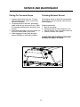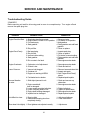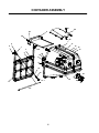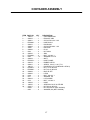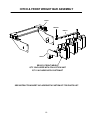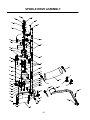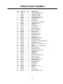
1
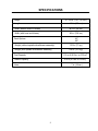
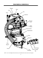
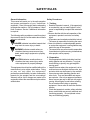
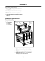
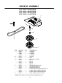
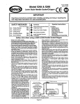
Z9 Commercial
Collection System
Operator and Parts Manual
Models: Z9A
Please read these instructions carefully and make
sure you understand them before using the machine.
Manual No. 200897 Rev. 02 (10-30-03)
INDEX
Operators Guide
Specifications .............................................................................................. 3
Features and Controls ................................................................................. 4
General Information ..................................................................................... 5
Safety Procedures ....................................................................................... 5
Unpacking Instructions ................................................................................ 7
Assembly Instructions ................................................................................. 7
Frame Assembly .................................................................................... 7
Mounting the Z9 ..................................................................................... 8
Spindle Drive and Drive Kit Assembly .................................................... 9
Hose Trimming ..................................................................................... 10
Door Tightness Adjustment .................................................................. 10
Maintenance and Service Instructions
Transport ....................................................................................................11
Cleaning and Washing ...............................................................................11
Storage .......................................................................................................11
Preventative Maintenance Schedule ..........................................................11
Caring for Vacuum Hoses .......................................................................... 12
Cleaning Exhaust Screen ......................................................................... 12
Troubleshooting Guide .............................................................................. 13
Replacement Parts
Container Assembly ................................................................................... 14
Frame Assembly ........................................................................................ 15
Hitch & Front Weight Bar Assembly .......................................................... 16
Spindle Drive Assembly ............................................................................. 17
Drive Kit Assembly ..................................................................................... 19
WARNING: Engine exhaust, some of its constituents, and certain vehicle components contain or emit chemicals known to the State of California to cause cancer and birth defects or
other reproductive harm.
©2003 Yazoo/Kees Power Equipment. All rights reserved.
Beatrice, NE. Printed U.S.A.
2
SPECIFICATIONS
Height
47 - 50 in. (119 - 127 cm.)
Length
38 in. (97 cm.)
Width (without hose or blower)
34.5 in. (94 cm.)
Width (with hose and blower)
49 in. (124 cm.)
Deck Options
42”
48”
Weight (without spindle drive/blower assembly)
170 lb. (77 kg.)
Weight (with spindle drive/blower assembly)
235 lb. (107 kg.)
Total Capacity
11.5 cu ft (9.2 bu. or 0.33 m3)
Usable Capacity
8 cu ft (6.4 bu. or 0.23m3)
Hose
7 in. (18 cm.)
3
FEATURES & CONTROLS
Exhaust
Hood
Inlet
Arm
Door
Container
Release
Lever
Upper
Frame
Lower Frame
Hitch Bracket
Hitch
Drive Kit
Hose
Support
Front Weight
Hose
Fan
Assembly
Front Weight
Bar
NOTE: Your Front Weight Bar and Hitch may look different from those shown in this diagram.
4
SAFETY RULES
Safety Procedures
General Information
This manual will assist you in the safe operation
and proper maintenance of your Yazoo/Kees 1 - Training:
equipment. Read it thoroughly before attempting • Read the Operator’s manual. If the operator(s)
or mechanic(s) can not read English it is the
to operate the machine. Call your dealer or Yazoo/
owner’s responsibility to explain this material to
Kees Customer Service if additional information
them.
is required.
• Become familiar with the safe operation of the
equipment, operator’s controls, and safety
The following safety symbols are used throughout
signs.
the manual to alert you to information about unsafe
• All operators and mechanics should be trained.
actions or situations:
The owner is responsible for training the users.
•
Never
let children or untrained people operate
DANGER indicates immediate hazards that
or
service
the equipment. Local regulations may
may result in severe injury or death.
restrict the age of the operator.
•
The owner/user can prevent and is responsible
WARNING indicates unsafe actions or
for accidents or injuries occurring to themselves,
situations that may cause severe injury,
other people, and/or property.
death, and/or major equipment or property
damage.
2 - Preparation:
• Wear appropriate clothing including hard hat,
CAUTION indicates unsafe actions or
safety glasses and ear protection. Long hair,
situations that may cause injury and/or
loose clothing or jewelry may get tangled in
minor equipment or property damage.
moving parts.
This equipment should not be modified without the • Inspect the area where the equipment is to be
used and remove all objects such as rocks, toys
manufacturer’s prior written authorization. Doing
and wire which can be thrown by the machine.
so may not only affect the equipments’
performance and durability, but also create safety • Use extra care when handling gasoline and
other fuels. They are flammable and vapors
hazards for the operator and the surroundings.
are explosive. Use only an approved container.
Warranty will be void if changes are made to the
Never remove gas cap or add fuel with engine
equipment without the manufacturer’s prior written
running. Allow engine to cool before refueling.
authorization.
Do not smoke while fueling or operating
equipment. Never refuel or drain the machine
indoors.
• Check that operator’s controls, safety switches,
hoses, and shields are securely attached and
functioning properly. Do not operate unless
they are functioning properly.
5
SAFETY RULES
3 - Operation
• Never run an engine in an enclosed area.
• Only operate in good light, keeping away from
holes and hidden hazards.
• Slow down and use extra care on hillsides.
Make turns gradually and at slow speed. Do
not operate across the sides of slopes. Operate
up and down slopes only. Do not operate on
steep slopes.
• Turf conditions can affect the machine’s stability.
Do not operate on wet grass where traction may
be reduced.
• Do not change the engine governor setting or
overspeed the engine.
• Stop equipment and inspect vacuum impellar
and hoses after striking objects or if an abnormal
vibration occurs. Make necessary repairs before
resuming operations.
• Look behind and down before backing up to
ensure a clear path.
• Slow down and use caution when making turns
and crossing roads and sidewalks. Stop vacuum
and mower blades if not mowing.
• Do not operate machine under the influence of
alcohol or drugs.
• Use care when loading or unloading the machine
into a trailer or truck.
• Use care when approaching blind corners,
shrubs, trees, or other objects that may obscure
vision.
4 - Maintenance and Storage:
• Stop engine and disconnect spark plug wire.
Wait for all movement to stop before adjusting,
cleaning, or repairing.
• Clean grass and debris from muffler and engine
to help prevent fires. Clean up oil or fuel sillage.
• Let engine cool before storing and do not store
near flame.
• Shut off fuel while storing. Do not store fuel
near flames or drain indoors.
• Never allow untrained personnel to service
machine.
• Keep hands and feet away from moving parts.
If possible, do not make adjustments with the
engine running.
• Keep all parts in good working condition and all
hardware tightened. Replace all worn or
damaged decals.
6
ASSEMBLY
Unpacking Instructions
1. Wear gloves and eye protection. Remove
wood pieces.
2. Cut straps around carton and remove top.
NOTE: Watch for nails and wood splinters.
3. Slide carton sleeve out of bottom tray and lift
over Z9.
Assembly Instructions
Frame Assembly
Tools Required:
1. 3/4" wrench
2. Ratchet
3. 3/4" socket
Lower
Frame
Upper
Frame
1. Position the Lower Frame inside the Upper
Frame.
2. Align holes corresponding to desired position
of frame.
3. Secure with eight (8) 1/2” x 1-1/4” hex bolts
and eight (8) 1/2” nylon lock nuts.
7
ASSEMBLY
Mounting the Z9
NOTE: This portion of the assembly requires
lifting the Z9; two people are required.
Tools Required:
1. 9/16" wrench
2. Ratchet
3. 9/16" socket
Upper
Frame
Hitch
Hitch
Bracket
Lower
Frame
Wire Lock
Pin
1. Install the Hitch from the Custom Kit according to the instruction sheet included in that
carton.
2. Slide the Z9 into the hitch.
3. Line up holes in the Hitch and Z9 and secure with two (2) 3/8” wire lock pins.
4. Position the Hitch Brackets so that they are
aligned with the holes on the top plate of the
Hitch and the holes in the forward cross bar
of the Lower Frame.
5. Secure with four (4) 3/8” x 1-1/4” hex bolts,
four (4) 3/8” nylon lock nuts, and eight (8) 3/
8” flat washers.
8
ASSEMBLY
Spindle Drive &
Drive Kit Assembly
For use on mowers equipped with either a
42", 48", 52" or 61" deck:
12. Rest the fan assembly onto the deck end and
slide the pilot thru the 5/8” hole previously
mentioned so that fan assembly is supported
by the pilot and the ¼” stop block welded under
1. Remove the discharge chute.
the clamp at the front of the fan assembly.
2. Remove the right hand belt shield.
Note: It may be necessary to swing the
3. Remove the deck belt from the right spindle
idler pulley away from the assembly
assembly sheave.
mounting face to clear the chute mounting
4. Remove this sheave but keep the ¼” square
bar and the discharge chute mounting tab
key and the two washers at hand for reinstalon the deck.
lation.
13. Reinstall the clamp at the front of the assembly
5. Install the Stepped Sheave and spacer/key
so that the tab at the lower end of the clamp
retainer included in the kit using the original
passes thru the rectangular slot at the right
key and washers but substituting the original
front corner of the mower deck, but leave the
7/16” HCS with the longer version provided.
fastener loose to ease belt installation.
An application of anti-seize is recommended. 14. Rotate the belt idler as far forward as possible
6. Reinstall the deck belt.
and install the belt over the top groove of the
7. The 5/8” hole toward the rear of the ¼” thick
new deck sheave.
discharge chute mounting bar at the right end 15. Tighten the clamp fastener.
of the deck may be distorted from forming or 16. Using a scribe or other small sharp object,
loaded with paint. Drill out or fill this hole until
transfer the mounting hole location at the rear
it will accept a 5/8” bolt or piece of bar stock.
edge of the fan assembly onto the mating
Keep the fit close.
vertical surface at the right rear of the mower
8. If any weld beads or the edge of the deck top
deck and drill thru with a 25/64” drill.
project past the right end surface of the deck, 17. Install the stops on the deck stop pins located
these must be ground back to allow the fan
at the rear of the deck then install the new belt
assembly to fit up flush to the end of the deck.
shield.
9. Remove the 3/8” fastener, nut, and clamp from 18. Install the tube support to the main collection
the inside front corner of the fan assembly.
assembly using the 3/8” fastener provided, po10. Remove the sheave floor to expose the fan
sitioning so that the tube is 2” to 3” away from
assembly belt sheave from below.
the tire.
11. Loosen the nut retaining the belt guide/retainer, 19. Install the 7” hose to the fan assembly and the
install the belt from the Drive Kit, retighten the
container input port using the hose clamps
nut, verify the belt clears the guide, and
provided.
reinstall the sheave floor.
20. Clamp the tube to the tube support.
9
ASSEMBLY
Hose Trimming
Tools Required: Utility Knife
3
1. Carefully measure the length needed. Remember that although the hose is flexible, it
will not stretch.
2. Measure the same length on the hose that
needs to be trimmed, and with the utility
knife, cut through the webbing at the proper
location.
Continue that cut through the webbing all the
way around the hose so that it finishes just
across the support coil from where the
original cut was started.
4. Use the utility knife to score the support coil
between the beginning and end of the web
cut. Set aside the knife, and finish breaking
the coil by hand by working the scored
portion back and forth until it breaks apart.
Door Tightness Adjustment
Tools Required:
1. 9/16" Wrench
2. Ratchet
3. 9/16" Socket
4. Clamps
Clevis Pin
Rod
End
Arm
Door
1. Remove arms from door by removing the
3/8” x 1-3/4” clevis pins.
2. Clamp door tightly shut.
3. Adjust arm length so that rod ends on arms
can be fastened to the door.
4. Fasten arms to door.
5. If door is still too tight or too loose, repeat
steps 1-4 and adjust the clamp tightness
until door is at desired tightness.
10
OPERATION
Operating the Vacuum
1. NEVER USE THE Z9 WITHOUT ALL
HOSES AND SHIELDS SECURELY ATTACHED.
2. Make sure all hoses are connected at both
ends. Inspect hoses prior to each use.
3. Do not use the Z9 on slopes greater than 15
degrees.
4. The mower must be running in order to
vacuum debris through the mower deck.
5. In heavy grass it may be necessary to mow
and vacuum at a slower ground speed.
6. Never attempt to unclog the Z9 until both the
mower’s engine and vacuum’s engine
have been shut off and all moving parts have
come to a complete stop.
7. Do not stand behind the vent at the rear of
the Z9 due to the potential for small
pieces of blowing debris to escape through
this vent.
8. Wear eye and ear protection.
11
SERVICE AND MAINTENANCE
Transport
WARNING
The Z1-9 container must be completely
empty while driving forward onto a trailer.
If the Z1-9 must be loaded onto a trailer
while there is still debris in the container,
the mower must be backed up onto the
trailer to avoid tipping.
For best results, clean exhaust screen inside
container regularly. Instructions for doing this
can be found in the Service section of this
manual.
Storage
Cleaning and Washing
1. Refer to engine manufacturer’s instructions
for engine storage information.
2. Clean machine.
3. Cover all scratches with touch-up paint.
4. Covered or indoor storage is recommended.
Regular cleaning, washing, and lubricating will
prolong the service of the machine.
NOTE: Use care with power washers to avoid
damage to decals. Limit direct spray on these
items.
DO NOT EXCEED 1000 PSI WATER PRESSURE FOR CLEANING.
Preventative Maintenance Schedule
Item
Check Engine Oil Level
Before
Each Use
Every
5 Hours
X
Every
25 Hours
Every
50 Hours
X
Change Engine Oil
X
Change Air Cleaner Element
X
Replace Spark Plug
X
Inspect/Clean Exhaust Screen
X
Check/Tighten Nuts & Bolts
X
Check/Tighten Hoses
X
X
Turn Hose End to End
X
Rotate Hose
X
Clean Machine
X
12
SERVICE AND MAINTENANCE
Caring For Vacuum Hoses
Cleaning Exhaust Screen
1. Inspect hoses before each use. If hoses
have excessive wear, tears, or punctures,
replace immediately.
2. To prolong the life of the hose, periodically
rotate hose and turn hose end to end. Refer
to Preventative Maintenance Schedule in this
manual.
3. Avoid twists and sharp turns in the hoses, as
they will increase wear on the hoses.
4. Avoid dragging the lower hose along the
sides of buildings or other hard surfaces.
The exhaust screen on the Z9 is located inside
the container. For best results, clean exhaust
screen regularty.
Cleaning Instructions
1. Shut off all engines.
2. Release the two (2) rubber latches on the
sides of the filter cover, and slide screen out.
3. Clean the screen, and replace.
DO NOT USE THE Z9 WITHOUT EXHAUST
SCREEN SECURELY IN PLACE.
13
SERVICE AND MAINTENANCE
Troubleshooting Guide
! DANGER !
Before servicing unit wait for all moving parts to come to a complete stop. Turn engine off and
remove the spark plug wire.
PROBLEM
POSSIBLE CAUSE
CORRECTION
Engine Does Not Start. 1. Spark plug wire disconnected.
2. Engine ON/OFF switch in OFF position.
3. Fuel tank empty.
4. Stale gasoline.
5. Dirty air filter.
Engine Runs Poorly.
1. Bad spark plug.
2. Dirty air filter.
3. Incorrect choke setting.
4. Stale gasoline.
1. Reconnect wire.
2. Put switch in ON position.
3. Add gasoline.
4. Drain gasoline and add fresh
gasoline.
5. Clean or replace.
5. Dirt or water in fuel tank.
1. Inspect spark plug.
2. Clean or replace.
3. Put choke in correct setting.
4. Drain gasoline and add fresh
gasoline.
5. See engine service dealer.
Engine Overheats.
1. Carburetor out of adjustment.
2. Oil level is low.
1. See engine service dealer.
2. Check and add oil.
Loss of Vacuum.
1. Vacuum inlet clogged.
2. Container full.
3. Engine not reaching full RPM.
1. Remove hose and clean inlet.
2. Inspect and empty.
3. See “Engine Runs Poorly”
above.
4. Replace/repair impeller.
4. Fan blades bent or broken.
Unusual vibration
or noise.
1. Solid object jammed in unit.
2. Engine crankshaft
bent or damaged.
3. Loose engine mounting bolts/nuts.
4. Loose or missing bolts on unit.
5. Engine shaft bearings damaged.
6. Impeller bent or damaged.
Unit difficult to close.
1. Door too tight.
2. Obstructions keeping door from
completely closing.
Door doesn’t shut tightly. 1. Door tightness not adjusted correctly.
14
1. Check and remove any
obstruction.
2. See engine service dealer.
3. Tighten bolts/nuts.
4. Tighten or replace bolts.
5. See engine service dealer.
6. Repair/replace impeller.
1. Adjust arm tightness
2. Clear obstructions.
1. Adjust arms.
PARTS ILLUSTRATION
15
CONTAINER ASSEMBLY
27
26
2
24
16
28
1
11
4
6
7
8
3
12 18
13
15
4
12
17
25
8
17
10
9
23
14
7
5
17
16
19
20
21
22
CONTAINER ASSEMBLY
ITEM PART NO.
QTY
DESCRIPTION
1 ........ 108970 ............ 1 ........ CONTAINER ASM.
2 ........ 200876 ............ 1 ........ EXHAUST ASM.
3 ........ 200691 ............ 2 ........ CLEVIS PIN 1/4 X 2 3/4
4 ........ ER99082 ......... 4 ........ HAIR PIN #13
5 ........ 200875 ............ 1 ........ DOOR ASM.
6 ........ 200692 ............ 2 ........ CLEVIS PIN 3/8 X 1 3/4
7 ........ 30425 ............. 4 ........ ROD END
8 ........ 200690 ............ 4 ........ PLUG
9 ........ 0224 ............... 2 ........ NUT 3/8-24
10 ....... 200520 ............ 2 ........ ARM
11 ....... ER99008 ......... 6 ........ BOLT, 1/4-28 X 1
12 ....... 0405 ............... 12 ....... WASHER 1/4 FLAT
13 ....... 200408 ............ 1 ........ INLET
14 ....... ER97076 ......... 1 ........ HOSE CLAMP
15 ....... 200478 ............ 2 ........ RUBBER LATCH
16 ....... 200641 ............ 6 ........ SCREW, 10-24 X 1 1/4, P.T.H.
17 ....... 108134 ............ 1 ........ DOOR SEAL KIT, (CONTAINS 3 SEALS)
18 ....... ER99072 ......... 6 ........ NUT, 1/4-20, NYLOC
19 ....... ER99065 ......... 4 ........ NUT, 3/8-16, NYLOC
20 ....... 200688 ............ 1 ........ BACK PLATE
21 ....... 200695 ............ 1 ........ LATCH
22 ....... 0168 ............... 4 ........ BOLT, 3/8-16 X 1
23 ....... 0417 ............... 2 ........ WASHER, 3/8
24 ....... 200423 ............ 2 ........ LATCH BASE
25 ....... 0134 ............... 2 ........ BOLT, 1/4-20 X 2
26 ....... 109399 ............ 1 ........ HOOD
27 ....... 108535 ............ 6 ........ SCREW #10-24 X 3/4 STD RD
28 ....... 976977 ............ 6 ........ NUT #10-24, NYLOC
.......... 02004 ............. 6 ........ NUT #10 NYLOC (NOT SHOWN)
.......... 0403 ............... 6 ........ WASHER, #10 (NOT SHOWN)
17
FRAME ASSEMBLY
19
17
18
16
14
11
15
9
8
2
12
13
11
10
7
3
6
5
4
6
1
20
7
ITEM
1 ........
2 ........
3 ........
4 ........
5 ........
6 ........
7 ........
8 ........
9 ........
10 .......
11 .......
12 ......
13 ......
14 .......
15 .......
16 ......
17 ......
18 ......
19 ......
20 ......
PART NO.
QTY
62072 ............. 1 ........
200510 ........... 1 ........
ER99069 ......... 8 ........
ER99020 ......... 4 ........
ER93082 ......... 8 ........
0415 ............... 8 ........
ER99065 ......... 4 ........
ER99072 ......... 2 ........
0405 ............... 2 ........
0425 ............... 1 ........
03585 ............. 2 ........
200423 ........... 1 ........
200708 ........... 1 ........
ER99008 ......... 2 ........
0382 ............... 1 ........
200710 ........... 1 ........
10195 ............. 2 ........
200712 ........... 1 ........
61481 ............. 1 ........
61532 ............. 2 ........
18
DESCRIPTION
LOWER FRAME
UPPER FRAME
BOLT, 1/2-13 X 1 1/4
BOLT, 3/8-16 X 1 1/4
NUT, 1/2-13, NYLOC
WASHER, 3/8
NUT, 3/8-16, NYLOC
NUT, 1/4-20, NYLOC
WASHER, 1/4
WASHER, 1/2
PIN, COTTER, 3/32 X 3/4
LATCH BASE
LATCH CATCH
BOLT, 1/4-20 X 1
PIN, CLEVIS, 3/16 X 1
LATCH ROD
SPRING
LATCH HANDLE
HANDLE GRIP
HITCH BRACKET
HITCH & FRONT WEIGHT BAR ASSEMBLY
200209
ER99668
ER92731
200810
ER92531 FRONT WEIGHT
QTY 2 INCLUDED WITH COLLECTION UNIT
QTY 1 INCLUDED WITH CUSTOM KIT
SEE INSTRUCTION SHEET INCLUDED WITH CUSTOM KIT FOR PARTS LIST.
19
SPINDLE DRIVE ASSEMBLY
19
5
22
28
21
23
7
1
20
6
27
24
39
2
23
14
27
21
4
10
40
9
46
36
42
37
35
25
11
33
14
18
34
31
32
13
26
30
28
29
44
8
46
45
43
8
12
15
41
17
15
16
27
28
38
29
28
29
3
20
SPINDLE DRIVE ASSEMBLY
ITEM
1 ........
2 ........
3 ........
4 ........
5 ........
6 ........
7 ........
8 ........
9 ........
10 .......
11 .......
12 .......
13 .......
14 .......
15 .......
16 .......
17 .......
18 .......
19 .......
20 .......
21 .......
22 .......
23 .......
24 .......
25 .......
26 .......
27 .......
28 .......
29 .......
30 .......
31 .......
32 .......
33 .......
34 .......
35 .......
36 .......
37 .......
38 .......
39 .......
40 .......
41 .......
42 .......
43 .......
44 .......
45 .......
46 .......
PART NO.
QTY
DESCRIPTION
106752 ............ 1 ........ FAN COVER W/DECALS
108941 ............ 1 ........ UPPER HOUSING
109900 ............ 1 ........ LOWER HOUSING
106786 ............ 2 ........ BEARING W/O COLLAR
106786 ............ 1 ........ LOCKING COLLAR
106707 ............ 1 ........ FAN WLDMT.
102691 ............ 5 ........ FLANGETTE
108944 ............ 2 ........ BLOWER PIN WELDMENT
108301 ............ 1 ........ SHEAVE FLOOR
106713 ............ 1 ........ SHEAVE, 4”
976941 ............ 4 ........ HCS 3/8-16 X 1 1/4
106715 ............ 1 ........ IDLER ARM
101836 ............ 1 ........ SLEEVE BUSHING
990546 ............ 2 ........ NUT 3/8 CTR. LOCK
990629 ............ 2 ........ HCS 3/8 X 2.25
990655 ............ 1 ........ HCS 3/8 X 1.50
990517 ............ 1 ........ WASHER 3/8 FLAT
990122 ............ 1 ........ WASHER 3/8 SAE
102535 ............ 1 ........ GREASE CAP
100472 ............ 3 ........ RHSNB 5/16 X 1.25
990184 ............ 13 ....... NUT 5/16 CTR. LOCK
990717 ............ 3 ........ NUT 5/16 NYLOC
990799 ............ 8 ........ RHSNB 5/16 X .625 SHORT NECK
990208 ........... 1 ........ RHSNB 5/16 X 1.00
990362 ............ 2 ........ SCREW 1/4 X .625 SELF TAP
106721 ............ 1 ........ IDLER
990074 ............ 16 ....... RHSNB 1/4 X .75 SHORT NECK
976978 ............ 16 ....... NUT 1/4 NYLOC
990598 ............ 14 ....... WASHER 1/4 FLAT
990188 ............ 1 ........ WASHER 5/16 FLAT SAE
106801 ............ 1 ........ SPRING ROD
106720 ............ 1 ........ SPRING
101050 ............ 1 ........ VINYL GRIP
990037 ............ 1 ........ COTTER PIN 3/32 X .750
100141 ............ 1 ........ HCS 7/16F X 1.5
106504 ............ 1 ........ HEAVY WASHER
990247 ............ 1 ........ WASHER 7/16 LOCK
976979 ............ 9 ........ NUT 3/8 NYLOC
106809 ............ 1 ........ BEARING PLATE
106811 ............ 1 ........ BELT GUIDE
106812 ............ 1 ........ BACKING
102067 ............ 1 ........ KEY 1/4 X .75 SQ.
106751 ............ 1 ........ SUPPORT
106748 ............ 1 ........ HOSE
097076 ............ 1 ........ HOSE CLAMP
109901 ............ 2 ........ OVER CENTER BAND
21
DRIVE KIT ASSEMBLY
(539) 108960 - 42 INCH DECK
(539) 108961 - 48 INCH DECK
(539) 108962 - 52 INCH DECK
(539) 108963 - 61 INCH DECK
1
8
3
4
2
5
6
7
ITEM
1 ........
..........
..........
..........
2* .......
3 ........
4 ........
5 ........
..........
..........
..........
6 ........
..........
..........
7 ........
..........
..........
8 ........
PART NO.
QTY
108950 ............ 1 ........
108953 ............ 1 ........
108958 ............ 1 ........
108959 ............ 1 ........
106739 ............ 1 ........
976998 ............ 1 ........
108951 ............ 1 ........
106723 ............ 1 ........
106724 ............ 1 ........
106725 ............ 1 ........
106726 ............ 1 ........
106744 ............ 1 ........
106745 ............ 1 ........
106746 ............ 1 ........
108946 ............ 1 ........
108947 ............ 1 ........
108948 ............ 1 ........
106787 ............ 2 ........
DESCRIPTION
42 SHIELD
48 SHIELD
52 SHIELD
61 SHIELD
SPACER
ZERK
HCS 7/16 X 2.5, SPEC.
BELT-42
BELT-48
BELT-52
BELT-61
STACKED SHEAVE 42-48
STACKED SHEAVE 52
STACKED SHEAVE 61
DOUBLE HEX STACKED SHEAVE 42-48
DOUBLE HEX STACKED SHEAVE 52
DOUBLE HEX STACKED SHEAVE 61
STOP - USED ON 42” & 48” ONLY
*NOTE: ITEM 2 USED ON KEYED SHAFT ASSEMBLIES ONLY.
22
23
Yazoo/Kees Power Equipment
700 Park St.
Beatrice, NE 68310
PHONE (402) 223-2391
TOLL FREE PHONE (877) 368-TURF
FAX (402) 223-4791
WEBSITE www.yazookees.com
Technical Assistance:
For technical assistance, please contact your local dealer
or Yazoo/Kees Customer Service.
MANUAL NO. 200897 REV A