1
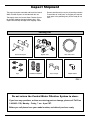
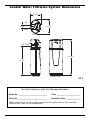
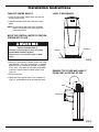
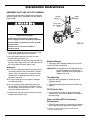
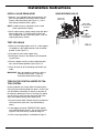
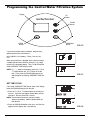
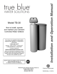
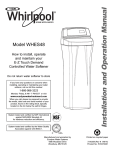
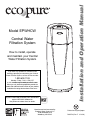
Central Water
Filtration System
How to install, operate
and maintain your Central
Water Filtration System
If you have any questions or concerns when
installing, operating or maintaining your Central
Water Filtration System, call our toll free number:
1-800-693-1138
Monday- Friday, 7 AM - 6 PM CST
or visit www.ecopurewaterproducts.com
When you call, please be prepared to provide the
model, date code and serial number of your product,
located on the rating decal on back of the cover.
Systems tested and certified by NSF International
against NSF/ANSI Standard 42.
See performance data sheet for details.
Manufactured and warranted by
Ecodyne Water Systems LLC
1890 Woodlane Drive
Woodbury, MN 55125
Installation and Operation Manual
Model EPWHCW
Printed on recycled paper
7306774 (Rev. F 1/18/10)
TABLE OF CONTENTS
Central Water Filtration System Safety . . . . . . . . . . . . . . . . . . . . . . . . . . . . . . . . . . . . . . . . . . . . . . . . . . . . . . . . . . .3
Before You Start . . . . . . . . . . . . . . . . . . . . . . . . . . . . . . . . . . . . . . . . . . . . . . . . . . . . . . . . . . . . . . . . . . . . . . . . . . . . 3
Inspect Shipment . . . . . . . . . . . . . . . . . . . . . . . . . . . . . . . . . . . . . . . . . . . . . . . . . . . . . . . . . . . . . . . . . . . . . . . . . . . .4
Central Water Filtration System Dimensions . . . . . . . . . . . . . . . . . . . . . . . . . . . . . . . . . . . . . . . . . . . . . . . . . . . . . . .5
How a Central Water Filtration System Works . . . . . . . . . . . . . . . . . . . . . . . . . . . . . . . . . . . . . . . . . . . . . . . . . . . . . .6
Normal Operation . . . . . . . . . . . . . . . . . . . . . . . . . . . . . . . . . . . . . . . . . . . . . . . . . . . . . . . . . . . . . . . . . . . . . . . . .6
Clean Rinse Cycle . . . . . . . . . . . . . . . . . . . . . . . . . . . . . . . . . . . . . . . . . . . . . . . . . . . . . . . . . . . . . . . . . . . . . . . .6
Applications for a Central Water Filtration System . . . . . . . . . . . . . . . . . . . . . . . . . . . . . . . . . . . . . . . . . . . . . . .6
Installation Requirements . . . . . . . . . . . . . . . . . . . . . . . . . . . . . . . . . . . . . . . . . . . . . . . . . . . . . . . . . . . . . . . . . . . . . 7
Tools Needed . . . . . . . . . . . . . . . . . . . . . . . . . . . . . . . . . . . . . . . . . . . . . . . . . . . . . . . . . . . . . . . . . . . . . . . . . . . .7
Location Requirements . . . . . . . . . . . . . . . . . . . . . . . . . . . . . . . . . . . . . . . . . . . . . . . . . . . . . . . . . . . . . . . . . . . .7
Air Gap requirements . . . . . . . . . . . . . . . . . . . . . . . . . . . . . . . . . . . . . . . . . . . . . . . . . . . . . . . . . . . . . . . . . . . . . .8
Valve Drain Requirements . . . . . . . . . . . . . . . . . . . . . . . . . . . . . . . . . . . . . . . . . . . . . . . . . . . . . . . . . . . . . . . . . .8
Plan the Installation . . . . . . . . . . . . . . . . . . . . . . . . . . . . . . . . . . . . . . . . . . . . . . . . . . . . . . . . . . . . . . . . . . . . . . . . . 9
Inlet - Outlet Plumbing Options . . . . . . . . . . . . . . . . . . . . . . . . . . . . . . . . . . . . . . . . . . . . . . . . . . . . . . . . . . . . . .9
Installation Instructions . . . . . . . . . . . . . . . . . . . . . . . . . . . . . . . . . . . . . . . . . . . . . . . . . . . . . . . . . . . . . . . . . . . . . . 10
Turn Off Water Supply . . . . . . . . . . . . . . . . . . . . . . . . . . . . . . . . . . . . . . . . . . . . . . . . . . . . . . . . . . . . . . . . . . . 10
Move the Central Water Filtration System into Place . . . . . . . . . . . . . . . . . . . . . . . . . . . . . . . . . . . . . . . . . . . . 10
Assemble Inlet & Outlet Plumbing . . . . . . . . . . . . . . . . . . . . . . . . . . . . . . . . . . . . . . . . . . . . . . . . . . . . . . . . . . 11
Install Valve Drain Hose . . . . . . . . . . . . . . . . . . . . . . . . . . . . . . . . . . . . . . . . . . . . . . . . . . . . . . . . . . . . . . . . . . .12
Test for Leaks . . . . . . . . . . . . . . . . . . . . . . . . . . . . . . . . . . . . . . . . . . . . . . . . . . . . . . . . . . . . . . . . . . . . . . . . . .12
Turn On the Central Water Filtration System . . . . . . . . . . . . . . . . . . . . . . . . . . . . . . . . . . . . . . . . . . . . . . . . . .12
Start Up Procedure . . . . . . . . . . . . . . . . . . . . . . . . . . . . . . . . . . . . . . . . . . . . . . . . . . . . . . . . . . . . . . . . . . . . . . . . . .13
Programming the Central Water Filtration System . . . . . . . . . . . . . . . . . . . . . . . . . . . . . . . . . . . . . . . . . . . . . . . . . .14
Set Time of Day . . . . . . . . . . . . . . . . . . . . . . . . . . . . . . . . . . . . . . . . . . . . . . . . . . . . . . . . . . . . . . . . . . . . . . . . .14
Customizing Features / Options . . . . . . . . . . . . . . . . . . . . . . . . . . . . . . . . . . . . . . . . . . . . . . . . . . . . . . . . . . . . . . . .15
Start a Clean Rinse Cycle . . . . . . . . . . . . . . . . . . . . . . . . . . . . . . . . . . . . . . . . . . . . . . . . . . . . . . . . . . . . . . . . .15
Set Number of Days Between Clean Rinse Cycles . . . . . . . . . . . . . . . . . . . . . . . . . . . . . . . . . . . . . . . . . . . . . .15
Set Clean Rinse Time . . . . . . . . . . . . . . . . . . . . . . . . . . . . . . . . . . . . . . . . . . . . . . . . . . . . . . . . . . . . . . . . . . . .15
Set Length of Clean Rinse . . . . . . . . . . . . . . . . . . . . . . . . . . . . . . . . . . . . . . . . . . . . . . . . . . . . . . . . . . . . . . . . .15
Operating in Manual Clean Rinse Mode . . . . . . . . . . . . . . . . . . . . . . . . . . . . . . . . . . . . . . . . . . . . . . . . . . . . . .16
Power Outage Memory . . . . . . . . . . . . . . . . . . . . . . . . . . . . . . . . . . . . . . . . . . . . . . . . . . . . . . . . . . . . . . . . . . .16
Care of Your Central Water Filtration System . . . . . . . . . . . . . . . . . . . . . . . . . . . . . . . . . . . . . . . . . . . . . . . . . . . . .17
Vacations & Extended Periods of No Water Use . . . . . . . . . . . . . . . . . . . . . . . . . . . . . . . . . . . . . . . . . . . . . . . .17
Protect the Central Water Filtration System from Freezing . . . . . . . . . . . . . . . . . . . . . . . . . . . . . . . . . . . . . . . .17
Warranty . . . . . . . . . . . . . . . . . . . . . . . . . . . . . . . . . . . . . . . . . . . . . . . . . . . . . . . . . . . . . . . . . . . . . . . . . . . . . . . . . 18
Troubleshooting . . . . . . . . . . . . . . . . . . . . . . . . . . . . . . . . . . . . . . . . . . . . . . . . . . . . . . . . . . . . . . . . . . . . . . . . . . . . 19
Cleaning the Drain Flow Control . . . . . . . . . . . . . . . . . . . . . . . . . . . . . . . . . . . . . . . . . . . . . . . . . . . . . . . . . . . .20
Cleaning the Sediment Screen . . . . . . . . . . . . . . . . . . . . . . . . . . . . . . . . . . . . . . . . . . . . . . . . . . . . . . . . . . . . .21
Wiring Schematic . . . . . . . . . . . . . . . . . . . . . . . . . . . . . . . . . . . . . . . . . . . . . . . . . . . . . . . . . . . . . . . . . . . . . . . . . . .22
Specifications . . . . . . . . . . . . . . . . . . . . . . . . . . . . . . . . . . . . . . . . . . . . . . . . . . . . . . . . . . . . . . . . . . . . . . . . . . . . . .22
Exploded View & Parts List . . . . . . . . . . . . . . . . . . . . . . . . . . . . . . . . . . . . . . . . . . . . . . . . . . . . . . . . . . . . . . . . . . . 24
Questions?
Visit www.ecopurewaterproducts.com or call Toll Free 1-800-693-1138
Monday - Friday, 7 am - 6 pm CST
2
Central Water Filtration System Safety
Your safety and the safety of others are very important.
We have provided many safety messages in this manual and on your appliance. Always read and obey all safety
messages.
This is the safety alert symbol.
This symbol alerts you to potential hazards that can kill or hurt you and others.
All safety messages will follow the safety alert symbol and either the word “DANGER” or “WARNING”
These words mean:
You can be killed or seriously injured if you don’t
immediately follow instructions.
You can be killed or seriously injured if you don’t
follow instructions.
All safety messages will tell you what the potential hazard is, tell you how to reduce the chance of injury, and tell
you what can happen if the instructions are not followed.
In the state of Massachusetts: The Commonwealth of Massachusetts plumbing code
248-CMR shall be adhered to. A licensed plumber shall be used for this installation.
Before You Start
= See "Installation Requirements" section before installing Central Water Filtration System.
= Before you begin installation, read this entire manual. Then, obtain all the materials and tools you will need to
make the installation. Check local plumbing and electrical codes.
= Use only lead-free solder and flux for all sweat-solder connections, as required by federal codes.
= Use care when handling the Central Water Filtration System. Do not turn upside down, drop, or set on sharp protrusions.
= Avoid installing in direct sunlight. Excessive sun heat may cause distortion or other damage to non-metallic parts.
= The Central Water Filtration System has a maximum allowable inlet water pressure of 125 psi and a minimum of
30 psi. If daytime pressure is over 80 psi, nighttime pressure may exceed the maximum. Use a pressure reducing valve if necessary (Adding a pressure reducing valve may reduce the flow.). If your home is equipped with a
back flow preventer, an expansion tank must be installed in accordance with local codes and laws.
= The Central Water Filtration System works on 24 volt, 60 Hz electrical power only, supplied by a direct plug-in
transformer (included). Be sure to use the included transformer and plug it into a nominal 120V, 60 cycle household outlet that is properly protected by an overcurrent device such as a circuit breaker or fuse. If transformer is
replaced, use only the authorized service, Class II, 24V 10VA transformer.
= Do not use the Central Water Filtration System with water that is microbiologically unsafe or of unknown quality
without adequate disinfection before or after the system.
European Directive 2002/96/EC requires all electrical and electronic equipment to be disposed of according to Waste Electrical and Electronic Equipment (WEEE) requirements. This directive or similar laws
are in place nationally and can vary from region to region. Please refer to your state and local laws for
proper disposal of this equipment.
3
Inspect Shipment
The parts required to assemble and install the Central
Water Filtration System are included with the unit.
Remove and discard (or recycle) all packing materials.
To avoid loss of small parts, we suggest you keep the
small parts in the parts bag until you are ready to use
them.
Thoroughly check the Central Water Filtration System
for possible shipping damage and parts loss. Also
inspect and note any damage to the shipping carton.
Packing List
Ground Clamp Kit
Clips
10 ft. Drain Hose
Bypass Valve
Hose Clamps
Installation Adaptors
Adaptor Elbow
FIG. 1
Do not return the Central Water Filtration System to store.
If you have any questions, or there are missing parts or damage, please call Toll Free
1-800-693-1138, Monday - Friday, 7 am - 6 pm CST.
Before you call please have your model number, and date of purchase ready.
4
Central Water Filtration System Dimensions
10-1/8"
IN
13-7/16"
3-3/8"
OUT
TOP VIEW
IN - OUT
33-3/4"
27-1/2"
SIDE VIEW
FRONT VIEW
FIG. 2
For future reference, enter the following information.
Model No. _____________________________
Code ________________________
Serial No. _____________________________
Installation Date _______________
Model No. and Serial No. are on the shipping carton and on the registration decal on the Central Water
Filtration System. Code is on the registration decal.
5
How a Central Water Filtration System Works
NORMAL OPERATION
APPLICATIONS FOR A CENTRAL WATER
FILTRATION SYSTEM
During normal operation water enters the Central
Water Filtration System and flows through several filtration processes where tastes, odors and sediment
are reduced.
= Do not use the Central Water Filtration System with
water that is microbiologically unsafe or of unknown
quality without adequate disinfection before or after
the system.
= The Central Water Filtration System may not be an
effective treatment method for water sources with a
hydrogen sulfide problem (rotten egg odor or taste)
If your water has hydrogen sulfide, contact a water
treatment expert or call 1-800-693-1138.
CLEAN RINSE CYCLE
A Clean Rinse cycle will automatically be initiated
based on how the controller has been programmed.
The Clean Rinse cycle lifts and expands the media
bed to rejuvenate the media and then repacks the bed
for continued use. During the Clean Rinse cycle, dirt,
sediment, etc. are flushed from the Central Water
Filtration System down the drain.
= The Central Water Filtration System will not remove
iron and is not intended to replace iron treatment
equipment.
= Although the Central Water Filtration System has
sediment filter capabilities, additional sediment filtration may be needed in problem water applications.
6
Installation Requirements
TOOLS NEEDED
LOCATION REQUIREMENTS
Consider the following when selecting an installation
location for the Central Water Filtration System.
Assemble the required tools before starting installation.
Read and follow instructions provided with any tools
listed here.
= Do not operate the Central Water Filtration System
where freezing temperatures occur. Do not attempt
to treat water over 120ºF. Freezing temperatures or
hot water damage voids the warranty.
= Screwdriver
= Tape measure
= Pliers
= To condition all water in the home, install the
Central Water Filtration System close to the water
supply inlet, and before all other plumbing connections, except outside water pipes.
If using Soldered Copper Pipe
= Tubing cutter
= Lead-free solder and flux
= Propane torch
= Emery cloth, sandpaper or steel wool
= Misc. copper pipe fittings
If using CPVC Plastic
= A nearby drain is needed to carry away Clean
Rinse discharge water. Use a floor drain, laundry
tub, sump, standpipe, or other options (check your
local codes). See "Air Gap Requirements" and
"Valve Drain Requirements" sections. If a drain is
not available, it is still possible to operate the
Central Water Filtration System in a manual Clean
Rinse mode. See “Operating in Manual Clean
Rinse Mode.” The automatic Clean Rinse must be
disabled if the Central Water Filtration System will
not be connected to a drain (See Page 8).
If using Other
= Do not install the Central Water Filtration System
on a hot water line (See Figure 3 below).
If using Threaded Pipe
= Pipe cutter or hacksaw
= Pipe joint compound
= Threading tool
= Misc. threaded pipe fittings
= The Central Water Filtration System works on
24 volt, 60 Hz electrical power only, supplied by a
direct plug-in transformer (included). Provide an
electrical outlet in accordance with NEC and local
codes.
= Pipe cutter
= Solvent cement
= Hacksaw
= Primer
= Adjustable wrench
= Other pipe and fittings suitable for potable water as
required by piping system manufacturer and local
codes and/or ordinances.
= Install the Central Water Filtration System between
the home’s incoming water supply and the water
softener, if one is being used (See Figure 3).
THE PROPER ORDER TO INSTALL WATER TREATMENT EQUIPMENT
Untreated Water to
Outside Faucets
Cold Water
to House
Hot Water
to House
City Water Supply
Optional
Sediment
Filter
Water
Heater
Water
Softener
Pressure
Tank
OR
Well Water Supply
Central
Water
Filtration
System
Well
Pump
FIG. 3
7
Installation Requirements
PLUMBING CODES
VALVE DRAIN REQUIREMENTS
All plumbing must be completed in accordance with
national, state and local plumbing codes.
Using the flexible drain hose (included), measure and
cut to the length needed. Flexible drain hose is not
allowed in all localities (check your plumbing codes). If
local codes do not allow use of a flexible drain hose, a
rigid valve drain run must be used. Purchase a compression fitting (1/4 NPT x 1/2 in. minimum tube) and
1/2" tubing from your local hardware store. Plumb a
rigid drain as needed (see Figure 4, below).
In the state of Massachusetts: The Commonwealth
of Massachusetts plumbing code 248-CMR shall
be adhered to. A licensed plumber shall be used
for this installation.
NOTE: Avoid drain hose runs longer that 30 feet.
Make the valve drain line as short and direct
as possible.
AIR GAP REQUIREMENTS
A drain is needed for Clean Rinse discharge water. A
floor drain, close to the Central Water Filtration
System, is preferred. A laundry tub, standpipe, etc.
are other drain options. Secure valve drain hose in
place. Leave an air gap of 1-1/2” between the end of
the hose and the drain. This gap is needed to prevent
backflow of sewer water into the Central Water
Filtration System . Do not put the end of the drain
hose into the drain.
It is recommended that the Central Water Filtration
System be installed near a drain. However, if a drain
is not available, it is still possible to operate the
Central Water Filtration System in.a manual Clean
Rinse mode. See “Operating in Manual Clean Rinse
Mode” section. The automatic Clean Rinse function
must be disabled if the Central Water Filtration System
will not be connected to a drain.
CONNECTING VALVE TO DRAIN
SUBSTITUTING RIGID DRAIN LINE
Drain
Fitting
1/4 NPT Threads
Barbs
Hose
Clamp
1/2” Outside Dia.
Copper Tube
(not included)
Clip
To drain point other
than floor drain.
Support tubing in
place as needed.
Valve
Drain
Hose
Install adaptor
elbow using hose
clamp. Aim nozzle down toward
center of drain
Tie or wire
tubing in
place
Drain grate with 1”
dia. hole in center
Cut barbs from
drain fitting (pull
clip to remove fitting from valve)
Comp Fitting. 1/4
NPT x 1/2” O.D.
Tube (not included)
1-1/2”
air gap
1-1/2”
air gap
LAUNDRY TUB
FLOOR DRAIN
8
1-1/2”
air gap
STANDPIPE
FIG. 4
Plan the Installation
INLET - OUTLET PLUMBING OPTIONS
3 VALVE BYPASS
Install a single bypass valve (provided) to the contractor/plumber-supplied plumbing, as shown in Fig. 7 OR
if desired, a 3 valve bypass system (parts not included) can be installed, as shown in Figure 6. Bypass
valves allow you to turn off water to the Central Water
Filtration System for maintenance if needed, but still
have water in house pipes.
Use either:
= Copper pipe
= Threaded pipe
= PEX (Crosslinked Polyethylene) pipe
= CPVC plastic pipe
= Other pipe approved for use with potable water
Central Water Filtration
System OUTLET
Central Water Filtration
System INLET
IMPORTANT: Do not solder with plumbing attached to
installation adapters and single valve
bypass. Soldering heat will damage the
adapters and valve.
CONNECTING PLUMBING TO VALVE
OUT
IN
1” NPT Sweat
Adapter (2)
(not included)
Use teflon tape,
pipe joint compound or both
CROSS OVER
In what direction does the water flow?
1” NPT
Adapter
Be sure to plan piping so water flow is to the
Central Water Filtration System valve INLET.
Plan a crossover if flow is from left to right.
Main
Wate
r
2 of each
included
Clip
Pipe
Valve
Inlet
Bypass
Valve
OUT
Treated
Water from
Valve
OUTLET
IN
Use teflon tape,
pipe joint compound or both
Untreated
Water to
Valve
INLET
1” NPT
Adapter
To Central Water
Filtration System
FIG. 6
Valve
Inlet
FIG. 5
9
Clip
1” NPT Sweat
Adapter (2)
(not included)
2 of each
included
FIG. 7
Installation Instructions
TURN OFF WATER SUPPLY
LEVEL IF NECESSARY
1. Close the main water supply valve, near the well
pump or water meter.
2. Open all faucets to drain water from the house
pipes.
NOTE: Be sure not to drain water from the water
heater, as damage to the water heater elements could result.
MOVE THE CENTRAL WATER FILTRATION
SYSTEM INTO PLACE
Excessive Weight Hazard
Use two or more people to move and install
Central Water Filtration System.
Plywood
Shim(s)
Failure to do so can result in back or other
injury.
FIG. 8
1. Move the Central Water Filtration System into installation position. Set it on a level surface. If needed,
place the unit on a section of plywood, a minimum
of 5/8” thick. Then place shims under the plywood
to level the Central Water Filtration System (see
Figure 8).
REMOVE TOP COVER AND HANG IT
FROM POST ON FRONT OF RIM
2. Remove top cover.
3. Hang cover from post on front of rim, as shown in
Figure 9. Avoid allowing cover to hang from wires.
Post
Top Cover
FIG. 9
10
Installation Instructions
ASSEMBLE INLET AND OUTLET PLUMBING
A ground clamp should be installed on the household
plumbing supply lines in accordance with the National
Electric Code.
Ground
Clamp (2)
Screw with
lock washer
& nut
Metal
Pipes
Plastic
Bypass
Valve
Electrical Shock Hazard
Install metal ground clamp to metal house
water supply pipe before beginning installation.
Securely tighten connection in center of metal
ground clamp.
FIG. 10
Failure to do so can result in death or
electrical shock.
1. Install metal grounding clamp to metal house water
supply pipes before beginning installation.
2. Securely tighten connection in center of metal
ground clamp (See Figure 10).
Soldered Copper
3. Loosely assemble any pipe and fittings needed from
the main water supply to the inlet and outlet ports of
the Central Water Filtration System valve.
1. Thoroughly clean and apply solder flux to all joints.
2. Make all solder connections.
IMPORTANT:
IMPORTANT: Do not solder with plumbing attached to
installation Adapters and single valve
bypass. Soldering heat will damage the
Adapters and valve.
= Be sure to fit, align and support all plumbing to prevent putting stress on the Central Water Filtration
System valve inlet and outlet. Undue stress from
misaligned or unsupported plumbing may cause
damage to the valve.
Threaded Pipe
1. Apply pipe joint compound or Teflon® tape to all
male pipe threads.
= Be sure to keep fittings fully together, and pipes
squared and straight.
2. Tighten all threaded joints and make all solder connections.
= Be sure incoming water supply pipe goes to the
Central Water Filtration System valve INLET side.
Inlet and outlet are marked on the valve. Trace the
water flow direction to be sure.
CPVC Plastic Pipe
1. Clean, prime and cement all joints, following the
manufacturer's instructions supplied with the plastic
pipe and fittings.
4. Complete the inlet and outlet plumbing for the type
of pipe as described at right:
Other, including PEX (Crosslinked
Polyethylene)
1. Follow the piping system manufacturer's instructions
when using other pipe approved for potable water.
® Teflon is a registered trademark of E.I. Du Pont de
Nemours and Company.
11
Installation Instructions
SINGLE BYPASS VALVE
INSTALL VALVE DRAIN HOSE
1. Measure, cut to needed length and connect the 3/8"
drain line (provided) to the Central Water Filtration
System valve drain fitting (See Figure 11). Use a
hose clamp to hold the hose in place.
Drain Line
Connection
Pull handle
OUT for normal
operation
NOTE: If codes require a rigid drain line see “Valve
Drain requirements" section.
2. Run the drain hose or copper tubing to the floor drain.
Secure drain hose. This will prevent the drain line
from “whipping'' during Clean Rinse cycles. See “Air
Gap Requirements" section.
Push handle IN
for BYPASS
TEST FOR LEAKS
FIG. 11
1. Make sure the single bypass valve (or 3 valve bypass,
if installed) is in the bypass position, with the handle
pushed in (See Figure 11).
2. Fully open the main water supply valve.
3. Briefly open a faucet in the house to refill the plumbing with water.
4. Place the bypass valve(s) in normal operation position, with the handle pulled out (See Figure 11).
5. Check for leaks at all the plumbing connections you
made.
IMPORTANT: Start up procedure must be run prior to
using any filtered water. Follow the
instructions below and on Page 13.
TURN ON THE CENTRAL WATER FILTRATION SYSTEM
During installation, the Central Water Filtration System
wiring may be moved or jostled from place. Check to be
sure all leadwire connectors are secure on the back of
the electronic board (see Figure 27 on Page 22) and be
sure all wiring is away from the valve gear and motor
area, which rotates during Clean Rinse cycles.
1. Plug the Central Water Filtration System’s transformer
into an electrical outlet that is not controlled by a
switch.
2. In the display, the words “PRESENT TIME” appear
and 12:00 PM begins to flash. Set the clock according to the “Set Time of Day” section on Page 14.
3. Run the start up procedure, as detailed on Page 13.
12
Start Up Procedure
IMPORTANT:
Run the start up cycle immediately after
completing installation, before using any
water in the home.
During the start up cycle:
Throughout the start up cycle you will hear the valve
changing position and notice the flow of water to drain
starting and stopping. The start up cycle will take
approximately 20 minutes. Avoid using water during
this time. Do not set the time of day or press other
buttons during the start up cycle, as this will interrupt
the start up cycle. Do not unplug the transformer during the start up cycle. If the start up cycle is interrupted, it should be initiated again and allowed to run to
completion.
The filtration media in this Central Water Filtration
System contains a small number of harmless activated
carbon particles generated during shipping that are
small enough to exit the system with water flow. It is
normal for these particles to cause a temporary discoloration of the water coming out of the system. To
avoid discolored water at your home’s faucets the system’s start up cycle should be initiated to rinse the particles and any discolored water down the drain.
If the Central Water Filtration System is used without
first running the start up cycle, you will notice that the
water will temporarily have a gray color until the particles have exited the system.
After the start up cycle:
Once the start up procedure completes successfully, it
cannot be initiated a second time. The Central Water
Filtration System will automatically return to the normal
operation position. Once the start up cycle has run, a
faucet in the home should be opened and water
allowed to run for 10 minutes at the system’s rated
flow. If, after running the start up cycle, the water still
appears discolored, manually run Clean Rinse cycles
(See Page 15) until the water is clear.
To Initiate the start up cycle:
1. Make sure the drain hose is attached to the Central
Water Filtration System and the other end is
secured over a drain (see “Install Valve Drain Hose”
on Page 12).
2. Make sure bypass valve is in the “service” (open or
filtered water) position and the home’s water supply
is turned on.
If the time of day was not set before the start up cycle,
set it now (See Page 14).
3. Press and hold the CLEAN button to initiate the
start up cycle. The button can be released when
you hear the valve changing position and
“RECHARGE NOW” flashes in the display.
Check the new plumbing connections and joints once
more for leaks.
13
Programming the Central Water Filtration System
Display
UP
button
DOWN
button
PROGRAM
button
CLEAN
button
FIG. 12
If you have questions about installation, programming,
operating and routine maintenance...
call 1-800-693-1138, Monday - Friday, 7 am to 6 pm,
CST.
When the transformer is plugged into the electrical outlet,
a model code and a test number (example: J1.4), begin
to flash in the faceplate display. Then, 12:00 PM and the
words “PRESENT TIME" begin to flash.
NOTE: If “- - - -” shows in the display, press the r UP or
s DOWN button until “CF 8” shows in the display. Then, press the PROGRAM button to set,
and change to the flashing “PRESENT TIME" display.
FIG. 13
SET TIME OF DAY
If the words “PRESENT TIME" do not show in the display,
press the PROGRAM button until they do.
1. Press the r UP or s DOWN buttons to set the present time. Up moves the display ahead; down sets the
time back. Be sure AM or PM is correct.
NOTE: Press buttons and quickly release to slowly
advance the display. Hold the buttons down for
fast advance.
2. Press the PROGRAM button a few times, until the time
appears on the display, but is not flashing.
14
FIG. 14
Customizing Features / Options
START A CLEAN RINSE CYCLE
To manually start a Clean Rinse cycle, press and hold the CLEAN button
for a few seconds, until “RECHARGE NOW” flashes in the display.
SET NUMBER OF DAYS BETWEEN CLEAN RINSE
CYCLES
By default the Central Water Filtration System will automatically initiate a
Clean Rinse every 14 days. This should be sufficient for most applications.
To change the number of days between Clean Rinse cycles:
1. Press the PROGRAM button until “RECHARGE” is shown in the display.
2. Press the r UP or s DOWN buttons to set the number of days
between Clean Rinse cycles (from 1 to 99).
3. Press the PROGRAM button again when complete.
SET CLEAN RINSE TIME
FIG. 15
FIG. 16
By default the Central Water Filtration System will Clean Rinse at 1:00
a.m.
To change the Clean Rinse start time:
1. Press the PROGRAM button until “RECHARGE TIME” is shown in the
display.
2. Press the r UP or s DOWN buttons to set the Clean Rinse time. Be
sure AM or PM is correct.
3. Press the PROGRAM button again when complete.
SET LENGTH OF CLEAN RINSE
FIG. 17
By default the Central Water Filtration System’s Clean Rinse cycle will
consist of a 2 minute backwash followed by a 1 minute fast rinse. This
should be sufficient for most applications.
Increasing the length of Clean Rinse time will increase the amount of
water flushed to drain during each Clean Rinse cycle, therefore, these
times should only be increased when necessary.
To change the length of the backwash part of the Clean Rinse cycle:
1. Press and hold the PROGRAM button for a few seconds, until the
“000--” screen appears, as shown at right.
2. Press the PROGRAM button once, so “bA TIME” appears in the display.
3. Press the r UP or s DOWN buttons to set the length of backwash in
minutes.
4. Press the PROGRAM button again when complete.
To change the length of the fast rinse part of the Clean Rinse cycle:
1. Press and hold the PROGRAM button for a few seconds, until the
“000--” screen appears, as shown at right.
2. Press the PROGRAM button once, so “Fr TIME” appears in the display.
3. Press the r UP or s DOWN buttons to set the length of fast rinse in
minutes.
4. Press the PROGRAM button again when complete.
15
FIG. 18
Customizing Features / Options
OPERATING IN MANUAL CLEAN RINSE MODE
Clean Rinse cycles will run automatically, unless the automatic Clean
Rinse function has been disabled. If this function has been disabled,
it will be necessary to manually initiate any Clean Rinse cycles. It is
recommended that a Clean Rinse cycle should be run at least once
each month, or more frequently if necessary.
A manual Clean Rinse mode may be used when a drain (required for
automatic Clean Rinse) is not available. However, it is recommended
that automatic Clean Rinse be used if the drain requirements can be
met.
IMPORTANT: During the Clean Rinse cycle, whether manually or
automatically initiated, water will flow from the valve drain port. If a
permanent drain line has not been installed, provisions must be made
for the drain flow prior to initiating a Clean Rinse cycle.
DISABLING AUTOMATIC CLEAN RINSE
To disable the automatic Clean Rinse function:
1. Press and immediately release the CLEAN button (pressing and
holding the button a few seconds would initiate a Clean Rinse cycle).
2. “VAC” should flash in the display, as shown in Figure 19, indicating
that the Central Water Filtration System is in the manual Clean Rinse
mode (the automatic Clean Rinse function has been disabled).
FIG. 19
MANUALLY STARTING A CLEAN RINSE CYCLE
To manually start a Clean Rinse cycle:
1. Press and hold the CLEAN button for a few seconds, until
“RECHARGE NOW” flashes in the display, as shown in Figure 20.
2. When the Clean Rinse cycle is complete, the Central Water
Filtration System will remain in the manual Clean Rinse mode.
RE-ENABLING AUTOMATIC CLEAN RINSE
To return the Central Water Filtration System to its automatic Clean
Rinse function:
FIG. 20
1. Press and immediately release the CLEAN button.
2. The flashing “VAC” on the display should be replaced by the normal time of day screen, as shown in Figure 21.
POWER OUTAGE MEMORY
If electrical power to the Central Water Filtration System is lost, “memory'' built into the controller circuitry will keep all settings for up to
eight hours. While the power is out, the display is blank and the
Central Water Filtration System will not Clean Rinse.
When electrical power is restored, you have to reset the time of day
only if the display is flashing. The Clean Rinse TIME never requires
resetting unless a change is desired. Even if the clock is incorrect
after a long power outage, the Central Water Filtration System works
as it should to keep your water treated. However, Clean Rinse cycles
may occur at the wrong time of day until you reset the clock to the
correct time of day.
NOTE: If the Central Water Filtration System was in a Clean Rinse
cycle when power was lost, it will now finish the cycle.
16
FIG. 21
Care of Your Central Water Filtration System
VACATIONS AND EXTENDED PERIODS OF
NO WATER USE
PROTECT THE CENTRAL WATER FILTRATION SYSTEM FROM FREEZING
If the Central Water Filtration System is installed where
it could freeze (summer cabin, lake home, etc.), you
must drain all water from it to stop possible freeze
damage. To drain the unit:
If your Central Water Filtration System will not be used
for an extended period of time (several months),
please follow one of these recommendations:
= If the water supply to the unit is not turned off, and
the automatic Clean Rinse function has not been
disabled, then no further actions are required.
1. Close the shut-off valve on the house main water
pipe, near the water meter or pressure tank.
2. Open a faucet in the filtered water pipes to vent
pressure in the unit.
= If the Clean Rinse cycle cannot be automatically
run, due to the water supply being shut off, the
transformer being unplugged or the automatic
Clean Rinse function being disabled, then it is recommended that a minimum of 2 manually initiated
Clean Rinse cycles be performed when the system
is placed back into operation (see Start a Clean
Rinse Cycle section on Page 15).
3. Move the stem in the single bypass valve to bypass.
Close the inlet and outlet valve in a 3 valve bypass
system, and open the bypass valve. If you want
water in the house pipes again, reopen the shut-off
valve on the main water pipe.
4. Unplug the transformer at the wall outlet. Remove
the cover. Take off the drain hose if it will interfere
with moving the Central Water Filtration System into
position over the drain.
= In any installation where there is a possibility of
freezing, the Central Water Filtration System should
be disconnected and the water drained (see Protect
the Central Water Filtration System from Freezing
section).
5. Remove the large holding clips at the Central Water
Filtration System inlet and outlet. Separate the unit
from the plastic installation adaptors, or from the
bypass valve.
6. Lay a piece of 2 inch thick board near the floor
drain.
Excessive Weight Hazard
Use two or more people to move and install
Central Water Filtration System.
DRAIN ALL WATER FROM CENTRAL
WATER FILTRATION SYSTEM
Failure to do so can result in back or other
injury.
7. Move the Central Water Filtration System close to
the drain. Slowly and gently, tip it over until the rim
rests on the wood block with the inlet and outlet
over the drain. Do not allow the unit’s weight to rest
on the inlet and outlet fittings or they may break.
Wood Block
8. Tip the bottom of the Central Water Filtration
System up a few inches and hold until all water has
drained. Leave the unit laying like this until you are
ready to use it. Plug the inlet and outlet with clean
rags to keep dirt, bugs, etc. out.
Floor Drain
FIG. 22
17
Warranty
CENTRAL WATER FILTRATION SYSTEM WARRANTY
Warrantor: Ecodyne Water Systems LLC, 1890 Woodlane Drive, Woodbury, MN 55125
Warrantor guarantees, to the original owner, that:
One Year Full Warranty:
For a period of one (1) year after installation, all parts will be free from defects in materials and workmanship and will perform their normal functions.
For a period of one (1) year after installation, labor to repair or replace any part deemed to be defective in
materials or workmanship, will be provided at no additional cost.
Limited Warranties:
Limited ten (10) year warranty, from date of purchase, the fiberglass filtration media tank will not rust, corrode, leak, burst, or in any other manner, fail to perform its proper functions; and that
Limited three (3) year warranty, after installation, electronic control board will be free of defects in materials
and workmanship and will perform its normal functions.
If, during such respective period, a part proves to be defective, Warrantor will ship a replacement part, directly
to your home, without charge. After the first year, labor necessary to maintain this product is not covered by
the product warranty.
If you have questions regarding a warranted product, need assistance with installation or troubleshooting, wish
to order a part or report a warranty issue, we are just a phone call away. SIMPLY DIAL 1-800-693-1138,
Monday - Friday, 7 am - 6 pm CST, for assistance.
General Provisions
The above warranties are effective provided the Central Water Filtration System is operated at water pressures
not exceeding 125 psi, and at water temperatures not exceeding 120°F; provided further that the Central
Water Filtration System is not subject to abuse, misuse, alteration, neglect, freezing, accident or negligence;
and provided further that the Central Water Filtration System is not damaged as the result of any unusual force
of nature such as, but not limited to, flood, hurricane, tornado or earthquake.
Warrantor is excused if failure to perform its warranty obligations is the result of strikes, government regulation,
materials shortages, or other circumstances beyond its control.
*THERE ARE NO WARRANTIES ON THE CENTRAL WATER FILTRATION SYSTEM BEYOND THOSE
SPECIFICALLY DESCRIBED ABOVE. ALL IMPLIED WARRANTIES, INCLUDING ANY IMPLIED WARRANTY OF MERCHANTABILITY OR OF FITNESS FOR A PARTICULAR PURPOSE, ARE DISCLAIMED TO THE
EXTENT THEY MIGHT EXTEND BEYOND THE ABOVE PERIODS. THE SOLE OBLIGATION OF WARRANTOR UNDER THESE WARRANTIES IS TO REPLACE OR REPAIR THE COMPONENT OR PART
WHICH PROVES TO BE DEFECTIVE WITHIN THE SPECIFIED TIME PERIOD, AND WARRANTOR IS NOT
LIABLE FOR CONSEQUENTIAL OR INCIDENTAL DAMAGES. NO WARRANTOR DEALER, AGENT, REPRESENTATIVE, OR OTHER PERSON IS AUTHORIZED TO EXTEND OR EXPAND THE WARRANTIES
EXPRESSLY DESCRIBED ABOVE.
Some states do not allow limitations on how long an implied warranty lasts or exclusions or limitations of incidental or consequential damage, so the limitations and exclusions in this warranty may not apply to you. This
warranty gives you specific legal rights, and you may have other rights which vary from state to state. This
warranty applies to consumer-owned installations only.
Manufactured under license by Ecodyne Water Systems, Woodbury, Minnesota.
18
Troubleshooting
PROBLEM
Water has black or gray
color
Low water pressure at
house faucets
CAUSE
(NEW SYSTEM) Start up procedure has
not been completed
(NOT A NEW SYSTEM) Normal abrasion of filtration media
Sediment filter screen is clogged
Filtration media pores are blocked
Water has objectionable
taste and/or odor
No water flow to drain
during Clean Rinse cycle
Clean Rinse cycle does
not run at the programmed time of day
Valve motor stalled or
clicking
Run start up procedure (See Page 13) or
run consecutive Clean Rinse cycles (See
Page 15) until water color returns to normal.
Manually initiate a Clean Rinse cycle
(See Page 15).
Manually initiate a Clean Rinse cycle
(See Page 15).
Clean sediment filter screen (See Page
21). If the filter screen is frequently plugging, it may be necessary to adjust the
frequency of Clean Rinse cycles.
Manually initiate a Clean Rinse cycle
(See Page 15).
If the filtration media pores are frequently
blocking, it may be necessary to increase
the frequency of Clean Rinse cycles.
System is in bypass
Filtration media pores are blocked
Move bypass valve(s) to normal operating
(non-bypass) position.
Manually initiate a Clean Rinse cycle
(See Page 15).
If the filtration media pores are frequently
blocking, it may be necessary to increase
the frequency of Clean Rinse cycles.
System is in bypass
Drain flow control is plugged
Drain hose is plugged or kinked
Clean Rinse cycle does
not run automatically
CORRECTION
Transformer is unplugged from wall
electrical outlet (display will be blank)
Move bypass valve(s) to normal operating
(non-bypass) position.
Clean drain flow control (See Page 20).
Straighten drain hose.
Check for loss of power and correct.
If display reads “VAC”, then Clean
Rinse function has been disabled
Press and release the CLEAN button until
display no longer reads “VAC”.
If time display is flashing, then a long
power loss caused the clock to lose its
time setting
Reset the clock to the correct time of day
(See Page 14).
If display is blank, transformer may be
unplugged from wall electrical outlet
Motor is defective or inner valve defect
is causing high torque on the motor
19
Check for loss of power.
Replace rotor/seal kit (instructions included with kit).
Replace motor and switch (See parts list
at end of this manual).
Troubleshooting
PROBLEM
Error Code E1, E3 or E4
appears
CAUSE
Wiring harness or connections to position switch
Switch
Valve defect causing high torque
Motor inoperative
Error Code E5 appears
CORRECTION
Replace wiring harness or connection to
position switch (See parts list at end of
this manual).
Replace switch (See parts list at end of
this manual).
Replace rotor/seal kit (instructions included with kit).
Replace motor (instructions included with
motor)
Electronic control
Replace electronic control board (PWA)
(instructions included with PWA).
Procedure for removing error code from display:
1. Unplug transformer from electrical outlet.
2. Correct problem.
3. Plug in transformer.
4. Wait 6 minutes. The error code will return if the problem was not corrected.
Assistance from customer service may be needed with the following:
PROBLEM
Water running to the
drain (while unit is not in
the Clean Rinse cycle)
Filter media in household
plumbing
CAUSE
CORRECTION
Inner valve defect causing leak
Replace seals and rotor
Crack in distributor or riser tube
Replace distributor or riser tube.
REMOVING DRAIN FITTING TO CLEAN
FLOW CONTROL
CLEANING THE DRAIN FLOW CONTROL
This procedure is not required if the Central Water
Filtration System is operating normally. It should be
performed only if a problem with lack of water flow to
drain is encountered, as detailed in the troubleshooting
table on Page 19.
Flow
Control
Clip
Drain
Fitting
1. Remove the clip holding the drain fitting into the
valve (See Figure 23).
2. Remove the drain fitting from the valve
3. Clear any obstruction.
Hose
Clamp
4. Reinstall the drain fitting into the valve.
5. Reinstall the clip to secure the drain fitting in the
valve.
Drain
Hose
FIG. 23
20
Troubleshooting
CLEANING THE SEDIMENT FILTER
SCREEN
This procedure is not required if the Central Water
Filtration System is operating normally. It should be
performed only if a problem with low water pressure at
household faucets is encountered, as detailed in the
troubleshooting table on Page 19.
FIG. 24
1. Press and hold the CLEAN button for a few seconds, until “RECHARGE NOW” begins to flash in
the display.
REMOVING VALVE ASSEMBLY
2. When water begins to flow from the valve drain
hose, place the bypass valve(s) in bypass position
(See Figure 11 on Page 12).
Clips (2)
IMPORTANT: Be sure to do Steps 1 and 2, as instructed, to relieve water pressure in the tank.
Clamp
Sections (2)
3. Unplug the transformer from the wall electrical outlet.
Bypass
Valve
Valve
4. Remove the cover and hang it from the post on
front of rim (See Figure 9 on Page 10).
5. Pull the two clips at the inlet and outlet fittings.
Slide the adaptors, or bypass valve, from the
Central Water Filtration System valve.
Retainers (2)
6. Remove the clamp retainers (2) and clamp sections
(2) that hold the valve to the tank (See Figure 25).
Lift upward to remove the valve.
7. Remove the small o-ring (See Figure 26).
FIG. 25
8. Remove the screen from the top distributor. Rinse
off the screen.
9. Use water to flush the tank top opening. Then,
replace the top distributor and o-ring. Be sure to
locate o-ring seal correctly (See Figure 26).
REASSEMBLING FILTER SCREEN
Filter Screen
10. Install the valve assembly and retaining clamps.
Double check to be sure clamps and retainers are
securely fastened in place.
Small O-ring
Large O-ring
Rim
11. Referring to the installation instructions, reconnect
the Central Water Filtration System to the plumbing. Be sure the plumbing is held firmly in place in
the valve inlet and outlet.
12. Return the plumbing bypass valve(s) to normal
operating position (non-bypass).
Top
Distributor
13. Plug the transformer back into the wall electrical
outlet. The Central Water Filtration System will
complete the Clean Rinse cycle initiated in Step 1,
and will automatically return to normal operation.
Tank
Stand pipe
FIG. 26
21
Wiring Schematic
BACK OF
CONTROLLER
120VAC
60Hz
24VDC
24VAC
NC
TRANSFORMER
MOTOR
NO
POSITION
SWITCH
FIG. 27
Specifications
Model
EPWHCW
Rated Service Flow Rate
6.0 gpm
10 psig*
Pressure Drop at Rated Service Flow
15 psig*
Pressure Drop at 9.6 gpm
Water Pressure Limits (minimum / maximum)
30 - 125 psi
Water Temperature Limits (minimum / maximum)
Drain Flow Rate
0.50
0.75
Rated Capacity at Chlorine Concentration** of: 1.0
1.5
2.0
Sediment Removal with 30-40 micron particle size
40 - 120 °F
ppm
ppm
ppm
ppm
ppm
Sediment Removal with 40-50 micron particle size
* From independent laboratory test data.
** Typical residential chlorine concentration is 0.5 to 1.0 ppm.
22
3.4 gpm
2,280,000
1,520,000
1,140,000
760,000
570,000
gal.*
gal.*
gal.*
gal.*
gal.*
95% or more
99% or more
Notes
23
Central Water Filtration System Exploded View
13
19
14
22
21
23
Valve Assembly
See Pages 26 & 27
for parts
15
24
25
16
17
1
2
4
3
5
6
7
18
8
9
10
11
12
24
20
Central Water Filtration System Parts List
Key No.
Part No.
¢
7290876
1
7170296
3
7077870
2
4
5
6
7
8
9
10
11
12
7170254
7265025
7170270
7105047
7088033
7176292
Ù
Ù
Ù
Ù
13
7290402
15
7303077
14
16
17
18
19
20
21
22
7302893
7290729
7302877
7302924
7275907
7259927
7290509
1103200
23
7248706
25
7116713
24
¢
7278434
7306774
Description
Assembly, Replacement Mineral Tank, w/media & associated components (Includes Key Nos. 1 through 12)
O-Ring, 2-7/8” x 3-1/4”
O-Ring, 13/16” x 1-1/16”
Top Distributor
Filter Screen
O-Ring, 2-3/4” x 3”
Repl. Bottom Distributor
Retainer Clip (2 req.)
Clamp Section (2 req.)
Mineral Tank, 8” x 25”
Activated Carbon, 10 lbs.
Filter Sand, 5 lbs.
Gravel, 6 lbs.
Faceplate Decal
Cover (order decal above and badge below)
EcoPure Badge
Repl. Electronic Control Board (PWA)
Rim
Outer Shroud Tank
Transformer
Wire Harness
Drain Tube, 10 ft.
Tube Adaptor (Elbow)
Grounding Kit
Bypass Valve
Clip (2 req.)
Owner’s Manual
¢ Not illustrated.
Ù Mineral Tank and media can only be purchased as part of the Replacement Mineral
Tank Assembly (See top of list).
To order repair parts call toll free 1-800-693-1138, Monday - Friday, 7 am - 6 pm CST.
Manufactured and warranted by
Ecodyne Water Systems LLC
1890 Woodlane Drive
Woodbury, MN 55125
Questions? Visit www.ecopurewaterproducts.com or call Toll Free 1-800-693-1138
25
Valve Assembly Exploded View
50
51
83
82
52
81
53
80
54
55
56
57
79
60
61
78
59
58
wear-strip
seal
62
63
64
cross-section
view
65
77
67
70
66
68
69
76
75
71
72
74
73
26
Valve Parts List
Key No.
Part No.
Description
50
7224087
Screw, #8-32 x 1” (2 req.)
52
0900857
Screw, #6-20 x 3/8” (2 req.)
51
53
54
55
56
57
58
59
60
61
62
63
64
65
66
67
68
69
70
7286039
7231385
0503288
7284964
7142942
0900431
7024160
7170327
7290410
7170238
7170212
7082087
7199232
7170246
7134224
7170204
7092642
7129889
7116713
71
7278442
73
7082053
72
74
75
76
77
78
79
80
81
82
83
7170288
7081764
7170319
7100940
7081201
7085263
7074123
7077472
7030713
7117816
7070412
Motor (incl. 2 ea. of Key No. 50)
Motor Plate
Bearing
Cam & Gear
Clip, Drain
Tubing Clamp (2 provided)
Adapter, Drain Hose
O-Ring, 5/8” x 13/16”
Flow Plug
O-Ring, 7/16” x 5/8”
O-Ring, 3/4” x 15/16”
Wave Washer
Rotor & Disc
O-Ring, 3-3/8” x 3-5/8”
Rotor Seal
O-Ring, 3/8” x 9/16”
Plug, Drain Seal
Spring
Clip (2 req.)
Installation Adapter (2 req.)
O-Ring (2 req.)
Valve Body
Seal, Nozzle & Venturi
O-Ring, 1/4” x 3/8” (2 req.)
Plug, Aspirator Port
Retainer, Nozzle & Venturi
Valve Cover
Screw, #10-14 x 2 (5 req.)
Expansion Pin
Switch
Spacer
Screw, #4-24 x 1-1/8”, Flat Head
To order repair parts call toll free 1-800-693-1138, Monday - Friday, 7 am - 6 pm CST.
Manufactured and warranted by
Ecodyne Water Systems LLC
1890 Woodlane Drive
Woodbury, MN 55125
Questions? Visit www.ecopurewaterproducts.com or call Toll Free 1-800-693-1138
27