1
BC-80X0 Cradle
Quick Reference Guide
Datalogic ADC, Inc.
959 Terry Street
Eugene, OR 97402
USA
Telephone: (541) 683-5700
Fax: (541) 345-7140
©2007-2014 Datalogic, Inc.
An Unpublished Work - All rights reserved. No part of the contents of this documentation or the procedures described therein may be reproduced or transmitted
in any form or by any means without prior written permission of Datalogic ADC,
Inc. or its subsidiaries or affiliates ("Datalogic" or “Datalogic ADC”). Owners of Datalogic products are hereby granted a non-exclusive, revocable license to reproduce
and transmit this documentation for the purchaser's own internal business purposes. Purchaser shall not remove or alter any proprietary notices, including copyright notices, contained in this documentation and shall ensure that all notices
appear on any reproductions of the documentation.
Should future revisions of this manual be published, you can acquire printed versions by contacting your Datalogic representative. Electronic versions may either
be downloadable from the Datalogic website (www.datalogic.com) or provided on
appropriate media. If you visit our website and would like to make comments or
suggestions about this or other Datalogic publications, please let us know via the
"Contact Datalogic" page.
Disclaimer
Datalogic has taken reasonable measures to provide information in this manual
that is complete and accurate, however, Datalogic reserves the right to change any
specification at any time without prior notice.
Datalogic and the Datalogic logo are registered trademarks of Datalogic S.p.A. in
many countries, including the U.S.A. and the E.U. All other brand and product
names may be trademarks of their respective owners.
Patents
This product may be covered by the following patent:
US Pat. 7,948,214 B2.
Additional patents pending.
BC-80X0
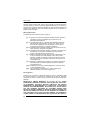
USING THE BC-80X0 RADIO CRADLE
The BC-80X0 cradle, paired with one or more Powerscan™ M8300 readers,
builds a Cordless Reading System for the collection, decoding and transmission
of barcoded data.
It can be connected to a Host PC through an RS-232, USB, Wedge or Pen
cable and is suited for single-cradle point-to-point layouts. It can also be
connected to a C-BOX and therefore integrated into a fixed scanner application.
The BC-8060 models also allow multi-cradle layouts through an RS-485
Network. For this network connection refer to the Powerscan™ D8330/M8300
Reference Manual.
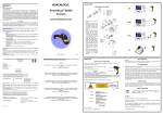
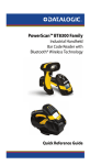
The label on the cradle contains LED indicators and a scan finder button.
When the button is pressed, the cradle transmits a “broadcast” message. All
properly configured scanners (Radio RX Timeout set to keep the radio “awake”)
that are linked to that base (through a bind or a join sequence) and within radio
range coverage will emit a beep sequence once every 2 seconds for 30
seconds. This functionality is useful to:
- verify which scanners are linked to a certain base station
- detect a scanner forgotten somewhere
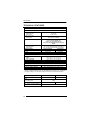
The LEDs signal the BC-80X0 status, as described in the following table:
LED
STATUS
Aux
Yellow On = BC-80X0 is powered through an external power supply.
Yellow Blinking = BC-80X0 transmission occurs over the Host port.
Host
Yellow On = BC-80X0 is powered by the Host.
Yellow Blinking = BC-80X0 transmission occurs over the Host port.
Reader
Green On = the reader battery is completely charged.
Red On = the reader battery is charging.
Orange Blinking = reader battery fault – replace battery.
Red / Green Alternatively Blinking = charging error - see Ref. Manual
Spare*
Green On = the spare battery is completely charged.
Red On = the spare battery is charging.
Orange Blinking = spare battery fault – replace battery.
Red / Green Alternatively Blinking = charging error - see Ref. Manual
* This LED refers to the accessory SBS-8000 Spare Battery Slot when mounted to the BC-8060. Not
available for BC-8010 models.
Figure 1 – Cradle Overview
Figure 2 – LEDs
1
DATALOGIC
To set up your BC-80X0 cradle you must:
1. Physically install the cradle.
2. Make all system connections.
3. Configure the BC-80X0 cradle.
INSTALLATION
MOUNTING THE BC-80X0 CRADLE
The cradle package contains the following items:
BC-80X0
1 horizontal base
BC-80X0 Quick Reference Guide
2 wall-mounting lock hinges
BC-8000 Antenna
4 rubber feet
2 adhesive strips
1 inclined base
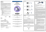
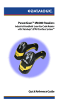
The cradle can be mounted for portable or fixed desktop usage, or it can be
fixed to a wall. The horizontal base allows portable and fixed desktop usage,
while the inclined base provides desktop and wall mounting guaranteeing a
comfortable handling of the Powerscan™ M8300 reader.
BC-80X0 Cradle mounted on the Horizontal Base
BC-80X0 Cradle mounted on the Inclined Base
2
BC-80X0
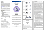
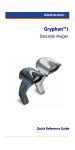
Desktop mounting
For desktop usage, you can mount the cradle either on the horizontal base, for
reduced overall dimensions, or on the inclined base for a more ergonomic taking
out and insertion of the reader onto the cradle.
Horizontal base
Rubber Foot
Seat (4)
Mounting
Tabs (4)
Mounting
Holes (2)
Adhesive
Strip Seat (2)
Cable
Channels
Top View
Bottom View
Inclined base
Mounting
Tabs (4)
Adhesive
Strip Seat (2)
Rubber
Foot Seat (4)
Cable
Channels
Mounting
Holes (4)
Top View
Bottom View
3
DATALOGIC
PORTABLE DESKTOP USE
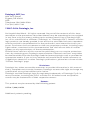
1.
Correctly position the BC-80X0 onto the base by sliding it along the
mounting tabs until aligned.
1
1
2
2
2.
Carefully clean the rubber foot seats of the base to remove any impurities
that could reduce adhesion.
3.
Remove the protective plastic from the rubber feet and stick them onto the
bottom surface of the base.
4.
If mounting the BC-80X0 cradle, insert the antenna in the appropriate hole
on the body of the cradle and screw it clockwise until tight.
FIXED DESKTOP USE
For fixed desktop installation, use the adhesive strips or fixing screws (not
provided) according to your needs.
For mounting with adhesive strips:
1.
Position the cradle onto the base by sliding it along the mounting tabs until
aligned.
2.
Carefully clean the adhesive strip seats of the base to remove any
impurities that could reduce adhesion.
3.
Remove the protective plastic from one side of the adhesive strips and
stick them onto the base surface.
4.
Position the cables to be connected to the BC-80X0 cradle along the
dedicated channels, as shown in the figures below:
Horizontal Base
4
Inclined Base
BC-80X0
5.
Remove the plastic from the other side of the strips and affix the base to
the table.
6.
If mounting the BC-80X0 cradle, insert the antenna in the appropriate hole
on the body of the cradle and screw it clockwise until tight.
For mounting with screws:
1.
Position the cables to be connected to the BC-80X0 cradle along the
dedicated channels, as shown in the figures below:
2.
Position the base on the table and affix it by means of the screws (not
provided).
3.
Position the cradle on the base by sliding it along the mounting tabs until
aligned.
4.
If mounting the BC-80X0 cradle, insert the antenna in the appropriate hole
on the body of the cradle and screw it clockwise until tight.
Wall Mounting
1.
Remove the yellow caps and insert the two wall mounting lock hinges
provided with your cradle.
5
DATALOGIC
2.
Position the cables to be connected to the BC-80X0 cradle along the
dedicated channels (see figures at page 4).
If using the adhesive strips:
If using the mounting screws:
3.
Carefully clean the adhesive strip
seats of the base to remove any
impurities that could reduce
adhesion.
3.
Using the mounting holes on the
base as a pattern, mark the wall
where you desire to mount the
BC-80X0.
4.
Remove the protective plastic
from one side of the adhesive
strips and stick them onto the
base surface.
4.
Drill the appropriate size holes
and insert the threaded dowels
(not provided) into the holes.
5.
Remove the plastic from the
other side of the strips and affix
the base to the wall as indicated
in the figure below.
5.
Position the base on the wall as
indicated in the figure below and
affix it by means of the screws
(not provided).
Inclined Base Wall-mounting
6.
Attach the cradle on the base by sliding it along the mounting tabs until
aligned.
7.
If mounting the BC-80X0 cradle, insert the antenna in the appropriate hole
on the body of the cradle and screw it clockwise until tight.
6
BC-80X0
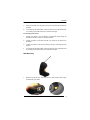
APPLYING RAPID
LABEL (OPTIONAL)
POINT-TO-POINT
CONFIGURATION
A pre-printed barcode label is included in the
package for rapid configuration of point-topoint applications. If you wish to use this
method, apply this label to the seat provided
on the BC-80X0 cradle as shown in the
figure. See the Powerscan™ M8300 Quick
Reference Manual for the configuration
procedure.
SYSTEM CONNECTIONS
Connections should always be made with power off!
CAUTION
The BC-80X0 cradle provides two interface connectors and a power supply
connector as shown in the figure on the next page:
Power Supply
RS-485
(BC-8060 only)
MULTI-INTERFACE
RS-232, USB, Wedge,
PEN Emulation
The RS-485 Network connection is available only on BC-8060 models. For
details about this type of connection, refer to the Powerscan™ D8330/M8300
Reference Manual.
To connect the BC-80X0 cradle to the Host through the multi-interface
connector, use the cable corresponding to the desired interface type.
7
DATALOGIC
CONNECTING AND
INTERFACE CABLE
DISCONNECTING
THE
BC-80X0
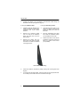
The BC-80X0 can be connected to a Host by means of an RS-232, USB, Wedge
or Pen cable, which must be simply plugged into the Host connector, visible on
the front panel of the cradle.
To disconnect the cable, insert a paper clip or other similar object into the hole
corresponding to the Host connector on the body of the cradle. Push down on the
clip while unplugging the cable. Refer to the following figure:
Multi-standard
interface
RS-232, USB, WEDGE, or
PEN Emulation to Host
Power
Connecting/Disconnecting the Cable
RS-232
USB
8
BC-80X0
WEDGE
PEN
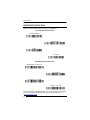
C-BOX
Powerscan™ M
JOIN
Scanner
C-BOX
BIND
BC-80X0
System cables to Host
9
DATALOGIC
BC-80X0 CONFIGURATION
The BC-80X0 configuration can be performed in three ways: by using the
Datalogic Aladdin™ software configuration program, by sending configuration
strings from the Host PC via the RS-232 or USB-COM interface or by reading
configuration barcodes with the Powerscan™ M reader.
DATALOGIC ALADDIN™
Datalogic Aladdin™ is a multi-platform utility program providing a quick and
user-friendly configuration method via the RS-232/USB-COM interface.
It also allows upgrading the software of the connected device (see the Datalogic
Aladdin™ Help On-Line for more details).
SERIAL CONFIGURATION
By connecting the BC-80X0 to a PC through an RS-232 or USB-COM interface
cable it is possible to send configuration strings from the PC to BC-80X0.
CONFIGURATION BARCODES
Once you have performed system connection and Powerscan™ M reader
configuration, you can configure the BC-80X0 cradle by reading configuration
barcodes. Apply power to the BC-80X0.
For Powerscan™ M configuration, refer to the “Powerscan™ M8300 Quick
Reference”.
To configure the BC-80X0 using the Powerscan™ M reader (the one paired to the
cradle with the Bind command), follow the procedure according to the interface
selected.
RESTORE DEFAULT
RESTORE BC-80X0 DEFAULT
Ì$+RX0$-qÎ
To change the defaults refer to the "Powerscan™ D8330/M8300 Reference
Manual", or to the Datalogic Aladdin™ Configuration program, both
downloadable from the website.
10
BC-80X0
INTERFACE SELECTION
Select one of the interface codes according to your application.
USB INTERFACE SELECTION
USB-KBD
Ì$+UA03$-:Î
USB-KBD – ALT-mode
Ì$+UA04$-@Î
USB-COM*
Ì$+UA02$-4Î
USB-IBM-Hand Held
Ì$+UA01$-.Î
USB-IBM Table top
Ì$+UA00$-(Î
USB KBD-APPLE
* When configuring USB-COM, the relevant files and drivers must be installed
from the USB Device Installation Software, which can be downloaded from
the web site http://www.scanning.datalogic.com.
PEN EMULATION INTERFACE SELECTION
PEN
Ì$+CP6$-BÎ
11
DATALOGIC
INTERFACE SELECTION
Select one of the interface codes according to your application.
RS-232 INTERFACE SELECTION
RS-232 Standard
Ì$+CP0$-$Î
Nixdorf Mode A
Ì$+CM2EC0$->Î
Fujitsu
Ì$+CM1$-ÈÎ
ICL Mode
Ì$+CM0$-ÃÎ
WEDGE INTERFACE SELECTION
Wedge IBM AT or PS/2 PCs
Ì$+CP500$-aÎ
PC Notebook
Ì$+CP505$-ÈÎ
PC Notebook - ALT mode
Ì$+CP508$-2Î
IBM AT - ALT mode
Ì$+CP507$-+Î
Interfaces for IBM XT and IBM Terminals 3151, 347X and 348X can be selected
from the PowerScan D8330/M8300 Reference Manual available online at
http://www.datalogic.com.
12
BC-80X0
KEYBOARD NATIONALITY
USB-KBD and Wedge users should select one of the following wedge
keyboard nationality codes according to your keyboard.
Belge
Ì$+FJ7$-8Î
Deutsch
Ì$+FJ3$-$Î
English
Ì$+FJ4$-)Î
Español
Ì$+FJ6$-3Î
Français
Ì$+FJ2$-ÊÎ
Italiano
Ì$+FJ1$-ÅÎ
Svenskt
Ì$+FJ5$-.Î
USA (Default)
Ì$+FJ0$-|Î
13
DATALOGIC
The following Keyboard Nationality selections are only valid for IBM AT
compatible PCs:
Japanese
Ì$+FJ8$-=Î
Russian (Latin)
Ì$+FJ9$-BÎ
Russian (Cyrillic)
Ì$+FJA$-jÎ
Hungarian
Ì$+FJB$-oÎ
Slovenian, Croatian, Serbian (Latin)
Ì$+FJC$-tÎ
Romanian
Ì$+FJD$-yÎ
Czech Republic
Ì$+FJE$-~Î
14
BC-80X0
DATA FORMAT TERMINATORS
For your convenience, some common Terminators are given below. For other
Header/Terminators selections, Data Format and Advanced Data Format
parameters see the Powerscan™ D8330/M8300 Reference Manual.
CR-LF
Ì$+EA120D0A$-ÃÎ
Enter
Ì$+EA1183$-0Î
Tab
Ì$+EA1184$-8Î
None
Ì$+EA10$-dÎ
15
DATALOGIC
BC-80X0 DEFAULT CONFIGURATION
USB-KBD DEFAULT SETTINGS
USA keyboard, FIFO enabled, inter-character and inter-code delays disabled,
USB keyboard speed normal.
DATA FORMAT:
code identifier disabled, code length not transmitted, character
replacement disabled, reader and cradle address stamping disabled, reader and
cradle address delimiter disabled, time stamping disabled, time stamping
delimiter disabled, no header, terminator = ENTER.
RS-232 DEFAULT SETTINGS
9600 baud, no parity, 8 data bits, 1 stop bit, no handshaking, ack/nack protocol
disabled, FIFO enabled, delay disabled, 5 sec. rx timeout
DATA FORMAT:
code identifier disabled, code length not transmitted, character
replacement disabled, reader and cradle address stamping disabled, reader and
cradle address delimiter disabled, time stamping disabled, time stamping
delimiter disabled, no header, terminator = CR-LF.
WEDGE DEFAULT SETTINGS
USA keyboard, Caps Lock off, Caps Lock Auto-Recognition enabled, num lock
unchanged, inter-character and intercode delay disabled, control character
emulation = ctrl+shift+key.
DATA FORMAT:
code identifier disabled, code length not transmitted, character
replacement disabled, reader and cradle address stamping disabled, reader and
cradle address delimiter disabled, time stamping disabled, time stamping
delimiter disabled, no header, terminator = ENTER.
PEN DEFAULT SETTINGS
Interpret operating mode, conversion to code 39, output level normal, idle level
normal, minimum output pulse 600 s, overflow medium, inter-block delay
disabled.
NETWORK PARAMETERS
RS-485 network disabled (for BC-8000 only).
16
BC-80X0
OPERATING TEST
Read the TEST codes below.
EAN-8
1234 5670
EAN-13
1 234567 000992
Code 39 (Normal)
Code 39 (Normal)
1
7
1
6
2
Code 128
t
e
s
t
Interleaved 2 of 5
0123456784
YOUR SYSTEM IS NOW READY TO READ CODES AND TO SEND THE
DATA TO THE HOST.
17
DATALOGIC
TECHNICAL FEATURES
BC-80X0
Electrical Features
Supply Voltage
External Power
Host Power
Power Consumption
External Power
Host Power
Indicators
Time of Recharge
External Power
Host Power
10..30 VDC
5 VDC ±10%
max. 10 W (charging) *
max. 500 mA (charging)
Ext. Power/Data yellow LED
Host Power/Data yellow LED
Reader batt. state green/red LED
Spare batt. state green/red LED (BC-8060 only)
beeper
max. 4 hours with 2150 mAh Li-Ion battery
max. 10 hours with 2150 mAh Li-Ion battery
Radio Features
European Models
USA Models
Radio frequency
Bit Rate
Range (in open air)
433.92 MHz
19200 baud
50 m
910 MHz
36800 baud
30 m
Environmental Features
Working Temperature
Radio
Battery Charging
Storage Temperature
Humidity
Protection Class
-20° to +50 °C / -4° to +122 °F
0° to +40 °C / +32° to +104 °F
-20° to +70 °C / -4° to +158 °F
90 % non condensing
IP40
Mechanical Features
Weight without mounting base
Dimensions (without antenna)
Material
about 380 g / 13.4 oz
240 x 108 x 95 mm / 9.44 x 4.25 x 3.74 in
ABS
* Having a switching regulator inside, the BC-80X0 draws the same power, regardless of
the supply voltage. i.e. as the input voltage increases the current drawn decreases.
System Configuration
Max number of devices per base
station
Max number of devices in the
same reading area
BC-80X0
STARGATE™
32
255
2000
BC-8060
Max number of base stations in
network
18
STARGATE™
16 (including cradle Master)
BC-80X0
WARRANTY
DATALOGIC ADC LIMITED FACTORY WARRANTY
Warranty Coverage
Datalogic warranties this product against defects in workmanship and materials,
for a period of 3 years from the date of shipment, provided that the product is
operated under normal and proper conditions.
Datalogic ADC (“Datalogic”) hardware products are warranted against defects in
material and workmanship under normal and proper use. The liability of
Datalogic under this warranty is limited to furnishing the labor and parts
necessary to remedy any defect covered by this warranty and restore the
product to its normal operating condition. Repair or replacement of product
during the warranty does not extend the original warranty term. Products are
sold on the basis of specifications applicable at the time of manufacture and
Datalogic has no obligation to modify or update products once sold.
If Datalogic determines that a product has defects in material or workmanship,
Datalogic shall, at its sole option repair or replace the product without additional
charge for parts and labor, or credit or refund the defective products duly
returned to Datalogic. To perform repairs, Datalogic may use new or
reconditioned parts, components, subassemblies or products that have been
tested as meeting applicable specifications for equivalent new material and
products. Customer will allow Datalogic to scrap all parts removed from the
repaired product. The warranty period shall extend from the date of shipment
from Datalogic for the duration published by Datalogic for the product at the
time of purchase (Warranty period). Datalogic warrants repaired hardware
devices against defects in workmanship and materials on the repaired assembly
for a 90 day period starting from the date of shipment of the repaired product
from Datalogic or until the expiration of the original warranty period, whichever
is longer. Datalogic does not guarantee, and it is not responsible for, the
maintenance of, damage to, or loss of configurations, data, and applications on
the repaired units and at its sole discretion can return the units in the “factory
default” configuration or with any software or firmware update available at the
time of the repair (other than the firmware or software installed during the
manufacture of the product). Customer accepts responsibility to maintain a back
up copy of its software and data.
Warranty Claims Process
In order to obtain service under the Factory Warranty, Customer must notify
Datalogic of the claimed defect before the expiration of the applicable Warranty
period and obtain from Datalogic a return authorization number (RMA) for return
of the product to a designated Datalogic service center. If Datalogic determines
Customer’s claim is valid, Datalogic will repair or replace product without
additional charge for parts and labor. Customer shall be responsible for
packaging and shipping the product to the designated Datalogic service center,
with shipping charges prepaid. Datalogic shall pay for the return of the product
to Customer if the shipment is to a location within the country in which the
Datalogic service center is located. Customer shall be responsible for paying all
19
DATALOGIC
shipping charges, duties, taxes, and any other charges for products returned to
any other locations. Failure to follow the applicable RMA policy, may result in a
processing fee. Customer shall be responsible for return shipment expenses for
products which Datalogic, at its sole discretion, determines are not defective or
eligible for warranty repair.
Warranty Exclusions
The Datalogic Factory Warranty shall not apply to:
(i) any product which has been damaged, modified, altered, repaired or
upgraded by other than Datalogic service personnel or its
authorized representatives;
(ii) any claimed defect, failure or damage which Datalogic determines
was caused by faulty operations, improper use, abuse, misuse,
wear and tear, negligence, improper storage or use of parts or
accessories not approved or supplied by Datalogic;
(iii) any claimed defect or damage caused by the use of product with any
other instrument, equipment or apparatus;
(iv) any claimed defect or damage caused by the failure to provide proper
maintenance, including but not limited to cleaning the upper
window in accordance with product manual;
(v) any defect or damage caused by natural or man-made disaster such
as but not limited to fire, water damage, floods, other natural
disasters, vandalism or abusive events that would cause internal
and external component damage or destruction of the whole unit,
consumable items;
(vi) any damage or malfunctioning caused by non-restoring action as for
example firmware or software upgrades, software or hardware
reconfigurations etc.;
(vii) the replacement of upper window/cartridge due to scratching, stains
or other degradation and/or
(viii) any consumable or equivalent (e.g., cables, power supply,
batteries, keypads, touch screen, triggers etc.).
No Assignment
Customer may not assign or otherwise transfer its rights or obligations under
this warranty except to a purchaser or transferee of product. No attempted
assignment or transfer in violation of this provision shall be valid or binding upon
Datalogic.
DATALOGIC'S LIMITED WARRANTY IS IN LIEU OF ALL OTHER
WARRANTIES, EXPRESS OR IMPLIED, ORAL OR WRITTEN, STATUTORY
OR OTHERWISE, INCLUDING, WITHOUT LIMITATION, ANY IMPLIED
WARRANTIES OF MERCHANTABILITY, FITNESS FOR A PARTICULAR
PURPOSE, OR NONINFRINGEMENT. DATALOGIC SHALL NOT BE LIABLE
FOR ANY DAMAGES SUSTAINED BY CUSTOMER ARISING FROM
DELAYS IN THE REPLACEMENT OR REPAIR OF PRODUCTS UNDER THE
ABOVE. THE REMEDY SET FORTH IN THIS WARRANTY STATEMENT IS
THE CUSTOMER’S SOLE AND EXCLUSIVE REMEDY FOR WARRANTY
CLAIMS. UNDER NO CIRCUMSTANCES WILL DATALOGIC BE LIABLE TO
20
BC-80X0
CUSTOMER OR ANY THIRD PARTY FOR ANY LOST PROFITS, OR ANY
INCIDENTAL, CONSEQUENTIAL IN-DIRECT, SPECIAL OR CONTINGENT
DAMAGES REGARDLESS OF WHETHER DATALOGIC HAD ADVANCE
NOTICE OF THE POSSIBILITY OF SUCH DAMAGES.
Risk of Loss
Customer shall bear risk of loss or damage for product in transit to Datalogic.
Datalogic shall assume risk of loss or damage for product in Datalogic’s
possession. In the absence of specific written instructions for the return of
product to Customer, Datalogic will select the carrier, but Datalogic shall not
thereby assume any liability in connection with the return shipment.
SERVICE AND SUPPORT
Datalogic provides several services as well as technical support through its
website. Log on to www.datalogic.com and click on the links indicated for
further information including:
PRODUCTS
Search through the links to arrive at your product page where you can
download specific Manuals and Software & Utilities including:
- Datalogic Aladdin™, a multi-platform utility program that allows device
configuration using a PC. It provides RS-232 interface configuration as
well as configuration barcode printing.
SERVICE & SUPPORT
- Technical Support - Product documentation and programming guides
and Technical Support Department in the world
- Service Programs
Agreements
-
Warranty
Extensions
and
Maintenance
- Repair Services - Flat Rate Repairs and Return Material Authorization
(RMA) Repairs.
- Downloads – Manuals & Documentation, Data Sheets, Product
Catalogues, etc.
CONTACT US
Information Request Form and Sales & Service Network
21
DATALOGIC
COMPLIANCE
This device must be opened by qualified personnel only.
POWER SUPPLY
This device is intended to be supplied by a UL Listed/CSA Certified Power Unit
marked "Class 2" or LPS power source rated 10-30 V DC, minimum 1 A, which
supplies power directly to the cradle.
FCC COMPLIANCE
Modifications or changes to this equipment without the expressed written
approval of Datalogic could void the authority to use the equipment.
This device complies with PART 15 of the FCC Rules. Operation is subject to
the following two conditions: (1) This device may not cause harmful
interference, and (2) this device must accept any interference received,
including interference which may cause undesired operation.
This device contains FCC ID U4F0015.
RADIO COMPLIANCE
Contact the competent authority responsible for the management of radio
frequency devices of your country to verify any possible restrictions or licenses
required.
Refer to the web site http://europa.eu.int/comm/enterprise/rtte/spectr.htm for
further information.
22
BC-80X0
COFETEL MEXICO STATEMENTS
Cofetel Mexico Update
Este producto es usable en México
Certificado Nr. RCPDAST08-0269 (COFETEL).
Cofetel Mexico Update
Este producto es usable en México
Certificado Nr. RCPDAST09-0861 (COFETEL).
BRAZILIAN CERTIFICATION STATEMENT
(01)07898916345048
“Este equipamento opera em caráter secundário,
isto é, não tem direito a proteção contra
interferência prejudicial, mesmo de estações do
mesmo tipo, e não pode causar interferência a
sistemas operando em caráter primário.”
23
DATALOGIC
24
BC-80X0
WEEE COMPLIANCE
Waste Electrical
Statement
and
Electronic
Equipment
(WEEE)
English
For information about the disposal of Waste Electrical and Electronic Equipment
(WEEE), please refer to the website at www.datalogic.com.
Italian
Per informazioni sullo smaltimento delle apparecchiature elettriche ed
elettroniche consultare il sito Web www.datalogic.com.
French
Pour toute information relative à l’élimination des déchets électroniques
(WEEE), veuillez consulter le site internet www.datalogic.com.
German
Informationen zur Entsorgung von Elektro- und Elektronik- Altgeräten (WEEE)
erhalten Sie auf der Webseite www.datalogic.com.
Spanish
Si desea información acerca de los procedimientos para el desecho de los
residuos del equipo eléctrico y electrónico (WEEE), visite la página Web
www.datalogic.com.
Portuguese
Para informações sobre a disposição de Sucatagem de Equipamentos Elétricos
e Eletrônicos (WEEE -Waste Electrical and Electronic Equipment), consultar o
site web www.datalogic.com.
Chinese
有关处理废弃电气电子设备 (WEEE)的信息, 请参考 Datalogic
公司的网站:www.datalogic.com。
Japanese
廃電気電子機器(WEEE)の処理についての関連事項はDatalogicのサイト
www.datalogic.com,
をご参照下さい。
25
DATALOGIC
NOTES
26
BC-80X0
NOTES
27
DATALOGIC
NOTES
28
DECLARATION OF CONFORMITY
13
Datalogic ADC Srl, Via S. Vitalino, 13
Lippo di Calderara di Reno (BO) 40012 Italy
EC-051
Rev.: 3
Pag.: 1 di 1
La presente dichiarazione di conformità è rilasciata sotto la responsabilità esclusiva di Datalogic ADC Srl
per:
This Declaration of Conformity is issued under the sole responsibility of Datalogic ADC Srl for:
Cette déclaration de conformité est établie sous la seule responsabilité de Datalogic Srl pour:
Diese Konformitätserklärung wird unter der alleinigen Verantwortung des Datalogic ADC Srl erteilt für:
Esta declaración de conformidad se expide bajo la exclusiva responsabilidad de Datalogic ADC Srl para:
BC-80X0, RF Base Charger
e tutti i suoi modelli
and all its models
et tous ses modèles
und seine Modelle
y todos sus modelos
sono conformi alle Direttive del Consiglio Europeo sottoelencate:
are in conformity with the requirements of the European Council Directives listed below:
sont conformes aux spécifications des Directives de l'Union Européenne ci-dessous:
den nachstehenden angeführten Direktiven des Europäischen Rats:
cumple con los requisitos de las Directivas del Consejo Europeo, según la lista siguiente:
1999/5/EC - R&TTE Directive
2011/65/EU - RoHS Directive
Questa dichiarazione è basata sulla conformità dei prodotti alle norme seguenti:
This declaration is based upon compliance of the products to the following standards:
Cette déclaration repose sur la conformité des produits aux normes suivantes:
Diese Erklärung basiert darauf, daß das Produkt den folgenden Normen entspricht:
Esta declaración se basa en el cumplimiento de los productos con las siguientes normas:
ETSI EN 301 489-3 V1.4.1, AUGUST 2002 :
ELECTROMAGNETIC COMPATIBILITY AND RADIO SPECTRUM MATTERS
(ERM); ELECTROMAGNETIC COMPATIBILITY (EMC) STANDARD FOR RADIO
EQUIPMENT AND SERVICES; PART 3: SPECIFIC CONDITIONS FOR SHORTRANGE DEVICES (SRD) OPERATING ON FREQUENCIES BETWEEN 9KHZ
AND 40GHZ
EN 301 489-1 V1.8.1, APRIL 2008 :
ELECTROMAGNETIC COMPATIBILITY AND RADIO SPECTRUM MATTERS
(ERM); ELECTROMAGNETIC COMPATIBILITY (EMC) STANDARD FOR
RADIO EQUIPMENT AND SERVICES; PART 1: COMMON TECHNICAL
REQUIREMENTS
ETSI EN 300 220-2 V2.1.2, JUNE 2007 :
ELECTROMAGNETIC COMPATIBILITY AND RADIO SPECTRUM MATTERS
(ERM); SHORT RANGE DEVICES (SRD); RADIO EQUIPMENT TO BE USED
IN THE 25MHZ TO 1000MHZ FREQUENCY RANGE WITH POWER LEVELS
RANGING UP TO 500MW; PART 2: HARMONIZED EN COVERING ESSENTIAL REQUIREMENTS UNDER ARTICLE 3.2 OF THE R&TTE DIRECTIVE
EN 60950-1, APRIL 2006 +
A11:2009+A1:2010 + A12:2011:
INFORMATION TECHNOLOGY EQUIPMENT - SAFETY PART 1 : GENERAL REQUIREMENTS
EN 50581, SEPTEMBER 2012 :
TECHNICAL DOCUMENTATION FOR THE ASSESSMENT OF ELECTRICAL AND
ELECTRONIC PRODUCTS WITH RESPECT TO THE RESTRICTION OF HAZARDOUS SUBSTANCES
Lippo di Calderara, March 29th , 2013
RUGGERO CACIOPPO
QUALITY & RELIABILITY MANAGER - EUROPE
www.datalogic.com
©2007-2014 Datalogic, Inc. • All rights reserved.
Datalogic and the Datalogic logo are registered trademarks
of Datalogic S.p.A. in many countries, including the U.S.A.
and the E.U.
Datalogic ADC, Inc.
959 Terry Street | Eugene |OR 97402 | USA
Telephone: (1) 541-683-5700 | Fax: (1) 541-345-7140
820042814
(Rev D)
February 2014