1
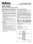
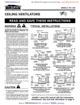
::bathroomsource.com
Call 1-800-667-8721 anywhere in the US and Canada - www.bathroomsource.com
INSTALLATION INSTRUCTIONS
READ & SAVE THESE INSTRUCTIONS!
Wall Heater
MODELS: 192, 194, 198
IMPORTANT SAFETY INSTRUCTIONS
PLAN THE INSTALLATION
WARNING – TO REDUCE THE RISK OF FIRE, ELECTRIC
SHOCK, OR INJURY TO PERSONS, OBSERVE THE FOLLOWING:
1. All electrical work must be done in accordance with local or
national electrical code as applicable. For safety, this product
must be grounded. If you are unfamiliar with methods of installing electrical wiring, secure the services of a qualified electrician.
2. When wiring, servicing or cleaning this unit, turn off power and
lock out service panel. Failure to do so could allow others or
thermostat to turn on power unexpectedly which may cause
fatal electrical shock.
3. To avoid electrical shock:
• Do not install unit in a tub or shower enclosure or any location where it may come in contact with water.
• Never place a switch where it can be reached from a tub or
shower.
4. Do not install this unit in an area where chemicals and other
flammables are stored or used. Explosion and fire may result.
This heater is intended to be used to supply supplemental heat
from a wall location in new or existing construction.
Choose a location where edge of heater will be at least 12" from
the floor or any adjacent vertical surface.
The heater can be operated using its built-in thermostat or a remote thermostat (Choose either the Model 86W Line-Voltage thermostat or use the Model 82 Transfomer/Relay with an appropriate
low-voltage thermostat.). The Model 85 Kit is available for surfacemount applications. Purchase these accessories separately.
Plan to supply the heater with proper line voltage and appropriate
power cable.
NOTE: Power can be tapped from a nearby circuit depending on
the heater wattage required and the amperage rating of the circuit.
Heater can be converted to half-wattage to avoid overloading such
circuits.
MODEL
192
194
198
CAUTION
VOLTS
240
240
240
AMPS
8.33/4.17
12.50/6.25
16.67/8.33
WATTS
BTU/HR
2000/1000 6827/3413
3000/1500 10240/5120
4000/2000 13653/6827
Bold ratings are factory wired.
See “OPTIONAL WIRING CONVERSIONS” section for wattage
conversion instructions.
1. This product may ONLY be installed in a wall. Do not mount in
any other position.
2. Install heater at least 12" from floor or any adjacent vertical
surface.
3. Do not locate heater behind a door, furniture, drapes, etc.,
where the air flow to the unit would be restricted.
4. Provide heater with an appropriately-rated electrical circuit to
prevent tripped breakers or blown fuses.
5. Do not connect heater to dimmer switch or speed control.
6. To avoid motor bearing damage and noisy and/or unbalanced
impellers, keep drywall spray, construction dust, etc., off power
unit.
7. Please read specification label on product for further information and requirement.
Refer to FIGURE 1
Follow these basic steps when installing this heater:
1) Nail housing to studs.
2) Connect power cable.
3) Fasten heater assembly and grille to housing.
DRYWALL
THERMAL
OVERLOAD
HEATER HOUSING
GRILLE
BUILT-IN
THERMOSTAT
POWER CABLE
FIGURE 1
1
Broan at
::bathroomsource.com
is a division of
kitchen::accessories
U
N
L
I
M
I
T
E
D
::bathroomsource.com
Call 1-800-667-8721 anywhere in the US and Canada - www.bathroomsource.com
INSTALL THE HEATER
Refer to FIGURE 2
1. Remove heater assembly from housing. Take out the four (4)
screws shown and set heater assembly aside.
Refer to FIGURE 3
2. Attach housing to wall studs.
NOTE: Locate housing at least 12" from floor on any adjacent walls.
Use the measuring guides on the sides of housing to position housing so that it will be flush with finished wall. Nail the housing to
studs through the hole and slot on both sides of housing.
NOTE: In 24"-on-center stud construction, framing in between studs
is necessary.
THERMAL
OVERLOAD
“RESET”
BUTTON
HEATER
ASSEMBLY
MOUNTING
SCREWS
THERMOSTAT
WIRE THE HEATER
FIGURE 2
Refer to FIGURE 4
1. Connect power cable to housing. Attach electrical power cable
to housing using appropriate connector. Allow 6" of wire inside
housing. Secure ground wire to housing with grounding clip, as
shown.
Refer to FIGURE 5 and FIGURE 6
2. Wire the heater assembly. Connect wires from heater assembly to power cable wires. Follow wiring diagram.
If heater is wired direct, use the built-in thermostat for temperature control.
NAIL HERE –
BOTH SIDES
MEASURING
GUIDES
OPTIONAL WIRING CONVERSIONS
When using a separate wall control, simply turn the heater's builtin thermostat to its highest setting. There is no need to disconnect
the built-in thermostat:
a) Turn built-in thermostat to highest setting.
b) Remove knob.
c) Fasten security cover to grille.
FIGURE 3
LINE-VOLTAGE THERMOSTAT
Refer to FIGURE 7
If wall-mounted control is desired, use the Model 86W Line-Voltage Thermostat. Purchase thermostat separately.
Cut blue wire. Strip ” of insulation from each end. Connect wires
from wall control to each stripped wire.
GROUNDING CLIP DETAIL
LOW-VOLTAGE THERMOSTAT
If wall-mounted control is desired, use a Model 82 Transfomer/
Relay with an appropriate low-voltage thermostat (purchase separately). Follow the mounting and wiring instructions packed with
the controls.
FIGURE 4
HALF-WATTAGE CONVERSION
Refer to FIGURE 8
The heater will produce less heat and use less electricity if converted to half-wattage. Remove the black jumper wire from the
heating element and discard wire.
FIGURE 5
2
Broan at
::bathroomsource.com
is a division of
kitchen::accessories
U
N
L
I
M
I
T
E
D
Call 1-800-667-8721 anywhere in the US and Canada - www.bathroomsource.com
COMPLETE THE INSTALLATION
T1
1. Install housing mask. A housing mask has been provided to
keep construction dust, drywall spray, paint, etc., from damaging the heater. Bend the flap on the mask and push it into the
heater housing.
NOTE: Mask can be put into place before or after heater assembly
is reinstalled. Remove mask before operation.
2. Reinstall heater assembly. Secure heater assembly to housing
with four (4) screws. Check thermal overload button marked
"RESET". Heater will not operate unless this button is depressed.
Refer to FIGURE 9
3. Install grille. Place grille over heater and attach with four (4)
screws. Push knob onto thermostat stem.
4. Attach security cover to grille (optional). When heater is installed
in a public area without a separate wall control, it is recommended that:
a) Built-in thermostat be set to desired temperature level.
b) Thermostat knob be removed.
c) Security cover be attached to grille with two (2) screws, provided.
5. Check operation. Turn on power at service entrance. Turn thermostat to its highest setting and make sure heating element
and blower come on. Then turn it to its lowest setting and make
sure element and blower shut off.
NOTE: The fan delay prevents the fan from coming on until the
element is hot. Likewise, it keeps the fan running until the element
cools down.
BLACK JUMPER
T2
BLK
HEATING ELEMENT
THERMAL
OVERLOAD
BLK
BLK
BLK
MOTOR
THERMOSTAT
FAN
DELAY
RED
BLK
BLU
FACTORYWIRED
HEATER
240/208 VAC
LINE IN
T1
BLACK JUMPER
T2
BLK
HEATING ELEMENT
THERMAL
OVERLOAD
BLK
FAN
DELAY
USE AND CARE
CAUTION – DISCONNECT POWER AT SERVICE ENTRANCE
AND LOCK OUT PANEL BEFORE CLEANING OR SERVICING
UNIT.
Thermal Overload Protector
Your heater is equipped with a manual-reset thermal overload protector. If heater fails to operate when thermostat is turned to its
highest setting:
1) Turn off power at service entrance.
2) Remove knob and grille.
3) Press button marked "RESET".
This type of device is particularly useful (compared to automatic
reset devices) because it encourages the user to find and correct
the cause of overheating unit when resetting the protector.
To avoid property damage when using this heater to prevent freezeups:
Make sure heater functions properly before leaving unattended. A
tripped protector will prevent the heater from operating.
Cleaning
Clean the heater using the round brush tool on your vacuum cleaner.
Remove large accumulatoins of dust, lint, etc., that might impede
the flow of air through the heater. Such blockage will lower its efficiency and create a possible overheating condition.
To clean grille, use a soft cloth which has been moistened with
household window cleaner.
CAUTION – METAL AND ELECTRICAL PARTS SHOULD NEVER
BE IMMERSED IN WATER.
FACTORYWIRED
HEATER
➙
RED
BLU
CUT WIRE
FOR
REMOTE
THERMOSTAT
240/208 VAC
LINE IN
FIGURE 7
TOP / FRONT
OF HEATER
REMOVE THIS
JUMPER WIRE
HEATER CONVERTED TO HALF-WATTAGE
FIGURE 8
FIGURE 9
3
::bathroomsource.com
MOTOR
BLK
BLK
THERMOSTAT
Broan at
FIGURE 6
BLK
::bathroomsource.com
is a division of
kitchen::accessories
U
N
L
I
M
I
T
E
D
::bathroomsource.com
Call 1-800-667-8721 anywhere in the US and Canada - www.bathroomsource.com
PARTS LIST
REF.
1
2
3
4
5
PART
NUMBER
6
7
8
9
10
11
12
97009334
99390015
99030190
98006989
99271155
99270723
99270724
99400061
97008688
97008690
*
*
97008692
99150491
13
14
15
20
97008683
93270619
99260425
99160350
21
22
23
24
25
26
99030324
99080251
99080249
99020255
97013822
99150478
27
29
30
31
*
99090683
99360136
99110687
93150462
97013945
WARRANTY
BROAN-NUTONE ONE YEAR LIMITED WARRANTY
Broan-NuTone warrants to the original consumer purchaser of our
products that such products will be free from defects in materials or
workmanship for a period of one year from date of original purchase.
THERE ARE NO OTHER WARRANTIES, EXPRESSED OR IMPLIED,
INCLUDING, BUT NOT LIMITED TO, IMPLIED WARRANTIES OR
MERCHANTABILITY OR FITNESS FOR A PARTICULAR PURPOSE.
During this one-year period, Broan-NuTone will, at our option, repair
or replace, without charge, any product or part which is found to be
defective under normal use and service.
THIS WARRANTY DOES NOT EXTEND TO FLUORESCENT LAMP
STARTERS AND TUBES. This warranty does not cover (a) normal
maintenance and service or (b) any products or parts which have
been subject to misuse, negligence, accident, improper maintenance
or repair (other than by us), faulty installation or installation contrary
to recommended installation instructions.
The duration of any implied warranty is limited to the one-year period
as specified for the express warranty. Some states do not allow
limitation on how long an implied warranty lasts, so the above limitation may not apply to you.
BROAN-NUTONE’S OBLIGATION TO REPAIR OR REPLACE, AT
OUR OPTION, SHALL BE THE PURCHASER'S SOLE AND EXCLUSIVE REMEDY UNDER THIS WARRANTY. Broan-NuTone
SHALL NOT BE LIABLE FOR INCIDENTAL, CONSEQUENTIAL OR
SPECIAL DAMAGES ARISING OUT OF OR IN CONNECTION WITH
PRODUCT USE OR PERFORMANCE. Some states do not allow the
exclusion or limitation of incidental or consequential damages, so the
above limitations or exclusion may not apply to you.
This warranty gives you specific legal rights, and you may also have
other rights, which vary from state to state. This warranty supersedes all prior warranties.
To qualify for warranty service, you must (a) notify us at an address
or telephone number below, (b) give the model number and part
identification and (c) describe the nature of any defect in the product
or part. At the time of requesting warranty service, you must present
evidence of the original purchase date.
Broan-NuTone LLC
926 West State Street
Hartford, WI 53027
(1-800-637-1453)
PART DESCRIPTION
Housing
Grounding Clip
Fan Delay
Element Bracket (2 Required)
Heating Element (Model 192)
Heating Element (Model 194)
Heating Element (Model 198)
Bushing
Black Wire Assembly (29–1/2")
Black Jumper Wire
Thermal Overload Bracket
Thermal Overload
Red Power Wire
Screw, 8–18 x 3/8 Ph. Pan Head
(14 Required)
Partition Plate Assembly
Wire Clamp ( 3 Required)
Nut, 8–32 Hex Keps (2 Required)
Screw, 6–32 x 1/4 Ph. Pan Head
(2 Required)
Thermostat
Motor (Model 198)
Motor (Models 192 & 194)
Fan Blade
Grille
Screw, 8–18 x 3/8 PH Truss Hd.
(4 Required)
Grille Logo
Knob
Security Cover
Screw, 8–18 x 5/8 Oval Head (2 Required)
Assembly, Thermal Overload (Includes Key
Nos. 9, 10, & 12 (2))
Product specifications
subject to change
without notice.
4
Broan at
::bathroomsource.com
is a division of
99043273B
kitchen::accessories
U
N
L
I
M
I
T
E
D