1
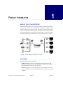
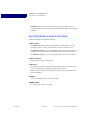
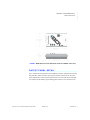
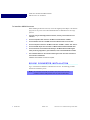
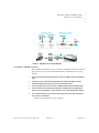
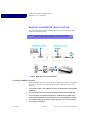
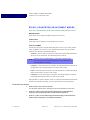
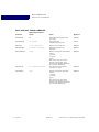
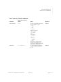
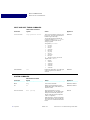
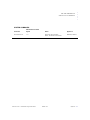
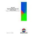
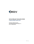
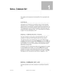
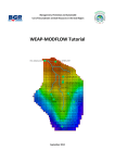
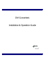
DVI Converters:
Installation & Operation Guide
BDV
BLACK DIAMOND VIDEO
Edition 1.02
March 2010
Edition 1.02
DVI Converters: Installation & Operation Guide
.....
Contents
...................................
Chapter 1
Product Information ....................................1
About DVI Converters ............................................ 1
Options .................................................................... 1
Key Features & Specifications ................................ 2
Output Panel Detail ................................................. 2
Video Input Detail ................................................... 3
Customer Service and Support ................................ 4
Chapter 2
Installation Instructions
..........................5
SD-DVI Converter Installation ................................ 5
SDI-DVI Converter Installation .............................. 6
RGB-DVI Converter Installation ............................ 8
RS-232 Control ........................................................... 9
Chapter 3
Using the Control Buttons
....................11
About the Control Buttons ........................................ 11
Selecting Adjustment Modes .................................... 12
RGB-DVI Converter Adjustment Modes.................. 13
SD-DVI Converter Adjustment Modes ..................... 14
Restoring Factory Defaults .................................... 15
Auto Increment & Decrement ............................... 16
Appendix A
RS-232 Protocol ........................................17
DVI Converters Command Set ................................. 17
DVI Converters: Installation & Operation Guide
Edition 1.02
Contents i
ii
Contents
Edition 1.02
DVI Converters: Installation & Operation Guide
P RODUCT I NFORMATION
.....
...................................
1
....................................................
ABOUT DVI CONVERTERS
Black Diamond Video offers a line of single-link, externally or phantom-powered DVI
converters which you can use to convert your RGB, SD, and SDI video signals to singlelink DVI. With the appropriate DVI converter, you can use any of these alternate video
formats as an input source for Black Diamond Video digital video processing equipment.
The system diagram (Figure 1) illustrates the full functionality of a DVI processor when
combined with Black Diamond Video's DVI Converters and DVI X-treme Cable Kits.
FIGURE 1.
System diagram using DVI Converters
....................................................
OPTIONS
The following DVI converters are available:
• SD-DVI Converter converts any standard-definition analog signal (NTSC, PAL,
SECAM) to DVI. This converter is controlled and integrates seamlessly with Black
Diamond Video digital video processing equipment.
• SDI-DVI Converter converts any serial digital interface signal (SDI) to DVI. This
converter is integrates seamlessly with Black Diamond Video digital video processing
equipment.
DVI Converters: Installation & Operation Guide
Edition 1.02
Introduction 1
PRODUCT INFORMATION
Key Features & Specifications
• RGB-DVI Converter converts any analog RGB signal to DVI. This converter is
controlled and integrates seamlessly with Black Diamond Video digital video processing
equipment.
....................................................
KEY FEATURES & SPECIFICATIONS
Features and specifications include the following:
VIDEO INPUT
• The SD-DVI Converter accepts any standard-definition analog signal (NTSC, PAL,
SECAM). Connectors: 3 BNCs: Composite Video, S-Luma, S-Chroma; Y,Cb,Cr.
• The SDI-DVI Converter accepts any serial digital interface signal (SDI). Connector: 75
Ohm BNC input connector; DVI-D, 75 Ohm BNC output connector for loop-through.
• The RGB-DVI Converter accepts any analog RGB signal. Connector: DB15 RGB.
VIDEO OUTPUT
• Single-link DVI. Connector: DVI Female.
CONTROL
• RS-232 serial control of the of the RBG-DVI and SD-DVI Converters. Connector: RJ11.
An RJ11 to DB9 female serial cable is included with all converters.
• Manual control of the RBG-DVI and SD-DVI Converters using external mode setting
and selection buttons.
POWER
• Converters are equipped with a +5V AC/DC adapter.
DIMENSIONS
• 4.6” length x 2.69” width x 1.07” height.
2
Introduction
Edition 1.02
DVI Converters: Installation & Operation Guide
Output Panel Detail
FIGURE 2.
.....
PRODUCT INFORMATION
RGB-DVI Converter dimensions (same for all BDV converters)
....................................................
OUTPUT PANEL DETAIL
Figure 2 details the DVI output panel of the RGB-DVI, SD-DVI, and SDI-DVI Converters.
This panel also contains the power input connector and the Link status LED. The Link
status LED indicates a variety of status and functions by the color and pattern of the light.
For example, the LED flashes a green blinking pattern when an active connection to the
DVI Converters: Installation & Operation Guide
Edition 1.02
Introduction 3
PRODUCT INFORMATION
Video Input Detail
converter is established, and a red blinking pattern to indicate that an active video input
connection exists.
FIGURE 3.
DVI output panel
....................................................
VIDEO INPUT DETAIL
Figure 3 details the video input panel of the RGB-DVI Converter.
FIGURE 4.
4
Introduction
RGB/YUV input panel of the RGB-DVI Converter
Edition 1.02
DVI Converters: Installation & Operation Guide
Customer Service and Support
.....
PRODUCT INFORMATION
Figure 4 details the video input panel of the SD-DVI Converter.
FIGURE 5.
Input panel of the SD-DVI Converter
Figure 5 details the video input panel of the SDI-DVI Converter.
FIGURE 6.
Input panel of the SDI-DVI Converter
....................................................
CUSTOMER SERVICE AND SUPPORT
For technical support and service, contact Black Diamond Video at:
Black Diamond Video
1000 Atlantic Ave., Ste. 114
Alameda, California, 94501
Phone: (510) 769-2959
Fax: (510) 769-2949
Visit us on the web at www.blackdiamondvideo.com.
DVI Converters: Installation & Operation Guide
Edition 1.02
Introduction 5
PRODUCT INFORMATION
Customer Service and Support
6
Introduction
Edition 1.02
DVI Converters: Installation & Operation Guide
I NSTALLATION I NSTRUCTIONS
.....
...................................
2
This chapter tells you how to install your SD-DVI, SDI-DVI, or RGB-DVI converter.
IMPORTANT!
This product must be tested with the intended equipment
before being permanently installed. Failure to do so voids any
warranty and limited liability. Although Black Diamond
Video tests the product to its fullest extent, situations may
arise giving marginal results or potential compatibility issues
when used with digital video display devices that are noncompliant or incompatible.
....................................................
SD-DVI CONVERTER INSTALLATION
Figure 6 illustrates the installation of the SD-DVI converter. The following procedure
describes the installation process.
NOTE: DVI Converters should be connected as close to the video source as
possible to minimize cable problems such as noise and attenuation.
FIGURE 6.
DVI Converters: Installation & Operation Guide
SD-DVI Converter installation
Edition 1.02
Introduction 5
INSTALLATION INSTRUCTIONS
SDI-DVI Converter Installation
To Install the SD-DVI Conver ter
Before installing the SD-DVI converter, connect the supplied power adapter to the unit and
plug it into an AC power source. Black Diamond Video recommends the use of a surge
protector.
1
If you are using an externally-powered converter, connect your transformer to the
converter.
2
Connect composite video sources to the BNC connector labeled “Y/CVBS”.
3
Connect S-Video sources to the BNC connectors labeled “Cb/S-Y” and “Cr/S-C”
4
Connect component sources to the BNC connectors “Y/CVBS”, “Cb/S-Y” and “Cr/S-C”.
5
Connect the DVI output of the converter to a Black Diamond Video-tested DVI cable.
6
Connect the other end of the DVI cable directly to the Black Diamond Video digital
video processing equipment in your installation, such as the Phantom 800 or CXPS.
7
The Link LED indicator on the converter flashes green when an active connection to
the converter is established.
Installation of the SD-DVI Converter is complete.
....................................................
SDI-DVI CONVERTER INSTALLATION
Figure 7 illustrates the installation of the SDI-DVI converter. The following procedure
describes the installation process.
NOTE: DVI Converters should be connected as close to the video source as
possible to minimize cable problems such as noise and attenuation.
6
Introduction
Edition 1.02
DVI Converters: Installation & Operation Guide
SDI-DVI Converter Installation
FIGURE 7.
.....
INSTALLATION INSTRUCTIONS
SDI-DVI Converter installation
To Install the SDI-DVI Converter
Before installing the SDI-DVI converter, connect the supplied power adapter to the unit and
plug it into an AC power source. Black Diamond Video recommends the use of a surge
protector.
1
Connect the 75 Ohm Serial Digital Interface source to the BNC connector labeled SDI
Input.
2
If desired, connect a 75 Ohm Serial Digital Interface output to the BNC connector
labeled SDI Output for loop-through connection to the SDI source.
3
Connect the DVI output of the converter to a Black Diamond Video-tested DVI cable.
4
Connect the other end of the DVI cable directly to the Black Diamond Video digital
video processing equipment in your installation, such as the Phantom 800 or CXPS.
5
The Link LED indicator on the converter flashes green when an active connection to
the converter is established.
Installation of the SDI-DVI Converter is complete.
DVI Converters: Installation & Operation Guide
Edition 1.02
Introduction 7
INSTALLATION INSTRUCTIONS
RGB-DVI Converter Installation
....................................................
RGB-DVI CONVERTER INSTALLATION
Figure 8 illustrates the installation of the RGB-DVI converter. The following procedure
describes the installation process.
NOTE: DVI Converters should be connected as close to the video source as
possible to minimize cable problems such as noise and attenuation.
FIGURE 8.
RGB-DVI Converter installation
To Install the RGB-DV I Converter
Before installing the SD-DVI converter, connect the supplied power adapter to the unit and
plug it into an AC power source. Black Diamond Video recommends the use of a surge
protector.
1
Connect 3 wire, 4 wire, or 5 wire RGB or YUV source to the DB15 HD connector labelled
“RGB/YUV”.
2
Connect the DVI output of the converter to a Black Diamond Video-tested DVI cable.
3
Connect the other end of the DVI cable directly to the Black Diamond Video digital
video processing equipment in your installation, such as the Phantom 800 or CXPS.
4
The Link LED indicator on the converter flashes green when an active connection to
the converter is established.
8
Introduction
Edition 1.02
DVI Converters: Installation & Operation Guide
RS-232 Control
.....
INSTALLATION INSTRUCTIONS
Installation of the RGB-DVI Converter is complete.
....................................................
RS-232 CONTROL
Set up of the RGB-DVI and SD-DVI converters should be done using RS-232 control. The
following procedure details how to establish RS-232 serial control with the DVI converter.
To establish RS -232 control of the DVI converter
1
Connect the supplied RJ11 to DB9 cable to the DVI converter.
2
Connect the control computer to the RS-232 DB9 connector on the supplied cable. DVI
Converters.
3
Open up a serial port terminal on the control computer.
On Microsoft Windows, you can use HyperTerminal for serial communications.
4
Configure the port settings as follows:
• Baud: 9600
• Data bits: 8
• Parity: None
• Stop bits: 1
• Flow control: None
The RS-232 connection to the DVI Converters is established and the converter can be controlled using the RS-232 command set found in Appendix A, “RS-232 Protocol.”
NOTE: To avoid recreating the connection parameters each time you reestablish
RS-232 connection to the CXPS, you can save the connection for
subsequent control sessions.
DVI Converters: Installation & Operation Guide
Edition 1.02
Introduction 9
INSTALLATION INSTRUCTIONS
RS-232 Control
10
Introduction
Edition 1.02
DVI Converters: Installation & Operation Guide
3
U SING THE C ONTROL B UTTONS
.....
...................................
This chapter tells you how to use the control buttons on the RGB-DVI and SD-DVI
Externally-Powered Converters.
....................................................
ABOUT THE CONTROL BUTTONS
The RGB-DVI and SD-DVI Externally-Powered Converters have three buttons you can use
to modify settings on the devices. The buttons are labeled down (−), up (+), and Menu.
Figure 9 shows the top of the converters and the three control buttons.
The Link LED, located on the DVI output panel, flashes in different colors and patterns to
indicate the current mode setting.
NOTE: You can also use RS-232 control to control the Converter. See
Appendix A, “RS-232 Protocol,” for details.
FIGURE 9.
Control buttons on an externally-powered converter
NORMAL OPERATION MODE
When either of the two converters is in normal operation mode, the LED flashes in a pattern
of two blinks, followed by three blinks, followed by four blinks. The LED color is red if the
device is locked to an input or green if the device does not detect a valid input.
DVI Converters - Installation & Operation Guide
Edition 1.01
Operation
11
USING THE CONTROL BUTTONS
Selecting Adjustment Modes
ADJUSTMENT MODES
You can use the control buttons to modify various settings on the Externally-Powered
Converters. The buttons are used to enter the different adjustment modes, such as Modulus
and Horz. Position for the RGB-DVI Converter and Saturation and Contrast for the SD-DVI
Converter, and make setting changes.
....................................................
SELECTING ADJUSTMENT MODES
The adjustment modes and how to select them are listed in the following table. For more
information about the adjustment modes, see “RGB-DVI Converter Adjustment Modes” on
page 13 and “SD-DVI Converter Adjustment Modes” on page 14.
Adjustment Mode:
RGB-DVI Converter
Adjustment Mode:
SD-DVI Converter
LED pattern/color
Auto
Increment &
Decrement?a
Modulus
Brightness
Rapid Red blink
Yes
+
Phase
Contrast
Rapid Green blink
Yes for SD
− and +
Test Pattern
Input Format
Steady Green b
No
Press and Hold 3
Seconds to Enter
Mode
.−. . . . . . . . . . . . . . . . . . . . . . . . . . . . . . . . . . . . . . . . . . . . . . . . . . . . . . . . . . . . . . . .
Menu and
−
Horiz. Position
Saturation
Red, Red, Green
Yes for SD
Menu and
+
Vert. Position
Hue
Green, Green, Red
Yes for SD
Menu and
+ and −
Test Pattern Rotate
N/A
Steady Green
No
Restore Factory
Defaults
Restore Factory
Defaults
Steady Red c
No
Menu
a. For more information on Auto Increment & Decrement, see “Auto Increment & Decrement” on page 16.
b. For the SD-DVI Converter, the LED pattern/color is Steady Green if the unit is in AutoSense mode. However, depending on the Input Format
setting (see below), the LED is Steady Green but may flicker several times every 3-4 seconds.
c. The Restore Factory Defaults mode is special, but begins with the LED pattern and color in Steady Red mode. See “Restoring Factory Defaults”
on page 15.
To Select an Adjustment Mode
•
To enter an adjustment mode that allows you to modify one of the device settings, hold
one or more buttons down for three seconds.
When the device is in the new setting mode, the LED blink pattern and/or color changes.
For example, if you want to change the input modulus on an RGB to DVI converter unit,
press and hold the Down (−) button until the LED blink pattern changed to a rapid red
12
Operation
Edition 1.01
DVI Converters - Installation & Operation Guide
RGB-DVI Converter Adjustment Modes
.....
USING THE CONTROL BUTTONS
blinking pattern (about 3 seconds). At this point, the up and down buttons would set the
modulus up and down.
NOTE: The changes that these adjustment modes make to the device can be seen
immediately, but the changes are not be stored to non-volatile memory
until you exit the adjustment mode and return to the normal operation
mode. If the unit is powered off before the normal mode is re-entered, the
changes made in the last adjustment mode are lost.
To Exit an Adjustme nt Mode
•
To exit any of the adjustment modes, hold down the Menu button until the normal
operation mode LED blink pattern returns (about 3 seconds).
....................................................
RGB-DVI CONVERTER ADJUSTMENT MODES
There are six adjustment modes for the RGB-DVI Externally-Powered Converter.
MODULUS
Use this adjustment mode to modify the modulus applied to the RGB input signal.
PHASE
Use this adjustment mode to modify the phase applied to the RGB input signal.
TEST PATTERN
The RGB converter unit can generate nine different test patterns. In Test Pattern mode, you
can select the output test pattern to be generated. The default output resolution is 640 x 480.
Additional output resolutions are available via serial command. (See the
inputtestpattern command in Appendix A, “RS-232 Protocol.”)
HORIZONTAL POSITION
In this mode, you can adjust the horizontal position of the RGB input relative to the output.
VERTICAL POSITION
In this mode, you can adjust the vertical position of the RGB input relative to the output.
TEST PATTERN ROTATE
In this mode, each of the nine test patterns are displayed at a resolution of 640 x 480. Each
test pattern remains on the output for approximately five seconds.
DVI Converters - Installation & Operation Guide
Edition 1.01
Operation 13
USING THE CONTROL BUTTONS
SD-DVI Converter Adjustment Modes
....................................................
SD-DVI CONVERTER ADJUSTMENT MODES
There are five adjustment modes specific to the SD-DVI Externally-Powered Converter:
BRIGHTNESS
In this mode, you can adjust the brightness setting for the converter.
CONTRAST
In this mode, you can adjust the contrast setting for the converter.
INPUT FORMAT
The SD-DVI Converter has an input format setting that can be set to one of four possible
values. By default, your converter is set to AutoSense input format. You can tell which
format has been selected by the LED blink pattern:
• AutoSense - detects if either a composite or svideo signal is present and automatically
selects the correct input format. The LED blink pattern is solid red.
NOTE: Autosense, due to hardware limitations, cannot detect component video
input. If you are using a component video input, you must set the input
format specifically to Component.
• Composite - sets the input format to Composite. The LED blink pattern is solid red, but
the light flickers off once approximately every three to four seconds.
• Svideo - sets the input format to SVideo. The LED blink pattern is solid red, but the light
flickers off two times every three to four seconds.
• Component - sets the input format to Component. The LED blink pattern is solid red,
but the light flickers off three times every three to four seconds.
Setting the device to either Composite, Svideo, or Component will disable AutoSense mode
and force the particular input setting, even if no signal is present in that input format.
To Set the Input Format
1
Press and hold - and
+ for three seconds.
The LED pattern is Steady Green, indicating the input format adjustment mode is active.
2
Press the + button to move up through the format settings, from AutoSense to
Composite, from Composite to Svideo, or from Svideo to Component.
3
Press the − button, to move down through the format settings, from Component to
Svideo, Svideo to Composite, or Composite to AutoSense.
14
Operation
Edition 1.01
DVI Converters - Installation & Operation Guide
Restoring Factory Defaults
.....
USING THE CONTROL BUTTONS
The input format list does not “wrap around.” Once you have reached the top of the list (Component) Pressing the + button is ignored. LIkewise, once you are at the bottom of the list
(AutoSense), - button presses are ignored.
4
Verify which format you selected by observing the blink pattern of the Link LED. See
“Input Format” on page 14 for a description of these patterns.
5
To exit the input format adjustment mode, hold down the Menu button until the normal
operation mode LED blink pattern returns (about 3 seconds).
SATURATION
Use this mode to adjust the saturation setting for the converter.
HUE
In this mode, you can adjust the hue setting for the converter.
....................................................
RESTORING FACTORY DEFAULTS
This is the only adjustment mode that is shared by both the RGB- and SD-DVI Externally
Powered Converters. In this mode, you can reset the device to the state that the firmware
was in when it left the factory.
IMPORTANT!
Using this mode resets any settings that have been saved, and for the
RGB-DVI Converter, deletes all saved hosts!
To Restore Factory De faults
1
Press the Menu button.
When this mode is entered, the LED will be Steady Red.
2
To confirm you wish to restore factory defaults, press and hold the + button until the
LED changes to a pattern of blinking red.
3
To reconfirm you still would like to continue, press and hold the - button until the LED
changes to a pattern of fast blinking red.
4
Finally, if you are absolutely sure you want to continue, send your last confirmation by
pressing and holding the Menu button.
The converter performs the Restore Factory Defaults action and then restarts.
NOTE: Pressing the wrong button in any of the pre-restore states causes the
Restore Factory Defaults action to abort, taking the unit back to the normal
operating mode.
DVI Converters - Installation & Operation Guide
Edition 1.01
Operation 15
USING THE CONTROL BUTTONS
Auto Increment & Decrement
....................................................
AUTO INCREMENT & DECREMENT
For each adjustment mode that allows Auto Increment & Decrement (see “Selecting
Adjustment Modes” on page 12, pressing and holding the + or − button for more than about
a half second causes the setting to increment or decrement approximately four times per
second. You can press and hold the adjustment button for continuous adjustment to the
setting.
For adjustment modes that do not have Auto Increment & Decrement, you must do one
button press for each incremental change to a setting.
16
Operation
Edition 1.01
DVI Converters - Installation & Operation Guide
A
RS-232 P ROTOCOL
.....
...................................
....................................................
DVI CONVERTERS COMMAND SET
The RGB-DVI and SD-DVI DVI Converters are controlled by using RS-232 protocol. No
adjustments may be made to the SDI-DVI Converter. Commonly used commands are
presented and defined in the following tables covering image control, input and host timing
control, and general system commands.
Arguments in [square brackets] are optional. Arguments in <angle brackets> are required.
For example, typing bri by itself returns the current brightness setting. Typing bri 0 sets
the brightness level to 0. Typing inputsave with no arguments returns an error because
the inputsave command requires the <inputnum> argument.
Commands can be entered using either the full command name or the abbreviated syntax.
For example, to set the brightness level to 25, you could type either brightness 25 or
bri 25.
NOTE: RS-232 commands are not case-sensitive. Capitalization of either the
commands or the parameters does not matter.
IMAGE CONTROL COMMANDS
Abbreviated Command
Syntax
Action
Applies To
BRIGHTNESS
bri [+/-100]
Sets brightness level.
RGB-DVI; SD-DVI
CONTRAST
cont [0-200]
Sets contrast level.
RGB-DVI; SD-DVI
HUE
hue [+/-180]
Sets hue level.
SD-DVI
SATURATION
sat [0-200]
Sets saturation level.
SD-DVI
............ .................. ...................... ............
Command
INPUT AND HOST TIMING COMMANDS
Command
Abbreviated Command
Syntax
Action
Applies To
HOSTLIST
HLIST [hostnum]
Displays one or all default hosts.
RGB-DVI
............ .................. ...................... ............
DVI Converters - Installation & Operation Guide
Edition 1.01
Reference 17
RS-232 PROTOCOL
DVI Converters Command Set
INPUT AND HOST TIMING COMMANDS
Command
Abbreviated Command
Syntax
HOSTMATCH
............ .................. ...................... ............
18
Action
Applies To
HM
Lists all hosts that match the current
input timing.
RGB-DVI
INPUTFORMAT
if [format]
Sets input format to
composite/svideo/component
SD-DVI
INPUTLIST
inlist [inputnum]
Displays one or all input hosts.
RGB-DVI
INPUTLISTDEL
inlistdel <inputnum>
Deletes the input host at slot
<inputnum>.
RGB-DVI
INPUTMODULUS
inmod
Interactively changes the input modulus.
Controls:
(-) decrease
(+) increase
(q) quit
Note: when you type these control
characters, nothing appears on the
terminal screen, though the adjustments
are visible in the output image.
RGB-DVI
INPUTNAME
inn <inputnum> <name>
Sets a name for the input host slot
<inputnum> to <name>.
RGB-DVI
INPUTPHASE
inph
Interactively changes the input phase.
Controls:
(-) decrease
(+) increase
(q) quit
Note: when you type these control
characters, nothing appears on the
terminal screen, though the adjustments
are visible in the output image.
RGB-DVI
Reference
Edition 1.01
DVI Converters - Installation & Operation Guide
DVI Converters Command Set
.....
RS-232 PROTOCOL
INPUT AND HOST TIMING COMMANDS
Command
Abbreviated Command
Syntax
INPUTPOSITION
INPUTSAVE
............ .................. ...................... ............
Action
Applies To
inpos
Interactively changes the input position.
Position adjustment controls:
j - left
l - right
i - up
m - down
H/V active adjustment:
M,L - increase
I,J - decrease
H step:
H - increase
h - decrease
V step:
V - increase
v - decrease
q - quit
Note: when you type these control
characters, nothing appears on the
terminal screen, though the adjustments
are visible in the output image.
RGB-DVI
ins <inputnum>
Saves the current host to NVRAM at
<inputnum>. Valid slot numbers are
<0...31>.
RGB-DVI
DVI Converters - Installation & Operation Guide
Edition 1.01
Reference 19
RS-232 PROTOCOL
DVI Converters Command Set
INPUT AND HOST TIMING COMMANDS
Command
Abbreviated Command
Syntax
INPUTTESTPATTERN
intp <pattern> <host>
............ .................. ...................... ............
Action
Applies To
Turns on the test pattern <pattern> with
host <host>. The converter generates an
RGB host signal internally.
To turn the test pattern generator off,
issue the command intp 15 <host>.
Although it is required, the <host>
setting is ignored.
Test patterns <pattern>:
RGB-DVI
0
1
2
3
4
5
6
7
8
15
color bars
grey ramp
red ramp
green ramp
blue ramp
grey steps
red steps
green steps
blue steps
Turns the test pattern generator off
Output modes <host>:
0
1
2
3
4
5
INPUTTIMING
int
800x600
1024x768
1388x1024
1600x1200
1920x1080
1920x1200
Returns the input timing. If a valid input
signal is not present, no values are
returned.
RGB-DVI
SYSTEM COMMANDS
Command
Abbreviated Command
Syntax
Action
Applies To
HELP
help
Lists all user commands.
RGB-DVI; SD-DVI
ID
id
Returns system information: model,
manufacturing date, serial number, and
firmware version.
RGB-DVI; SD-DVI
INPUTAUTOSENSE
inas [on/off]
Turns input autosense on or off.
When autosense is on, the SD-DVI unit
attempts to automatically identify the
format of the input signal (component,
svideo, or composite).
When autosense is off, the format of the
input signal must be set using either the
INPUTFORMAT command or the Menu
button.
SD-DVI
............ .................. ...................... ............
20
Reference
Edition 1.01
DVI Converters - Installation & Operation Guide
DVI Converters Command Set
.....
RS-232 PROTOCOL
SYSTEM COMMANDS
Command
Abbreviated Command
Syntax
RESTOREDEFAULT
rfd
............ .................. ...................... ............
DVI Converters - Installation & Operation Guide
Action
Applies To
Restores the factory defaults.
NOTE: This deletes all stored hosts.
RGB-DVI; SD-DVI
Edition 1.01
Reference 21
RS-232 PROTOCOL
DVI Converters Command Set
22
Reference
Edition 1.01
DVI Converters - Installation & Operation Guide