1
®
EL
917.37281
OWNER'S MANUAL
Convert!
bee
oAssembny
o Operation
o Customer
Responsibilities
o Service
o Adjustments
o Repair Parts
Caution:
Read and Follow
all Safety Rules
and Instructions
Before Operating
This Equipment
146303
10/11/94
Printed in U.SoA°
SAFETY RULES
CAUTION: ALWAYS DISCONNECT SPARK PLUGWIRE AND PLACEWIRE WHERE IT CANNOTCONTACT SPARK
PLUG TO PREVENT ACCIDENTAL STARTING WHEN SETTING UP, TRANSPORTING, ADJUSTING OR MAKING
REPAIRS_
iMPORTANT
SAFETY STANDARDS REQUIRE OPERATOR PRESENCE CONTROLS TO MINIMIZE THE RISK OF INJURY° YOUR UNIT IS EQUIPPED WITH
SUCH CONTROLS, DO NOT ATTEMPT TO DEFEAT THE FUNCTION OF THE OPERATOR PRESENCE CONTROLS UNDER ANY CIRCUMSTANCES°
TRAINING:
Always stop the engine whenever you leave or are not using
your mower, or before crossing driveways, walks, roads, and
any gravel-covered areas.
',
Read this operator's manual carefully Become familiar with
the controls and know how to operate your mower properly_
Learn how to quickly stop mower..
*
Do not allow children to use your mower, Never allow adults
to use mower without proper instructions.
o
Never direct discharge of materiat toward bystanders nor'
allow anyone near the mower while you are operating it.
o
Keep the area of operation clear of all persons, especially
small children and pets.'
°
o
Use mower only as the manufacturer
scribed in this manual
Before cleaning, inspecting, or repairing your mower, stop
the engine and make absolutely sure the blade and all
moving parts have stopped Then disconnect the spark plug
wire and keep it away from the spark plug to prevent
accidental starting.
o
Do not operate mower' if it has been dropped or damaged in
any manner. Always have damage repaired before using
your mower.
o
Do not continue to run your mower if you hit a foreign o_jecL
Fotlow the procedure outlined above, then repair any damage before restarting and operating you mower..
o
Do not use accessory attachments that are not recommended
by the manufacturer'.
Use of such attachments may be
hazardou&
o
Do not change the governor settings or overspeed the
engine Engine damage or' personal injury may resuiL
o
Do not operate your mower if it vibrates abnormally.. Excessive vibration is an indication of damage; stop the engine,
safely check for the cause of vibration and repair as required..
o
Do not run the engine indoors Exhaust fumes are dangerous.
o
Never cut grass by pulling the mower towards you. Mow
across the face of slopes, never up and down or you might
lose your footing. Do not mow excessively steep slopes.
Use caution when operating the mower on uneven terrain or
when changing directions - maintain good footing=
Never operate your mower without proper guards, plates,
grass catcher' or other' safety devices in place.
intended and as de-
Be aware that the mower blade turns when the engine is
running..
PREPARATION:
°
Always thoroughly check the area to be mowed and clear it of
all stones, sticks, wires, bones, and other foreign objects
These objects will be thrown by the blade and can cause
severe injury.
°
Always wear safety glasses or eye shields when starting and
while using your mower..
o
o
Dress properly.
Do not operate mower when barefoot or
wearing open sandals
Wear only solid shoes with good
traction when mowing.
MAINTENANCE
=
•
•
Check fuel tank before starting engine. Do not fill gas tank
indoors, when the engine is running or when the engine is hot.
Allow the engine to cool for several minutes before filling the
gas tank Clean off any spilled gasoline before starting the
engine.
AND STORAGE:
o
Check the blade and the engine mounting bolts often to be
sure they are tightened properly,
•
Check all bolts, nuts and screws at frequent intervals for
proper tightness to be sure mower is in safe working condition,
Always make wheel height adjustments before starting your
mower.. Never attempt to do this while the engine is running..
o
Keep all safety devices in place and working,
Mow only in daylight or good artificial lighL
°
To reduce fire hazard, keep the engine free of grass, leaves
or excessive grease and oil.
o
Check grass catcher often for deterioration and wear and
replace worn bags, Use only replacement bags that are
recommended by and comply with specifications of the
manufacturer of your mower,.
°
Atways keep a sharp blade on your mower'.
°
Mow engine to cool before storing in any enclosure
•
Never store mower with fuel in the tank inside a building
where fumes may reach an open flame or an ignition source
such as a hot water heater, space heater, clothes dryer, etc.
OPERATION:
o
Keep your eyes and mind on your mower and the area being
cuL Do not let other interests distract you.,
°
Do not mow wet or slippery grass Never run while operating
your mower_ Always be sure of your footing - keep a firm hold
on the handles and walk.
Do not put hands or' feet near or under rotating part& Keep
clear of the discharge opening at all times
LOOK
FOR - THIS
SYMBOL
IT MEANS
ATTENTION!!!
TO
POINT OUT
IMPORTANT
BECOME
ALERT!!!
YOUR
2
SAFETY IS PRECAUTIONS.
SAFETY
INVOLVED.
PRODUCT
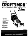
CONGRATULATIONS
on your purchase of a Sears Lawn
Mower. It has been designed, engineered and manufactured to give you the best possible dependability and
performance.
Should you experience any problem you cannot easily
remedy, please contact your nearest Sears Authorized
Service Center/Department.
We have competent, welltrained technicians and the proper tools to service or repair
this lawn mower.
Please read and retain this manual° The instructions will
enable you to assemble and maintain your lawn mower
properly. Always observe the "SAFETY RULES'L
MODEL
NUM BER
9'! 7.372810
SPECUFICATIONS
HORSEPOWER:
6,0
DISPLACEMENT:
12,56 CU, IN,
GASOLINE CAPACITY
AND TYPE:
1,5 QUARTS
UNLEADED REGULAR
OIL TYPE (API-SF/SG):
SAE 30 (ABOVE 32°F)
SAE 5W-30 (BELOW 32°F)
OIL CAPACITY:
28 OZS
SPARK PLUG:
(GAP: _,030")
CHAMPION
STD361458
RJ19-LM
VALVE CLEARANCE:
INTAKE:
EXHAUST:
.,008 IN.,
_,008 IN
SERIAL
NUMBER
SOLID STATE IGNITION
AIR GAP:
o0125 IN,,
DATE OF PU RCHASE
BLADE BOLT TORQUE:
35-40 FT, LBSo
THE MODEL AND SERIAL NUMBERSWILL BE FOUND
ON A DECAL ATTACHED TO THE REAR OF THE
LAWN MOWER HOUSING
YOU SHOU LD RECORD BOTH SERIAL NUMBER AND
DATE OF PURCHASE AND KEEP IN A SAFE PLACE
FOR FUTURE REFERENCE
MAINTENANCE
AGREEMENT
A Sears Maintenance Agreement is available on this product, Contact your nearest Sears store for details°
CUSTOMER
RESPONSIBILITIES
o
Read and observe the safety rules.
°
Follow a regular schedule in maintaining, caring for and using your lawn mower.
•
Follow the instructions under "Customer Responsibilities"
LIMITED TWO
YEAR WARRANTY
and "Storage" sections of this owner's manual°
ON CRAFTSMAN
POWER MOWER
For two years from date of purchase, when this Craftsman Lawn Mower is maintained, lubricated, and tuned up
according to the operating and maintenance instructions in the owner's manual, Sears will repair free of charge any
defect in material or workmanship,
If this Craftsman Lawn Mower is used for commercial or rental purposes, this warranty applies for only 90 days from
the date of purchase,
This Warranty does not cover:
•
Expendable items which become worn during normal use, such as rotary mower blades, blade adapters, belts,
air cleaners and spark plugo
°
Repairs necessary because of operator abuse or negligence, including bent crankshafts and the failure to maintain
the equipment according to the instructions contained in the owner's manual
WARRANTY SERVICE IS AVAILABLE BY RETURNING THE CRAFTSMAN POWER MOWER TO THE NEAREST
SEARS SERVICE CENTER/DEPARTMENT IN THE UNITED STATES. THIS WARRANTY APPLIES ONLY WHILE
THIS PRODUCT IS 1N USE IN THE UNITED STATES.
This Warranty gives you specific legal rights, and you may also have other rights which vary from state to state..
SEARS, ROEBUCK AND CO.., D/817 WA, HOFFMAN ESTATES, ILLINOIS 60179
3
TABLE
OF CONTENTS
SAFETY RULES ............................................................
2
PRODUCT SPECIFICATIONS ......................................
3
CUSTOMER RESPONSIBILITIES ....................... 3, 9-11
WARRANTY ..................................................................
3
ASSEMBLY ...................................................................
5
OPERATION ..................................................................
6
MAINTENANCE SCHEDULE .......................................
9
SERVICE AND ADJUSTMENTS ................................ 12
STORAGE ...................................................................
14
TROUBLESHOOTING .................................................
23
REPAIR PARTS - LAWN MOWER ........................ 15-19
REPAIR PARTS - ENGINE ....................................
20-22
PARTS ORDERING/SERVICE ................................... 24
iNDEX
E
A
Operation:
Accessories ...................................................
5
Engine:
Drive Control ...............................................
7
Air Filter'. .................................. 11
Engine Control ..........................................
7
Adjustments:
Oil Change ............................. 11
Grass Catcher'. ................................
10
Carburetor .....................................
13
Oil Level ...................................................
11
Mower ...............................................................
7
Drive Belt .............................................
12
Oil Type .................................... 11
Operator
Presence
Engine Speed .......................... 13
Starting ..........................................8
Control Bar ..................................................
7
Handle Height ...............................
13
Stopping ................................... 8
Options:
Height of Cut ....................................
7
Storage ..............................................
14
Accessories ..................................................
5
Air Filter:
Replacement ...................................
11
F
R
Service ..................................................
11
Fuel:
Repair Parts:
Assembly .................................................
5
Capacity ................................................................
3
Engine ............................... 20-22
Storage ............................................
14
Lawn Mower ............................
15-19
B
Type ...........................................................................
8
Responsibilities,
Customer
........
3,
9-11
Blade:
H
Sharpening ............................ 10
S
Replacement .......................... 10
Handle Adjustment:
Safety
Rules
..............................................
2
Assembly ..........................................
5
C
Cutting Height ......................... 13
Controls:
Engine Zone Control ....................7
L
Engine Speed Control ....................
6
Lubrication:
Operator' Presence
Engine ....................................... 11
Control Bar ..............................................
6
Lawn Mower ............................ 9
Customer Responsibilities ..... 3, 9-t t
Air Filter .................................... t 1
Blade Care!Replacement ............
10
M
Drive Wheels ..............................10
Maintenance Agreement ................ 3
Engine ................................................
11
Maintenance Schedule ................... 9
Lubrication ......................................
11
Mowing Tips ........................................8
Spark Plug ................................. i 1
Cutting Levels .........................................
7
O
Oil:
Engine .................................................
11
Storage ........................................14
Service and Adjustments ............... 12
Carburetor. .......................................
13
Drive Belt ........................................
I2
Engine Speed ...................................
13
Handle ............................................
13
Spark Plug ...............................................
11
Specifications
................................... 3
Speed Control:
Engine ....................................................
12
Starting the Engine .......................... 8
Stopping the Engine .......................... 8
Storage .................................................
14
T
Trouble Shooting Chart ................. 23
W
Warranty .........................................................
3
4
LAWN
E
ACC
ES
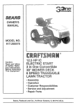
These accessories were available when this lawn mower was produced° They are also available at most Sears retail outlets
and service center& Most Sears stores can also order repair parts for you, when you provide the model number of your lawn
mower. Some of these accessories may not apply to your lawn mower.
ENGINE
IlUlUl,UlIll Ul,Ul,
SPARK PLUG
MUFFLER
AIR FILTER
GASCAN
ENGINE OIL
i
ii
ii
STABILIZER
LAWN MOWER MAINTENANCE
BELT
BLADE
BLADE
ADAPTER
WHEELS
LAWN MOWER
COVER
ASSEMBLY
Read these instructions and this manual in its entirety
before you attempt to assemble or operate your new lawn
mower° Your new lawn mower has been assembled at the
factory with the exception of those parts left unassembled
for shipping purposes° All parts such as nuts, washers,
bolts, etco, necessary to complete the assembly have been
placed in the parts bag, To ensure safe and proper
operation of your lawn mower, all parts and hardware you
assemble must be tightened securely., Use the correct
tools as necessary to ensure proper tightness°
TO REMOVE
LAWN
MOWER
OPERATOR PRESENCE
CONTROLBAR
UPPER HANDLE
LIFT UP
FROM
MOWING POSITION
CARTON
°
Remove loose parts included with mower_,
o
Cut down two end corners of carton and lay end panel
down flat.
o
Remove all packing materials except padding between upper and lower handle and padding hotding
operator presence control bar to upper handle,
Roll lawn mower out of carton and check carton
thoroughly for additional toose parts,
o
HOWTO SET UPYOUR
TO UNFOLD
=
HANDLE
LOWER HANDLE
FIG. 1
Raise upper handle section into place on lower handle,
remove protective padding and tighten both handle
knobs,
LAWN MOWER
(See Fig.
1)
Raise handles until lower handte section locks into
place in mowing position,
5
.
Remove handle padding holding operator presence
control bar to upper handle,,
.
Your lawn mower handle can be adjusted for your
mowing comfort,. See "TO ADJUST HANDLE" in the
Service and Adjustments section of this manual,,
OPERAON
......................
1 ,,,l,,i
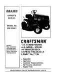
KNOWYOUR
LAWN
MOWF.R
READ THIS OWNER'S MANUAL AND SAFETY RULES BEFORE OPERATING YOUR LAWN MOWER_
Compare the
illustrations
withyour lawn mower tofamiliarize
yourseff
withthelocation
of variouscontrols
and adjustments_Save this
manual for future reference°
ZONE CONTROL
OPERATOR PRESENCE
CONTROLBAR
CABLE
DRIVE CONTROL
LEVER
STARTER HANDLE
HANDLE KNOB
GASOLINE
FILL CAP
ENGINE OIL CAP WITH DIPSTICK
CABLECLIP
ENGINE SPEED
CONTROL LEVER
DISCHARGE
DRIVE COVER
GUARD
MULCHER
PLATE
WHEEL ADJUSTER
(ON EACH WHEEL)
HOUSING
PRIMER
..................................................................
i i i i i i i_ ,_ i,iil,l,,_l,l,,,i
MEETS CPSC SAFETY REQUIREMENTS
Sears rotary walk-behind power lawn mowers conform to the safety standards of the American National Standards Institute
and the UpS°Consumer Product Safety Cornmission_ The blade turns when the engine is runhing.
OPERATOR PRESENCE CONTROL - must be held down
to the handle to start the engine° Release to stop the
engine°
PRIMER - pumps additional fuel from the carburetor' to the
cylinder for use when starting a cold engine.
ENGINE SPEED CONTROL LEVER * located on the side
of the engine which allows you to select either high (_) or
low (-4_) engine speed.
STARTER HANDLE - used for starting the engine,
DRIVE CONTROL LEVER - used to engage power-propelled forward motion of lawn mower.
MULCHER PLATE - located at the discharge opening,
must be removed when converting to bagging or discharging operation.
6
OPERA
0
HOW TO USE YOUR LAWN iVIOWER
ENGINE
SPEED
(See Fig. 2)
The engine speed is controlled by a lever located on the
side of the engine_ High ('_) position is for starting engine,
normal cutting and better grass bagging.
Low (-4_)
position is for light cutting, trimming and fuel economy..
ENGINE
&
•
ZONE
CONTROL
CAUTION: Federal regulations require
an engine control to be installed on this
lawn mower in order to minimize the
risk of blade contact injury. Do not
under any circumstances attempt to
defeat the function of the operator control The blade turns when the engine is
running.
ENGINE SPEED CONTROL
CUTTING
HEIGHT
Raise wheels for low cut and lower wheels for high cut.
°
Wheels are set in tow cut for shipping,. Adjust cutting
height to suit your requirements_ Medium position )s
best for most lawns°
°
To change cutting height, squeeze adjuster lever toward wheel. Move wheel up or down to suit your
requirements,. Be sure all wheels are in the same
setting°
CONTROL
OPERATOR PRESENCE
CONTROL BAR
Self-propelling is controlled by holding the operator
presence control bar down to the handle and pushing
the drive control lever forward until it clicks; then
release the lever,.
o
Forward motion will stop when the operator presence
control baris released,, To stop forward motion without
stopping engine, release the operator presence control
bar slightly until the drive control disengages, Hold
operator presence control bar down to handle to continue mowing without self-propellingo
DRIVE
CONTROL
To keep drive control engaged when turning corners,
push down on handle and lift front wheels off ground
while turning lawn mower..
TO CONVERT
(See Fig. 5)
RAISE WHEELS
FOR LOW CUT
FIG. 3
(See Fig. 4)
°
°
LOWER WHEELS
FOR HIGH CUT
(See Fig. 3)
=
DRIVE
PRIMER
FIG. 2
Your lawn mower is equipped with an operator presence control bar which requires the operator to be
positioned behind the lawn mower handle to start and
operate the lawn mower..
TO ADJUST
LEVER
TO DISCHARGING
CONTROL
TO ENGAGE,
DRIVE CONTROL
DISENGAGED
FIG. 4
MOWER
Your mower is shipped ready to be used as a mulcher_ To
convert to bagging or discharging:
o
Lift discharge guard and remove mulcher plate..
°
Mower can now be used for side discharging or optional grass catcher can be attached.
°
To returnto mulching operation, simplyreinstall mulcher
plate as shown°
_
without discharge guard, approved
grass
CAUTION:
catcher
Do or
notmulcher
run yourplate
lawninmower
place.
:::
iiiiiiiiii i,i ,_
!
FIG. 5
.............
7
MULCHER
PLATE
OPERATION
i
BEFORE
,
,,
i
,,
,i,
,!
!
I
,,
L
,, I
i,,11
I,,IIL,!IIII,,
L
I
I
STARTgNG ENGBNE
GASOLINE
FILLER CAP
OIL (See Fig. 6)
Your lawn mower is shipped without oil in the engine..
.
Be sure mower' is level and area around oil fill is clean_
•
Remove engine oil cap w/dipstick and fill to the full line
on the dipstick_
o Use 28 ozs,. of oil. For type and grade of oil to use, see
"ENGINE" in Customer Responsibilities section of this
manual
.
Pour oil slowly. Do not over fill..
.
Check oil level before each use. Add oil if needed., Fill
to full line on dipstick,
o To read proper level, tighten engine oil cap each time_
°
Reinstall engine oil cap and tighten.
°
After- the first two (2) hours of mowing, change the oil,
and every 25 hours thereafter.
You may need to
change the oi! more often under dusty, dirty conditions_
ENGINE OIL CAP
W/DIPSTICK
FIG. 6
°
o
GAS (See Fig. 6)
°
Fill gasoline tank with fresh, clean, unleaded gasoline..
DO NOT USE PREMIUM GASOLINE BE CAREFUL
NOT TO OVER FILL TANK_
WARNING:
Experience indicates that alcohol blended
fuels (called gasohol or using ethanol or methanol) can
attract moisture which leads to separation and formation of
acids during storage.. Acidic gas can damage the fuel
system of an engine while in storage. To avoid engine
problems, the fuel system should be emptied before storage of 30 days or longer.. Drain the fuel tank, start the
engine and let it run untii fuel lines and carburetor are
empty. Use fresh fuel next season° See Storage Instructions for additional information.
Never use engine or
carburetor cleaner products in fuel tank or permanent
damage may occur..
MAX 113
FIG. 7
MULCHING
TO START ENGINE
°
To start a cold engine, push primer five (5) times before
trying to starL Use a firm push. This step is not usually
necessary when starting an engine which has already
run for a few minutes_
°
Move engine speed control lever to high ('_) position.
°
Hold operator presence control bar down to the handle
and pull starter handle quickly. Do not allow starter
rope to snap back.
°
To stop engine, release operator presence control bar.
NOTE: In cooler weather it may be necessary to repeat
priming steps_ In warmer weather over priming may cause
flooding and engine will not start. If you do flood engine wait
a few minutes before attempting to start and do not repeat
priming steps.,
IVIOWING TIPS
°
°
°
•
Under'certain conditions, such as very tall grass, it may
be necessary to raise the height of cut to reduce
pushing effort and to keep from overloading the engine
and leaving clumps of grass clippings.
For extremely heavy cutting, reduce the width of cut by
overlapping previously cut path and mow slowly_
For' better grass bagging and most cutting conditions,
the engine speed should be set in the high ('_)
position.
For side discharge lawn mowers, cutting in a counter_
clockwise direction, starting at the outside of the area
to be cut, spreads grass clippings more evenly and
puts less load on the engine, To keep clippings off of
walk'ways, flower beds, etc.., make the first cuts in a
clockwise direction,,
Pores in cloth grass catchers can become filled with dirt
and dust with use and catchers will collect less grass°
To prevent this, regularly hose catcher off with water
and let dry before using_
Keep top of engine around starter clear and clean of
grass clippings and chafL This will help engine airflow
and extend engine tife_
8
MOWING
TIPS
IMPORTANT:
FOR BEST PERFORMANCE,
KEEP
MOWER HOUSING FREE OF BUILT-UP GRASS AND
TRASH_
SEE
"CLEANING"
IN
CUSTOMER
RESPONSIBILITIES SECTION OF THIS MANUAL,
= The special mulching blade will recut the grass clippings many times and reduce them in size so that as
they fall onto the lawn they will disperse into the grass
and not be noticed° Also, the mulched grass will
biodegrade quickly to provide nutrients for the lawn.
Always mulch with your highest engine (blade) speed
as this will provide the best recutting action of the
blades.
°
Avoid cutting your lawn when it is weL Wet grass tends
to form clumps and interferes with the mulching action_
The best time to mow your lawn is the early afternoon.
At this time the grass has dried and the newly cut area
will not be exposed to the direct sun,
•
For best results, adjust the lawn mower cutting height
so that the lawn mower cuts off only the top one-third
of the grass blades (See Fig. 7)_ If the lawn is overgrown it will be necessary to raise the height of cut to
reduce pushing effort and to keep from overloading the
engine and leaving clumps of mulched grass. For
extremely heavy mulching, reduce your' width of cut by
overlapping previously cut path and mow slowly.,
°
Certain types of grass and grass conditions may require that an area be mulched a second time to cornpletely hide the clippings, When doing a second cut,
mow across or perpendicular to the first cut path.
°
Change your cutting pattern from week to week. Mow
north to south one weekthen change to east to west the
next week_ This will help prevent matting and graining
of the lawn_
O
IL
,,H_
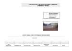
AS YOU COMPLETE
REGULAR
SERVICE
Check for Loose
_
Fasteners
Drive Wheels
Mowers)
sharpen/Replace
Mower
_
6/
(If Equipped)
CJeanilnspect
Grass Catcher
clean Lawn Mower
_[t_!' lnspect/clean
(Self-Propelled
R
f_&;k_J__--_
_¢,_ _
N
Clean Air Filter
Inspect Muffler
N
Replace
Spark
Replace
Air Filter Paper Cartridge
E
1
2
3
4
- Change
- Service
- Replace
_ Charge
,i,,,
E
,11.,11
,i ......
HII,,,,H[
.......
._,_O
i
£
64#
....
,, ,' .....
.....................
6/'
,,
......................
6/'
'
6/' 3
Check
Engine Oil Leve! ...................................................
6/' .......
Change Engine Oil
6/'
G
I
_
6/
6/
i
6/
Lubrication
Chart
Clean Battery/Recharge
.............
!Ele,ctr!c Sted Mowers) .........
E
_'4_
_
6/
Blade .................
ii ....
_,_
,_
............
_1'
6/
6/
6/'4
6/
..................
6/1,2
6/2
6/
Plug
.........................
....
6/
6/2
...................
more often when operating under a heavy load or in high ambient temperatures,
more often when operating in dirty or dusty conditions
blades more often when mowing in sandy soil,
48 hours at end of season
LUBRICATHON CHART
GENERAL
(_) ENGINE OIL
RECOMMENDATIONS
O WHEEL
ADJU==
The warranty on this lawn mower does not cover items that
have been subjected to operator abuse or negligence,. To
recieve full value from the warranty, operator must maintain
mower as instructed in this manual
Some adjustments will need to be made periodically to
properly maintain your unit.
All adjustments in the Service and Adjustments section of
this manual should be checked at least once each season..
•
•
Once a year, replace the spark plug, replace air filter
element and check blade for wear. A new spark plug
and clean!new air filter element assures proper air-fuel
mixture and helps your engine run better and last
longer.
Follow the maintenance
BEFORE
"
•
Check
Check
schedule
/
7
//
in this manual.
EACH USE
engine oil level.
for loose fasteners.
LUBRICATION
Keep unit well lubricated
(See "LUBRICATION
CHART")..
(_
HANDLE BRACKET
MOUNTING PIN
(_
SPRAY LUBRICANT
(_) REFER TO CUSTOMER RESPONSIBILITIES
(_) DISCHARGE
GUARD
HINGE PIN
"ENGINE"
SECTION.
IMPORTANT:
DO NOT OIL OR GREASE PLASTIC WHEEL
BEARINGS..
VISCOUS
LUBRICANTS
WILL ATTRACT
DUST AND DIRT THAT WILL SHORTEN
THE LIFE OF
THE SELF LUBRICATING
BEARINGS. IF YOU FEEL THEY
MUST BE LUBRICATED,
USE ONLY A DRY, POWDERED
GRAPHITE TYPE LUBRICANT
SPARINGLY.
9
CUSTOME
ESPO
LAWN MOWER
Always observe safety rules when performing any maintenance.
TIRES
,
Keep tires free of gasoline, oit, or insect control chemicals which can harm rubber.
°
Avoid stumps, stones, deep ruts, sharp objects and
other hazards that may cause tire damage.
BLADE
B
KEY_J
)__
CARE
For best results, rnower blade must be kept sharp. Replace
bent or damaged blades.
TO REMOVE BLADE (See Fig. 8)
°
Disconnect spark plug wire from spark ptug and place
wire where it cannot come in contact with spark plug.
o
Turn lawn mower' on its side_ Make sure air filter' and
carburetor are up.,
Use a wood btock between blade and mower housing
to prevent blade from turning when removing blade
bolt.
•
•
WASHER
LOCK WASHER
TRAILING
EDGE
k\
BLADE ADAPTER
FIG. 8
GEAR CASE
Protect your hands with gloves and/or wrap blade with
heavy cloth°
Remove blade bolt by turning counter-clockwise. Use
a 9/16" box or open-end wrench_
°
To keep your drive system working properly, the gear
case and area around the drive should be kept clean
and free of trash build-up. Clean under the drive cover
twice a season_
(bolt, lock
°
NOTE: Remove the blade adapter and check the key
inside hub of blade adapter, The key must be in good
condition to work properly. Replace adapter if damaged°
The gear case isfilled with lubricant to the properlevel
at the factory_ The only time the lubricant needs
attention is if service has been performed on the gear
case.,
•
If lubricant is required, use only Texaco Starplex Premium Grease, part no_ 750369 Do not substitute.
•
•
Remove blade and attaching hardware
washer and hardened washer).
TO REPLACE BLADE (See Fig° 8)
°
°
Position blade on the blade adapter aligning the two (2)
holes in the blade with the raised lugs on the adapter'.
•
Be sure the trailing edge of blade (opposite sharp
edge) is up toward the engine_
install the blade bolt with the lock washer and hardened
washer into blade adapter and crankshaft.
Use block of wood between blade and lawn mower
housing and tighten the blade bolt, turning clockwise°
=
°
DRIVE WHEELS
Position the blade adapter on the engine crankshaft
Be sure key in adapter and crankshaft keyway are
aligned_
Check front drive wheels each time before you mow to be
sure they move freely,
The wheels not turning freely means trash, grass cuttings,
etco are in the drive wheel area and must be cleaned to free
drive wheels.
If necessary to clean the drive wheels, check both front
wheels.
= The recommended tightening torque is 35-40 ft. Ibso
IMPORTANT: BLADE BOLT IS GRADE 8 HEAT TREATED.
NOTE: We do not recommend sharpening
you do, be sure the blade is balanced°
blade - but if
°
Remove hubcaps, hairpin cotters and washers.
°
Remove wheels from wheel adjusters_
o
Remove any trash or grass cuttings from inside the
dust cover, pinion and/or drive wheel gear teeth.,
•
Put wheels back in place
°
tf after cleaning, the drive wheels do not turn freely,
contact your nearest authorized service center.
TO SHARPEN BLADE
GRASS
Care should be taken to keep the blade balanced, An
unbalanced blade will cause eventual damage to lawn
mower or engine.
(If purchased as an accesssory)
°
The grass catcher' may be hosed with water, but must
be dry when used°
°
The blade can be sharpened with a file or on a grinding
wheel° Do not attempt to sharpen while on the mower.
•
°
T° check blade balance' ddve a nail int° a beam °r wall"
Leave about one inch of the straight nail exposed.
Place center hole of blade over the head of the nai!. If
blade is balanced, it should remain in a horizontal
position.. If either end of the blade moves downward,
sharpen the heavy end until the blade is balanced_
Check your grass catcher often for damage or'deterioration° Through normal use it will wear. If catcher
needs replacing, replace only with a manufacturer'
approved replacement catcher. Give the lawn mower
model number when ordering
10
CATCHER
mLMTUES
,,,,_,
,
,,,i,1,,,, ,
ENGINE
LUBRICATION
Use only high quality detergent oil rated with API service
classification SFor SG. Select the oil's SAE viscosity grade
according to your expected operating temperature,.
SAE VISCOSITY GRADES
!
CONTAINER
i °F
-2o°
o°
50° 32° 4o°
60°
80°
10o
o
,
FIG. 9
...................i.....
i°c -_o°
-2'oo.i_
o
6"
;o° _oo 3o" 40°
TEMPERATURE
RA.GE
A_IC,PATEO
BEFORE
NEXT
O,LCHANaE
AIR FILTER COVER
NOTE: Although multi-viscosity oils (5W30, 10W30 etco)
improve starting in cold weather, these multi-viscosity oils
will result in increased oil consumption when used above
32°F. Check your engine oil level more frequently to avoid
possible engine damage from running low on oil,.
Change the oil after the first two hours of operation and
every 25 hours thereafter or at least once a year if the lawn
mower is not used for 25 hours in one year..
HINGE
Check the crankcase oi! level before starting the engine
and after each five (5) hours of continuous use° Tighten oil
plug securely each time you check the oil level,
PAPER
FILTER
COVER
SCREW
TO CHANGE ENGINE OIL (See Fig.. 9)
FIG. 10
•
Disconnect spark plug wire from spark plug and place
wire where it cannot come in contact with spark plug
=
°
Remove engine oil cap; lay aside on a clean surface..
Tip lawn mower on its side and drain oil into a suitable
container° Rock lawn mower back and forth to remove
any oil trapped inside of engine,
Change your spark plug each year to make your engine
start easier and run better, Set spark plug gap at .030 inch.
°
Wipe off any spilled oil on lawn mower and on side of
engine,,
°
Fill engine with oil. Fill only to the "FULL" line on the
dipstick,, DO NOT OVER FILL
IMPORTANT:
FOR BEST PERFORMANCE,
KEEP
MOWER HOUSING FREE OF BUILT-UP GRASS AND
TRASH. CLEAN THE UNDERSIDE OF YOUR MOWER
AFTER EACH USE.
o
Replace engine oil cap..
°
Reconnect spark plug wire to spark plug.
SPARK
CLEANDNG
,i,1,1,,, ,,i, ,,, ,1_
Your engine will not run properly and may be damaged by
using a dirty air filter°
!L
CHANGE AIR FILTER (See Fig.. 10)
Loosen cover screw,
Swing cover down and remove from hinge.
Pull paper filter out of air cleaner body..
Clean air cleaner cover and body,
install a new paper filter°
Reinstall cover to air cleaner body° Be sure hinge is
assembled properly.
Swing cover up and tighten cover screw. (Do not
overtighten)o
LII"
I
'1
,11,,,N,I ,, _, _,_,,,,_,,_
11
I