1
MPS
CAN Lab Exercise
Controller Area Network
Student's name & ID (1): ___________________________________________________
Partner's name & ID (2): ___________________________________________________
Your Section number & TA's name __________________________________________
Notes:
You must work on this assignment with your partner.
Hand in a printed copy of your software listings and a neat copy of your schematics for
the team.
These will be returned to you so that they may be used for reference.
------------------------------- do not write below this line -----------------------------
POINTS
(1)
TA init.
(2)
Grade for Part 1 performance verification (10%)
Grade for Part 2 performance verification (10%)
Grade for part 3 performance verification (20%)
Grade for answers to TA's questions (20% max.)
Grade for documentation and appearance (40% max.)
TOTAL
Grader's signature: ___________________________________________
Date: ______________________________________________________
Controller Area Network
This lab manual will detail the initial hardware setup for Lab 7. The following is a step by step processes needed to
successfully set up the CAN related Hardware as well as discuss Safety related Issues that should be addressed
before the use of the device.
SAFETY
1. Before Use of this device, please review and become familiar with CAN related topics, as this will speed
up the process of setup and troubleshooting that may result from use of the CAN system.
2. Voltage levels in this lab are not excessive, but caution must be exercised due to the high amount of
current flow through the system. The device must be connected to a power supply that can safely limit
current to a safe level before use by students. Unacceptable sources of power such as a car battery should
not be used with this device.
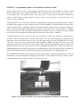
3. Ensure that the blocks holding the car up are secure and car wheels have at least a 1 inch clearance from
the device platform.
4. Do not short any connections on the device. This may result in a fire hazard.
5. Check all connections before the device is turned out.
6. Students should not have access to inner workings of car, unless specified by the instructor.
GOAL
By doing this lab assignment, you will:
1. Learn about the Controller Area Network Interface on the C8051F040 development board
2. Utilize the CAN Transmit and Receive Protocol to communicate with the PIC microcontroller in the R/C car
3. Understand specific applications of CAN in different industries
4. Comprehend CAN Protocols & Hardware
5. Employ NI hardware and LabVIEW software to develop a Graphical User Interface for Data Acquisition and
take advantage of a provided LabVIEW VI program to assist in debugging
PREPARATION
References: C8051F04x.pdf 8051 C8051F04X Reference Manual, Ch. 5, 8, 18, CAN library documentation and
C8051F04x-DK.pdf C8051F04x Development Kit User’s Guide, both found on the MPS web page
Write a C program that is free from syntax errors (i.e., it should assemble without error messages)
REQUIRED MATERIAL
Hardware Requirements
o
o
o
o
Two 8051F040 Development Boards with USB SiLabs MCU Programming Adapters
CAN-Controlled R/C Car (with lights, horn, drive motor, steering servomotor, etc.)
Meter Box with 3 meters and Control Box with switches and potentiometers.
5 Volt DC power supply
LabVIEW Requirements
o
o
CAN-viewer-MPS.vi
CAN-sender-MPS.vi
o
o
o
o
o
o
NI-Tutorial-9759-en.pdf, NI-Tutorial-2862-en.pdf, NI-CAN Channel and Frame API - National
Instruments.pdf, Which NI-CAN Frame API Functions does the NI USB-847x Device Support.pdf
NI CAN Demo Box and USB-8473s or USB-8473 connector(s)
Two computers (laptops) running LabVIEW 8.6, 2010 or 2011
Two Female to Female DB-9 CAN Serial Cables (with terminating resistors - on labeled end)
Two Female to Female DB-9 CAN Serial Cables (without terminating resistors)
CAN bus Cable with multiple DB-9 Connectors (Male and Female)
Controller Area Network Interfaces
Overview
The Controller Area Network (CAN) is a serial bus communications protocol developed by Bosch in the early
1980's and is used as a standard for efficient and reliable communication between different nodes in industrial
applications. One prime application upon which this lab is based is the automotive industry where CAN is used to
send data among different nodes in a car.
Each subsystem, such as the engine controller and the instrument panel, shares a common bus for sending and
receiving messages. To make sure that higher priority messages that would directly affect car performance are
given precedence, a CAN data frame contains a message ID, which doubles as a priority code. Frames with a
higher priority (lower ID) win the message arbitration and continue to send the frame whereas those with lower
priority (higher ID) back off and wait to retry until the channel is clear again.
By sending frames with the appropriate ID within the CAN network one can either send a command or send a
request for data. This lab will require setting up two 8051 development boards on a CAN bus. One board will be a
control module that will transmit data only and the other will be a display module that will receive data from the
car. The IDs of different messages are listed in Appendix A.
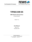
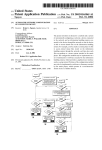
This lab uses a model car that has been set up internally with a CAN controller which receives commands sent to it
over the CAN bus and activates the various devices in the car, such as the horn, headlights, drive motor, etc. Below
is the block diagram of the internal CAN device. For size, cost, and other factors, it uses a PIC18F25K80
microcontroller rather than a C8051F040 microcontroller. None of this makes any difference to the user since the
tasks for the students only involve sending commands over the CAN bus and the details of the controller receiving
the commands are transparent to the user.
Motor
Speed
Control
Servo
Output
LED
Output
(Airbag
Control
Output)
Speed
Input
PIC18F25K80
System
Controller
CAN
Transceiver
and
Interface
Temperature
Input
Current
Sensor
Input
Figure 1: Controller Block Diagram for the Car Chassis Module.
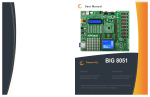
The final system configuration for this exercise will have two C8051F040 processor cards connected to the
common CAN bus of the Car Module as well as several wires and cables connected to the Control Module, and
Meter Module. The block diagram below shows the required electrical connections among the various components
of the exercise.
CAN/USB interface to PC
running NI LabVIEW tools
Figure 2: CAN System Layout Diagram.
In the steps leading up to this final configuration, two intermediate configurations will be used. In PART I, the Car
Chassis will be replaced with a NI CAN Demo Box, the Control Module will be replaced with a LabVIEW VI for
sending commands, and the Meter Module will be replaced with another LabVIEW VI, running on a separate PC,
that will be listing the CAN messages and displaying status using various control panel indicators. PART II will
keep the two LabVIEW VIs for the modules while switching the NI CAN Demo Box back to the Car Chassis.
PROGRAMMING TASKS
The first programming task will be a visual programming assignment to develop a more advanced version of the
LabVIEW CAN bus monitoring VI that displays all the status information available from the car. The second, C
programming, task will require the use of the CAN library that has been provided. Documentation for this library
has been provided in HTML format on the course web pages. To interface the 8051 development boards to the car,
plug into the male DB-9 connectors on the cables going to the car base station. The female DB-9 connector is for
use with a debugging device and will not work with the 8051 development boards. For the CAN baud rate to work
correctly, it will be necessary to configure the C8051F040 to use the external crystal oscillator. See can.c where
the CAN rate is specified as 500kbps using the 22.1184MHz crystal oscillator.
PART I - CAN Basics with LabVIEW & CAN Demo Box
To become familiar with the CAN bus hardware and messages, the first task involves using LabVIEW visual
programs and a National Instruments CAN Demo Box. The programs allow the user to send commands on the
CAN bus and observe them simultaneously using 2 VIs set up on 2 different computers running LabVIEW. Read
the NI_User_Manual file on the MPS web page for details on the procedure to install LabVIEW on your laptop.
The studio desktops have the software installed but it will be extremely helpful and instructive for students to have
their own copies for this exercise.
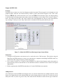
LabVIEW Interface for Program Development
The LabVIEW VIs for the Microprocessor Systems course are designed to send and receive CAN messages to and
from the CAN Demo Box and RC car in the lab. The front panel features a table that displays all of the CAN data
including timestamp, ID, frame type, bytes, and data. There is also the option to filter messages by ID, which is
useful when focusing on one specific function or part of the car. The sending VI allows the user to transmit data on
a specific ID to the car. This is done manually (no control interfaces such as knobs, etc.) and students who are
interested in expanding their LabVIEW skills will be able to expand on this. Start with LabVIEW VIs
CAN Receive.vi and CAN Transmit – event based.vi and then move to the similar versions, but customized,
CAN-viewer-MPS.vi and CAN-sender-MPS.vi. NOTE: the default version of LabVIEW is 11, but 2 older
versions of these VIs are available, with (10) and (8.6) in their file names.
Some numerical conversions may be required for meaningful data in receiving mode. Sending mode does not
require any conversion since the data value is user-defined. This aims to help in the education and understanding
of the entire system since the data range must be understood. All pertinent information can be found in the data
dictionary.
PART II - LabVIEW VI Development and RC Car
This portion of the lab will add the RC car to the CAN bus and control its functions with the LabVIEW VIs CANviewer-MPS.vi and CAN-sender-MPS.vi. All the assigned Arbitration IDs from 1 to 11 can be used to activate
their respective functions or receive respective status information. The exercise in VI development will have
students copy CAN-viewer-MPS.vi to a new file and add new control panel indicators to the new file. The goal is
to create a VI that is able to display all the functions and status available on the RC car.
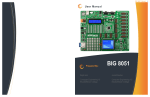
Figure 3: The CAN-sender-MPS.vi front panel for sending CAN commands on the bus.
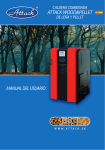
Figure 4: The CAN-viewer-MPS.vi front panel for monitoring and displaying CAN bus information.
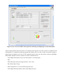
After becoming familiar with both of these VIs and their block diagrams, one of the objectives of PART II is the
development of an enhanced monitoring program that displays the rest of the car data. On possible example is
shown below. In addition to the list of CAN commands passed on the bus and the three indicators (Headlight,
Wheel RPM, and Motor Current), students are asked to add indicators for:
Left & Right Turn Signals (may be activated together as a warning light)
Horn
Wheel Steering Position (from approximately -20° to +20°)
Drive Motor Input Voltage
Motor Temperature in °C (from a Status Reply message)
Left & Right Turn Signal Status (from a Status Reply message)
Figure 5: A typical student-developed front panel for monitoring and displaying all CAN bus information
from the RC car.
Important Notes on the RC Car
All the functions on the car work, however the drive motor may cause some problems. The input voltage must be
above a threshold of ~1.3V before the wheels will turn, and even at that the wheels will need to be kick-started. A
high enough starting voltage will start the wheels without a kick-start. The drive motor is extremely noisy,
electrically, and attempts to reduce the EMI have not been successful. If the motor is left running for more than a
few seconds the EMI may crash the PIC microcontroller. If that happens, the car stops responding to all CAN
commands and must be reset by cycling the 5V power supply. This is inconvenient, but not insurmountable as to
prevent the lab exercise from being completed. Another known issue is with the drive transistor for the inductively
loaded motor. Even with a bypass diode, if the base current to the transistor is turned off too quickly the transistor
will breakdown and pass current even though the transistor should be shut off. The best way to avoid this is to
ramp down the base current slowly (over ~1 second). If the motor still runs when the base current is off you can
always shut off the +5V to the car or bring up the base current again and ramp down more slowly.
The RC car will automatically send a message with ID 8 every few seconds giving the wheel RPM value. This is
the only data sent without a request command. To get the status of the temperature, motor current, and turn signals
a CAN command must be send with the desired ID and the RTR flag set (in the sender VI panel or in the CAN
command function call).
PART III - C Programming: Separate Control Module and Meter Module
In this portion of the lab, write a simple program which will turn on the car’s headlights by sending a CAN
message containing the bytes 0x0001 with ID 0x01. This will require use of the can_init( ), can_get_tx_buf( ),
can_set_address_std( ), can_set_buffer_data( ), can_send_tx_buf( ), and can_send_rtr( ) functions. You may also
wish to test CAN message reception using the can_get_rx_msg( ), can_get_address( ), can_get_data_byte( ), and
can_free_rx_msg( ) functions.
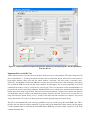
Expand upon the code to read values from the two potentiometers (steering and acceleration) and the switches
(headlights, left & right turn signals, and horn) on the car Control Module. The Control Module is the black box
with two toggle switches, a push-button switch, and two potentiometers, shown in the lower left part of the figure
below. Your code should control the headlights, turn signals, steering, drive motor, and horn on the car. Transmit
these values to the car’s CAN bus using the same functions used in Part I. Please see Appendix A for the CAN IDs
to be used for each controlled item, and appendix B for the pin-out of the control’s connectors.
Using the functions can_init( ), can_get_rx_msg( ), can_get_address( ), and can_get_data_byte( ), develop code for
the 8051 to drive the analog meters and turn signal LEDs. Your code should display the readings from the
temperature, speed, and current sensors as well as the turn signal status. Since the C8051F040 only has 2 D/A
converters, it will be necessary to enable Pulse Width Modulation (PWM) using the 8051’s PCA to drive the
temperature meter. Please see the 8051 reference manual, chapter 24 on the programmable counter array (PCA) for
further information. You may also want to refer to your Embedded Control notes to refresh your memory for
PWM implementation on the 8051. See Appendix A for information on CAN IDs, Appendix B for information on
the pin-out for the meters and more details on all signal wiring and Appendix C for sample program code.
The LabVIEW VI developed for Part I with the features shown in Figure 5 should respond identically to the car
and should be used in development and debugging of the 8051 C code. Compare the messages in the VI viewer
buffer commands sent by the sender VI to those issued by the C code.
Figure 6: Car Control Module Box (lower left) and Analog Meter Module Box (lower right).
The C8051F040 still has a UART0 serial port for printing output or debugging information on a terminal. As in all
MPS labs the port must be configured with a counter to set the BAUD rate. The C8051F040 does not have a PLL
so the crystal oscillator frequencies are greatly limited. After initialization switch to the 22.1184MHz crystal
frequency to reduce confusion and keep the setup option simple.
USAGE GUIDELINES AND INSTRUCTIONS
1. Safety
a. While the voltages used in this project are not dangerous, there may be a danger of damage to the
hardware due to excessive current flow. It is necessary to always connect this device to a power supply
that limits current to a safe level. Unsafe power supplies include devices such as car batteries.
b. Do not short any connectors as damage or fire may result.
c. Always verify that the drive wheels are off the ground before attempting to start the car’s motor. Also
ensure that the front wheels are free to turn.
2. Initial Setup / Components Identification.
a. It is necessary to supply only +5V power and ground to the car unit. Identify the 2 twisted-pair power
cables from the car. It has a red and a black plug, and the red plug is labeled with a voltage. The black plug
corresponds to the ground.
b. There are 3 DB-9 connectors on the CAN bus cable. The two male connectors have the correct pin-out to
interface to the C8051F040 development boards in the lab. The female connector follows OBD-II standard
pin-outs and is suitable for connection to certain other commercially available CAN devices. There are
various CAN cables with both male and female DB-9 connectors as well as splitter and multi-tap cables.
There are enough cable types to handle the worst-case configuration: 2 8051s, the car, and 2 PCs running
LabVIEW all connected on the CAN bus simultaneously. It should be noted that the 2 NI CAN cables with
female DB-9 connecter have terminating resistors on the end with the label. The CAN bus specifications
call for terminating resistors at both far ends of the physical bus. The car also has built-in terminating
resistors.
CAUTION: when attaching several devices to the CAN bus simultaneously make sure the bus isn’t
flooded with commands. The relatively slow bus configuration used here can only handle a limited
number of commands per second.
c. The order of power supply power-up sequencing is unimportant, but it is important to check all power
connections for correct voltage and polarity before turning on power.
3. Use of CAN Interface
a. 11-bit CAN message IDs are used for all communication.
b. The CAN interface on the car will receive messages with several message IDs. (See Appendix A.)
c. The CAN interface on the car transmits several messages with real-time data from sensors. (See Appendix
A.)
d. The C8051F040 development boards need to be plugged into the Control and Meter Modules to correctly
send and receive CAN information. Each 10-pin connector should be placed on the pins such that pin 1 of
the connector aligns with pin 1 of the port (except for the DAC - see 2b in Appendix B). This corresponds
to having the end of the connector with the ribbon on it facing the side that the power to the board comes
in on.
Using LabVIEW 2011
Overview
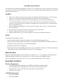
LabVIEW has two main views, the block diagram and the front panel. The front panel can be thought of as the
graphical display where the user interacts directly with the system, and the block diagram as the “code” itself.
Pressing CTRL+E will switch between these two views and CTRL+T will tile them side-by-side. Right-clicking
on the front panel will bring up the menu where controls and indicators can be added. This is shown in Figure 7
below. Also shown are the “Run” and “Abort” buttons in the red highlighted area. Never use the abort button to
stop a running VI. Always use the “Stop” button which is included on the front panel (added by the user).
Figure 7: A Blank LabVIEW Panel Showing the Open Control Menu.
Instructions
1. Configure the NI hardware and software tools to send and receive CAN messages. This includes using the
Demo Box and USB connectors to create a bus connecting two computers both running LabVIEW, the RC car,
and the Demo Box. Study the message format and protocol.
2. Now, connect to the RC car. Using the same LabVIEW VIs, edit the block diagrams and/or front panels to
properly display data received from the car. You should also be able to send data to the car and have it respond
appropriately.
3. Finally, implement this LabVIEW functionality in C for the C8051F040 microcontroller.
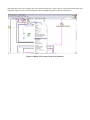
Adding Sensors
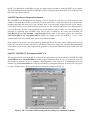
An essential part of the LabVIEW block diagram is the case structure which allows for multiple indicators on the
display to be updated based on the arbitration ID. One of the learning objectives in this lab is to add cases for the
other parts of the car (some are given to start). This means that the ID must be known and the type of indicators
that makes the most sense to display the given data must be chosen. Again, choices can be made based on the data
dictionary. Figure 8 shows the block diagram with the highlighted option to add a new blank case.
Figure 8: Adding A New Sensor in the Case Structure.
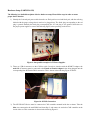
Hardware Setup (PARTS II & III)
The following is a detailed description of device hardware setup. Please follow steps in order to ensure
proper device function.
1) Identify the 2 twisted-pair power cables from the car. Each pair has a red and black pair, with the red being
labeled with the proper voltage that it needs to be plugged into. The black plug corresponding to the red
plug is ground. Similarly the black plug accompanying the +5V red plug is also ground. Secure these to
the proper power supplies as seen in the following figure, before powering on the device.
Figure 9: One possible example of +5V Power Supplies.
2) There are 3 DB-9 connectors on the CAN bus cable. In order to interface with the NI MCU Adapter, the
male DB-9 Connector must be connected to the Female to Female Adapter before being plugged into the
corresponding blue NI Female DB-9 connection. This is shown in the following Figure 10 below.
Figure 10: NI USB Connection.
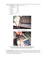
3) The NI USB 8473 Device must be connected to CAN controller mounted inside the car frame. Take the
blue wire connected to the male DB-9 head from Step 2, and connect its end to the CAN controller on the
inside of the car. This connection is shown in the following Figure 11.
Figure 11: NI USB Connection with CAN MCU
4) The 8051 development boards need to be plugged into the control and meter box modules to ensure the
proper delivery and receiving of CAN information. Each 10-pin connector from the modules should be
plugged in such that Pin #1 aligns with the corresponding Pin #1 on the port of the MCU. If this has been
plugged in correctly, the ribbon should be facing towards the power connection of the board. The red
stripe indicates pin 1 on the left side. This correct configuration is shown in the following Figure 12.
Figure 12: 8051 Power Connection and Control Module ribbon cable Plugged In
5) The Control module has 3 wires and one 10-pin connector. The black wire should be attached to analog
ground (J20-8) and the red and green wires are to be attached to the ADC outputs (J20-6 & J20-5
respectively). These values read in from the two potentiometers are specifically used for steering and
speed. This example uses P3 but users may choose to use a different port. The 10 pin connector (on P3)
reads in values as follows (all are active low logic signals):
1. Headlights
(P3.0)
2. Right turn signal (P3.1)
3. Left turn signal
(P3.2)
4. Buzzer
(P3.3)
5. Not Used
(P3.4)
6. Not Used
(P3.5)
7. Not Used
(P3.6)
8. Not Used
(P3.7)
9. Port power (+3.3V)
10. Ground
Figure 13: Control Module
Figure 14: Control Module Connection with C8051 Development Board.
(Note that the ribbon cable is attached to P1 instead of P3 here.)
6) The Meter module has 1 output wire and 2 10-pin connectors. The one wire is for ground and should be
attached to the analog ground. The two 10-pin connectors differ by how bright the red stripes on them are.
This example uses P0 but users may choose to use a different port. The cable with the darker red stripe is
for the Port pins and has the following pin-out:
1.
2.
3.
4.
5.
6.
7.
8.
9.
10.
Not Used (UART0 TX)
Not Used (UART0 RX)
Temperature (PWM signal)
Not Used
Turn left signal
Turn right signal
Not Used
Not Used
Port power (+3.3V)
Ground
(P0.0)
(P0.1)
(P0.2)
(P0.3)
(P0.4 & low active logic signal)
(P0.5 & low active logic signal)
(P0.6)
(P0.7)
The cable with the dashed red stripe is for the DAC outputs. Only the middle two pins are used (J11-3 & 4). These
are for DAC0 and DAC1 respectively. Therefore the 10-pin connector should be placed on the 6 pins of the DAC
output (J11, see development board manual) such that the 6 pins are centered in the connector (pins 1 & 2 and 9 &
10 on the cable are unconnected).
Figure 15: C8051 Connection with R/C Car
7) If necessary, and with a TA present, check to ensure the 2 - LED lights on the plastic car case are
connected and secured to the CAN Network board. Ideally these should not be removed. The wires are
shown in the following Figure 16.
Figure 16: LED Head/Tail Light Connections
8) After All Modules have been connected properly, place the large plastic cover over the inner parts of the
car. The plastic cover should ideally be screwed on to discourage the students from tampering with the
inner workings.
Figure 17: RC Car Cover
The following is a complete Wired Block Diagram for the CAN System. It includes the National Instruments USB
8473 Connection Device that is detailed in the NI Hardware Manual.
Figure 18: Wiring Block Diagram
APPENDIX A: CAN Addresses
Full documentation is available on the web at: http://www.rpi.edu/dept/ecse/mps/mps_handouts.html
The CAN interface on the car will receive messages with several message IDs:
0x01: Headlights. This message should contain 2 data bytes. These data bytes represent the desired state of the
headlights on the car. 0x0000 turns the headlights off, and any non-zero value turns them on.
0x02: Left Turn Signal. The format of this message is identical to that for 0x01: Headlights. When this feature
is activated, the left front and rear signal lights will blink at a frequency of approximately 1 Hz.
0x03: Right Turn Signal. The format of this message is identical to that for 0x01: Headlights. When this
feature is activated, the right front and rear signal lights will blink at a frequency of approximately 1 Hz.
0x04: Horn. This message should contain 2 data bytes. If these data bytes are non-zero, the horn will begin to
sound. If 0x0000 is received, the horn will stop sounding.
0x05: Motor Speed. This message should contain 2 data bytes with a value between 0 and 4095. [The first data
byte represents the motor power as a value from 0x00 (0) to 0xff (maximum power.) The second data byte
represents the motor direction. 0x00 represents forward and 0x01 represents reverse.] In the current
hardware, reverse is not implemented and can’t be used.
0x06: Steering Position. This message should contain 2 data bytes. These bytes represent the pulse width (in
10-us units) that will be sent to the steering servo. This value should vary between 0x352 (850) and 0x866
(2150), with the servo center position being at 0x5DC (1500). Inputting values outside the valid range will
result in undefined behavior and may damage the hardware.
The CAN interface on the car transmits several messages with real-time data from sensors (RTR set high):
0x07: Motor Temperature. This transmits the temperature sensor output voltage as a value on a linear scale
from 0 (-50 °C) to 1758 (150 °C); 50 °C => 910.
0x08: Speed. This transmits the rotational speed of the wheel in counts/second. The sensor counts twice per
wheel rotation so actual rotations per second is this value divided by 2. (There is a delay in outputting this
value as the processor averages over a short time period.)
0x09: Motor Current. This transmits the current flow measured through the motor, as a value on a linear scale
from 0 (0 mA) to 4095 (~1023 mA). The motor current is extremely noisy and this is only a reasonable
approximation to the true value.
0x0A: Left Turn Signal. This outputs the state of the left turn signal (0x00 for off and 0xFF for on.)
0x0B: Right Turn Signal. This outputs the state of the right turn signal (0x00 for off and 0xFF for on.)
Table 1: Car Controller Command Functions (& specifications for potentiometers outputs)
Function
Message ID
Data
Headlights
0x01
2 bytes: 0=Off 1=On
Left Turn Signal
0x02
2 bytes: 0=Off 1=On
Right Turn Signal
0x03
2 bytes: 0=Off 1=On
Horn
0x04
2 bytes: 0=Off 1=On
Drive Motor
0x05
2 bytes: 0 - 4095
Steering Servo Motor
0x06
2 bytes: 0 – 4095 but must be mapped
to range: 850 (fully right) - 2150 (fully left)
Table 2: Car Meter Monitor Functions (specifications for analog meters)
Function
Message ID
Data Format
Temperature
0x07
2 bytes: ADC Reading 0 – 4095
(50 °C => 910)
Rotational Speed (RPM)
0x08
2 bytes: 0 - ~700
Motor Current draw
0x09
2 bytes: PIC ADC Reading 0 – 4095
(Imotor (mA) ≈ PIC ADC Reading/4)
Left Turn Signal
0x0A
1 byte: 0=Off 0xFF=On
Right Turn Signal
0x0B
1 byte: 0=Off 0xFF=On
With the internal 2.4V reference voltage (the only value used here for convenience and to reduce the chance of
accidentally destroying equipment and EVB boards):
Make sure the correct jumpers are on J22 VREF pins on the EVB.
The analog MPH meter goes from 0 to 48 MPH with an analog input voltage from 0V to ~2.4V (= 4095). A good
scaling to get MPH is to multiply the RPM value by 6.7. This is an arbitrary constant to give a meter reading
that spans the range of the meter and provides a value that can be loaded directly into the DAC input registers.
The analog Motor current meter goes from 0 to ~0.850A with an analog input voltage from 0V to ~2.4V (= 4095).
With a PWM signal driving the Temperature meter, 0% - 100% duty cycle will drive the meter from 0 to ~48°C.
When setting the analog MUX channel for 12-bit ADC0 conversions a small delay is required between when the
channel is selected and when conversion is started. The capacitance of the track and hold circuit requires
somewhat less than a millisecond to achieve steady state with the switched input voltage.
Known PIC Issues:
Sending the values 1141 or 1142 in the steering command (CAN ID = 6) causes the steering servo to thrash past
the leftmost limit. Until this is corrected on the PIC microcontroller please avoid sending these values or at
least send any legal value immediately afterwards.
If the RPM value stops working it may be due to the reed relay sticking closed. Tapping the relay behind the
left drive wheel may release the stuck contacts.
APPENDIX B: Module Pin-outs & Signal Scaling
The C8051F040 development boards need to be plugged into the Control and Meter Modules to correctly send and
receive CAN information. Each 10-pin connector should be placed on the pins such that pin 1 of the connector
aligns with pin 1 of the port (except for the DAC, see 2b below. This corresponds to having the end of the
connector with the ribbon on it facing the side that the power to the board comes in on.
1. The Control Module has three wires and one 10-pin connector.
a. The three separate wires connect to J20:
J20-5 ADC0 input AIN0.0
Green wire from Motor Drive pot
J20-6 ADC0 input AIN0.1
Red wire from Steering pot
J20-8 Analog Ground
Black wire
b. The ribbon connector may be attached to any port 1 – 7. You just must keep track of which port is used
when developing the control module software. Pins 1-4 must all be configured as inputs with open-drains
and weak pullups (XBR2.7 = 0). The 10-pin connector reads in values to the C8051F040 as follows:
1. Headlights
2. Right turn signal
3. Left turn signal
4. Buzzer (Horn)
5. Not Used
6. Not Used
7. Not Used
8. Not Used
9. Port Power (+3.3V)
10. Ground
The potentiometers output 0 – 3.3V. With the internal 2.4V reference voltage on the 12-bit channels conversion
values are 0 – 4095 (with the last ~25% of the turn saturating after the voltage rises above 2.4V). The CAN Motor
command accepts a value from 0 – 4095 but the useable range where the motor reacts is ~2300 - ~3075. The can
Steering command value must be in the range from 850 – 2150 and the software must insure the value form the pot
voltage is correctly mapped into this range to prevent damaging the servomotor.
2. The Meter Module has one output wire and two 10-pin connectors. The single wire is for ground and should be
attached to the analog ground screw terminal on the EVB (J20-8). The two 10-pin connectors differ by the
appearance of the red stripes on them.
a. The cable with the solid red stripe is for the port pins and may be attached to any port 0 – 7. You just must
keep track of which port is used when developing the meter module software. Pins 3, 5 & 6 must be
configured as outputs with Push-Pull. The10-pin ribbon cable’s pin-outs from the C8051F040 are wired as
follows:
1. Not Used
2. Not Used
3. Temperature (PWM signal)
4. Not Used
5. Turn left signal indicator (active low)
6. Turn right signal indicator (active low)
7. Not Used
8. Not Used
9. Port Power (+3.3V)
10. Ground
b. The cable with the dashed red stripe is for the DAC outputs. Only the middle two pins are used (J11-3 &
4). These are for DAC0 and DAC1 respectively. Therefore the 10-pin connector should be placed on the 6
pins of the DAC output (J11, see development board manual) such that the 6 pins are centered in the
connector (pins 1 & 2 and 9 & 10 on the cable are unconnected).
APPENDIX C: Pseudo-Programming Example
/*
* Note that these examples do not include everything necessary for fully
* working CAN. It is necessary to set up the crossbar and system clock
* correctly in order for the CAN module to work properly.
* If terminal printing is desired UART0 with a timer for BAUD rate is needed.
*/
/* Example CAN Transmission Code */
/* This will send a 3-byte message (0x12 0x34 0x56) to 10-bit address 0x123 */
#include "can.h"
/* ... */
unsigned char data[3] = {0x12, 0x34, 0x56};
CAN_BUFFER canbuf;
can_init( );
/* ... */
while (1) {
/* ... */
if (want_to_transmit_something) {
canbuf = can_get_tx_buf( );
can_set_address_std(canbuf, 0x123);
//CAN message ID = 123
can_set_buffer_data(canbuf, data, sizeof(data));
can_send_tx_buf(canbuf);
}
/* ... */
}
/* Example CAN Reception Code */
/* This will receive a message and print its contents to the terminal */
/* Might also be useful for testing purposes */
#include "can.h"
/* ... */
unsigned char data[8];
CAN_BUFFER canbuf;
can_init( );
/* ... */
while (1) {
/* ... */
canbuf = can_get_rx_msg( );
// check if anything was actually received
if (canbuf) {
printf("Length: %d\n", can_get_dlc(canbuf));
printf("Message ID: %04x\n", can_get_address(canbuf));
printf("Data: ");
for (i = 0; i < can_get_dlc(canbuf); ++i) {
printf("%02x ", can_get_data_byte(canbuf, i));
}
printf("\nEnd of Message\n");
}
}
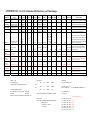
APPENDIX D: RC Car CAN Arbitration IDs, Functions, and Value Ranges
!"#$%"&'()"
C"(J5$4?9E
>"K&6+I,&3$4,(5
<$4?9&6+I,&3$4,(5
C.I,
21/&&&&&&& !(9(& 3()85$,4& =79"&
*+,%-.,
<(9"
>",49? !(9(978"
/0'&1! 3$4,(5&678" 6:;<:
!"#$%&'(%'()*+,-'&.%/$%
2"&3"&%%%%%
/#%/0
1
4,-%5/+&)-(
67
8 922:
E)F(.%G#/$&%)$*%#()#%
2"&3"&%%%%%
+(H%+,-'&%I+,$F%)&%1%J@
8
4,-%5/+&)-(
67
8 922:
E)F(.%G#/$&%)$*%#()#%
2"&3"&%%%%%
#,-'&%+,-'&%I+,$F%)&%1%J@
K
4,-%5/+&)-(
67
8 922:
!"#$.%'/#$%LI"@@(#M%/$%
2"&3"&%%%%%
/#%/0
N
4,-%5/+&)-(
67
8 922:
!I$#"&G.9.I
O/$&#/+.%E/&/#%P3((*%
LQRS%)$*%4,#(CD/$M
39""I$,4&3"I#.
O/$&#/+.%P&((#,$-%
R/.,D/$
LL&3606F3&LL&
2"&3"&.%E/&/#%
6")8"I(9+I"&3",E.I !(T3(#)&"#(
LL&3606F3&LL&&&&&&
M?""5&38""J
2"&3"&.%6/&)D/$)+%
P3((*%/G%['((+
LL&3606F3&LL&&&&&&
/+II",9&3",E.I
LL&3606F3&LL&&&&&&&&
>"K&6+I,&3$4,(5
LL&3606F3&LL&&&&&&&
<$4?9&6+I,&3$4,(5
A<"E"I#"JB
2"&3"&.%E/&/#%O"##($&
2"&3"&.%.&)&(%/G%+(H%
&"#$%.,-$)+
2"&3"&.%.&)&(%/G%#,-'&%
&"#$%.,-$)+
<
Z
Y
X
_
2"&3"&%
>$)+/-%
5/+&)-(
2"&3"&%
R[E%
5/+&)-(
Q$3"&%
>$)+/-%
5/+&)-(
Q$3"&%4,-%
R"+.(.
Q$3"&%
>$)+/-%
5/+&)-(
67
8 Q$&(-(#
67
8 Q$&(-(#
!7^67
8 Q$&(-(#
<(,4"&>.@&
A0,(5.4B
<(,4"&C$4?&
A0,(5.4B
1;D&<(,4"&
1;D&<(,4"& !$E85(7&<(,4"& !$E85(7&<(,4"&
>.@&A!$4$9(5B C$4?&A!$4$9(5B
>.@
C$4?
!$E85(7&F,$9E
G$E%&1,H.I)(-.,
2"&3"&%;5
2"&3"&%<5
;
1
20
2$
=
>$?%$/$=@(#/%A)+"(%B,++%)CDA)&(%&'(%'()*+,-'&.
2"&3"&%;5
2"&3"&%<5
;
1
20
2$
=
>$?%$/$=@(#/%A)+"(%B,++%)CDA)&(%&'(%&"#$%.,-$)+
2"&3"&%;5
2"&3"&%<5
;
1
20
2$
=
>$?%$/$=@(#/%A)+"(%B,++%)CDA)&(%&'(%&"#$%.,-$)+
2"&3"&%;5
2"&3"&%<5
1
20
2$
=
>$?%$/$=@(#/%A)+"(%B,++%)CDA)&(%&'(%'/#$
2"&3"&%;5
;
E,$,T"T%
A)+"(%&/%*#,A(%
T/&/#%U8;<;%
LE)?%$((*%&/%
F,CF=.&)#&%
B'((+.M%
2"&3"&%<5
;7;;;;
2"&3"&%R[E% 2"&3"&%R[E%
;5
<5
Q$3"&%;W<5
Q$3"&%NW<5
!'(%8%*)&)%I?&(.%#(3#(.($&.%&'(%T/&/#%3/B(#%
X<;
81<;
).%)%A)+"(%G#/T%;7;;%&/%;7Y0W%!'(%EP9%L811%I,&M%
#(3#(.($&.%&'(%T/&/#%*,#(CD/$%;%#(3#(.($&.%
G/#B)#*%)$*%1%#(3#(.($&.%#(A(#.(W%6(A(#.(%B,++%
;5
U1WX5
$/&%I(%".(*%,$%&',.%+)I%LB/#F%QRMW
5)+"(%B,++%A)#?%G#/T%X<;%L#,-'&M%)$*%81<;%L+(HM%
B,&'%&'(%.(#A/%C($&(#%3/.,D/$%)&%1<;;W%RQO%
R"+.(%B,*&'%,$% ./HB)#(%/$%C)#%B,++%+,T,&%#)$-(%&/%3#(A($&%
\8;]%%%%%%%%%%%%%%%%%%%% =8;] 1;%".%"$,&. *)T)-,$-%')#*B)#(W
;
N;_<
;%L;M
;7;VVV
N;;%LN;_<M
4(-#((.%O
P($./#%C/"$&.%&B,C(%3(#%#/&)D/$`%./%)C&")+%
#/&)D/$.%3(#%.(C/$*%,.%&',.%A)+"(%*,A,*(*%I?%8W%%
Y;; C/"$&.^.(C/$* 6RE%T)?%I(%".(*%,$.&()*W
!7^67
8 Q$&(-(#
Q$3"&%;5
Q$3"&%<5
=K8YZX
K8YZY
;
!7^67
8 Q$&(-(#
%Q$3"&%;5
Q$3"&%NW<5
;
N;_<
;%L;M
1;8K%LN;_<M
T,++,>T3.
1;
= !7^67
1 922:
=
=
;
;7VV
20
2$
=
;7;;%G/#%/0%)$*%;7VV%G/#%/$
11
18
= !7^67
1 922:
=
=
;
;7VV
20
2$
=
;7;;%G/#%/0%)$*%;7VV%G/#%/$
6RES%;%=a%\Y;;
1Z=I,&%.,-$(*%,$&(-(#
/"&3"&%&/%T(&(#%C+,33(*%&/%I(&B(($%;%d%\Y;;
P&((#,$-%P(#A/
X<;
\8;]
;7K<8
6QbJ!
1<;;
;]
;7<4O
Oef!e6
81<;
=8;]
;7XZZ
:eV!
Z<;
Z<;
4#,A(%E/&/#%LA/+&)-(.%/"&%/G%RQOM
E,$S%U81;;%LT)?%$((*%&/%F,CF=.&)#&%B'((+M U1WK5%L8W<5M
E)7S%N;_<
8WN5%LNWX5M
RQO%4>O%/"&3"&%7%;W<%&/%E/&/#%4#,A(%,$3"&%L)g($")D/$%c%;W<M
!(T3(#)&"#(
;]O%=a%;W<5%\%;W;15^]O%c%;W<5
)$-+(%L]M%c%Lf=1<;;ML=8;M^Z<;%c%=;W;K;YZ_8f%\%NZW1<KX<
E/&/#%O"##($&
C"##($&%LT>M%c%fLNW<^N;_ZML1^NNML1^;W1/'TML1;;;M%c%f^N
23>T3%-),$%cNN
O"##($&%.($.(%6%c%;W1%/'T
T>%c%1;;;%>
8;]O%=a%;W<5%\%;W85%c%;WY5
L;WY^NW<M%7%N;_Z%c%ZKY
5%c%fLNW<ML1;;M^N;_Z%c%;W1;_XZKK%7%f
]O%c%;W1;_XZKK%7%f%=%<;
]O%c%1;;%7%5%=%<;
h!'(/#(DC)+%C/$A(#.,/$%A)+"(i
;W;5%c%;7;1;%c%1Z%LU;M%ca%=<;]O
;WY5%c%;78_X%c%%%ZZN%ca%8;]O hZKYi
1W<5%c%;7<Ne%c%1K<X%ca%1;;]O h1KZ<i
8W;5%c%;7Z4e%c%1Y<X%ca%1<;]O h1X8;i
8W<5%c%;7X9V%c%88K_%ca%8;;]O h88YZi
KW;5%c%;7>O9%c%8YZK%ca%8<;]O [2731]
NW;5%c%;7eNV%c%KZZK%ca%K<;]O [3641]