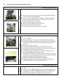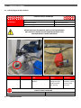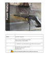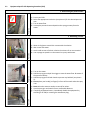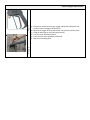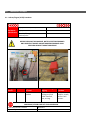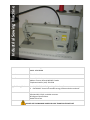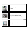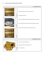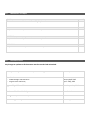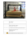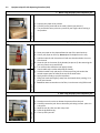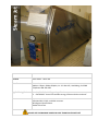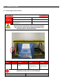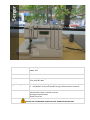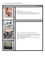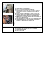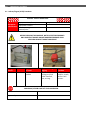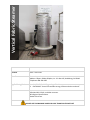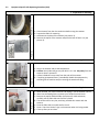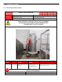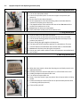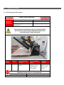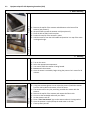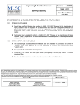
1
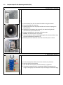
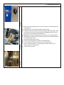
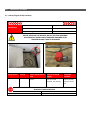
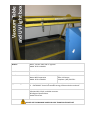
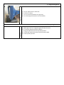
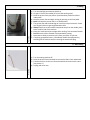
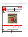
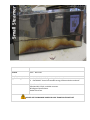
Studio Equipment Safe Operating Procedures Fibre Studio Office of Safety & Risk Management Rosalie Sharpe Pavilion 115 McCaul Room 2210 Paper Beater Machine Paper Beater Location Fibre Studio - Room 201 Manufacturer David Reina Designs Address: 78 Guernsey St. Broklyn Ny 11222 Telephone Number: (718) 486-0262 Applicable Legislation 1. CAN/CSA-Z432-04 “Safeguarding of Machinery” 2. CSA Z460-05 “Control of hazardous energy-lockout and other methods” Sources Manufacturer’s Manual Safe Work BC, CCOHS, and IAPA resources REA Engineer Specifications Studio Technicians DO NOT USE THIS MACHINE UNLESS YOU ARE TRAINED IN ITS SAFE USE! 1.0 Personal Protective Equipment (PPE) Requirements PERSONAL PROTECTIVE EQUIPMENT (PPE) REQUIRED RECOMMENDED Face Shield / Safety Glasses with side shields Dust Mask Respirator Ear Plugs / Ear Muffs ✔ ✔ Gloves Closed-Toe Foot Wear (no heels) Lab Coat / Protective Apron Other ALWAYS WEAR THE REQUIRED PPE WHEN USING THIS MACHINE! ✔ 2.0 Pre-use Inspection Checklist Check 1 Is the power cord free of frays and damage? 2 Is the paper beater in secure place? 3 Is the area around the paper beater free of slip/trip hazards? 4 Is the safety cover and splash guard in place? 5 Has the pulp from previous operation been removed? 6 Does the crank handle move freely without obstruction? Y N N/A Comments/Corrective Action: 3.0 Safe Operating Procedure (SOP) This procedure is outlined as follows: General Safety Guidelines Equipment Specific Safety Operating Procedure 3.1 General Safety Guidelines Before using the machine, perform the following general safety checks: a) Make sure you understand all of the instructional material before operating this equipment. Failure to follow safety instruction and warnings may result in serious personal injury, fire or property damage. b) If you have any questions or uncertainties, please ask your studio technician before use. c) Long hair, scarves, loose clothing, jewellery and ties pose an entanglement hazard. Please make sure these are all constrained prior to operating the equipment. d) Do not conduct any maintenance or repairs on this equipment. In case of a defect, contact your technician. e) Do not remove or render machine guarding ineffective in any way. f) Ensure the work area is both well-lit and organized. Equipment Specific Safe Operating Procedure (SOP) a) Set the count revolution at zero (the point at which the beater roll blade comes into contact with the bedplate). b) Lower the beater roll blade (picture 1) height by turning the handle (see picture 2) counter clockwise and at the same time turn the beater roll blade by hand until you feel resistance. c) Do not rub your hands against the blade. d) Plug in the beater and fill it about 2/3 with water. e) Place the water bucket under the beater. f) Set the beater to 30 complete revolutions of the crank. Picture 2 Picture 1 1. Before using the paper beater Picture 4 Picture 3 2. Using the paper beater a) Turn on the beater. b) While it is operating, with the water circulating, feed in the pulp slowly. c) Feed the beater from the side of the beater opposite the roller (see picture 3). This will keep your hands away from the intake side of the roll (see picture 4). d) Let the water and pulp circulate. e) Turn down the beater roll blade closer to the bedplate as needed f) When necessary add water to the beater to maintain efficient water level. g) Let the beater run for desired amount of time. h) If you need to remove excessive water or pulp from the beater. Do this with a bucket; do not scoop it with your hands. i) If the flow of water and pulp slows down or stops, do not place your hand in the beater. Instead, unplug the machine, and raise the beater roll blade away from the bedplate to free up the jammed pulp. j) Do not leave the beater unattended when in operation. k) If anything unexpected occurs, immediately disable the equipment by switching it off and/or removing the attachment plug. 3. After using the paper beater Picture 5 3.2 a) Once the beating is finished, raise the roll blade back up to about 30 cranks. b) Turn off the motor. Always unplug the beater when cleaning the beater. c) Thoroughly clean the beater. Do not clean the beater roll blade with your bare hands as you might cut yourself. Flush it with stream of water. d) Empty the tub and make sure the bedplate area is free of pulp. 4.0 Maintenance and Repair 4.1. Lockout/Tagout (LOTO) Procedure: LOCKOUT TAGOUT PROCEDURE Equipment Identification Equipment Name/Description: Paper Beater Equipment Location: Fibre Studio Room 201 Total # of Energy Isolation Devices/locks: 1 BEFORE SERVICING THIS MACHINE, NOTIFY AFFECTED PERSONNEL. ONLY PROPERLY TRAINED AND AUTHORIZED PERSONNEL SHALL PERFORM LOCKOUT TAGOUT PROCEDURE Energy Source Location Electrical End of cord Type of EID/lock to be used Plastic clamshell and padlock Steps for locking & tagging Stop machine, unplug cord, and install clamshell, lock, and tag. Verification Procedure Attempt to start machine, visually confirm it will not start. IF SYSTEM CANNOT BE LOCKED OUT OR IF SYSTEM FAILS VERIFICATION PROCEDURE, STOP & CONTACT YOUR SUPERVISOR LOTO Procedure # A-xxxxxxx Revision #: Approved by: Date: 4.2 Inspection Checklist DAILY Ensure the area around the paper beater is free of slip/trip hazards. ✔ Ensure the paper beater is in a secure place. Ensure the splash guard and safety cover is in place and cannot be removed. Inspect the beater roll blade for any defects. Ensure dried pulp is removed from the machine. Ensure the beater roll blade is kept clean. Ensure the crank handle rotates freely. Ensure the roll blade and the bedplate moves freely. Inspect the cord, plug and the motor of the machine. WEEKLY Check all elements of the paper beater. ✔ MONTHLY ✔ Lubricate the crank adjustment shafts. Inspect the beater roll blades to determine their sharpness. ANNUALLY Check the motor of the machine (replace the drive belt if necessary). 5.0 ✔ Document Control Any changes or updates to this document must be recorded and maintained. Initially Created By: The Office of Safety and Risk Management Date: September 2011 Consultation: Studio Managers and Technicians Program Chairs and faculty Date: January-April 2013 April – May, 2013 Approval By: VPFA and VPA Date: September, 2013 Review and Revisions Made By: Date Revised: Changes Made(indicate sections): Revisions Approved By: Date of Approval: Power Washer Machine Electric Powered Pressure Washer Location Fibre Studio – Room 201 Manufacturer Name: Princess Auto Ltd. Address: 481 Panet road, Winnipeg Manitoba Telephone Number: (1800)-665-8685 Applicable Legislation 1. CAN/CSA-Z432-04 Safeguarding of Machinery 2. CSA Z460-05 “Control of hazardous energy-lockout and other methods” Sources Manufacturer’s Manual Safe Work BC, CCOHS, and IAPA resources REA Engineer Specifications Studio Technicians DO NOT USE THIS MACHINE UNLESS YOU ARE TRAINED IN ITS SAFE USE! 1.0 Personal Protective Equipment (PPE) Requirements PERSONAL PROTECTIVE EQUIPMENT (PPE) REQUIRED RECOMMENDED ✔ Face Shield / Safety Glasses with side shields Dust Mask Respirator Ear Plugs / Ear Muffs ✔ Gloves ✔ ✔ Closed-Toe Foot Wear (no heels) ✔ Lab Coat / Protective Apron Other ALWAYS WEAR THE REQUIRED PPE WHEN USING THIS MACHINE! 2.0 Pre-use Inspection Checklist Check 1 Are the power cords free of frays and damage? 2 Is the area around the power washer free of slip/trip hazards? 3 Does the release trigger move freely without obstruction? Y N N/A Comments/Corrective Action: 3.0 Safe Operating Procedure (SOP) This procedure is outlined as follows: General Safety Guidelines Equipment Specific Safety Operating Procedure 3.1 General Safety Guidelines Before using the machine, perform the following general safety checks: a) Make sure you understand all of the instructional material before operating this equipment. Failure to follow safety instruction and warnings may result in serious personal injury, fire or property damage. b) If you have any questions or uncertainties, please ask your studio technician before use. c) Long hair, scarves, loose clothing, jewellery and ties pose an entanglement hazard. Please make sure these are all constrained prior to operating the equipment. d) Do not conduct any maintenance or repairs on this equipment. In case of a defect, contact your technician. e) Do not remove or render machine guarding ineffective in any way. f) Ensure the work area is both well-lit and organized. Equipment Specific Safe Operating Procedure (SOP) Picture 1 1. Before using the power washer a) Put on your PPEs b) Select the appropriate nozzle size (see picture 1) for the desired pressure rate. c) Turn on water flow d) Unwrap the pressure hose and position the spray gun away from the motor. Picture 3 Picture 2 2. Reclaiming a screen Picture 4 3.2 a) b) c) d) Wear nitrile gloves to avoid skin contact with the solution. Wet screen with water. Apply small amount of reclaim solution (see picture 2) on your material. Use a sponge to spread it on the material or spray it with water. a) Turn on the motor. b) Hold the spray gun and pull the trigger to start the water flow. Be aware of the pressure velocity. c) Hold the spray gun with both hands to prevent any backlash (see picture 3). d) Do not place your hand(s) or finger(s) in front of the nozzle when the spray is on. e) Never point the pressure washer at yourself or others. f) Aim the spray gun at the work from a comfortable distance. g) If anything unexpected occurs, immediately disable the equipment by switching it off and/or removing the attachment plug. Picture 6 Picture 5 3. After using the Power washer a) Once done, release the spray gun trigger and flip the safety latch into position under the trigger (see picture 5). b) Squeeze the trigger to allow all the water out from the pressure valve. c) Hang the water gun on the hook (see picture 6). d) Turn the motor off when finished. e) Clean the area upon completion of the task. f) Mop the surrounding floor. 4.0 Maintenance and Repair 4.1. Lockout/Tagout (LOTO) Procedure: LOCKOUT TAGOUT PROCEDURE Equipment Identification Equipment Name/Description: Power Washer Equipment Location: Fibre Studio Room 201d Total # of Energy Isolation Devices/locks: 1 BEFORE SERVICING THIS MACHINE, NOTIFY AFFECTED PERSONNEL. ONLY PROPERLY TRAINED AND AUTHORIZED PERSONNEL SHALL PERFORM LOCKOUT TAGOUT PROCEDURE Energy Source Electrical Location End of cord Type of EID/lock to be used Plastic clamshell and padlock Steps for locking & tagging Stop machine, unplug cord, and install clamshell, lock, and tag. Verification Procedure Attempt to start machine, visually confirm it will not start. IF SYSTEM CANNOT BE LOCKED OUT OR IF SYSTEM FAILS VERIFICATION PROCEDURE, STOP & CONTACT YOUR SUPERVISOR LOTO Procedure # A-xxxxxxx Revision #: Approved by: Date: 4.2 Inspection Checklist DAILY Ensure the area around the power washer is free of slip/trip hazards. ✔ Ensure the power washer motor is sitting firmly on a level base. Ensure water supply is adequate. Ensure the release trigger moves freely without obstruction. Check that the nozzle on the spray gun is not clogged. Inspect the water hose to ensure that it is in good condition. Inspect the water shut-off switch. Check that the pump oil level is within operating range. Add oil if necessary. Check all hardware and replace any damaged or worn components. WEEKLY ✔ Check pressure valve for any wear and damage. Check water inlet filter. When necessary remove residual water from the inlet of the gun. Check the motor and the pump to see if they are in good working condition. Inspect electrical enclosure, cables, and wiring properly. MONTHLY ✔ Check the hose and valves for any leaks. Check the power washer for any rust buildup. ANNUALLY Inspect the entire hardware of the machine to ensure that it runs smoothly. Service as required. 5.0 Document Control Any changes or updates to this document must be recorded and maintained. Initially Created By: The Office of Safety and Risk Management Date: September 2011 Consultation: Studio Managers and Technicians Program Chairs and faculty Date: January-April 2013 April – May, 2013 Approval By: VPFA and VPA Date: September, 2013 Review and Revisions Made By: Date Revised: Changes Made(indicate sections): Revisions Approved By: Date of Approval: ✔ Industrial Sewing Machine Machine Industrial Sewing Machine Model: MSK-8900M Location Fibre Studio – 201 Manufacturer Name: Reliable Corporation Address: Toronto, Ontario M6B 4K7 Canada Telephone Number: (416) -785-0200 Applicable Legislation 1. CAN/CSA-Z432-04 “Safeguarding of Machinery” 2. CSA Z460-05 “Control of hazardous energy-lockout and other methods” Sources Manufacturer’s Manual Safe Work BC, CCOHS, and IAPA resources REA Engineer Specifications Studio Technicians DO NOT USE THIS MACHINE UNLESS YOU ARE TRAINED IN ITS SAFE USE! 1.0 Personal Protective Equipment (PPE) Requirements PERSONAL PROTECTIVE EQUIPMENT (PPE) Face Shield / Safety Glasses with side shields REQUIRED RECOMMENDED ✔ Dust Mask Respirator Ear Plugs / Ear Muffs Gloves Closed-Toe Foot Wear (no heels) ✔ Lab Coat / Protective Apron Other: Thimble ✔ ALWAYS WEAR THE REQUIRED PPE WHEN USING THIS MACHINE! 2.0 Pre-use Inspection Checklist Check 1 Is the area around the industrial sewing machine free of slip/trip hazards? 2 Has the debris/material from previous operations been removed? 3 Is the needle free of defects? 4 Is the bobbin securely in place? 5 Does the foot pedal move freely without obstruction? 6 Does the light bulb/switch work? Y N N/A Comments/Corrective Action: 3.0 Safe Operating Procedure (SOP) This procedure is outlined as follows: General Safety Guidelines Equipment Specific Safety Operating Procedure 3.1 General Safety Guidelines Before using the machine, perform the following general safety checks: a) Make sure you understand all of the instructional material before operating this equipment. Failure to follow safety instruction and warnings may result in serious personal injury, fire or property damage. b) If you have any questions or uncertainties, please ask your studio technician before use. c) Long hair, scarves, loose clothing, jewellery and ties pose an entanglement hazard. Please make sure these are all constrained prior to operating the equipment. d) Make sure the cord is kept away from heat, oil, sharp edges or moving parts and does not pose a trip hazard. e) Do not conduct any maintenance or repairs on this equipment. In case of a defect, contact your technician. f) Do not remove or render machine guarding ineffective in any way. g) Ensure the work area is both well-lit and organized. Equipment Specific Safe Operating Procedure (SOP) 1. Inserting needle Picture 1 a) Put on your PPEs b) Ensure the machine is off. c) check needle 2. Bobbin Picture 2 a) Install the bobbin (see picture 2) from the bobbin case. b) Run the machine to wind the thread on the bobbin. c) Keep your fingers away from the needle when winding the bobbin. 3. Threading Picture 3 3.2 a) Place the thread spool on the spool pin (see picture 3). b) refer to supplied manual for detailed threading instructions a) b) c) d) e) Turn on the machine; the switch is located under the table (see picture 4). Raise the presser foot (see picture 5) and slide the fabric underneath. Never sew with the presser foot in a raised position. Drop the presser foot and begin sewing by pressing on the foot pedal. The presser foot and the feed-dog can cause a pinch point hazard. Ensure your finger(s) does not get caught between them. f) Always keep eyes on the needle. Keep hands away from the needle; place them at either side of the machine. g) Keep your hands and wrists straight while working. Take occasional breaks. h) Industrial sewing machine speed is very fast. Practice running few scraps of material to become familiar with the speed. i) Keep your face at a distance to avoid hitting the take-up lever guard (see picture 6) j) Remember to always remove the pins from your fabric as you sew. k) If anything unexpected occurs, immediately disable the equipment by switching off the machine and/or removing the attachment plug. Picture 6 Picture 5 Picture 4 4. Sewing 5. After Sewing a) Raise the presser foot and needle to remove the fabric from underneath. b) Turn the sewing machine off. c) Clean up after yourself. 4.0 Maintenance and Repair 4.1. Lockout/Tagout (LOTO) Procedure: LOCKOUT TAGOUT PROCEDURE Equipment Identification Equipment Name/Description: Industrial Sewing Machine Equipment Location: Fibre Studio Room 201 Total # of Energy Isolation Devices/locks: 1 BEFORE SERVICING THIS MACHINE, NOTIFY AFFECTED PERSONNEL. ONLY PROPERLY TRAINED AND AUTHORIZED PERSONNEL SHALL PERFORM LOCKOUT TAGOUT PROCEDURE Energy Source Electrical Location End of cord Type of EID/lock to be used Plastic clamshell and padlock Steps for locking & tagging Stop machine, unplug cord, and install clamshell, lock, and tag. Verification Procedure Attempt to start machine, visually confirm it will not start. IF SYSTEM CANNOT BE LOCKED OUT OR IF SYSTEM FAILS VERIFICATION PROCEDURE, STOP & CONTACT YOUR SUPERVISOR LOTO Procedure # A-xxxxxxx Revision #: Approved by: Date: 4.2 Inspection Checklist DAILY Ensure the area around the industrial sewing machine is free of slip/trip hazards. ✔ Ensure the needle and the feed lever guard is in place. Inspect the needle for damage (chips and defects). Ensure the needle is secure. Ensure the foot pedal moves freely without obstruction. Remove lint and tangled threads from inside and outside the machine. WEEKLY Inspect all elements to ensure that they are in good working condition ✔ MONTHLY Clean the inner components of the machine, including the shuttle race on a monthly basis. ✔ Check the machine oil depending on the usage, lubricate it appropriately, do not over oil the machine. Inspect the wire and plug for any damage. Ensure there are no bends or crimps in the cord. Remove and repair damaged electrical equipment. ANNUALLY Inspect the foot pedal to ensure that they are operational. Conduct a test run of the machine to ensure that there are no malfunctions. Have machine serviced by a licensed technician. Clean the entire hardware of the machine 5.0 Document Control Any changes or updates to this document must be recorded and maintained. Initially Created By: The Office of Safety and Risk Management Date: September 2011 Consultation: Studio Managers and Technicians Program Chairs and faculty Date: January-April 2013 April – May, 2013 Approval By: VPFA and VPA Date: September, 2013 Review and Revisions Made By: Date Revised: Changes Made(indicate sections): Revisions Approved By: Date of Approval: ✔ FLOOR LOOM Machine Name: Floor Loom, Laclerc Loom Model: Nilus 4s Location Fibre Studio, Room 201 Manufacturer Address: 573 Savoie P.O. Box 4 Plessisville Qc. G6L 2Y6 CANADA Telephone Number: 1-819-362-7207 Applicable Legislation CAN/CSA-Z432-04 “Safeguarding of Machinery” Sources Manufacturer’s Manual Safe Work BC, CCOHS, and IAPA resources REA Engineer Specifications Studio Technologists DO NOT USE THIS MACHINE UNLESS YOU ARE TRAINED IN ITS SAFE USE! 1.0 Personal Protective Equipment (PPE) Requirements PERSONAL PROTECTIVE EQUIPMENT (PPE) REQUIRED RECOMMENDED Face Shield / Safety Glasses with side shields Dust Mask Respirator Ear Plugs / Ear Muffs Gloves Closed-Toe Foot Wear (no heels) Lab Coat / Protective Apron Other ALWAYS WEAR THE REQUIRED PPE WHEN USING THIS MACHINE! ✔ 2.0 Pre-use Inspection Checklist Check 1 Is the area around the Loom free of slip/trip hazards? 2 Are all tools/scissor removed from the Loom? 3 Is the press break/treadle in good working condition? 4 Are the heddles in place and in good working order (check for bent or damaged latch)? 5 Comments/Corrective Action 3.0 Y N N/A Safe Operating Procedure (SOP) This procedure is outlined as follows: General Safety Guidelines Equipment Specific Safety Operating Procedure 3.1 General Safety Guidelines Before using the machine, perform the following general safety checks: a) Make sure you understand all of the instructional material before operating this equipment. Failure to follow safety instruction and warnings may result in serious personal injury, fire or property damage. b) If you have any questions or uncertainties, please ask your studio technician before use. c) Do not conduct any maintenance or repairs on this equipment. In case of a defect, contact your technician. d) Do not remove or render machine guarding ineffective in any way. e) Ensure the work area is both well-lit and organized. Equipment Specific Safe Operating Procedure (SOP) 1. Operating the Loom Picture 1 a) Prepare the yarn for the loom (see picture 1) b) Wind warp onto loom. c) Pass the thread through the heddles and tie them to the beam. e) Depress the treadle to start weaving (see picture 3) Picture 3 Picture 2 d) Use the shuttle (see picture 2) to pass the thread horizontally. 2. Putting away the Loom a) Clean up all the thread material. b) Sweep the floor surrounding the Loom. Picture 4 3.2 c) Tuck in the bench. 4.0 Maintenance and Repair DAILY Ensure the area around the Loom is free of slip/trip hazards. ✔ WEEKLY Inspect entire loom and perform maintenance as required. ✔ MONTHLY Inspect entire loom and perform maintenance as required. ✔ ANNUALLY Inspect entire machine and perform maintenance as required. ✔ 4.1 5.0 Document Control Any changes or updates to this document must be recorded and maintained. Initially Created By: The Office of Safety and Risk Management Date: September 2011 Consultation: Studio Managers and Technicians Program Chairs and faculty Date: January-April 2013 April – May, 2013 Approval By: VPFA and VPA Date: September, 2013 Review and Revisions Made By: Date Revised: Changes Made(indicate sections): Revisions Approved By: Date of Approval: Paper Press and Hydraulic Jack Machine Name: Paper Press and Hydraulic Jack Type: MVP Pro-lift Model: B-006NC Location Fibre – Room 201 Manufacturer Name: The Paperwright press Address: 1261 Potland Ave., Ottawa, ON Telephone Number: 1 (613) 731-5417 Applicable Legislation 1. CAN/CSA-Z432-04 “Safeguarding of Machinery” 2. CSA Z460-05 “Control of hazardous energy-lockout and other methods” Sources Manufacturer’s Manual Safe Work BC, CCOHS, and IAPA resources REA Engineer Specifications Studio Technicians DO NOT USE THIS MACHINE UNLESS YOU ARE TRAINED IN ITS SAFE USE! 1.0 Personal Protective Equipment (PPE) Requirements PERSONAL PROTECTIVE EQUIPMENT (PPE) REQUIRED RECOMMENDED Face Shield / Safety Glasses with side shields Dust Mask Respirator Ear Plugs / Ear Muffs ✔ Gloves ✔ Closed-Toe Foot Wear (no heels) Lab Coat / Protective Apron Other ALWAYS WEAR THE REQUIRED PPE WHEN USING THIS MACHINE! 2.0 Pre-use Inspection Checklist Check 1 Is the area around the paper press free of slip/trip hazards? 2 Has the material from previous operation been removed? 3 Does the Hydraulic jack release valve move freely without obstruction? 4 Is the Jack handle available? 5 Are plywood boards available? 6 Is the bed press surface free of defects? 7 Is the area around the paper press free of slip/trip hazards? Y N N/A Comments/Corrective Action: 3.0 Safe Operating Procedure (SOP) This procedure is outlined as follows: General Safety Guidelines Equipment Specific Safety Operating Procedure 3.1 General Safety Guidelines Before using the machine, perform the following general safety checks: a) Make sure you understand all of the instructional material before operating this equipment. Failure to follow safety instruction and warnings may result in serious personal injury, fire or property damage. b) If you have any questions or uncertainties, please ask your studio technician before use. c) Long hair, scarves, loose clothing, jewellery and ties pose an entanglement hazard. Please make sure these are all constrained prior to operating the equipment. d) Do not conduct any maintenance or repairs on this equipment. In case of a defect, contact your technician. e) Do not remove or render machine guarding ineffective in any way. f) Ensure the work area is both well-lit and organized. Equipment Specific Safe Operating Procedure (SOP) 1. Before using the paper press & hydraulic jack Picture 1 a) Prepare your paper to be pressed. b) Carefully set the press bed on the steel A-frame (see picture 1) c) The press bed is heavy so be very careful of your fingers when moving it into position. a) Place your paper on the plywood board on top of the press bed tray. b) Center your paper on the tray. Do not place hard objects on the tray. c) Hold the hydraulic jack (see picture 2) with two hands and place it on top of the board. d) Place the jack in the center of the boards (see picture 3). Not centering the jack may cause it to tip and fall off. e) Turn release valve clockwise until tightly closed. f) Insert handle rod in socket and pump the handle g) Hold the handle firmly and pump it till the top of the jack touches the central support piece of metal at the top of the steel frame. h) Apply pressure slowly as you feel resistance. i) Keep your hands and finger(s) away from the boards when pressing. It’s a pinch-point hazard. j) Do not let water accumulate on the floor; it can become a slip/fall hazard. Picture 3 Picture 2 2. Using the paper press & hydraulic jack 3. After using the paper press & hydraulic jack Picture 4 3.2 a) Once done turn the valve to release the pressure from the jack. b) Carefully remove the jack. Do not leave the jack sitting in water- place it in a dry place. c) Wipe the tray dry after use with a dry cloth. d) Stack the plywood to dry. e) Clean up after yourself. 4.0 Maintenance and Repair 4.1 Inspection Checklist DAILY Check the hydraulic jack, and handle for any damage. ✔ Check the plywood board and bed press for any damage. Ensure the Hydraulic jack release valve moves freely without obstruction. WEEKLY ✔ Check all elements of the Jack and Paper press. Check the oil level in the Hydraulic jack and add oil as necessary. MONTHLY ✔ Check the Hydraulic jack for any damage. ANNUALLY Clean the entire hardware of the Paper Press and Hydraulic Jack. ✔ 5.0 Document Control Any changes or updates to this document must be recorded and maintained. Initially Created By: The Office of Safety and Risk Management Date: September 2011 Consultation: Studio Managers and Technicians Program Chairs and faculty Date: January-April 2013 April – May, 2013 Approval By: VPFA and VPA Date: September, 2013 Review and Revisions Made By: Date Revised: Changes Made(indicate sections): Revisions Approved By: Date of Approval: Steam Jet Machine Steam Jet Location Fibre Studio - Room 201 Manufacturer Name: Jacquard Address: Rupert, Gibbon & Spider, Inc. P.O. Box 425, Healdsburg, CA 95448 Telephone: 800-442-0455 Applicable Legislation 1. CAN/CSA-Z432-04 Safeguarding of Machinery 2. CSA Z460-05 “Control of hazardous energy-lockout and other methods” Sources Manufacturer’s Manual Safe Work BC, CCOHS, and IAPA resources REA Engineer Specifications Studio Technicians DO NOT USE THIS MACHINE UNLESS YOU ARE TRAINED IN ITS SAFE USE! 1.0 Personal Protective Equipment (PPE) Requirements PERSONAL PROTECTIVE EQUIPMENT (PPE) REQUIRED RECOMMENDED Face Shield / Safety Glasses with side shields Dust Mask Respirator Ear Plugs / Ear Muffs ✔ Gloves Closed-Toe Foot Wear (no heels) Lab Coat / Protective Apron Other ALWAYS WEAR THE REQUIRED PPE WHEN USING THIS MACHINE! ✔ 2.0 Pre-use Inspection Checklist Check 1 Is the area around the Steamer free of slip/trip hazards? 2 Is the safety door lock in place? 3 Do the pressure knobs rotate freely? 4 Does the inner and outer steamer door open and close freely without obstruction? 5 Are the temperatures and time control panels working? 6 Is the fabric width greater than the maximum fabric width of 60’’ (152.4 cent.)? Y N N/A Comments/Corrective Action: 3.0 Safe Operating Procedure (SOP) This procedure is outlined as follows: General Safety Guidelines Equipment Specific Safety Operating Procedure 3.1 General Safety Guidelines Before using the machine, perform the following general safety checks: a) Make sure you understand all of the instructional material before operating this equipment. Failure to follow safety instruction and warnings may result in serious personal injury, fire or property damage. b) If you have any questions or uncertainties, please ask your studio technician before use. c) Long hair, scarves, loose clothing, jewellery and ties pose an entanglement hazard. Please make sure these are all constrained prior to operating the equipment. d) Do not conduct any maintenance or repairs on this equipment. In case of a defect, contact your technician. e) Do not remove or render machine guarding ineffective in any way. f) Ensure the work area is both well-lit and organized. Equipment Specific Safe Operating Procedure (SOP) a) Get assistance from the class technician before using the steamer. b) Prepare the fabric for steaming. c) Separate the fabric from the paper and then roll it onto the spring core (see picture 1). d) Add water to the steamer (see picture 2), the water level lights will illuminate when the machine is full. e) Place the rolled fabric in the center of the Steam Jet. f) Caution: The steamer door is very heavy. g) Secure the pressure door by hand tightening the four knobs and then close the outer lockout door (see picture 3). h) Do not operate the Steam Jet unless the outer safety door is closed. Picture 3 Picture 2 Picture 1 1. Preparation for Steaming 2. Operating the Steam Jet a) b) c) d) Picture 4 3.2 Set the temperature and the time on the steamer (see picture 4). Start the cycle for the machine. Lock the door and stay away from the machine, as it gets hot If anything unexpected occurs, immediately disable the equipment by using the emergency shut-off switch and/or removing the attachment plug. Picture 7 Picture 6 Picture 5 3. Unloading the Steam Jet a) Once the cycle completes, turn the control switch to the standby position (see picture 5). b) Stand behind or to the side of the door when opening. c) A minimal amount of steam will exit the chamber as the door opens. Wait till the steam comes out. Keep some distance; do not directly place your face in front of the opening of the Steam Jet. d) Do not place any part of your body near the doors as it is being opened. e) With assistance remove the fabric spring roll from the machine and place it on a table (see picture 6). f) Leave the chamber open to cool. g) Leave heat resistant gloves on when unrolling the fabric. h) Turn the steamer doors out when not in use (see picture 7). i) Place a “Hot! Use Caution” or “Warning-Burn Hazard” labels on the steamer when it is being cooled. j) Clean up after yourself. 4.0 Maintenance and Repair 4.1. Lockout/Tagout (LOTO) Procedure: LOCKOUT TAGOUT PROCEDURE Equipment Identification Equipment Name/Description: Steam Jet Equipment Location: Fibre Studio Room 201d Total # of Energy Isolation Devices/locks: 1 BEFORE SERVICING THIS MACHINE, NOTIFY AFFECTED PERSONNEL. ONLY PROPERLY TRAINED AND AUTHORIZED PERSONNEL SHALL PERFORM LOCKOUT TAGOUT PROCEDURE Energy Source Location Electrical End of cord Type of EID/lock to be used Plastic clamshell and padlock Steps for locking & tagging Stop machine, unplug cord, and install clamshell, lock, and tag. Verification Procedure Attempt to start machine, visually confirm it will not start. IF SYSTEM CANNOT BE LOCKED OUT OR IF SYSTEM FAILS VERIFICATION PROCEDURE, STOP & CONTACT YOUR SUPERVISOR LOTO Procedure # A-xxxxxxx Revision #: Approved by: Date: 4.2 Inspection Checklist DAILY ✔ Ensure the power cord is free of frays and damage. Ensure the area around the Steamer is free of slip/trip hazards. Ensure the safety door open and closes without obstruction. Ensure the pressure knobs rotate freely and lock the door in place. Check the temperature and time control panels-ensure they are operating. Ensure “Warning-Burn Hazard” or “Hot! Use Caution” labels are placed in conspicuous locations to alert personnel of the thermal hazard(s). WEEKLY ✔ Clean the inner components of the machine, Inspect the inner lockout door for pressure leak. MONTHLY ✔ Drain the water tank. Do not drain the water when the water is hot or when the machine is in operation. Test the emergency Shut-off switch. Inspect the wire and plug for any damage. Ensure there are no bends or crimps in the cord. Remove and repair damaged electrical equipment. ANNUALLY ✔ Clean the entire hardware of the Steamer 5.0 Document Control Any changes or updates to this document must be recorded and maintained. Initially Created By: The Office of Safety and Risk Management Date: September 2011 Consultation: Studio Managers and Technicians Program Chairs and faculty Date: January-April 2013 April – May, 2013 Approval By: VPFA and VPA Date: September, 2013 Review and Revisions Made By: Date Revised: Changes Made(indicate sections): Revisions Approved By: Date of Approval: Vacuum Table and UV light box Machine Name; Vacuum Table and UV light box Model: 0522-V3-G18DX Location Fibre Studi - Room 201 Manufacturer Vacuum Table Name: MFG Corporation Model: 0522-V3-G18DX Applicable Legislation 1. CAN/CSA-Z432-04 “Safeguarding of Machinery” 2. CSA Z460-05 “Control of hazardous energy-lockout and other methods” Sources Manufacturer’s Manual Safe Work BC, CCOHS, and IAPA resources REA Engineer Specifications Studio Technicians Light Box Name: Ink Dezyne Telephone: (416) 789-5711 DO NOT USE THIS MACHINE UNLESS YOU ARE TRAINED IN ITS SAFE USE! 1.0 Personal Protective Equipment (PPE) Requirements PERSONAL PROTECTIVE EQUIPMENT (PPE) REQUIRED RECOMMENDED Face Shield / Safety Glasses with side shields Dust Mask Respirator ✔ Ear Plugs / Ear Muffs ✔ Gloves ✔ Closed-Toe Foot Wear (no heels) Lab Coat / Protective Apron Other ALWAYS WEAR THE REQUIRED PPE WHEN USING THIS MACHINE! 2.0 Pre-use Inspection Checklist Check 1 Are the power cords free of frays and damage? 2 Is the area around the vacuum table and UV light box free of slip/trip hazards? 3 Is the vacuum table and UV light box secure? 4 Has the material from previous operation been removed? 5 Is the vacuum pump cord free of defects? 6 Does the vacuum table lock in place? 7 Does the vacuum table move freely? 8 Does the vacuum table open and close freely without obstruction? 9 Does the vacuum table foot pedal work? 10 Is the UV light box control working? 11 Is the screen dry? Y N N/A Comments/Corrective Action: 3.0 Safe Operating Procedure (SOP) This procedure is outlined as follows: General Safety Guidelines Equipment Specific Safety Operating Procedure 3.1 General Safety Guidelines Before using the machine, perform the following general safety checks: a) Make sure you understand all of the instructional material before operating this equipment. Failure to follow safety instruction and warnings may result in serious personal injury, fire or property damage. b) If you have any questions or uncertainties, please ask your studio technician before use. c) Long hair, scarves, loose clothing, jewellery and ties pose an entanglement hazard. Please make sure these are all constrained prior to operating the equipment. d) Do not conduct any maintenance or repairs on this equipment. In case of a defect, contact your technician. e) Do not remove or render machine guarding ineffective in any way. f) Ensure the work area is both well-lit and organized. Equipment Specific Safe Operating Procedure (SOP) Picture 1 1. Before using the Vacuum Table a) b) c) d) e) Put on your PPEs Carefully lift the top lid of the vacuum table. Place the screen in the center of the table. Pull the vacuum pump cord over the screen (see picture 1). Bring down the top lid. Keep your hand(s) away from the base of the table when closing. This can be a pinch-point hazard. Lock the Table in place (see picture 2). Picture 2 f) Picture 4 Picture 3 2. Using the Vacuum Table Picture 5 3.2 a) Turn on the vacuum pump. b) Let the vacuum pump evacuate all the air out from the table and form a shape around the screen (see picture 3). c) Turn off the vacuum pump after use. d) Press on the foot pedal (see picture 4) to move the table from its position. The foot pedal is located on the right bottom corner. e) Keep your foot on the pedal as you bring the table into the vertical position (see picture 5). f) Once the pedal is released, the spring will click and hold the table in place. g) Do not let go of the table when inverting. h) Caution: The table is very heavy. Get assistance when inverting the table into the vertical position. i) Ensure the screen is in the center of the table. j) If anything unexpected occurs, immediately disable the equipment by switching off the motor and/or removing the attachment plug. 3. Using the UV light box Set your exposure box to 250.0 watt. Press the “S” Button. Turn on the switch (located on the right side). Turn off the light and leave the room immediately. Picture 5 a) b) c) d) Picture 6 4. After exposing the screen a) b) c) d) e) When the timer for UV light box goes off enter the room. Turn off the exposure and the machine. Bring the table back into the horizontal position. Unlock and remove the screen from the vacuum table. Clean up after yourself. 4.0 Maintenance and Repair 4.1. Lockout/Tagout (LOTO) Procedure: LOCKOUT TAGOUT PROCEDURE Equipment Identification Equipment Name/Description: UV light Box and Vacuum Table Equipment Location: Fibre Studio Room 201 Total # of Energy Isolation Devices/locks: 1 BEFORE SERVICING THIS MACHINE, NOTIFY AFFECTED PERSONNEL. ONLY PROPERLY TRAINED AND AUTHORIZED PERSONNEL SHALL PERFORM LOCKOUT TAGOUT PROCEDURE Energy Source Electrical Location End of cord Type of EID/lock to be used Plastic clamshell and padlock Steps for locking & tagging Stop machine, unplug cord, and install clamshell, lock, and tag. Verification Procedure Attempt to start machine, visually confirm it will not start. IF SYSTEM CANNOT BE LOCKED OUT OR IF SYSTEM FAILS VERIFICATION PROCEDURE, STOP & CONTACT YOUR SUPERVISOR LOTO Procedure # A-xxxxxxx Approved by: Revision #: Date: 4.2 Inspection Checklist DAILY ✔ Ensure the power cords are free of frays and damage. Ensure the area around the UV light box and vacuum table is free of slip/trip hazards. Ensure the vacuum pump cord is free of defects and is connected to the pump. Ensure the vacuum table lock is in good working and holds the table in the vertical position. Ensure the vacuum table moves freely without any obstruction. Ensure that the vacuum pump cord and all connections are in good condition. Ensure the UV light box controls are working. WEEKLY ✔ Clean the vacuum table glass with a damp cloth. Clean the UV light box screen with a damp cloth. MONTHLY ✔ Check the oil level of the vacuum pump. Add oil if required, don’t overfill. Inspect the pump and ensure it is leak-free; confirm leakage by monitoring the vacuum with a thermocouple gauge while applying vacuum pump oil at connections or suspected leak points. ANNUALLY ✔ Clean the entire hardware of the UV light box and table pump. Inspect the Table pump and UV light box and perform maintenance as required. 5.0 Document Control Any changes or updates to this document must be recorded and maintained. Initially Created By: The Office of Safety and Risk Management Date: September 2011 Consultation: Studio Managers and Technicians Program Chairs and faculty Date: January-April 2013 April – May, 2013 Approval By: VPFA and VPA Date: September, 2013 Review and Revisions Made By: Date Revised: Changes Made(indicate sections): Revisions Approved By: Date of Approval: Serger Machine Name; Serger Model: 936 Location Fibre Studio – Room 201 Manufacturer Name: Husqvarna Viking Inc. Tele: (416)-487-4438 Applicable Legislation 1. CAN/CSA-Z432-04 “Safeguarding of Machinery” 2. CSA Z460-05 “Control of hazardous energy-lockout and other methods” Sources Manufacturer’s Manual Safe Work BC, CCOHS, and IAPA resources REA Engineer Specifications Studio Technicians DO NOT USE THIS MACHINE UNLESS YOU ARE TRAINED IN ITS SAFE USE! 1.0 Personal Protective Equipment (PPE) Requirements PERSONAL PROTECTIVE EQUIPMENT (PPE) REQUIRED RECOMMENDED ✔ Face Shield / Safety Glasses with side shields Dust Mask Respirator Ear Plugs / Ear Muffs Gloves Closed-Toe Foot Wear (no heels) Lab Coat / Protective Apron Other ALWAYS WEAR THE REQUIRED PPE WHEN USING THIS MACHINE! ✔ 2.0 Pre-use Inspection Checklist Check 1 Are the power cords free of frays and damage? 2 Is the serger placed on a secure surface? 3 Is the area around the serger free of slip/trip hazards? 4 Are the needles free of defects? 5 Are the needles secured in place? 6 Is the cutter engaged in position? 7 Is the front cover closed and is the safety switch in place? 8 Does the foot pedal move freely without obstruction? 9 Is the presser foot in place and does it raise and lower freely? Y N N/A 10 Is the telescopic thread stand to its full height and locked in place? 11 Is the appropriate speed level (slow, medium, fast) selected? 12 Does the light bulb/switch work? Comments/Corrective Action: 3.0 Safe Operating Procedure (SOP) This procedure is outlined as follows: General Safety Guidelines Equipment Specific Safety Operating Procedure 3.1 General Safety Guidelines Before using the machine, perform the following general safety checks: a) Make sure you understand all of the instructional material before operating this equipment. Failure to follow safety instruction and warnings may result in serious personal injury, fire or property damage. b) If you have any questions or uncertainties, please ask your studio technician before use. c) Long hair, scarves, loose clothing, jewellery and ties pose an entanglement hazard. Please make sure these are all constrained prior to operating the equipment. d) Do not conduct any maintenance or repairs on this equipment. In case of a defect, contact your technician. e) Do not remove or render machine guarding ineffective in any way. f) Ensure the work area is both well-lit and organized. Equipment Specific Safe Operating Procedure (SOP) 1. Before sewing Put on your PPE Connect the foot control cable into the machine. Connect the power cable into the machine and the other in the socket. Turn the hand wheel until the needle bar is in its highest position. Picture 1 a) b) c) d) Picture 3 Picture 2 2. Threading Picture 4 3.2 a) Place the thread spools on the thread spindles (see picture 2). b) Thread the machine. (refer to supplied manual for detailed instructions) c) Adjust the tension dials located on the front of the machine. Each dial controls a different thread (see picture 4). d) Check the threading diagram (on the front cover) or the manufacture manual for further detail. a) Turn the dual light and machine switch on. b) Raise the presser foot and slide the fabric underneath. c) Position the fabric so that the blade of the serger will trim the desired amount of fabric. The blade is located to the right of the needle (see picture 5). d) Drop the presser foot and begin sewing by pressing on the foot pedal. e) The presser foot and the feed-dog can cause a pinch point hazard (see picture 6). Ensure your finger(s) does not get caught between them. f) Always keep eyes on the needles. Keep hands away from the needle; place them at either side of the machine. g) Keep your hands and wrists straight while working. Take occasional breaks. h) If anything unexpected occurs, immediately disable the equipment by switching it off and/or removing the attachment plug. Picture 6 Picture 5 3. Sewing 4. After Sewing a) b) c) d) Raise the presser foot and needle to remove the fabric from underneath. Cut the thread chain close to the fabric using the thread cutter. Turn the sewing machine off. Clean up after yourself 4.0 Maintenance and Repair 4.1. Lockout/Tagout (LOTO) Procedure: LOCKOUT TAGOUT PROCEDURE Equipment Identification Equipment Name/Description: Serger Equipment Location: Fibre Studio Room 201 Total # of Energy Isolation Devices/locks: 1 BEFORE SERVICING THIS MACHINE, NOTIFY AFFECTED PERSONNEL. ONLY PROPERLY TRAINED AND AUTHORIZED PERSONNEL SHALL PERFORM LOCKOUT TAGOUT PROCEDURE Energy Source Electrical Location End of cord Type of EID/lock to be used Plastic clamshell and padlock Steps for locking & tagging Stop machine, unplug cord, and install clamshell, lock, and tag. Verification Procedure Attempt to start machine, visually confirm it will not start. IF SYSTEM CANNOT BE LOCKED OUT OR IF SYSTEM FAILS VERIFICATION PROCEDURE, STOP & CONTACT YOUR SUPERVISOR LOTO Procedure # A-xxxxxxx Revision #: Approved by: Date: 4.2 Inspection Checklist DAILY Ensure serger needles are secure and are free of defects (not chipped or defective). ✔ Ensure the thread cutter works properly. Ensure the presser foot moves freely without obstruction. Remove lint and tangled threads from inside and outside the machine. Ensure serger needles are secure and are free of defects (not chipped or defective). WEEKLY Inspect all elements to ensure that they are in good working condition ✔ MONTHLY Clean the inner components of the machine. ✔ Check the machine oil depending on the usage, lubricate it appropriately, do not over oil the machine. Inspect the wire and plug for any damage. Ensure there are no bends or crimps in the cord. Remove and repair damaged electrical equipment. ANNUALLY Inspect the foot pedal to ensure that it is operational. Conduct a test run of the machine to ensure that there are no malfunctions. Clean the entire hardware of the machine Have machine serviced by a licensed technician. 5.0 Document Control Any changes or updates to this document must be recorded and maintained. Initially Created By: The Office of Safety and Risk Management Date: September 2011 Consultation: Studio Managers and Technicians Program Chairs and faculty Date: January-April 2013 April – May, 2013 Approval By: VPFA and VPA Date: September, 2013 Review and Revisions Made By: Date Revised: Changes Made(indicate sections): Revisions Approved By: Date of Approval: ✔ Vertical Fabric Steamer Machine Vertical Fabric Steamer Location Fibre – Room 201 Manufacturer Name: Jacquard Address: Rupert, Gibbon & Spider, Inc. P.O. Box 425, Healdsburg, CA 95448 Telephone: 800-442-0455 Applicable Legislation 1. CAN/CSA-Z432-04 Safeguarding of Machinery 2. CSA Z460-05 “Control of hazardous energy-lockout and other methods” Sources Manufacturer’s Manual Safe Work BC, CCOHS, and IAPA resources REA Engineer Specifications Studio Technicians DO NOT USE THIS MACHINE UNLESS YOU ARE TRAINED IN ITS SAFE USE! 1.0 Personal Protective Equipment (PPE) Requirements PERSONAL PROTECTIVE EQUIPMENT (PPE) REQUIRED RECOMMENDED Face Shield / Safety Glasses with side shields Dust Mask Respirator Ear Plugs / Ear Muffs ✔ Gloves Closed-Toe Foot Wear (no heels) Lab Coat / Protective Apron Other ALWAYS WEAR THE REQUIRED PPE WHEN USING THIS MACHINE! ✔ 2.0 Pre-use Inspection Checklist Check 1 Are the power cords free of frays and damage? 2 Is the area around the steamer free of slip/trip hazards? 3 Has the debris/material from previous operations been removed? 4 Is the water reservoir filled with water? 5 Is the insulation in place? 6 Does the safety switch work properly? Y N N/A Comments/Corrective Action: 3.0 Safe Operating Procedure (SOP) This procedure is outlined as follows: General Safety Guidelines Equipment Specific Safety Operating Procedure 3.1 General Safety Guidelines Before using the machine, perform the following general safety checks: a) Make sure you understand all of the instructional material before operating this equipment. Failure to follow safety instruction and warnings may result in serious personal injury, fire or property damage. b) If you have any questions or uncertainties, please ask your studio technician before use. c) Long hair, scarves, loose clothing, jewellery and ties pose an entanglement hazard. Please make sure these are all constrained prior to operating the equipment. d) Do not conduct any maintenance or repairs on this equipment. In case of a defect, contact your technician. e) Do not remove or render machine guarding ineffective in any way. f) Ensure the work area is both well-lit and organized. Equipment Specific Safe Operating Procedure (SOP) a) b) c) d) Get assistance from the class technician before using the steamer. Prepare the fabric for steaming. Add water to the base of the steamer (see picture 1). Remove the top lid of the steamer and place the bolt of fabric in it (see picture 2). Picture 2 Picture 1 1. Preparation for Steaming Picture 3 2. Operating the Steamer a) Plug in the steamer and set the temperature. b) Caution: the cylinder will get very hot while it is in use. Stay away from the steamer when in operation. c) Inform individuals to stay away from the path of the steamer. d) If anything unexpected occurs, immediately disable the equipment by switching off the machine and/or removing the attachment plug 3. Unloading the Steamer Picture 4 3.2 a) When finished, turn off the steamer and unplug it. Let the steamer cool off. b) Wear heat insulated gloves to prevent your hands from heat burns. c) Remove the top lid and bolt holder (see picture 3). With assistance, carefully pull the fabric bolt out from the cylinder. d) The steamer will be very hot, avoid any possible skin contact with the steamer. e) Place the fabric bolt on a table and let it cool. f) Place a “Hot! Use Caution” sign on the steamer when it is being cooled. g) Clean up after you are done. 4.0 Maintenance and Repair 4.1. Lockout/Tagout (LOTO) Procedure: LOCKOUT TAGOUT PROCEDURE Equipment Identification Equipment Name/Description: Vertical Fabric Steamer Equipment Location: Fibre Studio Room 201d Total # of Energy Isolation Devices/locks: 1 BEFORE SERVICING THIS MACHINE, NOTIFY AFFECTED PERSONNEL. ONLY PROPERLY TRAINED AND AUTHORIZED PERSONNEL SHALL PERFORM LOCKOUT TAGOUT PROCEDURE Energy Source Electrical Location End of cord Type of EID/lock to be used Plastic clamshell and padlock Steps for locking & tagging Stop machine, unplug cord, and install clamshell, lock, and tag. Verification Procedure Attempt to start machine, visually confirm it will not start. IF SYSTEM CANNOT BE LOCKED OUT OR IF SYSTEM FAILS VERIFICATION PROCEDURE, STOP & CONTACT YOUR SUPERVISOR LOTO Procedure # A-xxxxxxx Revision #: Approved by: Date: 4.2 Inspection Checklist DAILY Ensure the power cord is free of frays and damage. ✔ Ensure the steamer area is clear of slip/fall hazards. Ensure the steamer is well insulated-if necessary wrap more foil paper around the steamer. Clean out the water reservoir. Remove stagnant water from the steamer. Ensure there are no water or steam leaks. Ensure “Warning-Burn Hazard” or “Hot! Use Caution” labels are placed in conspicuous locations to alert personnel of the thermal hazard(s). WEEKLY Clean the inner components of the machine. ✔ MONTHLY Check all elements of the machine ✔ Test the emergency Shut-off switch in the water base. Inspect the wire and plug for any damage. Ensure there are no bends or crimps in the cord. Remove and repair damaged electrical equipment ANNUALLY Clean the entire hardware of the machine 5.0 ✔ Document Control Any changes or updates to this document must be recorded and maintained. Initially Created By: The Office of Safety and Risk Management Date: September 2011 Consultation: Studio Managers and Technicians Program Chairs and faculty Date: January-April 2013 April – May, 2013 Approval By: VPFA and VPA Date: September, 2013 Review and Revisions Made By: Date Revised: Changes Made(indicate sections): Revisions Approved By: Date of Approval: Heat Press Machine Name: Heat Press Model: LT1500/LT1620 Location Fibre Studio, Room 201 Manufacturer Name: Lancer Group International Address: 311 Saulteaux Crescent, Winnipeg, Manitoba Telephone Number: (204) 885-7792 Applicable Legislation 1. CAN/CSA-Z432-04 “Safeguarding of Machinery” 2. CSA Z460-05 “Control of hazardous energy-lockout and other methods” Manufacturer’s Manual Safe Work BC, CCOHS, and IAPA resources REA Engineer Specifications Studio Technicians Sources DO NOT USE THIS MACHINE UNLESS YOU ARE TRAINED IN ITS SAFE USE! 1.0 Personal Protective Equipment (PPE) Requirements PERSONAL PROTECTIVE EQUIPMENT (PPE) REQUIRED RECOMMENDED Face Shield / Safety Glasses with side shields Dust Mask Respirator Ear Plugs / Ear Muffs ✔ Gloves Closed-Toe Foot Wear (no heels) Lab Coat / Protective Apron Other ALWAYS WEAR THE REQUIRED PPE WHEN USING THIS MACHINE! ✔ 2.0 Pre-use Inspection Checklist Check 1 Is the power cord free of frays and damage? 2 Is the area around the heat press free of slip/trip hazards? 3 Is the surface area of the heater platen free of defects? 4 Does the arm handle and the upper heat platen move freely without obstruction? 5 Has the clamping arm pressure been adjusted? (This will allow you to easily move the Y N N/A clamping arm up and down). 6 Has the temperature and the timer been set? (150F to 350 F). 7 Is the material/fabric to be pressed ready? Comments/Corrective Action: 3.0 Safe Operating Procedure (SOP) This procedure is outlined as follows: General Safety Guidelines Equipment Specific Safety Operating Procedure 3.1 General Safety Guidelines Before using the machine, perform the following general safety checks: a) Make sure you understand all of the instructional material before operating this equipment. Failure to follow safety instruction and warnings may result in serious personal injury, fire or property damage. b) If you have any questions or uncertainties, please ask your studio technician before use. c) Long hair, scarves, loose clothing, jewellery and ties pose an entanglement hazard. Please make sure these are all constrained prior to operating the equipment. d) Make sure the cord is kept away from heat, oil, sharp edges or moving parts and does not pose a trip hazard. e) Do not conduct any maintenance or repairs on this equipment. In case of a defect, contact your technician. f) Do not remove or render machine guarding ineffective in any way. g) Ensure the work area is both well-lit and organized. Equipment Specific Safe Operating Procedure (SOP) Picture 1 1. Before using the heat press a) Put on our PPEs b) Turn on the main power switch. c) Ensure the top heater platen is raised to its upper most position (see picture 1). d) Set the timer for the desired duration. e) Set the temperature to the desired setting. Note: It will take about 30 minutes for the heat press to warm up. f) The exposed surface of the machine will start to heat. Do not touch the surface of the machine as it is hot g) Do not leave the heat press unattended. h) Notify individuals around you that the machine is on. Picture 2 2. Using the heat press a) Place the material on the lower heat platen. b) Stand to the front or side of the press to easily access the arm handle. c) Use the handle and bring down the top heat element and clamp it into position (see picture 2). d) Ensure nothing else gets caught in the heat press. e) The heat press will be locked into position for a desired time. The time cycle will become activated when the top heat platen is clamped down. f) Do not touch the heat press during this time period. g) Stay at your work station and do not leave the equipment unattended until you are done. Picture 3 3. After using the heat press Picture 4 3.2 a) When the timer sounds, release the clamping arm and slowly move it to its uppermost position. b) Carefully remove the material and place it on a flat surface to let it cool. c) Handle hot objects and materials with care. d) Turn off the heat press after use. e) Place a “Hot! Use Caution” sign (see picture 3) on the press when it is being cooled. f) Ensure the heat press remains off and in an open clamshell position when it’s not being used (see picture 4). g) Clean up after yourself. 4.0 Maintenance and Repair 4.1. Lockout/Tagout (LOTO) Procedure: LOCKOUT TAGOUT PROCEDURE Equipment Identification Equipment Name/Description: Heat Press Equipment Location: Fibre Studio Room 201 Total # of Energy Isolation Devices/locks: 1 BEFORE SERVICING THIS MACHINE, NOTIFY AFFECTED PERSONNEL. ONLY PROPERLY TRAINED AND AUTHORIZED PERSONNEL SHALL PERFORM LOCKOUT TAGOUT PROCEDURE Energy Source Electrical Location End of cord Type of EID/lock to be used Plastic clamshell and padlock Steps for locking & tagging Stop machine, unplug cord, and install clamshell, lock, and tag. Verification Procedure Attempt to start machine, visually confirm it will not start. IF SYSTEM CANNOT BE LOCKED OUT OR IF SYSTEM FAILS VERIFICATION PROCEDURE, STOP & CONTACT YOUR SUPERVISOR * LOTO Procedure # A-xxxxxxx Revision #: Approved by: Date: 4.2 Inspection Checklist DAILY Ensure the area around the heat press is free of slip/trip hazards. ✔ Keep the surface of the heater platen clean. Use normal cleaning solutions to fully clean the platens. Ensure all controls are working (e.g. temperature and machine timer). Ensure pressure knob is working properly and is adjustable. Ensure the heat press arm handle and top heat platen moves freely without obstruction. Ensure “Warning-Burn Hazard” or “Hot! Use Caution” labels are placed in conspicuous locations to alert personnel of the thermal hazard(s). WEEKLY Ensure the machine is working in good condition and gives off adequate heat. ✔ Wipe down entire machine with damp sponge. MONTHLY Check all elements of the machine. ✔ Inspect the wire and plug for any damage. Ensure there are no bends or crimps in the cord. Remove and repair damaged electrical equipment. ANNUALLY Get the machine checked to ensure it is in good working condition. 5.0 ✔ Document Control Any changes or updates to this document must be recorded and maintained. Initially Created By: The Office of Safety and Risk Management Date: September 2011 Consultation: Studio Managers and Technicians Program Chairs and faculty Date: January-April 2013 April – May, 2013 Approval By: VPFA and VPA Date: September, 2013 Review and Revisions Made By: Date Revised: Changes Made(indicate sections): Revisions Approved By: Date of Approval: Sewing Machine Machine Name: Sewing Machine Model: 1008 Location Fibre Studio - Room 201 Manufacturer Name: Bernina Address: 3702 Prairie Lake Court, Aurora, Illinois 60504. Applicable Legislation 1. CAN/CSA-Z432-04 “Safeguarding of Machinery” 2. CSA Z460-05 “Control of hazardous energy-lockout and other methods” Sources Manufacturer’s Manual Safe Work BC, CCOHS, and IAPA resources REA Engineer Specifications Studio Technicians DO NOT USE THIS MACHINE UNLESS YOU ARE TRAINED IN ITS SAFE USE! 1.0 Personal Protective Equipment (PPE) Requirements PERSONAL PROTECTIVE EQUIPMENT (PPE) REQUIRED RECOMMENDED ✔ Face Shield / Safety Glasses with side shields Dust Mask Respirator Ear Plugs / Ear Muffs Gloves Closed-Toe Foot Wear (no heels) ✔ Lab Coat / Protective Apron ✔ Other: Thimble ALWAYS WEAR THE REQUIRED PPE WHEN USING THIS MACHINE! 2.0 Pre-use Inspection Checklist Check 1 Are the power cords free of frays and damage? 2 Is the sewing machine placed on a secure surface? 3 Is the area around the sewing machine free of slip/trip hazards? 4 Is the needle free of defects (bent, chipped or blunt)? 5 Are the needle and the bobbin secured in place? 6 Does the foot pedal move freely without obstruction? 7 Is the presser foot in place and does it raise and lower freely? 8 Is the tool accessory box available? 9 Does the light bulb/switch work? Y N N/A Comments/Corrective Action: 3.0 Safe Operating Procedure (SOP) This procedure is outlined as follows: General Safety Guidelines Equipment Specific Safety Operating Procedure 3.1 General Safety Guidelines Before using the machine, perform the following general safety checks: a) Make sure you understand all of the instructional material before operating this equipment. Failure to follow safety instruction and warnings may result in serious personal injury, fire or property damage. b) If you have any questions or uncertainties, please ask your studio technician before use. c) Long hair, scarves, loose clothing, jewellery and ties pose an entanglement hazard. Please make sure these are all constrained prior to operating the equipment. d) Do not conduct any maintenance or repairs on this equipment. In case of a defect, contact your technician. e) Do not remove or render machine guarding ineffective in any way. f) Ensure the work area is both well-lit and organized. Equipment Specific Safe Operating Procedure (SOP) Picture 2 Picture 1 1. Before Sewing Picture 3 3.2 a) b) c) d) e) Put on PPEs Connect the foot pedal cable into the machine. Plug the power cable into the socket. Uninstall the bobbin (see picture 2) from the bobbin case and wind the bobbin with the thread by running the machine. f) Keep your fingers away from the needle and the thread when winding the bobbin. g) Place the thread spool on the spool pin. h) Take the thread end and pass it through the designated threading points (through the tension assembly, take up lever i) Put the thread through the eye of the needle with caution. j) Use the switch to set the needle position and stitch width (see picture 3) Picture 1 2. Sewing a) Turn the dual light and machine switch on. b) Sit right in front of the needle (in front of the working area). c) Raise the presser foot (see picture 4) and needle to position the fabric underneath. d) Drop the presser foot and begin sewing by pressing on the foot pedal. e) Never sew with the presser foot in a raised position. f) The presser foot and the feed-dog can cause a pinch point hazard. Ensure your finger(s) does not get caught between them. g) Always keep eyes on the needle. Keep hands away from the needle; place them at either side of the machine. h) Keep your hands and wrists straight while working. Take occasional breaks. i) Do not force the fabric forward or backward while sewing. j) Remember to always remove the pins from your fabric as you sew. k) If anything unexpected occurs, immediately disable the equipment by switching off the machine and/or removing the attachment plug. 3. After sewing Picture 5 a) Turn the sewing machine off. b) Raise the presser foot and needle to remove the fabric from underneath. c) Take the work out to the rear left and hook both threads into the cutter (see picture 5.) d) Unplug and clean area. 4.0 Maintenance and Repair 4.1. Lockout/Tagout (LOTO) Procedure: LOCKOUT TAGOUT PROCEDURE Equipment Identification Energy Source Electrical Equipment Name/Description: Sewing Machine Equipment Location: Fibre Studio Room 201 1 Total # of Energy Isolation Devices/locks: BEFORE SERVICING THIS MACHINE, NOTIFY AFFECTED PERSONNEL. ONLY PROPERLY TRAINED AND AUTHORIZED PERSONNEL SHALL PERFORM LOCKOUT TAGOUT PROCEDURE Location End of cord Type of EID/lock to be used Plastic clamshell and padlock Steps for locking & tagging Stop machine, unplug cord, and install clamshell, lock, and tag. Verification Procedure Attempt to start machine, visually confirm it will not start. IF SYSTEM CANNOT BE LOCKED OUT OR IF SYSTEM FAILS VERIFICATION PROCEDURE, STOP & CONTACT YOUR SUPERVISOR LOTO Procedure # A-xxxxxxx Revision #: Approved by: Date: 4.2 Inspection Checklist DAILY Ensure sewing machine needle is secure and is free of defects (not chipped or defective) ✔ Ensure the thread cutter works properly. Ensure the presser foot raises and lowers freely. Regularly inspect the presser foot to ensure that it is operable. In order to change the presser foot ensure that the machine is turned off and unplugged Remove lint and tangled threads from inside and outside the machine. Inspect the foot pedal to ensure that it is operational. Run a test of the machine to ensure that there are no malfunctions. WEEKLY Inspect all elements to ensure that they are in good working condition (i.e. Bobbins, thread cutter) ✔ MONTHLY Clean the inner components of the machine, including the shuttle race on a monthly basis. ✔ Check the machine oil depending on the usage, lubricate it appropriately, do not over oil the machine. Inspect the wire and plug for any damage. Ensure there are no bends or crimps in the cord. Remove and repair damaged electrical equipment. ANNUALLY Clean the entire hardware of the machine ✔ Have machine serviced by a licensed technician. 5.0 Document Control Any changes or updates to this document must be recorded and maintained. Initially Created By: The Office of Safety and Risk Management Date: September 2011 Consultation: Studio Managers and Technicians Program Chairs and faculty Date: January-April 2013 April – May, 2013 Approval By: VPFA and VPA Date: September, 2013 Review and Revisions Made By: Date Revised: Changes Made(indicate sections): Revisions Approved By: Date of Approval: Small Steamer Machine Small Steamer Location Fibre - Room 201 Manufacturer Applicable Legislation Sources 1. CAN/CSA-Z432-04 “Safeguarding of Machinery” 2. CSA Z460-05 “Control of hazardous energy-lockout and other methods” Manufacturer’s Manual Safe Work BC, CCOHS, and IAPA resources REA Engineer Specifications Studio Technicians DO NOT USE THIS MACHINE UNLESS YOU ARE TRAINED IN ITS SAFE USE! 1.0 Personal Protective Equipment (PPE) Requirements PERSONAL PROTECTIVE EQUIPMENT (PPE) REQUIRED Face Shield / Safety Glasses with side shields RECOMMENDED ✔ Dust Mask Respirator Ear Plugs / Ear Muffs ✔ Gloves ✔ Closed-Toe Foot Wear (no heels) Lab Coat / Protective Apron Other ALWAYS WEAR THE REQUIRED PPE WHEN USING THIS MACHINE! 2.0 Pre-use Inspection Checklist Check 1 Are the power cords free of frays and damage? 2 Is the steamer secure on flat surface? 3 Is the area around the steamer free of slip/trip hazards? 4 Has previously used water been removed from the steamer? 5 Is the fabric stick in place? 6 Is the steamer lid and tray in place? 7 Is the stove working? Y N N/A Comments/Corrective Action: 3.0 Safe Operating Procedure (SOP) This procedure is outlined as follows: General Safety Guidelines Equipment Specific Safety Operating Procedure 3.1 General Safety Guidelines Before using the machine, perform the following general safety checks: a) Make sure you understand all of the instructional material before operating this equipment. Failure to follow safety instruction and warnings may result in serious personal injury, fire or property damage. b) If you have any questions or uncertainties, please ask your studio technician before use. c) Long hair, scarves, loose clothing, jewellery and ties pose an entanglement hazard. Please make sure these are all constrained prior to operating the equipment. d) Do not conduct any maintenance or repairs on this equipment. In case of a defect, contact your technician. e) Do not remove or render machine guarding ineffective in any way. f) Ensure the work area is both well-lit and organized. Equipment Specific Safe Operating Procedure (SOP) a) Remove the top lid of the steamer and add water to the base of the steamer (see picture 1). b) Wrap the fabric around the steamer stick (see picture 2). c) Place the bolt of fabric back into place. d) Position the top lid of the steamer in place. e) Hold the steamer from the side handles and position it on top of the stove in a diagonal angle. Picture 2 Picture 1 1. Before Steaming 2. Steaming a) b) c) d) e) Turn on the stove. Select the appropriate temperature. Use caution when the steamer is being heated. Do not touch the steamer. Once the steam is noticeable, begin timing the process- let it steam for 20 minutes. 3. After Steaming Picture 3 3.2 a) Turn off the stove. b) Using heat resistant gloves or oven mitts (see picture 3) hold the steamer from the side handles and remove it from the stove. c) The steamer will be very hot, avoid any possible skin contact with the steamer. d) Remove the top lid of the steamer and remove the fabric stick. e) Go over to the worktable and unroll your fabric. f) Let the steamer cool off. g) Place a “Hot! Use Caution” sign on the steamer when it is being cooled. h) Once the steamer is cooled, dump the used water in the sink. i) Clean up after yourself. 4.0 Maintenance and Repair 4.1 Inspection Checklist DAILY Ensure the steamer is clear of water when it’s not in use. ✔ Ensure the fabric stick is in place and fits on the steamer tray. Ensure the Steamer lid sits on the steamer securely. Ensure “Warning-Burn Hazard” or “Hot! Use Caution” labels are placed in conspicuous locations to alert personnel of the thermal hazard(s). MONTHLY Ensure all parts of the steamer fit together. ✔ Ensure there are no water or steam leaks. If so, seal the leaks. ANNUALLY Inspect and clean the entire hardware of the steamer with a damp cloth. ✔ Inspect the entire steamer and perform maintenance as required. 5.0 Document Control Any changes or updates to this document must be recorded and maintained. Initially Created By: The Office of Safety and Risk Management Date: September 2011 Consultation: Studio Managers and Technicians Program Chairs and faculty Date: January-April 2013 April – May, 2013 Approval By: VPFA and VPA Date: September, 2013 Review and Revisions Made By: Date Revised: Changes Made(indicate sections): Revisions Approved By: Date of Approval: