1
1
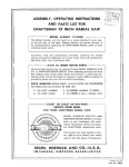
ASSEMBLY, OPERATING
AND
INSTRUCTIONS
PARTS LIST FOR
CRAFTSMAN
9 INCH
MODEL
NUMBER
RADIAL
SAW
113.29350
The Model Number will be found on a plate
at the left side of the base. Always mention
all correspondence regarding the CRAFTSMAN
ordering repair parts.
attached to your saw,
the Model Number in
RADIAL SAW or when
Carefully
read the instructions provided,
observe the simple
safety precautions and you will have many hours of satisfactory
use from your new Craftsman tool.
HOW
TO
ORDER
REPAIR
PARTS
All parts listed herein may be ordered through SEARS, ROEBUCK AND
CO. or SIMPSONS-SEARS LIMITED. When ordering parts by mail from
the catalog order house which serves the territory in which you live,
selling prices will be furnished on request or parts will be shipped at
prevailing prices and you will be billed accordingly.
WHEN ORDERING REPAIR PARTS, ALWAYS
INFORMATION
AS SHOWN IN THIS LIST:
GIVE THE FOLLOWING
1. The PART NUMBER
3. The MODEL NUMBER
2. The PART NAME
4. The NAME of item--RADIAL
COAST
FOR
113.29350
SAW
TO COAST NATION-WIDE
SERVICE FROM SEARS
YOUR
CRAFTSMAN
RADIAL
5AW
SEARS, ROEBUCK AND CO. and
SIMPSONS-SEARS LIMITED in Canada
back up your investment with quick,
expert mechanical service and genuine CRAFTSMAN replacement
parts.
If and when you need repairs or service, call on us to protect your investment in this fine piece of equipment.
SEARS,
IN
CANADA,
ROEBUCK
AND
SIMPSONS-SEARS
CO.-U.S.A.
LIMITED
Printed
Part
No.
in
U S. A.
63152
CRRFT. MR
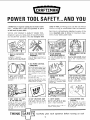
POWER TOOLSAFETY...AND YOU
safety in mind, permitting you to use the tool without
concern so long as certain basic rules are observed.
3 MINUTES
of required reading for the home Craftsman..,
whether this is your first purchase or you're
an old hand at power tools.
YOU'VE
JUST
BOUGHT
A QUALITY
designed
to give you many
and trouble-free
operation.
SEARS
We'd
more
ment
TOOL.
years of top performance
It's also designed with
like to call particular
attention
to some
important
rules to follow for maximum
of your Sears power tools.
of the
enjoy-
4. DRESS PROPERLYFOR THE
WORKSHOP
1. READ THE INSTRUCTION
MANUAL...
2. INSPECTTHE POWERTOOL
THOROUGHLY
3. FOLLOW
OPERATING
INSTRUCTIONS
CAREFULLY
completely,
accurately.
Pay special attention to safety precautions and use of safety features.
Set up the machine according
strucbons.
Make certain all
are included.
They have been developed to insure correct
procedure
and prevent accidents.
Get rid of loose clothing,
roll up
sleeves (or fasten securely), remove
your tie, wear a snug-fitting
shol:
apron.
7. DOUBLE-CHECKHOLDING
FIXTURES
8. KEEP CUTTING TOOLS SHARP
Make certain blades, drills, cutters,
etc., are in top shape. Dull tools
can cause rough cuts, excessive
chipping.., and accidents.
to ioparts
6. USE PROPERELECTRICAL
CONNECTIONS
Make certain proper voltage (I10 of'
220) is used. USE A GROUND WIRE;
AND A SUITABLE PLUG, IF REQUIRED.
Check fusing
requirements
of the
tool as outlined in the instruction
manual.
5. WEAR SAFETY GLASSES
Safety glasses or
recommended
for
operations.
eye shields
all power
are
tool
Get in the habit of turning
tool when not in use.
off
the
Disconnect
input cable from power
supply when adjusting toot from one
working position to another.
Lock all clamps tightly.
Spin parts by hand to check
misalignment
or looseness
turning on tool.
_il'_., _
against
before
_k,_,_" _,_=
I- I
9. DON'T EXCEEDTHE LIMITS
OF THE POWERTOOL
Abusing the power tool by doing
work beyond its capacity
reduces
its life and irrcreases the chance of
injury to the operator. Watch especially
the s_zes of the work and
feed rate.
THINK
10. KEEP SPECTATORSAWAY
11. SAFETY GUARDS
Curiosity
and interest
on the part
of the family is fine, but avoid inspections
when the power tool is
running
Accessory safety guards are available for most tools. Use of these
guards is highly recommended.
Keep protective
caps on
exposed, rotating shafts.
Carefully
plan
2
each
operation
ends
of
12. AVOID AWKWARDHAND
POSITIONS
Do not place hands in a position
where a sudden slip could cause
them to move into a cutting
tool
Do not force work abnormally
into
any cutting tool.
before
turning
on
tool
ASSEMBLING
2
3
AND
ADJUSTING
SAW
MOTOR
TO POWER
4
CONNECTING
6
15
YOUR
16
The a-c
7
motor
the capacitor
specifications:
used
start,
in this
Craftsman
non-reversible
Radial
type
with
Voltage
..........................
Amperes
.........................
Cycle ............................
Phase .........................
RPM ............................
17
SUPPLY
Saw
is of
the following
120
9.5
60
Single
3450
Rotation (viewing saw blade end) Clockwise
CAUTION:
This motor is wired for 120 volt
operation.
Connect
to 15
circuit and use a 15 ampere
MOTOR
13
1.
2.
3.
4.
5.
6.
7.
8.
9.
10.
11.
12.
12
11
10
9
20
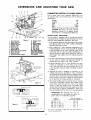
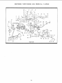
Figure
Yoke clamp arm
Swivel index knob
Safety lock key
Carriage lock knob
Elevation crank
Radial arm cap
Arm lock handle
Column tube key
Bevel index scale and indicator
Swivel index knob
Bevel Lock knob
Anti-kickbackpawl assembly
1
19
ampere
branch
time-delay
fuse.
SAFETY PROTECTION
The saw motor is equipped with a manual-reset thermal
overload protector, designed to open the power line circuit
when the motor temperature exceeds a safe value.
18
13. Discharge elbow
14. Handle
15. Guard assembly
16. "ON-OFF" switch
17. Table clainp
18. Allen wrench
19. Shaft wrench
20. Arbor wrench
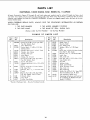
NOTE:WHENORDERING
REPAIRPARTSREFERTO
PARTSLIST FORCORRECTPARTNUMBER.
1. If the protector opens the line and stops the saw motor,
press the saw switch to the "OFF" position immediately
and _llow the motor to cool.
2.
After cooling to a safe operating
temperature,
the
overload
protector
can be closed manually
by pushing
in the red button on the motor capacitor cover. If the
red button
will not snap into place immediately,
the
motor is still too hot and must be allowed
to cool for a
while longer.
is closed.)
I
(An
audible
click
will
indicate
protector
3. As soon as the red button will snap into running position,
the saw may be started
and operated
normally
by
pressing
the saw switch to the "'ON" position.
4.
HOLE
FOR TABLE
)WN
gCRE W
COLUMN
_UPPORT
TABLE
REAR
(SEVEN,
Frequent opening of fuses or circuit breakers
may result
if motor is overloaded,
or if the motor circuit is fused
with a fuse other than those recommended.
Do not use
a fuse of greater
TOTAL)
capacity
Without
consulting
the power
company.
CL&MP
5. Although
the motor is designed
for operation
on the
voltage
and frequency
specified
on motor nameplate,
normal loads will be handle d safely on voltages not more
TABL_
than 10% above or below the nameplate
voltage. Heavy
loads, however,
require that voltage at motor terminals
R.H.
RIP
FENCL
FRONT
LEVELING
HOtE
BOTTOM
SIDE
Figure
OF
suPPORT
be not less than the voltage
6. Most motor
TABLE
T-
TABLE
SCREW
CORRECTLY
TABLE
IMPORTANT:
The following
recommended
for connecting
power source for trouble-free
INSTALLED
LEVELING
specified
may be traced
SC RE_&
"_
TOP
OF
JLength
TABLE
of
50
100
100
150
200
3
_*,sr _x///H'_///
U
---y/////i,,._,-NUT
L_/_L_N,,
:£k_',',
IN
feet
feet
feet
feet
feet
or
or
to
to
to
wire
sizes are
the motor to
operation.
Wire
Conductor
Figure
on nameplate.
to loose or incorrect
connections,
overloading,
reduced input voltage
(which
results when small size wires are used in the supply
circuit)
or when the supply
circuit
is extremely
long.
Always check connections,
load and supply circuit when
the motor
fails to perform
satisfactorily.
Check wire
sizes and lengths with the table in the next paragraph.
2
NiJT
T-NUT
troubles
(American
less
less
150
200
400
.................
.................
feet .............
feet .............
feet .............
Size
Wire
No.
No.
No.
No.
No.
Required
Gauge
No.)
12
10
8
6
4
I_'IAtL[D
For circuits of greater
creased
proportionally.
I.FdUI
3
length
the
wire
size
must
be
in-
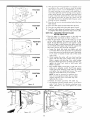
MOUNTING
THE SAW
ON A WORK
BENCH
The sow shoud be placed on a suitable sturdy work bench,
or Craftsman
Power Tool Bench. The base of the saw must
be mounted
*lush to a flat surface on the work bench to
prevent
distortion
of the saw base. The nuts, screws, and
washers which attach
the wooden
shipping skids to the
saw base may be used to secure the saw base to the work
bench, or tact bench.
ALIGNMENT
ALLEN
ARM LATCH
HANDLE
WRENCH
_3,/16
in.)
INSTRUCTIONS
NOTE: The seven basic "steps" that
essential in order to insure correct
COLUMN
ADJUSTING
SCREW
follow are
saw table
(TYPICAL)
KEYLOCKING
alignment.
WARNING:
Make
sure
the
power
not plugge d into an electrical
working
on the saw.
STEP
ONE--INSTALLATION
OF
cord
outlet
FRONT
is
when
TABLE
1. Place the large
table
board
upside-down
on floor.
Distinguish
between
the one through-bored
(leveling
screw) hole near the center of the board, and the seven
counterbore
holes. (See figure 2.) The counterbores
are
in the top surface of the board. Drive the T-nut into the
through-hole.
(See figure 3.)
2.
Place the 1/4-20 "'U" clip nut on the base cross members
to receive the center front tab!e attaching
screw.
3.
Place the
angles.
large,
front
table
board
on
table
Figure
4
support
4. Align the counterbore
holes with matching
holes in the
support
angles. Place a flat washer and a 1/4-20x
1"
pan-head
machine screw in each of the six counterbore
holes located above the angles. Use a 1/4-20 x 1-1/4 '_
pan-head
machine screw in the counterbore
hole at the
center of the table board.
5. Start
the leveling
the point
board.
6.
Install
screw into the T-nut
to protrude
Iockwashers
and
beyond
bottom
nuts on
the
but do
surface
not allow
of
six screws
front
in the
angles and tighten them finger tight. Start the 1/4-20 x
1-1/4"
pan-head
screw in the counterbored
hole near
the center of front board, leaving it about two turns loose.
STEP TWO--ELIMINATING
RADIAL
ARM
SIDE PLAY
1. Set the radial
arm at 0 J index position,
making
sure
the arm latch handle is in the detent notch, and tighten
the arm lock handle. (See figure 4.)
2. Apply side force with one hand on radial arm in both
directions. If side play exists, an adjustment is required.
3. Insert a 3/16-inch
Allen wrench into the socket-head
set-screw that adjusts the column tube wedge key, as
shown in figure 4. Rotate the set-screw slowly in (clockwise) until no side play can be felt in radial arm.
4. Check for binding by rotating
crank rotates with noticeable
the elevation
crank. If the
resistance, loosen the set
screw by rotating the Allen wrench counterclockwise
until
rotation
is normal. An effective method for finalizing
the
set-screw
adjustment
is to rotate the screw while
the
elevation
crank is being rotated,
checking for side play
in radial arm as the adjustment
progresses.
The adjustment is correct
when all side play of radial
arm is
eliminated
and only very slight additional
resistance
can be felt when rotating
the elevation
crank.
5. If some radial arm side play can still be detected
after
performing
the above adjustment,
it will be necessary
to adjust the forward
five screws through the right, and
left-hand
(olumn
supports as follows:
a
While
-otating
the elevation
crank, tighten
the five
column ,_djustlng screws slightly at the forward
edge
of column supports. Each screw should be tightened
only slightly, and each one the same amount,
until a
slight resistance con be felt when rotating
the elevation crank, then each screw backed off just enough
to restore a normal feel to the elevation
crank.
b.
Recheck the adjustment
of the column
key set-screw
as outlined
in preceding
6. After
the above
recheck the radial
7. When
adjustments
have
been completed,
arm for absence of side play.
all side play
has been eliminated,
tube key in place by tightening
bottom
of key. (See figure 4.)
STEP
tube wedge
instructions.
THREE--SQUARING
THE
lock the column
screws
CROSS
at
CUT
top
and
TRAVEL
1. Set the radial arm at 0 :' index position
arm lock handle.
(See figure 4.)
and tighten
2. Place
in figure
a square
on the
table
as shown
the
5 and
position the saw and square until the leg of the square
just contacts a tooth of the saw blade.
(Position
"A-,
figure 5.) Mark this tooth with crayon or chalk.
3. When
the blade
is moved
back
and
forth
on the
radial
arm, the saw tooth "A" should just touch the square at
all positions. If saw tooth "A" does not touch the square
at all points, make the following
adjustments.
the front arm latch
repeat if necessary.
screw.
Check
blade
travel
and
f.
When
the adjustment
is correct,
both arm
latch
screws should be snug against the arm latch handle
but not tight enough to bind the handle.
g.
Tighten
the Allen
set-screws
to secure
the
arm
latch
screws.
TABLE
SUPPORT
IABLE
SCREWS
Figure
_ELEVATION
ARM
5. After the cross-cut travel has been accurately
squared,
check the 0 ° position on the indicator
scale of the radial
SUPPOR_
(ANGLE)
arm cap to determine
if the 0 ° position
on the scale is
aligned with the index mark on radial arm. (See figure
8.) If not aligned,
proceed as follows:
6
CRAtdKRADIAL
ARM
a.
CAP
LO____
Rotate
locate
the
the
elevation
crank to a position
two access holes over screw
that will
heads
of
radial arm cap attaching
screws. (See figure 8.)
b. Loosen the two screws with a screwdriver
inserted
HANDLE
'c
___
ALLEN
WRENCH
through
the access
holes
in lift
crank.
c. Reposition
the radial
arm cap by hand until the
0: mark is aligned with the index mark and tighten
the two attaching
screws.
_
ELEVATION
-
INDEX
CRANK
Figure
o f!:
ACCESS
HOLES
CAP
FOR
AT]ACHING
Figure
a_
l,_
SCREWS
RADIAL
the saw guard.
2.
Raise the arm latch handle
out of the detent,
loosen
the arm lock handle (figure 4) and loosen the carriage
lock knob (4, figure 1). This will permit easy positioning
of saw blade during
leveling
operations.
3.
Lower the saw blade by rotating
elevation
crank until a
tooth just touches the table at the highest spot when saw
is moved to points 1,2, 3, and 4 (POSITION
1, figure 9).
This will locate the table high point. Spin the saw Blade
by hand and listen for "pinging'"
sound to pick up this
high paint.
4.
Loosen the table support screws at each side just enough
to allow the table support angles to slip when tapped
with a mallet.
(See figure
6.) If too loose, leveling
operations
will be difficult.
NOTE: Do not change elevation
of saw blade
5.
Move the saw blade to the low position
opposite
the
high point (located in step 3, above) at the same end
of table.
Assuming
the high area
to be at point
1
(POSITION
1, figure 9) the Blade would next be moved
to point 3 (POSITION
2, figure 9).
6.
Using a mallet, tap the table support angle under
3 until the table top just touches the saw blade.
7.
Tighten the two table support screws securely at the left
side of frame (figure
6), and recheck by moving saw
blade back and forth between
points 1 and 3 (POSITION 2, figure 9). If this end of table surface is level,
the saw will just touch the table at points from 1 to 3.
If not level, readjust point 3.
8.
Move the saw blade to point 2 (POSITION
3, figure 9).
Tap forward
end of right table support angle upward
with a mallet until the blade
just touches the table
surface.
9.
Move the saw blade to point 4 (POSITION
4, figure 9)
and tap rear end of table support angle upward
until
the blade just touches the table surface.
10.
Tighten the two table support
screws securely at the
right side of frame (reference
figure 6), and move saw
blade back and forth between
points 2 and 4 (POS!TION 4, figure 9) to make sure it touches at all positions from points 2 and 4.
11.
Recheck the adjustment
by moving
1, 3, 2 and 4 and make corrections
If saw tooth ("A",
figure 5) moves away
from the
square when moving the blade from the rear toward
the front of the table, loosen the table screws at the
b.
Recheck blade squareness
six ta!_le screws.
c.
Reverse this procedure
if tooth
square when moving
the saw
toward
the front of the table.
and,
if correct,
"A"
table
tighten
during
the
moves into the
from the rear
In extreme
cases, due to rough handling
during
shipment, performing
the above adjustment
procedure
may
not be sufficient.
Make the fallowing
adjustment
only
after tightening
the table screws and the cross-cut travel
cannot be squared
ment routine:
by performing
radial
down
arm
firmly
the preceding
a.
Position
the
la_ch handle
figure 7.)
b.
Using a 1!8-inch
Allen wrench,
loosen
screws that lock the arm latch screws.
c.
DO
ARM,
left side and tap the rear edge of front board forward
until the table
is square
with the saw blade.
(See
figure 6.)
4.
NOTE:
8
in 0
position,
into the detent
adjust-
press arm
notch. (See
the
two
Move saw blade forward
along steel square to determine in which direction
the arm must be adjusted.
arid
repeat
of the
CARPENTER'S
leveling
LEVEL.
operation.
point
set
d. If the saw blade moves away from the square as it
cemes forward,
loosen the front arm latch screw and
tighten the rear arm latch screw. Check blade travel
e.
remainder
USE A
PARALLEL
Remove
RADIAL
NOT
THE TABLE
RADIAL
ARM
1.
MARK
1
ARM
STEP FOUR--LEVELING
TO THE
7
if necessary.
If the saw blade moves toward the square as it comes
forward,
loosen the rear arm latch screw and tighten
5
saw blade to points
if necessary.
12. After preceding
leveling operations
are complete,
move
saw blade to the center of table to check for proper
table height at points 5 and 6 (POSITION
5, figure 9).
The table attaching
screw at point 5 pulls table downward when tightened and the leveling screw at point 6
pushes table upward
when tightened
(provided
screw
at point 5 has been loosened).
Thus, these two screws
work against
each other to adjust the center area of
saw table. Both screws should be tight, however,
when
leveling
has been completed.
POSITION
I
.os,.,o.
13.
Place the rip fence
table board.
in vertical
spacer
position
14.
Place the table
Place the rear table
16.
Install the table clamps at locations shown in figure 2
and tighten them firmly against the edge of rear table.
behind
behind
the front
15.
STEP FIVE--SQUARING
TO THE
board
behind
the rip fence.
the table
THE SAW
TABLE TOP
spacer
board.
BLADE
1. Place the edge of a framing
square
and against the saw blade as shown
on the table
in figure
10.
top
2. When the saw blade is square to the table top, no light
will be visible
between
the square
and face of saw
blade. Do not allow the square to rest against a tooth
of the saw. If light is visible between the square and face
of saw blade
(with square
leg held firm against
the
table top), perform
the following
adjustments.
POSITION
3
a.
Loosen the
a 5/16-inch
bevel lock knob just slightly
and with
Allen wrench loosen the two socket-head
screws that secure the handle to the yake. (See figure
11.) A screw is located
at each side of the swivel
index knob.
/
b.
POSITION
I
/
4
I
While
holding
the motor
with
square with the other hand, tilt
blade is square with table top.
one hand and the
the motor until saw
Then, while holding
the square firmly against the saw blade and table top,
tighten
the bevel
lock
knob to hold
motor
and
blade in position.
-oo
c. Move handle slightly
toward left or right until swivel
index
pin is properly
seated.
Push firmly
against
swivel index knob (keeping
swivel index pin seated)
and tighten
the two socket-head
screws. The swivel
index
pin should
slide freely
in the
handle.
NOTE:
It may be necessary
to perform
more
than one trial operation
before the saw blade
remains perfectly
square with table
top after
tightening
the screws.
d.
Recheck
e.
The indicators
(pointers) should read 0 ° on the bevel
scale. If not, loosen the indicator
attaching
screw,
adjust
indicators
to zero and tighten
the screws
securely.
for
blade
squareness
with
table
top.
HANDLE
SWIVEL
J
iNDEX
KNOB
BE'v EL LOCK
KNOB
lONE
POIbd_ER
Figure
10
ON
Figure
6
EACH
SOCKETSCREWHEAD
SIDE
OF
HANDLe',
_
j_
.-
11
b.
Remove the right-hand
carriage
cover
by first remov-
ing the carriage
lock knob (4, figure 1), by screwing
it all the way out. Then remove the two attaching
screws to free the cover.
c. Loosen slightly the carriage
bearing
retainer
nut just
abave the left rear carriage
bearing.
Then loosen
slightly
the corresponding
nut over right rear carriage bearing.
NOTE:
These nuts shauld
enough to permit the carriage
slip in their holes.
d.
be loosened
just
bearing
screws to
If the heel is in the direction
shown in "View A" (figure 13), insert a 1/8-inch
Allen wrench and loosen
the set-screw at left rear position,
then tighten
setscrew at right rear the same amount.
(See figure 14.)
NOTE: As one set screw is loosened,
the opposite one should be tightened
the same amount
BLADE
TRAVEL
gLADE
in order to retain the carriage
bearing
ment as accurately
as possible.
TRAVEL
e. If the heel is in the direction
shown in "View
13), loosen the right rear set screw
left rear set-screw the same amount.
T©
i,
v_EwB t[
L£FT
BLADE
TO
Figure
_CARRIAGE
HEELING
RETAINER
the
14.)
After the heel has been corrected,
tighten
the rear
carriage
retainer nuts and check for proper tension of
carriage
bearings
on the tracks.
g.
If front carriage
bearings
need adjusting
for proper
tension on the tracks, the adjustment
is made on the
right front
carriage
bearing.
Loosen
(slightly)
the
carriage
bearing retainer nut and rotate the set screw
until tension is correct.
After the tension has been
13
N U T/_//k"--'_
B" (figure
and tighten
(See figure
f.
RIGHT
BeArING_
CA _ [AGE
adjust-
izizi/
corrected,
tighten the carriage
bearing
retainer
nut.
(The adjustment
is correct
when there
is no side
play between
the arm and carriage,
and the carriage moves forward
and rearward
with very slight
resistance.)
h. Install
_L
v
/
X
L[FT/_. SIDE
,
__
I_ Ql(.
f.T
OF
CARRIAGE
FRONT]
_
,u.t
CARR,AGE_
BEA_Ir'4G
RETAINER
STEP
FRONT)
17
2.
NU]S
_
2.
Pull
HEEL (LEFT
AND
SAW
BLADE
FOR
If a
one
are
for
a.
lock
knob.
OF
SAW
by perform-
proceed
listed in
PRELIMINARY
CROSS-CUT
AT THE 0 ° POSITION
forward
of
fence
so that
until
saw
and tighten the
(See figure 15.)
saw
blade
is free
gap exists between
the saw blade and the square,
of two types of "heel" exists. The two types of "heel"
illustrated in views "A" and "B", figure 13. To correct
either type of "heel"
condition,
proceed
as follows:
R,-move the left-hand
carriage
two attaching
screws.
cover
by removing
the
radial
carriage
arm
lock
knob
blade
(4, figure
just
clears
the
1).
CAUTION:
Before cutting always
be sure that
the arm latch handle is fully engaged
in detent
notch.
RIGHT)
1. Place a square against the rip fence and the saw blade
as shown in figure 12. The long leg of the square must
be held firmly against the rip fence and the short leg
must not touch any of the teeth on the saw blade.
2.
SQUARING
saw guard assembly to the motor
clamp screw ta secure the guard.
motor
4. Tighten
THE
CHECK
carriage
If the cross-cut travel is not perfectly
squared,
with "STEP THREE" and make all adjustments
the "STEP THREE" procedure.
3. Lower the
table top.
14
I
STEP SIX--CHECKING
and
to rotate.
\
Figure
covers
SEVEN--DOUBLE
MAKING
_/
carriage
1. Recheck for correct adjustment
of the saw
ing "STEPS ONE through
SIX".
II
1. Attach
guard
,,,, k_'4
both
5.
Plug the power
6.
Insert safety lock key, turn the key and
to "'ON"
position.
(See figure
19.)
7.
Lower
top
8.
the
1!32-inch
To complete
fence hold
cord
radial
into
arm
deep.
receptacle.
until
THIS
saw
blade
IS ALL THAT
press the switch
cuts
into
table
IS NECESSARY.
a blade clearance
groove
in the table and
the handle
with the left hand and loosen
the carriage
lock knob
the motor with the left
with the right hand. Slowly pull
hand out to the extreme
end of
travelandthenpushthemotorbackthrough
thefence
to theextreme
rearposition.
Pushtheswitchto "'OFF"
position.
ATTACHING
AND DETACHING
THE SAW BLADE
I.
Remove
the shaft
nut and one loose
2
3
4
collar.
sT___
3.
Install
4.
Use the arbor
loose collar
on motor shaft making sure that
in the same direction
as shown in
and
wrench
shaft nut.
on motor
shaft
nut and
wrench on hex tight collar on motor
shaft nut. (See figure
17.)
OPERATING
1
2. Place the saw blade
saw blade teeth are
Figure 16.
CONTROLS
_6
(See figure
INSTRUCTIONS
FOR
the
18)
USE OF
1. Insert the key into the
(See figure 19.)
the shaft
shaft to tighten
KEY
slot and
AND
turn
SWITCH
counterclockwise.
2. Press the ON-OFF switch toggle on the right end to start
the saw motor. Press the left end of switch toggle to
stop the saw.
14---13--
NOTE: This saw can not be operated
without
the key, and likewise,
the key can not be removed from the lock while the saw motor is
running.
This locking
safety and protection
RAISING
AND
system was designed
of the operator.
LOWERING
THE
RADIAL
for
ARM
is accom-
plished by the elevation
crank (5, figure 18). One complete
turn of this handle will raise or Iowerthe radial arm 1/8-inch.
1.
2.
3.
4.
5.
6.
7.
8.
9.
10.
11.
12.
13.
14.
Yoke clamp arm
Swivel index knob
Safety lock key
Carriage lock knob
Elevation crank
Radial arm cap
Arm lock handle
Figure
Arm latch handle
Bevel index scale
Swivel index knob
Bevel lock knob
Anti-kickback pawl assy.
Handle
0N-0FF switch
LOCKING
THE CARRIAGE
complished
the knob
by the carriage
lock knob (4, figure 18). Turn
clockwise
to lock; counterclockwise
to unlock.
Avoid
excessive
ANGULAR
tightening
MOVEMENT
TO THE
RADIAL
ARM
is ac-
of the knob.
AND
LOCKING
THE
RADIAL
ARM are controlled
by the arm lock handle (7, figure 18)
and the arm latch handle (8). This handle is used to lock
the arm to the column for normal cutting. It should also be
used to eliminate
any play between the arm and the column
when levelling the table (Refer to STEP FOUR). This is done
18
by tightening the arm lock handle until the arm is snug on
the column, thus eliminating
looseness and allowing
the
arm to rotate smoothly.
The radial arm can be rotated
360
and locked ;n any desired
position.
The arm is unlocked by loosening
the arm lock handle
and raising the
arm latch handle out of the detent
notch. It is locked by
tightening
the arm lock handle. The radial arm has positive
stops at 0 ° and 45 ° , left and right, and is released
from
these index positions by raising the arm latch handle.
In order to provide the most positive
at the index positions, the fo!/owing
1. If the radial
handle,
8
turn
arm is already
the
arm
lock
and accurate
se_ings
is recommended.
indexed,
handle
raise the arm latch
(7, figure
18) ap-
proximately
1/4 turn counterclockwise
from the locked
position and move the radial arm off the index position.
2. Mo,,e
the
radial
arm
into
bump or jar) and depress
into the detent notch with
3. Lock the
fully
radial
hand
MOVEMENT
arm
the
index
position
(do
the arm latch handle
the palm of the hand.
by tightening
the arm
ROTATION
not
solidly
lock
AND
POSITION
OF
THE
MOTOR
cates the angular
position
of the motor
knob
index
handle
with
IN
THE
0 ' position. With the blade
index the radial arm to 45
(10, figure
scale indi-
respect
up and down. Pull the knob out to release the motor from
any of the index positions. At any other position, the swivel
index
knob is nat engaged.
The bevel lock knob
locks
to yoke when
the motor
is in any position.
ADJUSTMENTS
TO
COMPENSATE
Even though
the finest materials
and precision
workmanship have been used to minimize wear, after long use it is
reasonable
to expect some wear. Adjustments
have been
built into the Craftsman
saw to reduce or eliminate this wear.
REMOVING
RADIAL
ARM
3.
handle.
(See figure
2. Apply
side force with
directions.
If side play
SIDE PLAY
_TION
two
into
CRANK/ADIAL
arm in both
is required.
3/16-inch
Allen
that adjusts the
in figure 20. Rotate
until no side play
the elevation
crank. If the
resistance,
loosen the set-
Allen
wrench
counterclockwise
An effective
method for finaliz-
play in radial arm as the adjustment
progresses. The adjustment is correct when all side play of radial
arm is
eliminated
and only very slight additional
resistance can
be felt when rotating
the elevation
crank.
,
ADJUST
SCREW
insert a
set-screw
ing the set-screw adjustment
is to rotate the screw while
the elevation
crank is being rotated,
checking
for side
AR/v_
'.
WEAR
locking
screws,
the socket-head
screw by rotating
the
until rotation
is normal.
5.
AL
Loosen
wrench
FOR
4. Check for binding by rotating
crank rotates with noticeable
20.)
one hand on radial
exists, an adjustment
are controlled
in the normal cross-cut position
left and lock it. Then loosen the
column tube wedge key, as shown
the set-screw
slowly
in (clockwise)
can be felt in radial
arm.
1. Set the radial arm at 0 ° index position,
making sure the
arm latch handle is in the detent notch, and tighten the
arm lock
OF THE YOKE
yoke clamp
arm and position
the yoke 45 ° clockwise.
Secure the yoke clamp arm. The added
free table space
is now to the right of the blade
and ripping
should be
done from the right side of the table. The reverse is also
true for "'Out-Ripping"
by indexing
the radial
arm 45 °
right and positioning
the yoke 45 ° counterclockwise.
The
added table space is now to the left of the blade and ripping
should be done from the left side of the table:
to the
horizontal
from 0 ° to 90 °, in either vertical
position.
The
swivel index knob indexes the motor at 0 °, 45 °, and 90 °,
the motor
POSITION
knob to release it. The yoke clamp arm locks the yoke to
the carriage
in any position.
Push the arm to the right to
release it; push to the left to tighten. When "In-Ripping"
it
may be desirable
to have more free table in front of the
saw blade than is obtainable
when the radial arm is at the
tight.
YOKE are controlled
by the swivel index
18) and bevel lock knob (11). The bevel
AND
by the swivel index knob (2, figure 18) and the yoke clamp
arm (1). The swivel index knob automatically
indexes the
yoke at each 90
position and both 0"" positions.
Lift the
If some radial arm side play can still be detected after
performing
the above adjustment,
it will be necessary to
adjust the forward
five screws through
the right, and
left-hand
column supports as follows:
a. While
rotating
the elevation
crank,
lighten
(TYPICAL)
t
KEYLOCKJNG
SCREWS
b. Recheck the adjustment
of the column
key set-screw as outlined
in preceding
6.
Figure
the five
column adjusting
screws slightly at the forward
edge
of column supports.
Each screw should be tightened
only slightly,
and each one the same amount,
until a
slight resistance can be felt when rotating
the elevation crank, then each screw backed off just enough
to restore a normal
feel to the elevation
crank.
ING
After all adjustments
have been completed
radial arm for absence
of side play.
7. When side play
locking screws.
20
YOKE
is eliminated,
CLAMP
ARM
tighten
the
tube wedge
instructions.
recheck
the
column
key
ADJUSTMENT
The normal locking position of the yoke clamp arm (1, figure
18) is parallel with the radial arm. An adjustment
will seldom
be necessary,
however, it may be accomplished
as follows:
1. Loosen the carriage
lock knob (4, figure 18), mave the
carriage
out to the forward
end of radial arm and tighten
carriage
lock knob.
2.
Figure
21
Locate the index plate locking screw
yoke assembly. (See figure 21.)
at the rear
of the
3. Turn the locking
screw outward
at least 1/4-inch
from
tight position. This frees the index plate (figure 21) which
9
is keyed to the yoke clamp stud, thus permitting
the stud
to be rotated
when the yoke clamp arm is loosened.
4.
rocking
follows:
1. Remove
Loosen the yoke clamp arm, and with screwdriver
or
arbor wrench, rotate the yoke clamp stud a small fraction of a turn (clockwise when viewed from bottom), then
tighten the yoke clamp arm.
2. Place
Rotate
the locking
adjustment
screw back
by preventing
into position
movement
to secure
of index
5.
the
plate.
control
6.
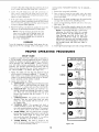
OPERATING
b.
"'ANGLE
OF CUT".
c.
each
Two
levers
are
e.
f.
Install
right-hand
involved
marked
purple
circle.
"CARRIAGE
PIVOT".
with
the
numeral
Two controls
carriage
"'POWER
SWITCH".
SET-UP
GUIDE
BLUE
PURPLE
ANGLE
OF
CUT
ORANGE
GREEN
in a
CARRIAGE
PIVOT
CARRIAGE
LOCK
O
in this
knob and yoke
numeral
"3"
in
YELLOW
BLADE
controls used in angular
the motor to provide the
are: bevel
lock
knob
numeral "'5" in a ye!!ow
of these controls.
This switch
is located
turns.
is removed and
very slight
re-
cover and carriage
"CARRIAGE
LOCK".
The carriage
lock knob
is
rotated
clockwise
to secure the carriage
on radial
arm, and counterclockwise
to release it. The numeral
"4" in a green circle is at the center of the knob.
"'BLADE ANGLE".
The two
positioning
and indexing
of
desired
saw blade
angle
and swivel index knob. The
circle is attached
to each
the
wrench,
rotate the two socket(clockwise)
a fraction
of a turn.
in re-
"2"
are used
motor
of motor
or two
PROCEDURES
and indexing
the angle of radial
arm lock handle
and arm latch
operation.
They are: swivel index
clamp arm, each marked
with the
an orange
circle.
d.
nuts one
as _.qlows:
"'DEPTH OF CUT". Diagram shows the elevation crank
which is used to raise and lower the blade.
The
numeral
"1" in a blue circle is on the crank handle.
handle,
retainer
the
by removing
screws.
GUIDE
a.
leasing,
securing
arm. These are:
under
just the weight
retainer nuts, until all side play
the carriage
moves with only
sistance.
1. Notice
the radial
arm trim strip, the forward
end of
which contains six diagrams numbered
"'1 "° through "6".
Each number is in a colored circle, and a corresponding
number in an identical colored circle will be on the particular operating
control
member
involved.
each
saw table
until
the right hand carriage
cover
lock knob and two attaching
Using a 1/8-inch
Allen
head set-screws inward
L..
blade.
on
crank
be adjusted
riage bearings
may bind
on the track.
This
adjustment
should
be made,
by alternately
adjusting
the set-screws and carriage
bearing
A combined
number and color code system, designated
as
a "SET-UP GUIDE", has been applied to the saw in order to
simplify
the location
of controls required
for a particular
set-up operation.
The "SET-UP GUIDE"
is both a convenience and safety measure,
particularly
for inexperienced
operators.
The operator
should become familiar
with this
feature
before operating
the saw. A brief explanation
of
the "SET-UP GUIDE"
is as follows:
(See figure 22.)
Locate
and
wood
may
NOTE: If all carriage
side play is removed
by
tightening
the set-screws,
when the carriage
bearing
retainer
nuts are tightened,
the car-
To test for looseness in the carriage,
firmly grasp the carriage across the two carriage
covers and apply
a firm
2.
of
looseness
4. Loosen carriage
bearing
(See figure 14.)
CARRIAGE
SET-UP
the saw guard
a block
3. Remove
carriage
NOTE: It may be necessary to loosen the yoke
clamp arm so that end of lacking
screw can
enter a notch of the index plate. This would alter
the arm adjustment
slightly but not enough to
be of any consequence.
PROPER
Noticeable
and turn elevation
rests on the block.
5. If the yoke clamp arm still does not line up parallel
ta
the radial arm, !oosen it and again move the yoke clamp
stud. Continue
this operation
until the yoke clamp arm
is properly
aligned when tightened.
6.
motion.
in
RED
the
upper left area of the carriage
and has the numeral
"6 '_ in a red circle directly
under it.
Figure
10
22
ANGLE
lock knob.
SAFETYINSTRUCTIONS
Safety is a combination
of common sense and
all times "when the saw is being used.
alertness
long sleeves down with cuffs
sleeves. NEVER STOP BEING
at
of
2.
WARNING:
Do not allow familiarity
that comes
from frequent
use of the saw to become commonplace.
Always
remember
that a careless
fractian
of a second
is sufficient
to inflict
sew_re
1.
3.
injury.
DRESS PROPERLY.
Operation
of the saw is simple,
inattention
AVOID
can produce
AWKWARD
fastened, or wear short
CAREFUL.
One moment
a painful
HAND
injury.
POSITIONS.
Do not allow
hands to assume a position in which a sudden
cause them to move into the saw blade.
slip can
NEVER TWIST
will bind
WORK.
Twisting
the work
piece
the blade and produce
a "kickback".
SAFETY PRECAUTIONThe motor
safe
shaft
has
a cap threaded onto the unused end of motor
shaft and should not be removed.
and easy--when
properly
accomplished.
Always
be
alert. Do not wear a tie or other loose articles.
Keep
LUBRICATION
This Craftsman
saw is a fine
machine
and
should
PERIODICALLY
be given
the best of care. If kept clean and properly
lubricated,
it
will give many years of trouble-free
service. Before describing the various points which may periodically
require
lubrication, IT IS MORE IMPORTANT
TO FIRST MENTION
THE
VARIOUS
SPOTS WHICH SHOULD
NOT BE LUBRICATED.
NO
LUBRICATION
AT
lubricate
REQUIRED
any
ball
races
or ball
3.
not
Do
not lubricate
ball bearings
the motor bearings.
These are sealed
and require
no added
lubrication_
Do
not
carriage
bearings
or
bearings.
is the sawing
of wood
across the grain.
engine
THESE POINTS
oil and
refer
to
Parts List
and the key and column support.
An oil hole is provided
in the top of elevation
crank to
facilitate
lubrication
of the elevation
shaft and radial
ing
SAW
the
elevation
crank
and
are lubricated
radial
arm
by remov-
cap.
OPERATIONS
NOTE:
lumber,
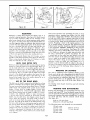
CROSS-CUTTING
Cross-cutting
auto
arm cap bearing
surface.
4. The threads on elevation
shaft
tracks.
STANDARD
LUBRICATE
10-30
1. Apply a few drops of oil along the swivel index pin only
if the pin has a tendency
to stick, Remove the left-hand
carriage
cover and use oil sparingly
to prevent
it from
getting on the ball bearings or races.
2. A light film of oil can be wiped on the face of the column
tube and keyway
to lubricate
the fit between
this part
THESE POINTS
Do
lubricate
Use SAE No.
for locations.
Boards
When
cross-cutting
normal
the long end of the board
pieces
should
placed
to the left of the saw blade,
board is normally
held by the left hand
the sawing operation.
are sawed with the grain running the length of the board. If
a straight cross-cut is desired,
the board is placed on the
saw table against the fence so that the grain is parallel
to the fence. (See figure 23.)
The radial
arm
must be positioned
of
be
as the
during
at 0 _ as indicated
by the radial arm position indicator.
The arm latch
must be indexed and arm lock handle tightened.
to paragraph
of the Radial
2.
"'Angular
The yoke must be indexed
the saw blade, perpendicular
yoke
3.
entitled
Arm".)
clamp
arm
placed
at
Movement
The motor must be positioned
the bevel scale, and locked.
4. Turn the elevation
crank
and
Locking
the 0 ° position,
to the rip fence,
in locked
at
to lower
handle
(Refer
making
and the
position.
0 _, as indicated
the saw until
by
the blade
teeth are approximately
1/32"
below the table surface
and ride in the saw slot made when performing
the
"PRELIMINARY
CROSS-CUT AT THE 0 ° POSITION".
D_RECTION_/
5. Push
the saw carriage
the blade
6. Adjust
table
clears
Figure
7.
23
11
is behind
to the rear
of the radial
the saw guard
so the bottom
is parallel
and set the anti-kickback
pawl
assembly
the board to be cut.
Turn the switch
the saw motor.
arm
so
the rip fence.
key "'ON"
and
press the switch
to the
so it
to start
/
_L
i
4
I
i
I
/
/
Figure
8. Hold the board firmly
hand and grasp the
against
handle
24
Figure
the rip fence with the left
with the right hand.
of the board
securely.
tighten
the guard
clamp
screw
CAUTION:
The nose of the guard refers to that
end of the guard which is opposite
to the end
9. The cut is then made by pulling
the carriage
forward
until saw blade cuts through
the work. When
the cut
is complete,
the saw should be returned
to the back of
the radial
arm and the switch turned
"OFF".
When
which mounts the anti-kickback
Always
rip from the nose of
Warning
Label on guard.
more experience
is gained
by using the saw, it will
be noticed
that when
pulling the saw forward
during cross-cutting,
the saw blade
tends to feed itself
through
the work due to the rotation
of the blade
and the direction
of feed. Therefore,
the operator
should
develop
the habit
of holding
his right arm
straight
from
the shoulder
to the wrist.
After using
this method a few times, the operator
will find that it is
necessary to rol! or rotate the body from the waist up.
h wil! soon become apparent
that very little effort
is
required
to move the saw blade through
the work, and
in most cases, the right arm is used merely to control
the rate of feed. It will also be discovered
that when
pawl assembly.
the guard.
See
At the opposite
end of the guard,
loosen the wing screw
holding
the anti-kickback
pawl
assembly
and lower the
assembly until the tips of the pawls are 1/8-inch
below the
top surface of the
screw securely.
board
to
be cut and
tighten
the
wing
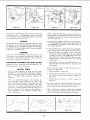
IN-RIPPING.
"In-rip"
refers to a position
when the saw
blade is between the motor and fence, parallel
to the fence.
(See figure 25.) To place the saw in this position, unlock the
yoke, disengage
the swivel index knob and rotate the yoke
90" clockwise
(viewing it from the carriage)
until the swivel
latch pin automatically
indexes the yoke at 90 ° . Lock the
yoke securely. Position the carriage
on radial arm to provide
proper width of cut by measuring
from edge of saw blade
to rip fence with a scale. Position the discharge
elbow on
the guard so that sawdust will be blown
toward the rear.
Turn the saw_"ON"
and lower the radial
arm until saw
cross-cutting
a thick
board,
movement
of the saw
through the work must be retarded.
By holding the right
arm (right hand normally
grips the saw handle) straight,
the operator
can easily control
the rate of feed, thus
preventing
the saw blade from overfeeding
and stalling
blade cuts into the table top approximately
1/32-inch
and
turn the saw "OFF". Adjust the saw guard and anti-kickback
pawl assembly as described
previously.
the saw motor, which must be avoided
whenever
possible. In some cases it may become necessary to cross-cut
boards that extend over the saw table on one, or both
sides. This can buckle the board and bind the saw during
the cut. To eliminate
this condition
the ends of the board
The board
must be fed
into the
saw blade
from
the right
side of the table.
Therefore,
the normal
position
for the
operafor
is at the right side of table. With the left hand,
safely clear of the blade
and holding
the board
dawn
against the table and rearward
against the fence, use the
right hand to feed the board
into the saw. The left hand
should remain
stationary,
serving as a guide only. As the
should be supported.
Figure 24 shows a typical
support
that can be easily constructed
to facilitate
cross-cutting
of long boards.
RIPPING
right hand approaches
the left hand, use a push
the right hand to complete
the cut. Do not leave
board unsupported
so that the spring of the board
it to shift on the table. (See figure 24.)
Ripping is sawing wood with the grain. It is always
done
with the help of the fence as a guide to position the board
and produce
the desired width of cut. Since the work is
pushed along
edge in order
to be cut, and
25
the fence, it must have a reasanably
straight
to make sliding contact with the fence. Also,
stick in
a long
causes
OUT-RIPPING.
"Out-rip"
refers to a position
when the
motor is between
the blade and the fence. Normally,
this
position is used only when the width of the required
ripped
board cannot be cut from the in-rip position. To place the
saw in the "out-rip"
position, the yoke must be rotated and
indexed
90 _ counterclockwise
from the cross-cut position
and lacked.
The same procedure
for pre-setting
the table
top (see "'In-Ripping")
and adjusting
the saw guard
and
anti-kickback
pawl
assembly
(see "Ripping")
should
be
the work must make solid contact with the table to prevent
"wobble"
or "rock".
A straight
edge should be provided,
even if it means temporary
nailing of an auxiliary
straightedge board to the work. If the work piece is warped,
turn
the hollow side downward
on the saw table.
The saw guard
and anti-kickback
pawl assembly
should
always be Jsed in ripping
operations.
Before ripping,
and
after the sow has been positioned
prior to sawing, the saw
guard and anti-kickback
pawl assembly
must be properly
adjusted.
Loosen the guard
clamp
screw and lower the
nose of the guard to within 1/8-inch
above the top surface
followed.
The same procedure
for sawing
is used except
that now the operator
stands at the left side of the table
and a push stick is normally
not required.
12
Figure
26
Figure
RESAWING
Resawing
is cutting
thick
boards
into
thinner
ones.
It
Dado head operations
are essentially
the same as those
operations
using a standard
saw blade--but
the dado
is
head takes a bigger
bite, therefore,
the work-piece
should
be held more firmly. When a groove
wider than the dado
head is needed, make two or more passes, with cuts spaced
to overlap
a trifle. Dado work is performed
in the cross-cut
position.
Ploughing
is done in the ripping
position.
If the
rip or plough
position
is used, the saw guard
and antikickback
pawl assembly
should be adjusted
as described
in the paragraph
"RIPPING".
Rabbeting
is done with the
motor shaft in a vertical
position.
(See figure
28.) When
rabbeting,
the motor is indexed 90 ° to the vertical
position
so the blades are between
the table top and motor, and
the yoke is indexed
90 ° clockwise
and locked.
The saw
is moved back on the radial
arm and locked to the arm
actually
a ripping
operation.
(See figure 26.) Small boards
up to 2-inches
maximum
width
can be resawed
in one
pass. Larger boards up to 4-inches maximum
width require
two passes, one along each edge of the board, When two
cuts from opposite
edges are required,
they should overlap
1/2-inch
from the approximate
center of the board.
If the
first cut is too deep, the kerf will close and bind the saw
on the second cut, with some danger of "'kickback". Also,
when the kerf closes, the two sides of the cut are no longer
parallel
to the saw blade,
and the saw will cut into them
and spoi! accuracy
and" appearance.
Keep the same face
of the board against the fence when making both cuts.
When
cutting
boards
thicker
than
3-1/2
inches,
a
fence
when
fence
should be used which extends 3-inches above the table top.
When
cutting
boards
thicker than 4-1/2-inches,
cut both
sides and finish the cut with a hand saw.
BEVEL AND
MITER
set at the
desired
miter
angle
to the fence,
or ripping
Miter cuts
then
USE OF THE
DADO
of the
If the
MOLDING
OR
SHAPING
This work
is performed
with
Craftsman
Molding
Cutter
Heads, and a set of cutters depending
on the type of molding cut desired. The saw is positioned
in the same manner
as that described
for rabbeting.
(See figure 29.) Since the
position
of the cutters can be adjusted
with respect to the
fence and table top, any or all of the cutter shapes may
be used.
the
blade (only)° is tilted, with respect to the table top, to the
desired
bevel angle. This cut is usually referred
to as a
compound
miter. (See figure 27.)
The dadc_ saw (or head) is a special
grooves c_nd dados. The Craftsman
forward
desired.
position
to cut the desired width of rabbet
in the edge of
the board. The bottom of the saw guard should be parallel
to the fence and the discharge
elbow
directed
to the
rear of the saw.
can be made only from a cross-cutting
position
when the
blade and radial
arm are at some angle other than 90 _
to the fence. A bevel miter cut is a cut which is both beveled
and mitered.
This cut is made with the blade and radial
arm
the amount
of the blade
extending
is equal to the depth of the rabbet
depth of the rabbet is large, do not attempt
to cut it in one
operation.
Lower the radial
arm until blades
are in a
CUTS
Bevel cuts can be made from either a cross-cutting
position by tilting the blade to the desired angle.
28
HEAD
set of blades for cutting
8-inch Kromedge
Dado
The Molding
Cutter Head.
Set may be purchased at any Sears Retail Store or Catalog
Order
House. The complete
head consists of two outside
blades
1/8-inch
thick,
six chipper
blades
1/8-inch
thick
and paper washers for 1/16-inch
width adjustments.
With
these blades, grooves may be made in widths of 1/8-inch,
1/4-inch,
and additional
widths
in steps increased
by
1/16-inch
each, uplto a maximum
of 13/16-inch.
Outside
blades may be used alone,
but chippers
cannot
be used
alone.
When the maximum
13/16-inch
width
of dado is
I
used on the motor shaft, the outside loose collar must not
Cutter
Guard
ROUTING
should
AND
be
used with
Molding
DOVETAILING
Routing
and dovetailing
are accomplished
with the motor
indexed
and locked 90 ° from horizontal,
except that this
time the externally
threaded
stub end (opposite
the normal
blade end) is between the motor and table top. The following chucks will mate, with this external
1/2-20
thread.
(See figure
30.)
O-inch
be used. The width of the dado can be reduced while using
the loose collar and two or more passes may be made with
the work to obtain the desired width of cut. Whenever
two
to
5/64-inch
The following
or more chippers
are used, the cutting
ends should
be
staggered
as evenly as possible around the circumference.
Fractioncl
adjustments
in thickness of the head can be
made by using paper washers between
the outside blades
and chippers.
13
1/4-inch
Chuck
to 1/2-inch
routers
1/8-inch
1/4-inch
3/8-inch
t/2oinch
router
router
router
router
5/8-inch
router
and
Key Chuck
dovetails
are recommended:
3/8-inch
1/2-inch
dovetail
dovetail
Figure
Routing
may
29
Figure
be performed
by either
moving
30
the work
Figure
with
3.
a stationary
router, or by clamping
the work to the table
and moving
the router.
Always
approach
the router
bit
from the left-hand
side of the saw.
be converted
to a horizontal
drill
angle
31.)
while
the
work
is parallel
Stabilizing
washers
proved
appearance
THIN
should
be used with
of the finish cuts.
HELPFUL
blades
im-
a.
b.
33
Figure
14
the
position
(1, figure
35).
Position
used for
maximum
cross-cut
c. Position
used
figure 35).
34
in which
Normal
rial and for
figure 35).
There is a possibility
that during (or after) shipment,
the
wood front table;
spacer
board;
or rear table might
become slightly
warped.
Lay a straight-edge
across the
surface of the table and check for gaps or high spots
on the table. Any portions of the table that are not flat
should be planed and sanded until flat. Sanding can be
done by using one of the two key chucks referred
to
under "ROUTING"
and a Craftsman
moulded
rubber
6-inch sanding
disc.
Figure
from
posi-
Remove the fence and replace
it with a temporary
fence made from a straight
piece of scrap lumber.
Proceed to cut slots in the original
fence where the
gap between
the fence and front table was determined to be the greatest.
(See figure 34 for slotting
arrangement.)
6. There are three positions
located.
(See figure 35.)
HINTS
1. The life of the composition
saw table may be greatly
lengthened
if a 1/4-inch
piece of plywood
is tacked to
the table top after leveling.
Then all cutting
would
be
done in the added
piece of plywood
instead
of the
table top.
2.
the work
b. Replace
the fence (after
slotting)
behind
the front
table with the slots toward
the rear and tighten the
table clamps.
BLADES
for
with
In the event the fence is warped and cannot be straightened by tightening
the table clamps, proceed as follows:
a.
FOR
or routing
5.
Using the lO-_nch sanding disc, mounted
on the saw end
of the motor, the saw may be converted
into a sander that
will operate
in any position.
The loose collars
should be
used on both sides of the sanding disc.
WASHERS
top
A scale may be attached to the fence to aid the operator
when measuring lengths during cross-cut operations.
This
is accomplished
by tacking a yard stick to the fence as
shown. (See figure 33.)
for boring
SANDING
STABILIZING
the table
32
4.
by using one of the recommended
chucks and proper drill.
For drilling
holes on an angle, the radial
arm should be
positioned
to the desired
to the fence. (See figure
sanding
Figure
stationary,
the arm latch handle may be prevented
automatically
indexing
by raising it to the vertical
tion. (See figure 32.)
BORING
The saw may
When
31
greater
for
bevel
maximum
and
fence
on 1-inch
miter
"out-rip"
can
be
mate-
capacity
(2,
capacity
(3,
7.
Keep all cutting tools, such as saw blades, drills,
ing cutters, dados, etc., sharp, and do not "force
work enough to drastically
reduce motor speed.
8.
When using planer,
molding,
or dado blades, repeated
light cuts will produce best results. Deep cuts reduce the
quality
of the finish and often produce
"tear-outs".
Figure
35
moldfeed'"
9. An ,:uxiliary
table top for molding
or shaping may be
consnucted
similar to the one shown in figure 36. Notice
the i:ape of the back guide fence which has a cut-out
5-in_ hes wide at the center to provide
adequate
clearanc_ for the molding
head and cutters. Also, a wider
clea:ance
(marked "A")
should be cut out to allow for
the _,aw motor. Make sure the front edge of the auxiliary
tabh' is parallel
with the forward
surface of the guide
feno _ The auxiliary
table
top can be attached
to a
worl_ bench with "C" clamps.
NOT[
DIM[NSION
B[ LARG[
TO
CLEAR
"A" TO
_NOUGH
MOTOR
SUPPORTS
I'
FOR
TROUBLE
SHOOTING
SEE PAGES
FOR
16 AND
PARTS
SEE PAGES
17
LISTS
18 TO
15
CHARTS
23
_ 2"
--
32"
LONG
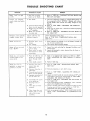
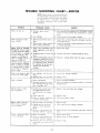
TROUBLE
TROUBLE
Blade "heels"
or left.
PROBABLE
to right
Cannot "rip"
wood smokes
properly,
and motor
SHOOTING
CAUSE
REMEDY
1. Heel has not been
taken out of blade.
1.
1.
1. Check for sharpness of blade or warped
board.
Refer to
the paragraph
entitled
"'RIPPING."
Ripping with hollowground
blades when boards
are badly
warped
is very
difficult.
2. Refer to "STEP THREE--SQUARING
THE CROSS-CUT
TRAVEL."
Dull
blade.
stops.
2.
Crosscut travel and rip
fence are not squared.
3. Radial arm not locked
in 0 ° position,
4. Blade not squared
the table top.
Elevation
roughly;
Motor
crank
chatter
will
not
operates
exists,
run.
Blade
does
not maintain
constant
depth
across table.
Blade
does
not
of
cut
cut
squarely,
or repeat
cannot
be secured.
Column
adjusted
tube key
properly.
1. Protector
broken.
Motor will not run and
fuses "BLOW."
cuts
CHART
open;
2.
Low
voltage.
I.
Short
circuit
to
not
Refer to "STEP
HEEL (Left and
SIXCHECKING
Right)."
3.
Make sure the radial arm is locked
in the 0 ° position.
4. Refer to "STEP FIVE--SQUARING
THE TABLE TOP."
circuit
in line
line cord
wires.
2.
all terminals
terminals.
Inspect
shorted
and
1. Plane of table top not
parallel
to horizontal
plane through
radial
arm.
2. Table badly
warped.
1. Table is not aligned
FOUR--ADJUSTING
ARM."
1. Excessive free play in
column tube key
adjustment.
2. Excessive free play in
radial arm.
1. Refer to "STEP
SIDE PLAY."
2.
Eliminate
Refer to "STEP
TRAVEL."
Crosscut travel and rip
fence are not squared.
3.
4.
Improper
movement
arm for miter cuts.
4.
S. Saw blade not square
to the table top.
6. Bearings loose on
track.
7. Yoke does not index
for
in motor
indexed
RADIAL
terminal
properly
BLADE
TO
ARM
button,
damaged
FOR
located
insulation
box for loose
on
and
or
with radial
arm. Refer to "STEP
THE TABLE PARALLEL TO RADIAL
top.
TWO--ELIMINATING
looseness
in arm
latch
THREE--SQUARING
RADIAL
ARM
screws.
THE CROSS-CUT
Adjust arm latch handle for correct indexing
at 90 ° which
will produce a correct 45 ° setting. Refer to "STEP THREE
SQUARING
THE CROSS-CUT
TRAVEL."
5. Refer to "STEP FIVE-SQUARING
THE SAW BLADE TO
THE TABLE TOP."
6.
Refer to paragraph
entitled
MENTS TO COMPENSATE
7.
Check to see that yoke indexes properly
and that carriage
bearings
are not loose on tracks. Refer to "STEP SIX CHECKING
THE SAW BLADE FOR HEEL."
8.
Refer to paragraph
entitled "YOKE CLAMP ARM ADJUSTMENT"
under "ADJUSTMENTS
TO COMPENSATE
FOR
WEAR."
properly.
Yoke clamp does not
tighten
yoke; or looseness is felt in yoke
assembly.
table
2.
3.
of
Replace
plug
BLADE
THE SAW
1. Reset protector
by pushing in on red
top of motor junction
box.
2. Check power line for proper voltage.
1. Inspect
shorted
SAW
and
Check adjustment
of key plug.
Refer to "STEP TWO--ELIMINATING
SIDE PLAY.'"
cord or plug.
2. Short circuit in motor
terminal
box or loose
connections.
8.
THE
16
"CARRIAGE,"
FOR WEAR."
under
"ADJUST-
TROUBLE
SHOOTING
NOTE:
Motors
CHART--MOTOR
used
on wood-working
tools
are particularly
susceptible
to the accumulation of sawdust and wood chips and should
be blown
out or "vacuumed"
frequently
to prevent
interference
with normal
motor
ventilation.
TROUBLE
PROBABLE
Motor will not run.
Motor will not
fuses "BLOW."
run and
1.
Protector
broken.
2.
Low voltage.
1. Power
2.
3.
Motor starts slowly or fails
to come up to full speed.
resulting
in
fuses or tripped
breakers).
overloading
Incorrect
Reduce
too
2.
Increase
wire
of power
3.
Request
a voltage
line.
4.
Install
trip
1. Correct
low
2.
relay.
of existing
distribution
fuses
Starting
plug
voltage.
for
terminals
in motor
terminals..
line
damaged
terminal
insulation
box for loose
load.
sizes, or reduce
length
of wiring.
check
from
the
power
company.
in power
relay
not
not
gen-
operating.
overloaded.
Replace
1. Correct
Improper cooling. (Air circulation restricted
through
motor
due to sawdust, etc.)
2.
1. Replace
2.
Open
2.
Replace
3.
Loose or broken
in motor terminal
3.
Check
relay
1. Starting
coil.
relay
connections
box.
not operating.
2.
Voltage
too low to permit
motor to reach operating
speed.
3.
Fuses or circuit
have
1. Motor
2.
3.
do
have
breakers
sufficient
do
fuses.
voltage
overload
relay
17
condition.
and
to provide
normal
check
voltage.
line
air
circulation
relay.
and
repair
wiring.
relay.
2. Correct
the
3.
Replace
units.
fuses or circuit
1.
Reduce
motor
load.
2.
Replace
fuses
or circuit
3.
Replace
relay.
low
capacity.
Starting
relay
not operating
(motor does not reach normal
sp_ed.)
condition.
1. Replace
capacity.
overloaded.
Fuses or circuit
not
breakers
sufficient
correct
Clean out sawdust
through
motor.
1. Burned relay contacts (due to
extended
hold-in periods
caused by low line voltage,
etc.)
not
Frequer t opening
of fuses
or circu,t breakers.
cord and
wires.
I.
with
for proper
other
or circuit
1. Low voltage--will
relay.
2.
stalls
General
1. Motor
Starting
relay in motor
will not operate.
1. Inspect llne
and shorted
Inspect all
or shorted
and
wires
line
2.
overloaded
the capacity
erating
and
systems.)
2.
overheats.
Undersize
power
company's
facilities.
(In many
sections of the country, demand
for electrical
power
_xceeds
4.
output.
line
Check
long.
in voltage causes a reduction of 36% in maximum
blown
circuit
1. Reset protector
by pushing in on red button, located
on top of motor junction
box (indicated
by audible
click).
2.
lights,
appliances
motors.
maximum
power output of
which the motor is capable,
while a reduction
of 20%
Motor
circuit
Short circuit in line cord or
plug.
2. Short circuit in motor terminal
box or loose connections:
of motor decreases rapidly
with
decrease
in voltage
at motor terminals.)
For
example:
a reduction
of
10% in voltage
causes a
reduction
of 19% in
Motor
open;
REMEDY
1.
Motor
fails
to develop
full power. (Power output
power
CAUSE
line
voltage
condition.
breakers
breakers.
with
proper
capacity
PARTS
CRAFTSMAN,
9-INCH
RADIAL
LIST
SAW,
MODEL
No.
113.29350
All parts illustrated in Figures 37 through 40 and listed under part numbers may be ordered through any Sears retail
mail order store. Order parts by mail from the catalog order store which serves the territory in which you live. In several
instances, part numbers are listed for COMPLETE ASSEMBLIES. All parts are shipped prepaid within the limits of the continental United States.
AS SHOWN
WHEN ORDERING REPAIR PARTS, ALWAYS GIVE THE FOLLOWING
INFORMATION
ON THIS LIST:
1. THE PART NUMBER
3. THE MODEL NUMBER 113.29350
2. THE PART NAME
Always
order
4. THE NAME
OF ITEM--RADIAL
by Part Number--not
by Key Number
FIGURE
Key
No.
Part
No.
2
3
63032
4
5
115109
63038
6
60059
7
8
63033
30613
9
448011
191230
60169
Blade,
Wrench,
Hd.
26
27
60030
63037
Steel
28
222405
Lock
29
2 Cord
3O
31
30505
63036
63070
32
33
118647
63002
35
453676
63053
Lock
Washer,
Arm
Clamp
Handle,
Arm
Arm, Radial
Screw,
116120
Washer,
Steel
Arm
37435
63034
Hd. Cap, Plain
*Wrench,
Hex. "L",
Track
5/16-18
x 1/2,
1/4
*Screw,
No. 6-32 x 5/8,
Fill. Hd. Slotted,
Cad.
16
17
3540
30495
Wrench,
Arbor
Nut, Shaft
18
63017
Collar,
Hardware
Saw
Item--May
S.A.E.
Type
23C1,
Latch
*Screw,
*Standard
1/4
Split Lock 5/16
60053
448907
Type 23C1,
x 1, Fill.
*Screw,
No. 8-32 x 3/8,
Pan Hd. Slotted,
Steel
63035
Description
63062
37861
Med.
No.
Part
No.
19
*Washer,
Clamp,
LIST
2O
21
Trim, Radial Arm
*Screw, Mach.,
1/4-28
Slotted, Steel
11
14
15
Key
No.
*Screw, No. 8-32 x 5/16,
Pan Hd. Slotted,
Steel
10
13
PARTS
Description
9404365
12
37
36
37
38
x . ! 25 x .078,
Hex. Socket
Across
Flats
Type 23C1,
PI. Steel
Blade
be
Purchased
Locally.
18
SAW
63052
63051
Saw,
9 tr
Shaft
Key, Safety Lock
Washer,
.505 x 1 x 1/32,-Steel
Plug
*Screw, Set, 1/2-20 x 3/8,
Hd., Flat Pt., BIk. Oxide
*Wrench,
Hex "L",
Latch, Arm
Hex. Socket
1/8
Across
Flats
Disk, Color (2)
*Nut, Hex. Jam, 1/2-13
x 3/4x
5/16
Cap, Radial
Pin, Roll
Arm
Washer,
Knob
Shaft, Crank Knob
Knob, Elevation
Crank
39
40
63069
63054
Disk,
Color
Ring,
Retaining
(1)
42
9404351
Screw, No. 6-32 x 5/16,
Type 23CI,
Pan Hd. Slotted, Cad. PI. Steel
43
None
63183
63152
Cap
Assembly,
Radial
Arm
Operating
Instructions
and Parts List
for Craftsman
9" Radial Arm Saw
Model
113.29350
CRAFTSMAN,
_L iii
iii
30
iii i
31
i iiii
ii iiii
9-INCH
iii _11
_
RADIAL
iii
iii
SAW,
ii ii
MODEL
ii iiii
No.
ii
113.:29350
iii ii
i ii iiiii
I I
32
8
29
28
9
27
See
Fig.38
See Fig. 38 t
Figure 37
I I
I I
II I
I III IIIII I !11III
I II IIIII _LLILLI
19
I
II IIII
II
I
II
II
CRAFTSMAN,
9-INCH
RADIAL
FIGURE
Key
No.
Part
No.
38
SAW,
PARTS
Key
No.
Description
MODEL
Part
No.
448013
*Screw, No. 8-32 x 1/2, Type 23C1,
Pan Hd. Slotted, Cad. PL Steel
32
448001
2
3
63015
222407
Cover,
*Screw,
Socket
33
63048
63047
60052
60050
6
7
10
11
(off-on)
Lock Assembly,
Disk, Color
Handle
63003
63074
Disk,
*Washer,
Steel
38
60058
*Wrench,
39
60032
*Screw, 3/8-16
Cap, Plain
4O
131202
*Washer,
Steel
Split
*Washer,
Steel
Plain,
Plain,
Washer,
Lock,
Tooth, Steel
124824
Switch
37
138540
63031
*Screw, No. 6-32x 1/4, Type 23C1,
Pan Hd. Slotted, Cad. Pl. Steel
36
Bearing,
9
63075
Description
*Screw, Mach., No. 10-32 x 1-5/8,
Fill. Hd. Slotted,
Steel
63026
8
34
35
Hex.
113.29350
LIST
1
Carriage
L.H.
Set, 1/4-20 x 1/2,
Hd., Flat Pt.
No.
*Nut,
.319x5/8x
1/32,
Carriage
5/16,
Hex., 5/16-18
Internal
Steel
(5)
Hex. "L",
5/16
Lock, 3/8
41
60031
63071
42
63073
63013
Knob,
43
63012
Disk, Color (5)
Knob, Bevel Lock
12
63030
Bumper
44
63011
Washer,
Knob
!3
63029
Arm
Assembly,
Yoke
45
63010
Clamp
14
63004
Latch
46
63049
15
63005
Spring,
Swivel
Pin, Latch
Washer,
Indicator
47
37935
60051
*Washer,
48
63044
Washer,
Yoke
Fiber,
16
17
63060
Shoe,
49
63027
Stud,
5O
63006
Bushing,
Yoke
51
63007
Bushing,
No.
52
63009
Washer,
Motor
53
63039
Screw,
Guard
54
37429
Elbow,
Discharge
55
56
37398
Pawl Assembly,
Washer,
X
Index
Plain,
Carriage
688
Clamp
x 1-1/8
x 1/32
Lock
18
63014
Cover,
19
63061
Knob,
20
63072
Disk,
21
30505
*Wrench,
22
63025
Washer
23
131512
57
30542
37400
24
63024
Carriage
58
30543
25
O3028
Plate,
Index
59
37399
Pawl,
Rod
26
30574
Ring,
Hog
27
60055
Washer,
Fiber,
.380 x 3/4
28
60054
Washer,
Fiber,
.320x3!4x
29
37363
Cord
30
3O469
Adapter
31
63045
Grommet
Color
Hardware
R.H.
Lock
(4)
Hex "1",
*Screw,
Sq.
* Standard
Carriage
Carriage
Math.,
Hd.,
and
Item-
1/8
5/16-18
Across
Flats
x 1-1/2,
Steel
be
Clamp
.140 x .250 x 1/32
Clamp
2 Yoke
Clamp
Clamp
30540
Screw,
Wing
61
63040
Guard
Assembly
1/16
63
265i2
64
9404365
65
63182
Purchased
Locally.
2O
Anti-Kickback
Anti-Kickback
60
Plug
Clamp,
8-32 x 5/16,
Pan Hd. Slotted
Guard
Hd.
x 1/32,
Pin, Cross
Cap
*Screw,
No.
Self-Tapping,
Flats
x .136 x .070,
.440 x 11/16
x 1/16
Plug
May
Yoke
Across
x 1, Hex. Socket
Retainer,
Spring
Disk, Color (3)
Swivel
x 1/2 x 3/16,
Color
Switch
CRAFTSMAN,
9-INCH
RADIAL
SAW,
MODEL
17
No.
18
113.29350
19
20
61
See Fi g. 4-0
64
65
52
6O
53
54
55
Figure 38
21
40
39
38
CRAFTSMAN,
9-INCH
RADIAL
SAW,
MODEL
No.
I
113.29350
I
€
11
FIGURE
No.
Pa rt
No.
1
2
3
4
63043
63019
102707
60057
Tube Assembly,
Column
Table,
Rear
*Screw, Set, Slotted,
1/4-20
*Screw, Math.,
1/4-20
Pan Hd. Slotted
5
37937
*Washer,
Steel
6
7
8
63020
63021
60056
9
10
63018
60013
Table, Spacer
Fence, Rip
*Screw, Math.,
1t'4-20
Pan Hd. Slotted
Table, Front
Key
11
131201
12
60033
13
14
63O22
115109
15
115120
*Standard
39
PARTS
Key
No.
Description
*Washer,
Steel
Plain,
Plain,
17/64
Hardware
Item-
1!4-20
May
Part
No.
Description
*Nut,
x 1-1/4,
18
19
*Screw, Mach.,
Hex. Hd. Ind.,
1/4-28
Steel
x 1-3/4,
x 5/8
2O
60034
1/4-28
Steel
x 7/8,
21
22
60036
*Screw, Mach.,
Hex. Hd. Ind.,
Nut, Lock
23
63000
Base
24
25
37530
63023
Nut,
26
27
63056
63057
28
29
63058
274622
30
37911
31
222506
*Screw,
Socket
32
63042
Tube
x 1/2
x 1/32,
9416187
x 1,
1/16,
*Washer,
Split Lock, 5/16 S.A.E.,
Steel
*Screw,
Math.,
5/16-18
x 3/4,
Hex. Hd., Steel
*Nut, Hex.,
Steel
LIST
37384
63O59
63041
60035
16
17
11/32x7/8x
Table Support,
R.H.
*Washer,
Split Lock, 1/4
Steel
12
x .109 x .062,
x 7/16
x 3/16,
b_ Purchased
Locally.
22
"T"
Clamp,
Support
Table
Assembly,
Column
*Screw,
5/16-18
x 3/4, Type
Hex. Washer
Hd., Steel
"U"
Clip,
23C1,
1/4-20
Table Support,
L.H.
Washer,
Elevation
Tube
Key, Column
Tube
Cover, Key
*Screw,
1/4-20 x 1, Type 23,
Hex. Washer
Hd. Ind., Steel
Wrench,
Hex.
"L",
3/16
Across
Set, 3/8-16 x 5/8,
Hex. Hd., Flat Pt., Steel
Assembly,
Elevation
Flats
CRAFTSMAN,
9-INCH
RADIAL
16
SAW,
MODEL
No.
!13.29350
17
6
7
_f
18
9
10
I1
14
19
Figure
FIGURE
Key
No.
Part
No.
63092
448001
63016
63066
63064
448011
i30700
L63063
Standard
40
PARTS
Description
Complete Motor Assembly
*Screw, No. 6-32 x 1/4, Type 23C1,
Pan Hd. Slotted, Cad. PI. Steel
Cover and Nameplate
Lead Assembly
Relay, Starting
*Screw, No. 8-32 x 3/8, Type 23C1,
Pan Hd. Slotted, Cad. PI. Steel
Clamp, Capacitor
Capacitor
Hardware
Item-
40
May be Purchased Locally.
23
LIST
Key
No.
Part
No.
8
9
30573
9404353
10
63068
11
12
14
16
17
19
37408
30582
37818
63065
63067
63125
Description
Nut, Wire
*Screw, No. 6-32 x 7/16, Type 23C1,
Pan Hd. Slotted, Cad. PI. Steel
Wire, No. 16, 4" Long,
AWG U.L. Approved
Protector, Thermal
Cap, Shaft
Relief, Strain
Lead Assembly
Lead Assembly
Cord
Form
No.
2534_5
24