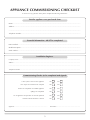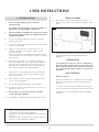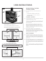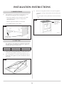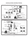
1
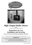
Yeoman CL
High Output Boiler Stove
YM-CL8HB
Instructions for Use,
Installation and Servicing
For use in GB & IE (Great Britain and Republic of Ireland).
This appliance has been certified for use in countries other than those stated. To install this appliance in these countries, it is essential to obtain the translated
instructions and in some cases the appliance will require modification. Contact Stovax for further information.
IMPORTANT
This appliance will become hot whilst in operation, it is therefore recommended that a suitable guard should be used for the
protection of young children, the elderly or infirm. Do not attempt to burn rubbish in this appliance.
Please read these Instructions carefully before installation or use.
Keep them in a safe place for future reference and when servicing the fire.
The commissioning sheet found on page 3 of these instructions should be completed by the Installer.
PM442 Issue 2 (October 2010)
CONTENTS
APPLIANCE COMMISSIONING CHECKLIST 3
COMMISSIONING
31
USER INSTRUCTIONS
MAINTENANCE & SERVICING
32
General Points
Using the Appliance for the first time
Recommended Fuels
Lighting the Appliance
Running the Appliance
Burning Tips
Ash Removal
Woodburning
Extended Burning
Over-Firing
Chimney Fire General Cleaning
Cleaning Glass
Chimney Sweeping
Care of Stove
Seasonal Use
Troubleshooting Tips
4
4
6
6
7
8
9
10
11
11
11
12
12
12
12
13
13
13
Annual Service
Removal of Log Guard
Removal of Baffle
Fitting a New Glass Door
Fitting a New Door Seal
Adjusting Door Catches & Hinges
32
33
33
33
34
35
SPARE PARTS
36
SERVICE RECORDS
38
INSTALLATION INSTRUCTIONS
TECHNICAL Technical Specifications
Standard Features
Packing List
Boiler Output Chart
Dimensions
15
15
15
15
15
16
SITE REQUIREMENTS
Flue & Chimney
Flue Exit Positions
Hearth Dimensions
Walls Next to Hearth
PRE-INSTALLATION
Flue
Ventilation
INSTALLATION
Legal Requirements
Installing the Appliance
Top Flue Installation
Rear Flue Installation
Removal of Log Guard
Fitting & Removal of Baffle
Removal of the Riddling Mechanism
Hearth Fixing
Fitting Cast Top
17
17
18
18
19
Warranty
20
Your Yeoman retailer provides you with a Two Year Warranty
for your new stove. However, this specifically excludes
naturally wearing parts or ‘consumables’ such glass, firebricks
and rope seal and the use of non-authorized fuel such as
petro-cokes. Furthermore, for the warranty to be valid,
your stove must have been installed in accordance with the
manufacturer’s instructions and the second year’s warranty is
dependent on the appliance being serviced 12 months after
installation by a HETAS or other similarly qualified engineer.
20
21
22
22
22
22
22
23
24
24
26
26
They also provide a Five Year Casting Warranty for the carcass
of all cast iron stoves and the cast iron door of steel stoves.
Again, this excludes naturally wearing cast parts such as grate,
dampers, log retainers and baffles.
You can help your retailer to provide their warranties by
returning the reply card or registering online at
www.yeoman-stoves.co.uk
2
APPLIANCE COMMISSIONING CHECKLIST
To assist us in any guarantee claim please complete the following information:-
Retailer appliance was purchased from
Name:..................................................................................................................................................................
Address:................................................................................................................................................................
. ...........................................................................................................................................................................
Telephone number:..............................................................................................................................................
Essential Information - MUST be completed
Date installed:......................................................................................................................................................
Model Description:...............................................................................................................................................
Serial number:......................................................................................................................................................
Installation Engineer
Company name:......................................................................................................................................................................
Address:..................................................................................................................................................................................
...............................................................................................................................................................................................
Telephone number:.................................................................................................................................................................
Commissioning Checks (to be completed and signed)
Is flue system correct for the appliance
YES
NO
Flue swept and soundness test complete
YES
NO
Smoke test completed on installed appliance
YES
NO
Spillage test completed
YES
NO
Use of appliance and operation of controls explained
YES
NO
Instruction book handed to customer
YES
NO
Signature:........................................................................................
3
Print name:................................................................
USER INSTRUCTIONS
SERIAL NUMBER
1. General POINTS
1.1
Before use of this appliance please read these
instructions fully.
The appliance must be fitted by a registered installer*, or
approved by your local building control officer.
1.2
Only use for domestic heating in accordance with these
operating instructions.
1.4
You must burn only approved fuels. Do not use with liquid
fuels or as an incinerator.
1.5
Appliance surfaces become very hot when in use. Use
a suitable fireguard if young children, elderly or infirm
persons are present.
Stovax offer firescreens, sparkguards and hearthgate systems
for protection‡. Your Yeoman retailer can advise you about
these products.
1.6
1
All local regulations, including those referring to national
and European Standards need to be complied with when
installing the appliance.
1.3
1.13 This number is required when ordering spare parts or
making warranty claims. It is found on the appliance data
plate.
Data Plate
PR8745
THERMOSTAT
Do not place photographs, TV’s, paintings, porcelain or
other combustible items on the wall or near the appliance.
Exposure to hot temperatures will cause damage. Do not
place furniture, or other items such as drying clothing,
closer than 1m from the front of this appliance.
1.7
Extractor fans or cooker hoods must not be placed in the
same room or space as this can cause appliance to emit
fumes into the room.
1.8
Do not obstruct inside or outside ventilation required for
the safe use of this appliance.
1.9
Do not make unauthorised changes to the appliance.
The data plate is found on a swing out data plate located
on the back of the stove on the left hand side (see
Diagram 1).
As an optional extra this stove can be controlled by a
thermostat which regulates the rate at which the fuel is
burned and the amount of heat produced. A trial and
error approach will establish settings to suit personal
preference.
AIR CONTROLS
Double Air Systems
This Yeoman appliance has a double air system, providing
cleaner burning and greater efficiency and control (see
Diagram 2).
1.10 The chimney must be swept at least once a year (see User
Instructions, Section 14).
1) Airwash - air drawn over the window cleans the glass. The source of Primary Combustion air when burning wood.
1.11 Do not connect, or share, the same flue or chimney
system with another appliance.
2) Primary Air - for use with solid fuel and when lighting
wood fires.
1.12 This appliance is designed to be used with the doors shut.
‡In the U.K. these products must conform to BS 6539,
Fireguards for use with solid fuel appliances.
If appliance is operating unattended they must conform to
BS 3248
*Registered on the Competent Persons Scheme (GB only)
see page 35 / INFO (Republic of Ireland).
4
USER INSTRUCTIONS
2
HEATING SYSTEM controls
CONTROLS, GENERAL
1.18 The controls fitted to the system will provide two
functions:
—To control the comfort level in the house.
—To maintain safety in the event of misuse or COMFORT CONTROLS
mechanical failure.
1.19 A programmable timer switches the pump on when heat
is required and off when it is not.
The timer, when combined with a room thermostat and
/ or thermostatic radiator valves, enhances the comfort
levels in the house.
Some room thermostats combine the function with
the timer and can be programmed to reduce the room
temperature rather than turning the system off. This is
effective in not allowing rooms to become too cold and
speeding up recovery time.
PR8857
For Air Controls see the diagram over.
Use the tool provided to operate the air controls.
Do not place tool on hot surfaces (e.g. top of stove).
CLOSE
Airwash Control
1.20 The hot water cylinder can also be fitted with a
thermostatic valve which turns off the flow when the
cylinder has reached the desired temperature, but the
heat leak radiator will have to be bigger to cope with the
extra load when the tank is isolated.
OPEN
PR8932
CLOSE
Primary Control
1.21 A high limit thermostat is fitted to the gravity flow pipe
set at 80˚C. This thermostat should be connected to the
pump so that the pump is turned on if the temperature
exceeds 80˚C. This will prevent accidental boiling in the
gravity circuit.
PR8934
1.22 It is also recommended to fit a low limit thermostat on
the central heating return set at 45˚C. This thermostat will
turn the pump off if the return temperature falls below
45C. This will prevent corrosion and condensation within
the stove.
OPEN
DOOR OPERATION
1.14 Use a protected gloved hand to operate.
DO NOT OPEN THE DOOR WITH BARE HANDS
To Open and Close
Rotate handle and pull door to open
PR8935
SAFETY CONTROLS
PR8936
5
NOTE – Further information on solid fuel central heating systems can be found in the HETAS engineers training
manual.
USER INSTRUCTIONS
WARNING
Properly installed, operated and maintained this
appliance will not emit fumes into the room.
2.6
Precautions must be taken to ensure that this build up of
condensate does not overflow from the appliance onto
any surrounding fabric of the room e.g. carpets.
NOTE - THIS CONDENSATION IS NORMAL DURING
FILLING AND DOES NOT INDICATE A FAULTY OR
LEAKING STOVE.
NORMAL RUNNING
2.7
During normal running this condensation should be
minimal if the system is fitted with the low limit thermostat
as detailed in 1.22 (above). This low limit thermostat
prevents the system pump from running until the stove has
reached temperature.
Occasional fumes from de-ashing and refuelling may occur.
Persistent fume emission is potentially dangerous and
must not be tolerated.
If fume emission does persist:
—Open doors and windows to ventilate the room.
—Allow fire to burn out and safely dispose of fuel from the
appliance.
SEASONAL USE
—Check for chimney blockage and clean if required.
2.8
—Do not attempt to relight until the cause of the emission has been identified and corrected. If necessary seek expert advice.
If this appliance is unused for lengthy periods of
time it should be periodically checked to ensure that
condensation is not building up within the stove.
NOTE – THIS CONDENSATION IS NORMAL AND DOES
NOT INDICATE A FAULTY OR LEAKING STOVE.
If the stove is going to be unused for very long periods of
time it is recommended to drain the system.
All open flued appliances can be affected by temporary
atmospheric conditions which may allow fumes to enter
the house. Because of this it is recommended that an
electronic carbon monoxide detector conforming to
BSEN50291 be fitted and maintained.
3. RECOMMENDED FUELS
2. USING THE Appliance FOR THE FIRST
TIME
2.1
3.1
Wood Logs
Burn only seasoned timber with a moisture content of less
than 20%. To ensure this allow cut wood to dry for 12 to
18 months.
To allow the appliance to settle and fixing glues and paint
to fully cure:
—Operate the appliance at a low temperature for first 2.2
Do not touch the paint during the first period of use.
2.3
During this time the appliance may give off some
unpleasant odours:
3
few days.
Wood Length
—Keep the room well ventilated to avoid a build-up of CONDENSATION
Appliance
CAUTION WHEN FILLING
CL8
2.4
When filling the boiler with water for the first time,
the cold water entering the water jacket can cause
condensation to form on the surfaces of the appliance
(inside and outside).
2.5
fumes.
In certain conditions this condensation could result in a
considerable amount of water, in some cases enough to fill
the bottom of the appliance. This could be even worse if
the house has recently been re-decorated, wet plastered
or any other work has been undertaken which could result
in high humidity.
6
Wood Length
400mm
Poor quality timber:
—Causes low combustion efficiency.
—Produces harmful condensation.
—Reduces effectiveness of the airwash and life of the appliance.
Do not burn construction timber, painted, impregnated
/ treated wood, manufactured board products or pallet
wood.
USER INSTRUCTIONS
3.2
Solid fuel
Burn only anthracite or manufactured briquette smokeless
fuels listed as suitable for use with closed heating
appliances.
5
Do not burn bituminous coal, ‘petro-coke’ or other
petroleum based fuels as this will invalidate the product
guarantee.
3.3
Fuel consumption
Fuel Consumption
Description
Yeoman CL 8HB
3.4
Kg/hour
Wood
Kg/hour
Briquette
Smokeless fuel
4.8
2.1
For advice on suitable solid fuels contact your local
approved coal merchant*.
A number of factors can affect the performance of the
appliance (see User Instructions, Section 6).
—Leave the door slightly open as the fire establishes and the glass warms to avoid the build-up of condensation.
—Add larger pieces of wood. Too many logs may smother the fire.
Do not load fuel above the log guard and the base of the
baffle at the back of the firebox (see
Diagram 6).
6
4. Lighting the Appliance
4.1
For best results:
—Set air controls (see Diagram 4).
4
Airwash: Fully Open
Primary Air: Fully Open
Base
of
baffle
Log Guard
—Close the door.
*In the U.K.
Ring the Solid Fuel Association advice line on
0845 601 4406 for details or visit their web site at
www.solidfuel.co.uk
PR8934
—Place firelighters or paper and dry kindling wood on the grate.
—Light the paper or firelighters (see Diagram 5).
7
PR8936
USER INSTRUCTIONS
—Rake the embers evenly over the firebed and open the 5. Running The appliance
Airwash control fully for a few minutes before re-fuelling.
Burning wood:
Do not refuel when a large amount of flames are
present in the firebox as this could cause smoke or
flames to spill into the room.
convection and radiation.
Close the doors immediately after refuelling.
—Hot water to heat radiators and domestic hot water. 5.3
Burn new logs at a high temperature for a few minutes
before adjusting the Airwash control. Refuel little and
often for clean, efficient burning.
Do not load above the log guard or base of baffle.
5.4
Do not burn large amounts of fuel with the Airwash
control closed for long periods of time. This reduces the
glass cleaning effect of the Airwash and causes tars and
creosotes to build-up in the appliance and flue system.
5.5
When in use, running the appliance at a high temperature
for a short period reduces tars and creosotes.
5.6
Experience establishes settings to suit personal preference.
Do not burn construction timber, painted,
impregnated / treated wood, manufactured board
products or pallet wood.
5.6
Burning Solid Fuel
To burn smokeless fuels a cast iron multi-fuel grate must
be fitted.
Only for use with recommended fuels (see User
Instructions, Section 3). 5.7
Set air controls as shown in Diagram 9.
5.1
This appliance gives out its heat in two ways:
—Directly into the room in which it is fitted through The output to hot water varies depending on how quickly the fuel is being burnt. Fore more detail see the graph on page 13.
5.2
Only for use with recommended fuels, see Section 3 for
full details.
—Close the Primary Air control and use the Airwash to control the burn rate when the appliance is at optimum operating temperature (see Diagrams 7 & 8).
7
9
PR8012
8
Airwash
Airwash: Adjust
PR8937
—Wood burns best on a bed of ash (approx. 25mm (1") deep).
Primary Air
PR8933
8
USER INSTRUCTIONS
5.8
De-ash the firebed before re-fuelling (see User
Instructions, Section 7).
6. Burning tips
Open the Primary Air Control fully to establish a glowing
bed before adding new fuel.
Burn new fuel at a high temperature (see Diagram 7) for a
few minutes before adjusting the Primary Air Control to
the desired setting.
Refuel little and often for clean, efficient burning.
5.9
Experience establishes settings to suit personal preference.
5.10 Do not burn large amounts of fuel with the Primary Air
Control on a low combustion setting for long periods of
time. This reduces the glass cleaning effect of the Airwash
and causes tars and creosotes to build-up in the appliance
and flue system.
5.11 When in use, burning the appliance at a high temperature
for a short period reduces tars and creosotes.
6.1
Fuel Quality (Wood)
Use wood with a moisture content of less than 20%.
Seasoned logs have the bark beginning to lift and peel away
and cracks radiating from the centre. They feel lighter than
fresh cut wood of a similar size and sound hollow when
struck against each other. Logs should not feel damp or
have moss and fungal growths.
Symptoms related to wet wood:
—Difficulty starting and keeping a fire burning well.
—Smoke and small flames.
—Dirty glass.
—Rapid creosote build-up in the chimney.
—Low heat output.
—Short burn times, excessive fuel consumption and
blue/grey smoke from the chimney.
Burn at a high temperature for a short period each day
to avoid large build-ups of tars and creosote within the
appliance and the flue system.
Use Stovax Protector chimney cleaner to reduce this
problem.
6.2
Fuel Quality (Solid Fuel)
Use recommended solid fuels approved for use with closed
appliances.
Symptoms related to unsuitable fuels include:
—Difficulty starting and keeping a fire burning well.
—Smoke and small flames.
—Dirty glass and/or fire bricks.
—Short life span for Grate and Baffle.
—Permanent staining of glass.
6.3
Air inlets puffing smoke
Combustion gases can build up in the firebox and ignite
as small explosions, causing smoke to puff out of the air
inlets and other openings. This occurs if the air controls
are shut soon after adding new fuel to a very hot fire. Stop
by opening the air controls to increase combustion air and
burning rate.
6.4
Flue Draught
The chimney has two main functions:
1) To safely remove the smoke, gases and fumes from the
house.
2) To provide a sufficient amount of draught (suction) in the
appliance ensuring the fire keeps burning.
5.12 Only anthracite or smokeless fuels suitable for use in
closed appliances must be burned in this appliance.
5.13 Do not burn bituminous coal, ‘petro-coke’ or other
petroleum based fuels as this invalidates the product
guarantee.
5.14 Do not load fuel above the log guard and the base of
the baffle at the back of the firebox (see Diagram 5).
REFUELLING
5.15 De-ash the fire bed before refuelling, see Ash Removal
—Open the Primary air control fully to establish a —Do not refuel when a large amount of flame is —Close the doors immediately after refuelling.
glowing bed before adding new fuel.
present in the firebox as this could cause smoke or flames to spill into the room.
—Burn new fuel at a high temperature for a few minutes before adjusting the Primary air control to the desired setting.
—Refuel little and often for clean, efficient burning.
5.16 Do not re-fuel the stove above the level of the log guard
or the base of the baffle.
THERMOSTAT OPERATION
5.17 This appliance can be fitted with a thermostat kit to
control the temperature of the boiler. See the instructions
included in the kit for operation details.
9
In the U.K.
* Registered on the Competent Persons Scheme (GB only)
see page 35 / INFO (Republic of Ireland).
** This should be done by a HETAS registered chimney
sweep, see page 35, who will issue you with a certificate.
USER INSTRUCTIONS
Draught is caused by the rising hot air in the chimney when
the appliance is lit.
Symptoms of poor performance related to flue draught
include:
—Excessive fuel consumption (high flue draught).
—Poor burning control, overheating (high flue draught).
—Wind noise from air controls (high flue draught).
—Difficulty getting a fire going and keeping it burning well
(low flue draught).
—Low heat output (low flue draught).
—Smoke entering room when doors opened (low flue
draught).
The construction, position, size and height of the chimney
all affect the performance of the flue draught.
Other factors effecting the flue draught include:
—Trees or other buildings nearby causing turbulence.
—Outside temperature.
—Outside weather conditions.
—Incorrect additional ventilation to building.
—Blocked flue / chimney.
For advice on the correction of persistent flue problems
consult a qualified solid fuel heating engineer before
continuing to use the appliance.
6.5
Weather conditions
The weather conditions outside the building can effect the
burning performance of the appliance. These could include:
Weather Conditions
Problem
Effect
Windy days
Buildings/Obstacles
cause turbulent air
around chimney.
Smoky Appliance
Calm days
Oversized Chimney.
Smoky Appliance
Damp / Rainy days
Flue temperature
not hot enough.
Rain water inside
chimney.
Lighting and
burning problems
To reduce these problems:
—Use good quality kindling wood to start the fire.
—Burn initially at a high temperature for a short period.
—Fit a rain cowl to the chimney.
Your installer should advise you on possible solutions.
If the appliance emits smoke into the room continuously:
—Close the air controls and allow the appliance to go out.
—Ventilate the room to clear the fumes.
Do not re-light the appliance until the problem is solved.
7. ASH REMOVAL
7.1
Multi-fuel stove
Riddle with the tool provided (see Diagram 10).
10
Rotate to
operate
PR8861
Open Door (see Diagram 11).
11
PR8729
—Using gloves carefully remove ashpan with the tool provided. Heat can remain long after use.
—Place the ash into a Stovax Ash Caddy (Stovax Part No. 4227) or other suitable container.
—Remove ash at least once every week when burning wood.
10
—Do not place hot ash in a container made from plastic or any other combustible material.
USER INSTRUCTIONS
8.1
—Fit the plug supplied into the hole where the riddling 8. Wood burning tray
In order to burn wood continuously in this appliance a
Wood Burning Tray should be fitted (see Diagram 12).
mechanism is normally located and secure with bolt and clamp (also supplied, see Diagram 15).
15
12
Clamp
Plug
Bolt
Front edge
PR8865
PR8862
—Replace the log bar.
8.2
Remove the multi-fuel grate from the appliance (see
Installation Instructions, Section 5).
8.2
To fit the Wood Burning Tray:
—Remove the log bar.
—Hold the tray flat with the front edge pointing forwards (see Diagram 12).
—Tilt diagonally and insert through the front of the stove 9. Extended burning
9.1
(see Diagram 13).
13
It is possible to get the appliance to burn for extended
periods of time. In order to do this:
—De-ash prior to final refuelling.
—Set air controls to low combustion settings.
This will gradually blacken the glass but it will clear when
operated at a high temperature for a short period.
—Use smokeless fuel or small, thick logs.
10. OVER-FIRING
10.1 Do not over-fill with fuel or run at high temperatures for
long periods or over-firing can occur. If the flue pipe, flue
collar or top plate glow red the appliance is over-firing.
Close the air controls to reduce the temperature.
10.2 Over-firing can cause permanent damage to the
appliance.
PR8863
—Place tray flat on the fixings on the firebed (see
Diagram 14).
14
PR8864
11
USER INSTRUCTIONS
11. Chimney fire
Check that the door shuts properly and creates an effective
seal. Leaking door seals prevent the appliance working
properly.
Do not use aerosol sprays near an operating appliance.
11.1 If a chimney fire occurs:
—Shut all air controls immediately.
—Evacuate the building.
—Call the fire brigade.
—Do not re-enter the building until it is confirmed safe.
13. CLEANING GLASS
13.1 Sometimes additional cleaning may be required.
11.2 Do not use the appliance after a chimney fire until:
a) It has been inspected by a registered installer*,
confirming the appliance is safe to use.
b) The chimney system has been inspected and swept by a
chimney sweep, confirming the system is structurally sound
and free from obstruction**.
This can be done as follows:
—Allow appliance to cool fully. Do not clean hot glass.
—Use a soft cloth and Stovax Glass Cleaner.
13.2 Before re-lighting the appliance dry the glass fully.
c) It is repaired as required before re-use. Use only
genuine Yeoman replacement parts to keep your appliance
in safe, efficient working order.
13.3 Do not use abrasive cleaner or cleaning pads.
14. CHIMNEY SWEEPING
12. GENERAL CLEANING
14.1 To maintain safe and efficient use of the appliance, the
chimney/flue must be inspected and swept at least once a
year by a qualified chimney sweep**.
12.1 Clean and inspect the appliance regularly, especially in
periods of heavy use. Regular cleaning and maintenance
will help give many years of safe use.
Allow appliance to cool thoroughly to avoid risk of burns.
Clean regularly, according to level of use.
Remove the ash completely (see User Instructions,
Section 7).
Check the internal components for damage. Do not use
the appliance if any parts are broken or damaged. Replace
damaged parts with genuine Yeoman replacement parts to
keep the appliance in safe, efficient working order.
Check for obvious build up of soot, ash or debris above the
flue baffle(s) (these can be found in the upper part of the
firebox). Use a torch if necessary.
If there are any signs of a build up of debris above the flue
baffle(s) either:
—Arrange for the chimney to be swept (see User —Remove the baffle and clear the debris (see Installation Keep the glass clean with correct use of the Airwash system
and good quality fuel.
If the appliance is used continuously throughout the year,
or it is used to burn wood or smokeless fuel, more frequent
sweeping is recommended.
The best time to have the chimney swept is at the start of
the heating season.
The above applies even if burning smokeless fuels.
14.2 The chimney, any connecting flue pipe and the appliance
flue ways, if incorporated, must be regularly cleaned.
14.3 Ensure adequate access for cleaning where it is not possible
to sweep through the chimney.
14.4 If the chimney is believed to have previously served an
open fire it must be swept a second time within a month of
regular use after installation.
Instructions, Section 14).
Instructions, Section 3).
To refresh painted finishes use Stovax Riva Midnight black
metallic paint.
Wipe dry with a soft clean cloth be fore relighting. Always
dry appliance to avoid rust.
Do not use abrasive cleaner or cleaning pads.
12
In the U.K.
* Registered on the Competent Persons Scheme (GB only)
see page 35 / INFO (Republic of Ireland).
** This should be done by a HETAS registered chimney
sweep, see page 35, who will issue you with a certificate.
USER INSTRUCTIONS
15. Care of stove
Stovax has a range of cleaning and maintenance products
and accessories to keep your appliance in good working
order. Your Yeoman retailer can advise you on suitable
items for your stove and provide genuine spare parts
such as replacement glass and door sealing rope. View
the extensive range at www.stovax.com by clicking on
Accessories. In addition, an annual service by a competent
engineer is recommended to keep your stove in the best
possible condition.
4.
130°C - 250°C (270°F - 480°F). Failing to close down the
Primary Air Control once the appliance has heated up to
this range may cause the appliance to exceed the ideal
temperature range and to over-fire. Over-firing can cause
permanent damage to the appliance and invalidates your
warranty. Burn with the Airwash Control fully open for
approximately 20 minutes to cure this.
The problem may be caused by damping down the
appliance during periods of extended burning.
Problems with the flue, in particular insufficient air pull.
If the flue is not working efficiently the glass can blacken.
A flue which has too much downdraft may be too short,
needs lining, or has too many bends. This can also cause
blackening of the stove glass. Contact the installer or a flue
specialist for advice.
17.2 Riddling Mechanism Jamming
This occurs when ash builds up under the riddling grate
preventing movement. To rectify:
16. Seasonal use
16.1 Clean and service the appliance if it is not used during the
warmer periods of the year, as detailed in the Maintenance
and Servicing section.
16.3 Before re-lighting the appliance:
—Remove the baffle.
—Clear any debris that may have accumulated.
—Check the flue is clear of any blockages.
—Lift out the riddling mechanism (see Installation
—Replace riddling mechanism when cleaning is complete.
—De-ash and clean the inside of the appliance regularly
Instructions, Section 5) and remove all ash.
to avoid build up of ash and subsequent jamming of
mechanism.
17.3 Glass cracking
Do not over tighten the screws on the glass clips when
replacing the glass. This causes stress and the intense
temperature changes can cause the glass to crack. For
replacement glass contact your local Yeoman retailer.
16.2 Set the air controls to 50% to keep the appliance ventilated
and stop the build-up of any moisture inside.
17.4 Appliance is producing tar
17. Troubleshooting tips
This can be identified by:
—A very strong pungent smell shortly after the appliance is lit and heats up.
—Glass blackening.
—Thick, brown, sticky tar oozing from the pipe joints.
17.1 Stove glass blackening
This has four possible causes:
This is caused by burning damp wood and running the
appliance at too low a temperature.
1.
Incorrect use of Airwash
See User Instructions, Sections 1, 4 and 5 for the correct use
of the air controls.
Use well seasoned wood and operate the appliance within
the ideal temperature range.
2.
Burning unseasoned wood
See User Instructions, Section 3 to identify when wood is
ready for burning.
Tar is a major cause of chimney fires. If the appliance
experiences problems with tar build up consult a chimney
sweep before continued use of the appliance.
3.
Stove operated at too low a temperature
A stove pipe thermometer can identify this problem (Stovax
part no 3046). The ideal working temperature range is
13
USER INSTRUCTIONS
17.5 All or some of the radiators do not get hot
Open up the airwash to make
a hotter fire
Burning wood
Wood is burning too
slowly
If fitted set the thermostat to a
higher setting
Burn dryer wood
Burn better quality wood
Reduce ashbed to 1" thick
Burning Solid
Mineral fuels
Fuel is burning too
slowly
Open up the primary air to
make a hotter fire. If fitted,
set the thermostat to a higher
setting
The fire needs riddling to
remove ash. De-ash the fire
Empty the ash pan.
All Fuels
Stove is not producing
much heat.
System faults
Not enough fuel.
Bleed the radiators to ensure
there are no air locks.
Incorrect system design seek
professional assistance
Too many radiators in the
system exceeding the stoves
capabilities.
17.6 In the unlikely event of a problem that cannot be solved
by these tips contact your installer or retailer for help.
14
TECHNICAL SPECIFICATION
YEOMAN
Model
Yeoman YM-CL8HB
Nominal Heat Output
Flue Draft at Nominal Heat Output
Wood
kW
8
Solid Fuel
kW
8.6
mm Wg
1.25
inch Wg
0.05
mm
150
inch
6
All Fuels
Flue Outlet Size (Top or Rear Option)
Minimum Hearth Type Required
Constructional = CH
CH
kg
140
Weight
Wood
Recommended Fuels
Solid Fuels
Primary Air (under grate air for full multi-fuel use).
•
Airwash (for wood burning / clean glass).
•
Riddling grate system for clean de-ashing.
•
Top or rear flue exit option.
Briquette smokeless fuel suitable
for closed appliances.
(Ancit - Phurnacite - Taybrite Homefire ovals)
Boiler Output Chart
1. STANDARD FEATURES
•
Seasoned wood (less than 20%
moisture content)
2. PACKING LIST
•
User & Installer Instructions
•
Guarantee card
•
Pair leather gloves
•
Ashpan
•
Ashpan tool
•
Riddling tool
PR8233
15
TECHNICAL SPECIFICATION
YEOMAN DIMENSIONS
C
A
D
E
M
G
B
K
N
F
J
L
PR8852
Cast Top Plate
H
PR8753
incl. feet @ 6mm on underside
Description
A
B
C
D
E
F (Ø)
G
H
J
K
L
M
N
Yeoman
YM-CL8HB
563
572
363
105
478
153/6"
449
24
441
225
430
224
317
All dimensions are in mm (25.4mm = 1")
16
SITE REQUIREMENTS
1. FLUE OR CHIMNEY
1.1
The flue or chimney system must be in good condition.
It must be inspected by a competent person and passed for
use with the appliance before installation.
Products of combustion entering the room can cause
serious health risks.
1.2
The following must be checked:
—The construction of the masonry chimneys, flue block —A flexible flue liner system can be used if certified for 1.4
Suitable access must be provided to enable the collection
and removal of debris.
1.5
The flue must be swept and inspected when the appliance
is installed.
1.6
The flue draught must be checked with all windows and
doors closed and any extraction fans in this, or adjoining
rooms, running at maximum speed (see next section for
additional ventilation requirements).
Max. Draught = 2.0mm Wg
Min. Draught = 1.0mm Wg
chimneys and connecting flue pipe system must meet the requirements of the Building Regulations†.
use with solid fuel systems and installation complies with manufacturer’s instructions and Building Regulations†.
The flue liner must be replaced when an appliance is replaced, unless proven to be recently installed and in good condition.
—If it is necessary to fit a register plate it must conform to
—The minimum height of the flue or chimney must the Building Regulations†.
be 4.5m from the hearth to the top of the flue, with no horizontal sections and a maximum of 4 bends.
Bends must have angles of less than 45 degrees from the vertical.
—Ensure the connecting flue pipe is kept a suitable —Make provision to remove the appliance without the distance from any combustible material and does not form part of the supporting structure of the building.
**This should be done by a HETAS Approved Chimney
Sweep (UK only) see page 27 / INFO registered (Republic
of Ireland only) who will issue you with a certificate.
† Building Regulations Document J
Flue Plate:
Where a hearth, fireplace, flue or chimney is provided or
extended (including cases where a flue is provided as part of refurbishment work), information essential to the
correct appliance and use of these should be permanently
posted in the building, to meet Requirement J4 of the
Building Regulations (England and Wales), F3.12 (Scotland).
Additional:
A new factory made system that complies to EN 1856; Part 1
can be used providing installation is to the requirements of:
i) BS 7566 Parts 1 -4
ii) the manufacturer's instructions
iii) Building Regulations.
For a guide containing information on Chimneys and Flues contact: The British Flue & Chimney Manufacturers’ Association,
FETA
2 Waltham Court
Milley Lane
Hare Hatch
Reading
Berkshire RG10 9TH
Tel: 0118 9403416
need to dismantle the chimney.
—Any existing flue must be confirmed as suitable for
the new intended use as defined in the Building Regulations†.
—The flue or chimney systems must be inspected and swept to confirm the system is structurally sound and free from obstructions**.
—If the chimney is believed to have previously served
an open fire it must be swept a second time within
a month of regular use after installation to clear any soot falls that may have occurred due to difference in combustion levels.
—The flue exit from the building must comply with local —Do not connect or share the flue or chimney system 1.3
building control rules†.
with another heating appliance.
Do not connect to systems containing large voids or spaces
over 230mm square.
17
In the U.K.
*The design of the flue and chimney systems and products
used should meet the requirements of ADJ along with any
other relevant, National or European standards that may
apply. Products should be specified with regard to the type
of appliance, position within the building, fuels to be used
and appliance operating temperatures.
e-mail: [email protected]
SITE REQUIREMENTS
1. FLUE OUTLET POSITIONS
Terminal
Flue
Vertical
Measurement
Horizontal
Measurement
150mm
max
Insulation
Adjacent
Building
The vertical measurement is the lowest from either the
point of discharge or 150mm above insulation.
IMPORTANT: Seek specialist
advice if installing in a dwelling
with a thatched roof
Position On Roof
Minimum Clearances
A
On ridge or within 600mm
600mm above ridge
B
Elsewhere on roof
2300mm horizontally from roof surface and:
a) 1000mm above highest point of flue exit
from roof or
b) as high as the ridge
C
On pitched, within 2300mm horizontally to
openable window, dormer
1000mm above top of opening
D
Within 2300mm of another building
600mm above top of building
1. HEARTH DIMENSIONS
150mm
minimum
225mm
minimum
Constructional Hearth
840mm minimum
150mm
minimum
150mm
minimum
Constructional Hearth
840mm minimum
2.1
The appliance must stand on a non-combustible
constructional hearth which is at least 125mm thick with
the minimum dimensions as shown in diagram.
2.2
If this appliance can be installed in an elevated setting it
is recommended to increase the 225mm hearth depth to
safely contain any falling logs or embers. The higher the
appliance is installed the deeper the hearth should be to
avoid scorched floor coverings.
2.3
The building must have a suitable load-bearing capacity for
the hearth and appliance. Consult a structural engineer
for advice before proceeding.
2.4
When fitting into an existing hearth check that the hearth
complies with current construction regulations and is at least
the minimum sizes shown.
2.5
If there is no existing fireplace or chimney it is possible to
construct a suitable non-combustible housing and hearth
setting. The flue must be installed in accordance with all
local and national regulations and current rules in force.
Check if adding a new chimney to your property requires
planning permission.
PR8730
18
SITE REQUIREMENTS
WALLS NEXT TO A HEARTH
Solid, non-combustible
material e.g. masonry or
concrete
Thickness W
H
150mm
minimum
C
150mm
minimum
C
PR8731
Position of Appliance & Hearth in relation to walls
Requirement for the walls
Distance of hearth from wall
'C'
Distance of Appliance to wall
Min thickness of Wall
'W'
Min height of wall
'H'
0mm
0mm - 50mm
200mm
0mm
51mm - 300mm
75mm
Height of appliance + 300mm
Or
1200mm from the hearth (take largest
dimension)
0 - 150mm
150mm +
75mm
1200mm
150mm +
300mm +
No Minimum Requirement
Suitable clearance should be allowed around the stove to enable the correct fitting and maintenance of the appliance.
Any clearances should be confirmed by making a site survey and a physical check of wall thickness and dimensions.
Note:
When installing a Multi-fuel appliance a
minimum gap of 80mm must be left on the
Right Hand Side so that the riddling tool
can be comfortably engaged in the socket.
80mm
PR8589
19
PRE-INSTALLATION CHECKS
1. Flue
Model
Yeoman YM-CL8HB
Without Liner System
Round (diameter)
Flue / Chimney Size
Without Liner System (square)
Minimum Dimension
With Liner or Factory Made
System (diameter)
Flue / Chimney
minimum height*
mm
150
inch
6
mm
135
inch
5½
mm
150
mm
6
m
4.5
feet
15
*When measured from the top of the flue, with no horizontal sections and a maximum of 4 bends with angles of
less than 45°
20
PRE-INSTALLATION CHECKS
2. VENTILATION
2.1
Additional ventilation will be required to suit the
requirements of Building Regulations. This must be provided
using a permanently open air vent, of the size listed, which
is positioned so that it is not liable to be blocked both inside
and outside the building.
2.2
The appliance will require additional ventilation as listed*:
A) Building design permeability greater than 5.0m³ (h.m²).
B) Building design permeability less than 5.0m³ (h.m²).
Model
YM-CL8HB
A
B
Additional Ventilation
Additional Ventilation
mm²
4400
cm²
44.00
in²
7.10
mm²
7150
cm²
71.50
in²
11.54
2.6
Extractor fans or cooker hoods must not be placed in the
same room or space as this can cause the appliance to emit
fumes into the room.
2.7
Increase air supply provisions where a room contains multiple
appliances.
2.8
The need for additional ventilation may also be identified
during the commissioning procedure and should be provided
if needed.
2.3
Permanent air vents should be non-adjustable and positioned
where they are unlikely to be become blocked.
2.4
If vents open into adjoining rooms or spaces there must be an
air vent of at least the same size direct to the outside.
An inadequate air supply to the room is potentially
dangerous.
2.5
Site the vents where cold draught is unlikely to cause
discomfort. This can be avoided by placing vents near ceilings
or close to the appliance, see diagram.
2.9
If any checks reveal problems do not proceed with the
fitting of the appliance until they have been rectified.
* Changes to Document J, England & Wales, from 01/10/2010
21
INSTALLATION INSTRUCTIONS
Legal requirements
Before installation and/or use of this appliance please
read these instructions carefully to ensure that all
requirements are fully understood.
The appliance must be fitted by a registered installer*,
or approved by your local building control officer.
It is very important to understand the requirements of the
national Building Regulations† and standards‡, along with
any local regulations and working practices that may apply.
Should any conflict occur between these instructions and
these regulations then the regulations must apply.
Your local Building Control Office can advise regarding the
requirements of the regulations.
The appliance must be fitted by a registered installer* or
approved by your local building control officer.
Works must be carried out with care to meet the
requirements of Health and Safety** and comply with
the Health and Safety rules**, and any new regulations
introduced during the lifetime of these instructions.
Particular attention should be drawn to:
Choose top or rear flue exit (see Diagram 1).
Top
—Handling: The appliance is heavy. Adequate facilities Hexagonal Nuts
& Washers
PR8007
Rear
PR8732
—Fit flue collar and blanking plate to suit.
—Attach flue collar to top or rear with hexagonal bolts (see Diagram 1).
—Seal with fire cement.
—Secure blanking plate with hexagonal bolts
(see Diagram 2).
Hexagonal Nuts
& Washer
A faulty installation can cause danger to the inhabitants
and structure of the building.
PR8732
For users of this appliance:
Your building insurance company may require you to
inform them that a new heating appliance has been
installed on your property. Check that your cover is still
valid after installing the appliance.
1. INSTALLING THE Appliance
Take care when installing the appliance. Careless
handling and use of tools can damage the finish and/or
area.
Hexagonal Bolts
must be available for loading, unloading and on site handling.
—Fire Cement: Some fire cement is caustic and must not come into contact with the skin. Protective gloves
must be worn. Wash hands thoroughly with plenty of water after contact with skin.
—Asbestos: This appliance contains no asbestos. If there is the possibility of disturbing any asbestos in the
course of installation seek specialist guidance and use appropriate equipment.
—Metal Parts: Take care when installing or servicing the stove to avoid personal injury.
1.1
Each installation is unique to the property so it is not
possible to give details to suit every setting. The installation
must comply with Building Regulations† and be made using
best practice construction methods.
1.2
Top flue pipe installation:
—Lift appliance into position, taking care not to damage the hearth finish.
—Level the appliance.
—Connect appliance to the chimney using flue pipe.
—Secure with self tapping screw.
—Seal the connecting joints.
Many fireplace openings have a supporting lintel. Do not
remove without supporting the remaining structure of the
building. Do not support the structure with the appliance
or the flue system.
22
† England and Wales – Document J / Scotland - Part F/
Document J (Republic of Ireland only).
‡ BS 8303, BS 6461, BS 7566
*Registered on the Competent Persons Scheme (GB only)
see page 35 / INFO (Republic of Ireland).
**Health and Safety at Work Act 1974
INSTALLATION INSTRUCTIONS
—Secure with self tapping screw.
—Seal the connecting joints.
Do not use a 90˚elbow to make this connection.
The flue must be installed in accordance with manufacturers
instructions.
Seal Collar with Fire Cement
Self tapping screw
PR8009
Tee
The flue must be installed in accordance with
manufacturers instructions.
Flue Pipe 915mm (3ft)
Size
Stovax Part No.
6"
4602
Size
Stovax Part No.
6"
4616
Cap
PR8735
Self tapping
screw at rear
To chimney connection
as detailed in building
regulations
Seal flue collar
with Fire Cement
Elbow with access cover
PR8733
600mm min
1000mm max
unsupported
To chimney connection
as detailed in building
regulations
Size
Stovax Part No.
6"
4612
Stovax Part No.
6"
4602
Rear flue pipe installation:
—Insert a tee into the flue collar. The tee piece is used as cleaning access.
—Lift appliance into position, taking care not to damage the hearth finish.
—Level using adjustable bolts.
—Connect tee to the chimney using flue pipe.
Size
Stovax Part No.
6"
4602
2. REMOVAL OF THE LOG GUARD
PR8734
1.3
4612
PR8736
Flue Pipe 915mm (3ft)
Size
Stovax Part No.
6"
Flue Pipe 915mm (3ft)
Elbow with access cover
600mm min
1000mm max
unsupported
Size
23
2.1
To remove the Log guard:
—Lift Log Guard clear of the supporting brackets.
—Rotate to clear the sides of the door opening.
Do not use appliance without the log guard in position.
INSTALLATION INSTRUCTIONS
6
3. FITTING AND REMOVAL OF
THE BAFFLE
No tools are required.
3.1
To maintain efficient combustion the appliance is fitted with
a baffle system that allows for secondary combustion (see
Diagram 4).
Front
support
Rear
support
4
AR2405
Ensure baffle sits
on front supports
PR8885
3.2
First remove the log guard from the stove to give access to
the firebox.
3.3
Use both hands to lift the baffle vertically and slide to one
side (see Diagram 5). Always wear gloves when handling
appliance parts.
Do not modify the baffle.
4.1
The Multi-fuel grate can be removed for
cleaning to maintain good working
condition.
To remove the grate:
—Remove the baffle (see Section 3).
—Remove the log guard to enable access (see Section 2).
—Remove the ashpan.
—Remove the riddling bars (see Diagram 7).
AR2404
3.4
AR2406
4. REMOVAL OF RIDDLING MECHANISM
5
Baffle In Place
—Using both hands rotate the baffle to remove from the firebox through the door opening.
To replace the baffle repeat the above steps in reverse,
ensuring the baffle fits over the supports on the sides of the
interior (see Diagram 6).
24
FOR CLARITY, THE FOLLOWING DIAGRAMS DO NOT
INCLUDE ILLUSTRATIONS OF THE DOORS.
INSTALLATION INSTRUCTIONS
10
7
Lift bars to
remove
PR8875
PR8867
—Remove Rear Bar (see Diagram 8).
8
To remove Multi-fuel frames:
—Lift frames from the front.
—Remove right hand side first through the front of the —Repeat for the left hand side.
stove.
11
PR8868
To remove the Riddling Boss:
—Use the 5mm hex key as shown in Diagram 9.
PR8876
9
Fixing
Bolt
Riddling
Boss
—Unscrew the boss.
—Remove Riddling Cam Bar (see Diagram 10).
5mm
Hex Key
PR8870
25
—Replace in reverse order.
INSTALLATION INSTRUCTIONS
5. HEARTH FIXING
5.1
If the appliance is to be fixed to the hearth then use the
hearth mount locking tabs shown in Diagram 12.
—Position the appliance where required on the hearth and mark the location of the two fixing holes in the hearth mounts.
—Drill the required sized holes into the hearth.
—Use suitable fasteners to fix in place.
6.2
Place the cast top plate feet down on top of the appliance.
—Ensure the cast top is flush with the front and sides of the
appliance.
—For the top flue version, position the cutout over the flue ring.
14
Line up edges
of cast top
plate with the
appliance
12
PR8744
Fixing holes in
hearth mounts
PR8755
6. CAST TOP
This appliance can be fitted with an optional cast top plate.
The type of plate will depend on whether the appliance is
installed with a top* or rear flue exit.
Yeoman CL8
Top Flue
Rear Flue
YM-CL8CT
YM-CL8CTR
* The cast top must be fitted at the same time as the flue
connection (see Installation Instructions, Sections 1 & 6).
6.1
The cast top plate has 4 cast feet on the bottom to space it
off the top of the appliance by 6mm and allow the door to
open freely.
13
Cast feet
PR8756
26
INSTALLATION INSTRUCTIONS
3. Hot Water Cylinder
CENTRAL HEATING SYSTEM
1. General
This appliance gives out heat in two ways:
—Directly into the room in which it is fitted through —Hot water to heat radiators and domestic hot water.
convection and radiation.
3.1
The domestic hot water cylinder must be an indirect vented
double feed type to meet national standards** and should
have a minimum capacity of 117 litres. Houses with more
than one bathroom or a separate shower will need a bigger
tank.
Fully insulate the tank.
The water draw off pipes to the taps should be in a dead
leg connection from the vent pipe.
The installation must comply with building regulations and
use best practice advice.
4. Open Vent And Cold Feed System
2. Boiler Sizing
2.1
—Too big a boiler will run too hot and will not be efficient.
—Too small a boiler will not maintain the desired 2.2
Size the boiler correctly by calculating the following heat
loads:
RADIATORS - the amount of heat required to run the
radiators efficiently. The correct size of radiator depends
on the required temperature for the room, the room heat
losses and the radiator manufacturer’s guides.
The cold feed must be a minimum 22mm and enter the
system as the last connection on the common boiler return.
The open vent and cold feed must not be fitted with any
valves, manual or automatic.
Do not use plastic pipe in any part of the flow and
return.
temperature.
HOT WATER - the amount of heat required to provide the
desired amount of domestic hot water.
LOSSES – the amount of heat lost in pipe work - typically
10% of the combined radiators and hot water loads.
There are national guidelines for calculating these figures*.
Careful consideration must be given to where the appliance
is fitted. It must be sized correctly for the heat load required
and the size of the room. These requirements can be found
in the Technical Specifications.
2.4
This system must be fitted with a minimum of 22mm
diameter open vent discharging into a heat resisting feed
and expansion tank. There must be at least 25mm air gap
between the end of the pipe and the water level. The
cistern tank should have an overflow with a minimum
diameter of 22mm
It is very important to determine the correct size of
appliance for the house:
2.3
4.1
5. Heat Leak Radiator
5.1
All Stovax appliances are thermostatically controlled. The
burning rate is adjusted to the demands of the connected
heat load. If the radiators do not require heat then the
thermostat will act to shut down the appliance and the
direct heat output to the room where it is fitted will reduce
(see heat output graph on page 15 to show the ratio
between direct heat output and water heat output). To
prevent the room becoming too cold, fit a thermostatically
controlled radiator as well as the appliance.
27
A heat leak radiator must be fitted in the gravity circuit to
dissipate any excess heat produced from the boiler when
connected demand is low. The domestic hot water cylinder
may not be able to disperse heat at all times due to modern
insulation. This radiator is commonly fitted in the bathroom
and should be rated at 2kW (6500 btu) or 10% of the total
boiler output.
This radiator ensures that the appliance is not shut down
completely for long periods resulting in the fire going out.
Fit the heat leak radiator in the gravity circuit using 22mm
pipe reducing to 15mm for no more than 300mm before
the radiator.
Fit the radiator with two ‘lock-shield’ valves that are set
in the fully open position and cannot be shut down. Use
diagonal connections. Do not fit thermostatic valves or
manually adjustable valves to the heat leak radiator.
INSTALLATION INSTRUCTIONS
6. Pump
6.1
9. Pump Assisted Central Heating
9.1
Where a pump is fitted into the circuit it should be
adjustable so that the flow can match the system
requirements. Fit isolation valves to enable removal for
servicing. The pump must have at least 1.5 meters of static
head.
7. Electrical Supply
7.1
Electrical connections must meet the requirements of
national Building Regulations* and standards**, along with
any European, local regulations and working practices that
may apply. Should conflict occur between these instructions
and these regulations then the regulations must be followed.
The connection to the mains supply should allow
complete electrical isolation and only serve the heating
circuit pump.
All water connections should be completed by a competent
person to meet the requirements of local water authority
by-laws.
8.3
9.2
When installing a system that has pumped central heating
and gravity hot water it is recommended to use all 4
boiler tappings. Each flow and return should be diagonally
opposite each other.
WARNING - To prevent the risk of boiling it is essential
to arrange the pipe work and position the hot water
cylinder and heat leak radiator so that gravity circulation
can take place when the pump is not running. Any
motorised valves fitted in this circuit must return to the
fully open position when the power is interrupted.
11. Sealed (Pressurised) System
8. Gravity Pipe Circuit
8.2
Only use proprietary injector tees, homemade ones are
difficult to get right.
Ensure the pipe work system has sufficient drain
points to enable the complete removal of water for the
purposes of servicing.
8.1
10.1 In many installations (especially new build) a fully pumped
system is the best choice to give increased control.
All pipe work must be able to operate at above 100
degrees Celsius. Any pipe work installed in an exposed
position e.g. loft space must have provision to prevent
freezing.
To overcome this problem it is common practice to fit
an injector tee where the pumped central heating return
re-joins the gravity return from the hot water cylinder. This
injector tee induces a much stronger gravity flow when the
pump runs.
10. Fully Pumped System
CONVENTIONAL Pipe work systems
The most common arrangement is to have a pumped
central heating circuit combined with a gravity hot water
circuit. This arrangement requires careful balancing of the
two in order to avoid the gravity circuit being starved when
the pump is running.
11.1 Do not fit this appliance to sealed or pressurised systems or
an unvented hot water cylinder.
To prevent the risk of boiling it is essential to arrange the
pipe work and position the hot water cylinder and heat
leak radiator so that gravity circulation can take place when
the pump is not running. Position the cylinder and the
radiator vertically above the boiler with sufficient height to
encourage gravity flow.
12. Pipe work Diagrams
12.1 See over for a typical layout of a pumped central heating
and gravity hot water circuit.
Horizontal pipe work in a gravity system must have an
incline of at least 5mm in every 1000mm and a minimum
diameter of 28mm. Vertical pipe must have a minimum
diameter of 22mm.
Any motorised valves fitted in this circuit must return to the
fully open position when the power is interrupted.
28
INSTALLATION INSTRUCTIONS
See below typical layout of a pumped central heating hot water circuit with gravity.
Feed and
Expansion Cistern
Cold Water
Storage Cistern
Double Feed
indirect cylinder
Two port
normally open motorized valve
controlled by cylinder thermostat
Heat Leak radiator
with two full way lock
shield valves
High limit pipe thermostat
to bring on circulator in an
overheat situation
Thermostatic radiator valves
to provide temperature zoning
Low limit pipe thermostat
to prevent the pump coming on until
a minimum temperature is reached
Programmable room
thermostat
Pump and
isolating valves
Injector tee
to pump assist the
thermosyphon circuit when
the pump is operating
Yeoman High Output Boiler
installed to BS8303, ADJ and these installation instructions
See below typical layout of a fully pumped central heating and hot water circuit.
Cold Water
Storage Cistern
Two port
energised closed when pump
activated
Feed and
Expansion Cistern
Two port
normally open motorized valve controlled
by cylinder thermostat and programmer
Double Feed
indirect cylinder
Heat Leak radiator
with two full way lock
shield valves
Circulator and
isolating valves
Thermostatic radiator valves
to provide temperature zoning
Two port
normally open motorized valve
controlled by room thermostat
and programmer
Yeoman High
Output Boiler
installed to
BS8303, ADJ and
these installation
instructions
Two channel
programmer
High limit pipe thermostat
to bring on circulator in an
overheat situation
Low limit pipe thermostat
to prevent the pump coming on until a minimum temperature is reached
29
Heating system controls
CONTROLS GENERAL
1.1
The controls fitted to the system will provide two functions:
— To control the comfort level in the house.
— To maintain safety in the event of misuse or mechanical failure.
COMFORT CONTROLS
1.2
This primarily consists of a time clock wired into the pump.
The pump is switched on when heat is required and when
it is not, the pump is switched off.
The time clock, when combined with a room thermostat
and or thermostatic radiator valves, enhances the comfort
levels in the house.
Some room thermostats combine the function with the
time clock and can be programmed to reduce the room
temperature rather than turning the system off. This is
effective in not allowing the rooms to become too cold and
speeding up recovery time.
1.3
NOTE - THIS CONDENSATION IS NORMAL DURING
FILLING AND DOES NOT INDICATE A FAULTY OR
LEAKING STOVE.
NORMAL RUNNING
1.9
During normal running this condensation should be minimal
if the system is fitted with the low limit thermostat as
detailed in 1.22 (above). This low limit thermostat prevents
the system pump from running until the stove has reached
temperature.
SEASONAL USE
1.10 If this appliance is unused for lengthy periods of time it
should be periodically checked to ensure that condensation
is not building up within the stove.
The hot water cylinder can also be fitted with a thermostatic
valve which turns off the flow when the cylinder has
reached the desired temperature but the heat leak radiator
will have to be bigger to cope with the extra load when the
tank is isolated.
NOTE – THIS CONDENSATION IS NORMAL AND DOES
NOT INDICATE A FAULTY OR LEAKING STOVE.
If the stove is going to be unused for very long periods of
time it is recommended to drain the system.
NOTE – Further information on solid fuel central heating
systems can be found in the HETAS engineers training
manual.
LINK UP SYSTEMS
For information on how to link solid fuel boilers to other
heating appliances see Information For Dual System Link
Up Methods (PM286). This can be obtained through Stovax.
Call (01392) 474011, email [email protected] or visit
www.stovax.com for details.
Always seek the advice of a competent person* before
linking another heating system to a solid fuel boiler.
In the U.K.
* Registered on the Competent Persons Scheme (GB only)
see page 35 / INFO (Republic of Ireland).
SAFETY CONTROLS
1.4
1.5
This primarily consists of a high limit thermostat fitted to
the gravity flow pipe set at 80˚C, this thermostat should be
connected to the pump so that the pump is turned on if
the temperature exceeds 80˚C. This will prevent accidental
boiling in the gravity circuit.
It is also recommended to fit a low limit thermostat on the
central heating return set at 45˚C, this thermostat will turn
the pump off if the return temperature falls below 45˚C.
This will prevent corrosion and condensation within the
stove.
CONDENSATION
1.6
When filling the boiler with water for the first time, the cold
water entering the water jacket can cause condensation to
form on the surfaces of the appliance (inside and outside).
1.7
In certain conditions this condensation could result in a
considerable amount of water, in some cases enough to fill
the bottom of the appliance. This could be even worse if
the house has recently been re-decorated, wet plastered or
any other work has been undertaken which could result in
high humidity.
1.8
Precautions must be taken to ensure that this build up of
condensate does not overflow from the appliance onto any
surrounding fabric of the room e.g. carpets.
30
COMMISSIONING
COMMISSIONING
1.1
1.2
To commission:
— Replace the log retainer.
— Check the door alignment and catch operation, adjust if required (see Maintenance & Servicing, Section 7, Adjusting Door Hinges).
— Check the soundness of door seals, castings and joints.
— Check the operation of the air controls.
— Ensure the system has been filled with water and includes a suitable inhibitor.
Now carry out a final smoke draw test:
— First warming the flue with a blowlamp, or similar, for about 10 minutes.
— Place a smoke pellet on the centre of the grate, with the air controls open.
— Close the door. Smoke should now be drawn up the flue and be seen to exit from the flue terminal.
— Complete test with all doors and windows closed in the room where the appliance is fitted.
— If there are any extractor fans in adjacent rooms, the test must be repeated with the fans running on maximum and interconnecting doors open.
— Check the effect of ceiling fans during the test.
If the test fails, re-check the suitability of the flue system
and ventilation. An inadequate air supply to the room is
potentially dangerous.
— Light the appliance and slowly increase the temperature to operating levels.
— Ensure no combustion products enter the room.
— Open the main fire door when the appliance reaches operating condition and carry out a spillage test with a smoke match or pellet around the door opening.
— Run the system up to temperature.
BALANCING THE SYSTEM
It is essential to balance the central heating system in order
to achieve an even heating performance across all of the
radiators in the house. Balanced means each radiator having
a 10˚C difference in temperature between the flow and the
return, ideally 80˚C flow and 70˚C return.
Ensure that the radiators have been bled of air.
Write down the return temperature of each radiator in turn
and its difference to the flow temperature at the appliance.
Make sure that the flow temperature remains constant.
The radiator with the greatest difference (the index radiator)
and any other radiator within 1 degree should be left with
the lock-shield fully open. The remainder of the lock-shield
valves should be closed to about 1/3 open. Leave the
system to stabilise, this could take some time.
When the system has stabilised, write down the new
difference between the flow and return temperatures and
any which differ from the index radiator by more than 1
degree will need further adjustment, some valves will have
been closed too much and others not enough, usually the
adjustments need to be only a fraction of a turn at a time.
Leave sufficient time for the system to stabilise after each
adjustment.
When the radiator temperatures are starting to become
consistent, but before final adjustments, the index radiator
needs to be considered, if the return temperature of this
radiator is not near 70 degrees then the pump will need
to be adjusted to either provide more (to increase the
temperature) or less flow to decrease the temperature.
Again, sufficient time will need to be left to allow the system
to stabilise after adjusting the pump speed.
When the radiator flow and return temperatures are correct
the final adjustments can be made and the lock-shield
covers replaced.
Knowing how far to shut down a valve to get the desired
change in flow and return temperature, and knowing how
long to wait for the system to stabilise, takes a little time and
practice.
1.3
If excessive spillage occurs:
— Allow the appliance to cool and re-check the flue system
and ventilation.
1.4
Finally:
— Explain the safe operation of the appliance and the use of the controls to the user and the importance of only using suitable fuels.
Have the system running and adjust the appliance
thermostat so that the flow temperature measured near
the appliance is approximately 80˚C. Ensure that all valves
including lock-shield valves are in the fully open position
and the pump is at its estimated correct speed. If there are
thermostatic radiator valves, have these on maximum setting
and ensure that they do not activate.
31
All open flued appliances can be affected
by temporary atmospheric conditions which may allow fumes to enter the house. Because of this it is recommended that an electronic carbon monoxide detector conforming to BSEN50291 be fitted and maintained.
— Explain the cleaning and routine maintenance requirements.
—Explain the requirement to use a suitable fireguard when children, elderly or infirm persons are near the appliance.
—Record dealer/supplier and installer details in —Record serial number in Appliance Commissioning — Give the copy of the Instructions to the customer.
Appliance Commissioning Checklist (page 3, Instructions for Use).
Checklist (page 3, Instructions for Use). This number is required when ordering spare parts and making warranty claims.
MAINTENANCE and SERVICING
For a complete list of spare parts and accessories contact your Yeoman retailer or call 01392 474011
This is a list of the maintenance products you may need to use:
1. ANNUAL SERVICE
1.1
Task
Before the start of the heating season strip, inspect and
clean the appliance as detailed:
—Allow appliance to cool.
Glass cleaning
—Remove all internal parts: baffle, log guard and, for Preventing buildup of creosote in
flue
multi-fuel versions, grate system and ashpan (see Installation Instructions, Sections 2, 3, 4).
—Sweep the appliance at this point if necessary.
Sealing flue pipe
joints
—Vacuum clean any remaining ash and debris from the inside of the appliance. Stovax offer a filter/
collection attachment for vacuum cleaners to protect them from fire ash: Ash Clean (Stovax Part No. 2091).
—Clean the internal surfaces of the appliance using a wire brush and scraper as required. Vacuum and brush the resulting debris from the appliance.
—Lightly oil the door catch mechanism and hinge pins. —To refresh painted finishes use Stovax paint.
1.2
7002
Protector (1kg tub)
7025
Fire Cement (500g tub)
2020
Fire Cement (600g cartridge)
2021
Heat resistant leather gloves
YM-E00007
Ash Clean
Vacuum Cleaner Attachment
2091
Thermic seal glue
(50ml bottle)
5037
14mm Black rope seal
(handy pack)
5000
14mm Black rope seal
(25m reel)
4670H
Mid door sealing
rope
Do not use acidic cleaners on printed glass.
Protector (15 sachets)
RVAC011
15mm x 2mm x 2m
4950
15mm x 2mm x 25m
4954
15mm x 2mm x 2m
4952
15mm x 2mm x 25m
4957
Glass sealing rope
—Clean the door glass using Stovax Glass cleaner and a soft cloth. Do not use abrasive cleaners on glass.
—Fit new door rope seal (see Maintenance and Servicing, 4103
Protecting your
hands
new (see Maintenance and Servicing, Section 5).
Stove glass cleaner
(spray on))
Riva Midnight Black
(150ml aerosol)
Door sealing rope
—Remove glass from door, discard all old rope seals and fit Stovax Code
Number
Re-painting
—Clean the grate parts with a wire brush, and check the parts for any damage. Replace any damaged parts
using genuine Stovax replacements parts (see below for details).
—Re-fit cleaned internal parts.
Product name
Section 6).
Avoid getting oil onto the door seals and glass.
Use genuine Yeoman replacement parts to keep the
appliance in safe, efficient working order. This is a list of the
maintenance products that may need be required: 32
These products, available from your local Yeoman retailer,
along with regular maintenance and use of correct fuels, will
keep the appliance in the best possible condition.
1.3
For more information about the Yeoman products please
visit our web site at www.yeoman-stoves.co.uk
1.4
Burn at a low temperature for the first day of use after any
maintenance. This allows the seals, fixing glues and paint to
fully cure.
1.5
During this time the appliance may give off some
unpleasant odours. Keep the room well ventilated to avoid
a build-up of fumes.
1.6
Your Yeoman retailer can carry out service and
maintenance.
MAINTENANCE and SERVICING
2. REMOVAL OF THE LOG GUARD
2.1
To remove the Log guard:
—Lift Log Guard clear of the supporting brackets.
—Rotate to clear the sides of the door opening.
Do not use appliance without the log guard in position.
Fixing Screws x 8
Glass rope
seal
B
3. FITTING AND REMOVAL OF BAFFLE
4.1
See Installation Instructions, Section 3.
4.2
It is important to remove and clean the Baffle system to ensure the flue ways are clear of soot and debris and to
ensure the safe and efficient operation of the stove. The
frequency of cleaning depends on the stove operating
conditions.
4.3
4.4
Door
Glass rope
seal
A
PR8738
The baffle system is designed to give safe and efficient
operation of the stove. Replace any damaged baffle
immediately.
Do not modify the baffle system.
Seal
Length (mm)
Glass rope seal A
1220
Glass rope seal B
460
5. FITTING A NEW DOOR GLASS
Black face
5.1
To maintain safe use of the appliance damaged door glass
must be replaced immediately. To do this:
—Open door and lift free of hinge blocks.
—Lay door face down on a soft flat surface to protect the Glass rope
seal
B
paintwork and glass.
—Remove the glass clamp and screws x 8. The old
glass can then be lifted clear of the door. Note how the sealing rope is placed around the glass.
PR8739
Dispose of the old glass safely.
Glass rope seal
A
33
PR8757
MAINTENANCE and SERVICING
—Clean, and re-paint, the rear of the door if required.
—Clean the screws with light oil.
Seal
Length (mm)
Door rope seal C
2300
—Coat with high temperature anti-seize grease to aid Door rope seal D
410
Mid door rope seal E
450
future removal.
—Carefully wrap glass sealing rope (A) round the sides and bottom edge of the glass.
—Remove the old rope.
—Fix glass sealing rope (B) to the matt black side of the
—Scrape old glue from the locating groove.
—Clean the locating groove with a clean dry cloth —Apply Stovax Thermic Seal glue (Stovax Part No. 5037) —Press the new rope into the locating groove, —Refit the door.
—Close to apply pressure on the new rope.
top face as shown in diagram above.
—Place the glass into position in the door.
—Place the glass clamp into position.
—Re-fix with the clean fixing screws.
5.2
5.3
—Tighten the screws evenly until the clamp holds the glass.
Do not over tighten the clamp as this could break the
glass.
Fit only Yeoman ceramic glass, which is suitable to use in
high temperature applications.
Using the appliance with damaged door glass could allow
dangerous fumes to enter the room, or the appliance to
over-fire and cause damage.
6. Fitting a new door seal
6.1
To maintain the safe use of your appliance you may need to
replace a damaged or worn door sealing rope. To do this:
—Open the door.
—Lift it free of the hinge blocks.
—Lie the door face down on a soft flat surface, to protect the paintwork and glass.
Door rope seal C
Door rope seal D
Mid door
rope seal E
Joint
PR8758
34
removing all dust and debris.
into the rope locating groove.
placing the joint in the middle of the lower edge of the door.
6.2
Leave the appliance closed for at least 12 hours before
lighting the stove.
6.3
Use at a low temperature for approximately one day.
Using the stove with a damaged door seal could allow
dangerous fumes to enter the room, or the appliance to
over-fire and cause damage.
MAINTENANCE and SERVICING
7. ADJUSTING DOOR CATCH & HINGES
7.1
To maintain the safe use of your appliance, you may need
to adjust the door hinges to ensure the door closes safely
and correctly.
7.2
To adjust the door catch:
—Open the door to gain access to the catch.
—Use a 13mm A/F spanner to loosen the half lock nuts The hinge plate assembly is slotted so it can be moved up,
down and sideways by approximately 3mm to adjust the
position of the door in relation to the appliance.
—Once the desired position has been achieved ensure
the screws are firmly tightened against the hinge plate assembly to maintain the position.
either side of the appliance body. This will allow the dome catch to rotate in and out (see diagram below).
Stove body
Washer
Half lock nuts
Dome catch
PR8740
—Once the desired setting has been achieved ensure the 7.3
To adjust the door hinge plate assembly:
—Open door and lift free of hinge plate.
—Lay the door face down on a soft, flat surface, to protect —Use an M6 hexagon key to loosen the 4 x M6 screws.
Organisations authorised to certify competence in the installation of domestic solid fuel appliances (Competent Persons Scheme):
APHC - Association of Plumbing and Heating Contractors (Certification) Ltd.
www.aphc.co.uk
lock nuts are tightened against the appliance body.
the paintwork and glass.
BESCA - Building Engineering Services Competence Accreditation Ltd.
www.besca.org.uk
HETAS - Heating Equipment Testing and Approval Scheme Ltd.
www.hetas.co.uk
NAPIT - National Association of Professional Inspectors and Testers Ltd.
www.napit.org.uk
NICEIC - NICEIC Group Ltd.
www.niceic.org.uk
HETAS Approved Chimney Sweeps:
Nacs - The National Association of Chimney Sweeps
www.chimneyworks.co.uk
APICS - The Association of Master Chimney Sweeps Ltd.
www.apics.org
The Guild of Master Chimney Sweeps
guildofmasterchimneysweeps.co.uk
M6 screws
x4
PR8741
35
SPARE PARTS LIST
Ref.
No.
Product
Code
1
2
3
4
5
6
7
8
9
10
11
12
13
14
15
16
17
18
19
20
21
22
CA7669
SM13
CA7651
SM62
ST8-CA7480
ST8-CA7479
ST8-CA7464
ST8-CA7500
MEC8792
RVN-CA7595
ST8-CA7584
MEC8793
ST8-MEC8155
MEC8620
ST8-CA7463
SM19
ME600521
ST8-MEC8802
MEC8625
Drawing No.
(if different)
MEC7004
ME501805
ME501806
CA7111
CA7480
CA7479
CA7464
CA7500
CA7595
CA7584
MEC8155
CA7463
M0670CBLT
MEC8747
MEC8802
Description
6” CAST FLUE
6” FLUE BLANKING PLATE
THERMOSTAT BLANKING PLATE
THERMOSTAT BLANKING BAR
PLINTH
LOG RETAINER
GRATE BAR - MOVING
GRATE BAR - FIXED
MULTI FUEL INFILL RIGHT HAND SIDE
BACK RIDDLING BAR
RIDDLING TOOL ASSEMBLY
THIN MULTI FUEL RIDDLING SOCKET
RIDDLING BAR
ASHPAN TOOL ASSEMBLY
ASHPAN ASSEMBLY
DOOR ASSEMBLY
MULTI FUEL INFILL LEFT HAND SIDE
M6 X 70 COACHBOLT
AIRWASH ASSEMBLY
LATCH SCREW
BAFFLE ASSEMBLY
BOILER CARCASS
36
SPARE PARTS LIST
Ref.
No.
Product
Code
Drawing No.
(if different)
1
2
3
CA7615
MEC8619
FA500024
4
FA9508
5
6
7
8
9
10
11
FA500025
CA7635
MEC8636
ME600392
ME600449
CA7649
CA7648
12
4952 / 4957
CE7818
INSULATION TAPE (BLACK) 5MM X 2MM X
450MM (4957) - AVAILABLE IN 2M & 25M
13
5000 / 4670
CE7735
ROPE SEAL (BLACK) Ø14MM X 2300MM (4670)
AVAILABLE IN 2M & 25M
13
5000 / 4670
CE7783
ROPE SEAL (BLACK) Ø14MM X 410MM (4670)
AVAILABLE IN 2M & 25M
14
4950 / 4954
CE7739
SELF ADHESIVE TAPE (BLACK)
15MM X 2MM X 1110MM (4954)
AVAILABLE IN 2M & 25M
14
4950 / 4954
CE7803
SELF ADHESIVE TAPE (BLACK)
15MM X 2MM X 470MM (4954)
AVAILABLE IN 2M & 25M
15
16
17
18
19
ME600457
CE7705
FA9510
MEC8865
ME600410
ME7702
AIRWASH SLIDER PLATE
DOOR GLASS
SHOULDER SCREW
CATCH SLIDER ASSEMBLY
DOOR CATCH BLOCK
Description
CAST DOOR
DOOR HANDLE ASSEMBLY
WAVE SPRING - YRW-0087S17
FA500016
SPRING 6.1MM O/D X 0.61MM DIAMETER WIRE
X 22.2MM LONG
TORSION SPRING
DOOR HANDLE CAM
HINGE PLATE ASSEMBLY
AIR CONTROL HANDLE
PRIMARY AIR SLIDER PLATE
AIR SLIDER
GLASS CLAMP
37
SERVICE RECORDS
1ST SERVICE
2ND SERVICE
Date of Service:...........................................................................
Date of Service:...........................................................................
Next Service Due:.......................................................................
Next Service Due:.......................................................................
Signed:........................................................................................
Signed:........................................................................................
Retailer's Stamp/HETAS Registration Number
Retailer's Stamp/HETAS Registration Number
3RD SERVICE
4TH SERVICE
Date of Service:...........................................................................
Date of Service:...........................................................................
Next Service Due:.......................................................................
Next Service Due:.......................................................................
Signed:........................................................................................
Signed:........................................................................................
Retailer's Stamp/HETAS Registration Number
Retailer's Stamp/HETAS Registration Number
5TH SERVICE
6TH SERVICE
Date of Service:...........................................................................
Date of Service:............................................................................
Next Service Due:.......................................................................
Next Service Due:.......................................................................
Signed:........................................................................................
Signed:........................................................................................
Retailer's Stamp/HETAS Registration Number
Retailer's Stamp/HETAS Registration Number
7TH SERVICE
8TH SERVICE
Date of Service:...........................................................................
Date of Service:...........................................................................
Next Service Due:.......................................................................
Next Due:........................................................................
Signed:........................................................................................
Signed:........................................................................................
Retailer's Stamp/HETAS Registration Number
Retailer's Stamp/HETAS Registration Number
9TH SERVICE
10TH SERVICE
Date of Service:...........................................................................
Date of Service:...........................................................................
Next Due:........................................................................
Next Service Due:.......................................................................
Signed:........................................................................................
Signed:........................................................................................
Retailer's Stamp/HETAS Registration Number
Retailer's Stamp/HETAS Registration Number
38
A division of Stovax Ltd
Falcon Road, Sowton Industrial Estate, Exeter, Devon, England EX2 7LF
Tel: (01392) 474500 Fax: (01392) 219932
E-mail: [email protected] www.yeoman-stoves.co.uk