1
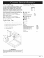
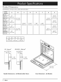
Installation
Discovery
EO, MOH
Pa_ No. 65433
Rev. L
WaJJ
and MOV
Series
Oven
Instructions
All specifications
are subject
to change without notice. Dacor ®assumes
© 2007 Dacor, all rights reserved.
no liability for changes
to specifications.
Before You Begin ..............................................................
Important Safety Instructions
..........................................
Important Information About Safety Instructions ..............
Safety Symbols and Labels .............................................
General Safety Precautions .............................................
Customer Service Information .........................................
If You Need Help ..............................................................
Product Data Plate ...........................................................
Model Identification ..........................................................
Product Specifications
.....................................................
Product Dimensions .........................................................
1
1
1
1
2
3
3
3
3
4
4
Planning the installation ...................................................
Selecting the Location ......................................................
Cabinet Cutout .................................................................
Electrical Specifications ...................................................
Installation instructions ....................................................
Parts List ..........................................................................
Electrical Service installation .........................................
Final Installation .............................................................
Verify Proper Operation .................................................
installation Checklist ......................................................
6
6
6
9
9
9
10
12
14
15
important:
•
Installer: In the interest of safety and to minimize problems, read these installation instructions completely and carefully before you begin the installation process. Leave these installation instructions with the customer.
•
Customer:
Keep these installation instructions for future reference and the local electrical inspector's use.
Important Information About
Safety Instructions
[_
IMPORTANT: Do not st0re or Use _stibJe;
flam:
mablel or explosiVe Vap0rS and liquids (such as gasoline)
The Important Safety Instructions
and warnings in
these instructions are not meant to cover all possible
problems and conditions that can occur. Use common
sense and caution when installing, maintaining or operating this or any other appliance.
•
ins!de o r in the Vicinity d this 0r any other appliance: AIS0
keep !tems that C0uld explode, such as aer0s01 cans i
away from the oven_ D0 n0t st0re flammabte or explos!ve
materials in adjacent cabinets or areas:
[_
Always contact the Dacor Customer Service Team
about problems and conditions that you don't understand. See Customer Service information.
[_
[_
DANGER
_
I lmmed! ate hazardS that WILL result in severe personal
l injury or death.
[_
]
I
J
WARNING
Hazards or UnSafe practices that COULD result in SeVere
personal injury or death.
CAUTION
Hazards or unSafe practices that COULD result in
perSonal injury Or property damagel
WARNING
1
WARNING _ NEVER use this appliance as a space
heater t0 heat Or Warm the room: DOing So may reSult in I
overheating of the appliancel
Safety Symbols and Labels
j
DANGER
WARNING _ NEVER COVeFany slOts, hOles Or passages
in the 0Yen bott0m 0r cover an entire rack With materials
Such as aluminum foil DOing SO blocks air floW through
the oven and may Cause a fire hazard Or carbon monoxide poisoning.
[_
1
WARNING
WARNING
instal ! this appliance
for example; near a pool:
1
oUtdOorS and/ornear water;
I
!_ WARNING
theBRm T ON
BROIL
set' I
tings, the oven d0or must be completely shuL
J
READ AND SAVE THESE INSTRUCTIONS
_a_D_
1
General Safety Precautions
To reduce the risk of fire, electric shock, serious injury or death when using your appliance, follow basic safety precautions, including the following:
WARNING
,
Read the accompanying use and care manUal
,
Keep PaCkaging mater als away from children,
Plastic sheets and bagS can Cause suffocationl
;
,
sure this applianCe iS Properly nStalled:
D0not use the do0r handle(s)t0 lift or move the
Oven
:i'
'
To prevent injury due to the unit tipping forward.
secure the oven to the cabinet using the supplied
mounting screws.
-
Keep flammable items, such as paper, cardboard.
plastic and cloth away from hot surfaces. Do not put
such items in the oven. Do not allow pot holders to
touch hot surfaces.
-
Do not wear loose or hanging apparel while using
the oven. Do not allow clothing to come into contact
with the interior of the oven and the surrounding
areas during and immediately after use.
-
Do not use the oven for storage.
-
Do not touch the interior surfaces of the oven during
use. After use, make sure these surfaces have had
sufficient time to cool before touching them.
-
Do not touch the outside surfaces of the oven during the self-clean cycle. They will be hot. Venting
from the oven may cause the trim to become hot.
-
For your safety, do not use the oven to cook without
the convection filter installed. When the filter is not
This oven must be properly installed and grounded
by a qualified installer according to these instal:
!ati0n inStrUctionsPri0r t0 Use: The installer must
A
"
-
you rece!ve a damaged prOdUcL immediately contact Your dealer or builderi Do not install or Use a
damaged appliance: DO not install or use the appli.
show the Customer the location of the cirCuit break:
: er panel or fus_! b0x SOthat they knowwhere and
h0w to turn off electric power t0 the
is not responsible for servic e required t0 correct a
faulty installationl The owner is resPonSible t0 make
,
WARNING
minimum 0f two people are required to safely
install this appliancel
To avoid an electriC shock hazard do not installthis
appliance OutSide or near Water:D0 not install or
use this appliance if it has been exp0sed t0 water:
DO not instal!;rePa!r or replace any part of the oven :
unless specifically recommended in the iterature
accompanying it: A qUalified seWice technician
should
perform all other service;
Bef0re performing any tYPe Of service or installai
tjon, make sure that the electdc power tothe oven
is turned off at the circuit breaker Or fuse box!
"
only use the oven for cook!ng tasks expected of a
home
appliance as out!jned in the literature accompanying it. This oven is not intended for commercial
use:
installed, the spinning fan blades at the back of the
oven are exposed.
Non-stick coatings, when heated, can be harmful to
birds. Remove birds to a separate, wel!-ventilated
room during cooking.
•
To prevent damage, remove the meat probe from
the oven when it is not being used.
-
Do not line the oven with aluminum foil or other
materials. These items can melt or burn up during
self-cleaning and cause permanent damage to the
oven.
-
Do not leave objects, such as aluminum foil, the
meat probe, cookie sheets, etc. on the bottom of
the oven. Objects left on the bottom of the oven
could damage the bake element. In addition, the
objects themselves could be damaged.
•
Do not allow heating elements in the top and bottom of the oven chamber to become covered up
by cookie sheets, aluminum foil, pots, pans, etc.
Covering the heating elements could cause them to
over-heat, damaging the oven.
•
Always ensure that the light fixture lens covers are
in place when using the oven. The lens covers protect the I_ght bulbs from breakage caused by high
......................................
Do not climb 0n any pait of the appliancel
Do not leave children alone or Unattended in the
area around the oven DO not allow childie n
with the controls; pul! on the handle or touch other
parts of the oven:
Do not store itemS of intereSt tO Children above the
OVenl Children could be burned or injured While
climbing on the appliance
;
;
DOnot tamper With the ContrOls: Do not adjust
Or
2
alter any part of the oven,
instructed to do so in this manual:
_8C0_
if You Need Help...
Model identification
If you have questions or problems with installation, contact
your Dacor dealer or the Dacor Customer Service Team.
For repairs to Dacor appliances under warranty call the
Dacor Distinctive Service line. Whenever you call, have the
model and serial number of the appliance ready. The model
and serial number are printed on the product data plate.
Dacor Distinctive
Service (repairs
under warranty
only)
Phone: (877) 337-3226 (U.S.A. and Canada)
Monday -- Friday 6:00 A.M.to 4:00 P.M.Pacific Time
Dacor Customer
Service
Phone: (800) 793-0093 (U.S.A. and Canada)
Monday -- Friday 6:00 A.M.to 5:00 P.M.Pacific Time
Web site: www.Dacor.com
Product Data Plate
The product data plate contains the model and serial
number information and the electrical requirements.
It is located inside the oven door, in the slot above the
left hinge (inside the lower door on a double oven). To
read the information on the data plate:
1.
Push the data plate tab.
2.
Pull the data plate up.
EO230×××
ttft
ABC
= MODEL TYPE
Epicure oven
Millennia oven (horiz. trim)
Millennia oven (vert. trim)
= EO
= MOH
= MOV
= CONFIGURATION
Single oven
Double oven
= 1
=2
= SIZE
27 inch = 27
30 inch = 30
= FINISH
Epicure:
Black glass
Stainless steel,
Stainless steel,
Stainless steel,
Stainless steel,
black chrome trim
chrome trim
brass trim
copper trim
=BK
= SBC
= SCH
= SBR
= SCP
Millennia:
Tab
Stainless steel
Data plate
@
Push the product
ing the dOorl
D
IMPORTANT
=S
Product Dimensions
All tolerances: +1/16 (+1.6 mm), unless otherwise stated.
Model
Number
A
B
C
D
E
F
G
H
EO127
25 3/8"
(64.4 cm)
27"
MOH127
(68.6 cm)
MOV127
27 15/16"
27 3/8"
EO130
(71.0 cm)
(69.5 cm)
28 3/8"
(72.1 cm)
30"
MOH130
(76.2 cm)
MOV130
EO227
23 3/8"
2 5/16"
7 3/8"
6 3/8"
(59.4 cm)
(5.9 cm)
(18.7 cm)
(16.2 cm)
25 3/8"
(64.4 cm)
27"
MOH227
(68.6 cm)
MOV227
EO230
51 1/16"
50 ½"
(129.7 cm)
(128.3 cm)
28 3/8"
(72.1 cm)
30"
MOH230
(76.2 cm)
MOV230
J
K
L
9/16"
(1.4 cm)
1"
(2.5 cm)
1 7/8"
(4.6 cm)
®
EO- Epicure
MOH/MOV
"-3
- Millennia ®
5/16"_
(8.4 cm)
f,2
I
22 11/16"
(57.6 cm)
Handle
4
_SCD_
Dimensions
-All
Models
(Side View)
Door Dimension
= All Models
Top of
chassis
H
1
(3.2 cm)
G
B
Control panel
front
66" (167.6 cm)
Flexible conduit
A
Chassis notch
side view
chassis
Single
Wall Oven
Dimensions
Top of
chassis
\
1 1/4"_
(3.2 cm)
Utility
cutout
Control panel
front
66" (167.6 cm)
Flexible conduit
A
Chassis notch
side view
of
chassis
Double
G
_-_
_,
Wall Oven
Dimensions
_a_D_
5
Selecting the Location
Model
Number
Carefully check the location where the oven is to be
installed. The oven should be placed for convenient
access, but away from drafts that may be caused by
doors, windows, and heating, ventilation and air conditioning outlets.
*
B
C
25 ½"
(64.8 cm)
(68.6 cm)
EO127
MOH127
Make certain that electrical power can be provided in
the selected location. Be certain that proper clearance
is provided for the oven door when it is in the open
position.
MOV127
27" 7/16"
EO130
(69.7 cm)
27"
28 ½"
MOH130
56 ½"
(143.5 cm)
62 ½"
30"
(72.4 cm)
(76.2 cm)
25 ½"
(64.8 cm)
(68.6 cm)
(158.8 cm)
MOV130
EO227
Cabinet Cutout
MOH227
Plan the installation so that all minimum clearances are
MOV227
met or exceeded. Cutout dimensions shown provide
minimum clearances, unless otherwise noted.
EO230
27"
50 9/16"
(128.4 cm)
NA
28 ½"
(72.4 cm)
MOH230
The specified minimum cabinet depth and width must
be provided. The cabinet depth and width must completely enclose the recessed portion of the oven.
*
A
30"
(76.2 cm)
MOV230
Cabinet cutout dimensions must be used as indicated.
Cutout tolerances: +1/16 (1.6 mm), -0, unless otherwise stated.
_
C
C
Recommended
electrical
location
Recommended
electrical
location
/
/
/
o
®
•
/
m
t
1" (2.5 cm)
min. clear to
bottom
of door
Single Wall
Oven Cutout
A
I
/
/
-"
_/4" (1.9 cm)
/
1" (2.5 cm) min.
Double Wall
Oven Cutout
clear to
bottom of
door
Alternate
electrical
location
A
/
/
support platform
//
4
I
a
t
1 3A"(4.5 cm) min.
clear to top of
door for heat
exhaust
®
1 3A"(4.5 cm) min.
clear to top of
31 1/4" (79.4 cm) door for heat
recommended
exhaust
(may be altered)
t
4" typical toe kick (shown)
A
/
/
/
u'
3/4" (1.9 cm)
support platform
.
4" typical toe kick (shown)
9 5/8" (24.4 cm)
recommended
(may be altered)
t
6
_SCD_
NOTES:
D
Recommended
electrical
location
Recommended
electrical
location
*
Cutout tolerances: +1/16 (1.6 ram), -0,
unless otherwise stated.
*
24" minimum cutout depth.
*
3/4" support platform must be flush with
front of cutout. See page 8.
\
•
•
i
•
•
i
t
1" (2.5 cm) min.
to bottom of
door
4"
(10.2 cm)
min._._._
between
cutouts
A
Duel Single Wall Oven
Cutout
A
- 3/4" (1.9 cm)
support platform
•
•
- 3/4" (1.9 cm)
support platform
i
1 ¾" (4.5 cm) min.
clear to top of
door for heat
exhaust
""
Alternate
electrical
location
Altern
electrical
location
31 1/4" (79.4 cm)
recommended
(may be altered)
4" typical toe kick (shown)
T
1" (2.5 cm) min. to combustibles
1 1/2''k
®
(3.8 cm)
typical counter
II
t
o
36" Typical
(91.4 cm)
A
1 ¾" (4.5 cm) min.
to combustible floor
I
I
_II
Recommended
electrical
location
3/4" (1.9 cm)
support platform
!.----I
®
Single Wall Oven
Under=Counter
Cutout
4" typical toe kick (shown)
Recommended
electrical location
/
1" (2.5 cm) min. to combustibles
(3.8 cm)
typical counter
J_
I
1 1/2''k
I
®
I
4" (10.2 cm) min._
between cutout
I
I
®
i
i
36" Typical
(91.4 cm)
A
A
a
1 ¾" (4.5 cm) mln.
to combustible floor
I II
_
I
3/4" (1.9 cm)
support platform
I_,
_,
i_
3/4" (1.9 cm)
upport platform
Alternate
electrical
locations
Duel Single Wall
Oven Under
Counter
Cutout
4" typical toe kick (shown)
_a_D_
7
Cabinet Cutout (Continued)
Support Platform
[_
WARNING
The t0p sUrface 0fthe support platform must be !nstalle_
flush with the cutout in the front of the cabinet or wall
and any trim Failure tO install the platform prOperly
may Cause the exhaUst vent to defo[m and/or become
obstructed: An obstructed exhaust area may cause the
oven to malfunction. See below.
Provide a platform within the cabinet to support the oven. A
properly supported piece of 3/4" (1.9 cm) thick plywood is
recommended.
All contact surfaces between the appliance and the cabinet, including the support platform, must be sturdy, straight
and level. The oven cannot be leveled after it has been
installed.
_=== Oven door
-_-====Cool air intake
z
,,"_
/J \
(do not block)
/,
Exhaust deflector
(do not bend)
Support platform
blockingDef°rmedventSheet
metali,__:_:._,
xha stven
(do not block)
//"/
Sheet metal on
bottom of oven
j
RIGHT
Support
8
L::_SCDtt,
Cabinet front or wall
Platform
Configuration
WRONG
JJ
Electrical Specifications
[_
-
iMPORTANT
Preheat times and cavity temperature recovery times
will be increased slightly if operating on less than a
240 Vac circuit.
• This appliance is provided with electrical connection
leads in a flexible metal conduit. These leads may be
a smaller gage than the standard household wiring of
the dedicated supply circuit, but they are suitable for
connection to these circuits under the jurisdiction of
the National Electric Code, and/or the local inspection
authority.
•
Locate the junction box so that the wiring may be disconnected without removing the oven from the wall.
It is the owner's responsibility to ensure that a qualified
electrician performs the electrical connection of this appliance. The electrical installation, including minimum supply
wire size, must comply with the National Electric Code
ANSI/NFPA 70 (latest revision) and local codes and ordinances.
A copy of this standard may be obtained from:
National Fire Protection Association
1 Batterymarch Park
Quincy, Massachusetts 02269-9101
The correct voltage, frequency and amperage must be supplied to the appliance from a dedicated, grounded, single
phase circuit that is protected by a properly sized circuit
breaker or time-delay fuse. If a time-delay fuse is utilized,
fuse both sides of the line (L1 and L2).
Dedicated
Model Type
Circuit
Total
Connected Load
Requirements
Single 27"
Single 30"
Double 27"
Double 30"
240 Vac 60 Hz.,
4 wire*, 30 Amp.
dedicated
4.6 kW (19.5 Amp.)
240 Vac 60 Hz.,
4 wire*, 50 Amp.
dedicated
9.25 kW (38.9 Amp.)
Two 120 Vac hot (LI and L2), one neutral, one ground.
The above electrical ratings are for reference only. For the
exact ratings see the product data plate. See page 3 for
location.
Parts List
Verify that all the parts are included. If any item is missing
or damaged, please contact your dealer immediately. Also
make certain that you have all tools and parts necessary to
ensure a proper installation before proceeding.
•
•
Exhaust deflector
¢
27" defector-
PN 46050B
or
¢
30" deflector-
•
PN 46051B
Mounting and exhaust deflector screw kit
0
Single oven screw kit - four (4) 3/4" mounting
screws, four (4) 1 1/4" mounting screws and three
(3) exhaust deflector screws - PN 700486-1
or
¢
Standard oven racks two (2) for a single oven, five (5)
for a double oven
0
27" standard rackor
PN 72747
0
30" standard rack-
PN 72713
GlideRack
TM
oven rack, one (1)
0
27" GlideRack
or
0
30" GlideRack
TM
oven rack-
PN 72948
TM
oven rack-
PN 72949
•
Stainless steel cleaner - stainless steel models only
PN A302
•
Product literature
Double oven screw kit - Six (6) 3/4" mounting
screws, six (6) 1 1/4" mounting screws and three
(3) exhaust deflector screws - PN 700486-2
•
Meat probe, one (1) - PN 72723
•
Broiler grill and pan - PN 12157
_a_D_
9
r-, ledr;ca
,,
I,
, , ,,
,,Insfallaf;on
WARNING
-
Wire the oven only in compliance with local ordinances.
• If the electrical service provided does not meet the
product specifications, do not proceed with the installation. Call a licensed electrician to install the required
wiring.
1
Before proceeding, turn off power to the circuit to which
the oven will be connected at the circuit breaker or fuse
box.
2.
Position the oven directly in front of the cabinet cutout.
3.
Feed the appliance conduit into the electrical junction
box and attach it using a UL approved strain relief.
4.
Depending upon local codes, utilize one of three methods to connect the appliance to the electrical power:
o To prevent an electric shock or fire hazard, turn off
power to the circuit at the circuit breaker or fuse box
prior to connecting the wiring to the oven.
-
Improper connection of the electrical wiring can cause
an electric shock hazard and damage the appliance.
Dacor is not responsible for damages resulting from
improper installation.
-
Connect the ground terminal (or lead) on the appliance
to a grounded, metallic, permanent wiring system or
grounding conductor.
•
Do not use an extension cord with this appliance.
Such use may result in fire, electric shock or other personal injury.
•
°
•
0
Connect to a four (4) wire electrical system
0
Connect to a three (3) wire electrical system, where
local codes permit
0
Connect to a three (3) wire electrical system with
external ground, according to local codes.
Connecting
to a Four (4) Wire Electrical
System
Do not install a fuse in the neutral or ground circuit. A
fuse in the neutral or ground circuit may result in an
electric shock hazard.
1.
Separate the wires coming out of the appliance conduit.
2.
Connect the white wire from the appliance conduit to
the white (neutral) supply wire in the junction box.
3.
Connect the black wire from the appliance conduit to
the black (L1) supply wire in the junction box.
4.
Connect the red wire from the appliance conduit to the
red (L2) supply wire in the junction box.
5.
Connect the green wire from the appliance conduit to
the green (ground) wire in the junction box.
The appliance must be connected to the power supply
with copper wire only. The use of aluminum wire may
result in unsatisfactory connections.
Cable from circuit breaker
]
Junction box
RED
RED
[_
IMPORTANT
Make sure that the conduit is long enough to allow the
even to be pulle d Out for serv!ce with0Ut disC0 nnecting it
from power.
panel or fuse box
|
Flexible armored or non-metallic, sheathed copper
cable (with grounding wire) should be used to connect
the appliance to the junction box. An UL-listed connector must be used to directly connect the cable to the
junction box.
1
GREEN
I
GREEN
WHITE
WHITE
BLACK
BLACK
II
\
\
Wire nut
(4 places)
Conduit to
wall oven
Four (4) Wire Junction
10 da=or
Box Connection
Connecting to a Three (3) Wire Electrical
System-Where
Local Codes Permit
[_
Connecting to a Three (3) Wire Electrical
System with External Ground - Where Local
Codes Permit
WARNING
[_
Do not connect the green appliance Conduit wire to the
unless Jocal building
codes permit.
J
1.
Separate the wires coming out of the appliance conduit.
2.
Connect the green and white wires from the appliance
conduit to the white (neutral) supply wire in the junction
box.
3.
Connect the black wire from the appliance conduit to
the black (L1) supply wire in the junction box.
4.
Connect the red wire from the appliance conduit to the
red (L2) supply wire in the junction box.
t
m
t
Cable
fromorcircuit
breaker
panel
fuse box
WARNING
-
Do not connect the green appliance wire to the junction box or to a cold water pipe unless local building
codes permit.
-
Do not ground the appliance to a gas supply p_pe or
hot water pipe.
•
If connecting the ground wire to a grounded cold water
pipe, connect using a separate copper grounding
wire (No. 10 minimum) and a clamp with an external
grounding screw. The grounded cold water pipe must
have metal continuity to electrical ground and must not
be interrupted by insulating materials. Any insulating
materials must be jumped, with a minimum, 4 AWG
wire to establish continuity to ground.
No. 4 copper
wire
Meter
Junction box
Metal water
pipe
GREEN
RED
RED
WHITE
Clamps
BLACK
Bare metal
BLACK
insulated
\
\
Wire nut
(3 places)
l_
Three
Conduit to
wall oven
(3) Wire Junction
Box Connection
(Where Local Codes Permit)
=
[_
Pipe Jumper
NOTE
If the junction boX has been properly gi0unded by a
licensed electrician, the green (ground)wire from the
appliance condu!t may be COnnected t0the junction bOX
using a loop terminal
See the diagram on the following page. To connect the
green appliance conduit wire to a grounded cold water
pipe:
1. Separate the wires coming out of the appliance conduit.
2. Connect the white wire from the appliance conduit to the
white (neutral) supply wire in the junction box.
3. Connect the black wire from the appliance conduit to the
black (LI) supply wire in the junction box.
4. Connect the red wire from the appliance conduit to the
red (L2) supply wire in the junction box.
5. Connect the green wire from the appliance conduit to a
grounded cold water pipe as shown. Jumper any insulating
materials as shown above with a length of No. 4 copper
wire. Securely clamp the wire to bare metal at both ends.
dacD_
11
Connecting to a Three (3) Wire Electrical
System with External Ground - Where Local
Codes Permit (Continued)
Cable from circuit
Separate No. 10 min.
copper grounding wire
breaker panel or
fuse box
Junction box
(4 places)
/
WHITE
WHITE E_/
BLACK
BLACK _
L
i
onduit
to
wall
oven
Three
(3) Wire Connection
Final Installation
WARNING
-
A minimum of two people are required to safely install
this appliance.
-
Do not attempt to disengage the hinge catches with
the door removed from the oven. The hinge springs
could release, causing personal injury.
-
Do not lift or carry oven door by the door handle.
•
On double ovens, remove the bottom door first to
reduce the chance of damage.
Removing the Oven Door(s)
Due to the weight of this appliance, remove the door(s) to
reduce the lifting load. Removing the door(s) will also provide a place to grip the oven when lifting it into place.
1.
Open the oven door completely.
2.
Pull the hinge locks forward on both hinges, until they
stop.
12 dater
with
External
Ground
3. Raisethedoorso thatit is ata 15° anglefromthefront
of theoven.Holdthedoorwithonehandoneachside.
Liftthedoorupandout.
,
,
Support the oven at all times until it is secured into the
cabinet. Be certain to take all necessary safety precautions.
Resting the oven on the cabinet support platform, slide
the oven into the recessed area until the rear edge of
the oven trim post is flush with the cabinet face and
the oven is centered within the cutout. Ensure that
the electrical conduit slides through the opening in the
cabinet platform or coils above the oven chassis as the
oven is slid into place. Do not trap the appliance cable
between the oven case back and the rear wall.
i i
,
Door Gripping
Points
Make sure the oven is resting level. Shim it if necessary.
[_
When installing the mounting screws into composite
cabinets; install them into the sides of the cabinet only;
Maunt!ng ScreWS installed into the front Of composite
cabinets will have a tendency to pull loose:
Install the Oven in the Cabinet
[_
WARNING
WARNING
•
Use an appliance dolly to move the appliance when
installing it or removing it from the wall for service. Use
of an appliance dolly will minimize the risk of personal
injury as a result of the oven tipping.
•
Failure to install the mounting screws may result in
movement or tipping of the oven during use, or personal injury.
5. Find the mounting hole locations in the front and side
of the oven trim posts. Drill 1/16" pilot holes in the cabinet
through the front or side of the trim posts. Single oven
models require four (4) holes, while double oven models
require six (6).
6. Install the #6 x 3/4" screws provided in the instructions
envelope. Do not over-tighten.
Do not block the oven air exhaust and intake located
at the bottom of the oven door(s). Blocking the airflow
may cause cabinet damage and poor baking performance.
DDODOD
©
IMPORTANT
An Oven that is n0t !evel may Provide POOrOr inconsistent
baking results:
1.
_
J
Lift the oven up to the cabinet cutout using the handles
and gripping points shown. Use extreme caution when
lifting the appliance, because it is heavy.
jz
\
Trim post
©
©
Handle
Gripping points
Trim post
I_
o 11
4_
Gripping point
dacDr,
13
Install Exhaust Deflector
L
CAUTION
1.
i
,
I Instal the exhaust deflect0r before i!Staling the 0 ven
l d°°r(s)
,
1
Attach the exhaust deflector to the front of the oven. It
attaches to the oven just below the oven chamber in the
door jam. On a double oven, the exhaust deflector is
mounted below the bottom oven chamber.
1.
Line up the mounting holes on the exhaust deflector
with the screw holes on the front of the oven.
2.
Secure it using the three (3) screws provided.
,
5.
Grasp the oven door on opposite sides and hold it at a
15 ° angle from the front of the oven. See facing page.
Slide the hinges into the hinge openings, resting the
bottom of the hinge arms on the hinge receptacles.
Continue to hold the door at a 15° angle with one hand
while pushing in on each of the bottom corners of the
door. Push until the notch on the bottom of each hinge
slips over the lower lip of each hinge receptacle.
Lower the door to the fully opened position.
Rotate the two hinge locks toward the oven. Slowly and
carefully open and close the door completely to make
sure that it is properly installed.
Verify Proper Operation
i
!_
WARNING
I Read the accompanying use and care manual completely I
before using the OVenl
1
1.
Remove any packaging from inside the oven(s).
2.
On some models there is protective plastic coating over
the stainless steel surfaces. Peel them off before use.
3.
Slide the oven racks onto the support racks in the oven
chamber(s) as instructed in the use and care manual.
4.
Turn on the power to the oven at the circuit breaker
or fuse box. Set the clock as instructed in the use and
care manual.
5.
Set the oven to bake mode as instructed in the use and
care manual.
NOTES: If the oven does not operate properly, follow these
troubleshooting steps:
Reinstall the Oven Door(s}
[_
WARNING
To avoid damage to the door or personal injury from it
falling off its hinges:
-
-
Make sure that the notch on the bottom of each hinge
rests on top of the lower lip of each hinge receptacle
before attempting to open the oven door.
CAUTION
ond 0uble ovens: Install e Upper do0r firs t t0 prevent
damage to the lower door:
14 da=ar
Verify that power is supplied to the oven.
•
Check for proper electrical connection.
•
Repeat the above bake test.
•
If the appliance still does not work, contact Dacor
•
Distinctive Service at (877) 337-3226. Do not attempt
to repair the appliance yourself. If you need service, be
sure to have the model and serial numbers available
when you call. See page 3 for location.
Dacor is not responsible for the cost of correcting problems
caused by a faulty installation.
Rotate the hinge locks toward the front of the oven
immediately and completely after installation of the
door.
[_
•
1
I
1
Lowerlipof
hingereceptacle
Notchon bottom
of hinge
Door
Installation
Installation Checklist
WARNING
To ensure a safe and proper installation, the following checklist should be completed by the installer to
ensure that no part of the installation has been overlooked.
Proper installation is the responsibility of the homeowner. The importance of proper installation of your
Dacor oven cannot be overemphasized,
[]
Oven is wired to all applicable codes and Dacor specifications. See pages 9 and 10.
[]
Oven is level. See page 13.
[]
Oven is secured into cabinet with included screws. See
[]
Plastic coating, if applicable, has been removed from
outside of oven,
[]
All packaging materials have been removed from inside
the oven.
[]
Power is turned on at circuit breaker or fuse box.
[]
Proper oven operation has been verified. See page
14.
[]
Problems have been noted on the warranty card or during the on-line activation. Warranty has been activated
on-line or the warranty card has been filled out completely and mailed.
page 13.
[]
Exhaust deflector has been installed. See page 14.
[]
Oven door(s) have been properly re-installed. See
page 14.
dacDr,
15
16 da=_r
The Life of the Kitchen?
Dacor = 600 Anton Blvd. Suite 1000 Costa Mesa, CA 92626 = Phone: (800) 793-0093 = Fax: (626)403-3130
Family Owned
American Made
= www.Dacor.com