1
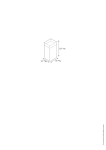
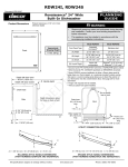
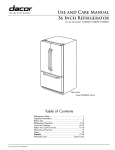
INSTALLATION INSTRUCTIONS
For DACOR Built-in Kit Model AOCTK27 or AOCTK30
THIS KIT IS UL APPROVED TO ALLOW CERTAIN MICROWAVE OVENS TO BE INSTALLED ABOVE CERTAIN CONVENTIONAL/CONVECTION WALL OVENS.
PLEASE SEE THE OPERATION MANUAL REGARDING BUILT-IN APPLICATIONS.
IF YOUR LOWER CONVENTIONAL OVEN IS NOT LISTED IN THE OPERATION MANUAL OR THE INSTALLATION INSTRUCTIONS OF THE MICROWAVE OVEN
AS AN APPROVED MAKE AND MODEL, THEN DO NOT INSTALL THE MICROWAVE OVEN IN ANY AREA WHERE HEAT AND STEAM ARE GENERATED; FOR
EXAMPLE, NEXT TO OR ABOVE A CONVENTIONAL RANGE OR ABOVE A CONVENTIONAL WALL OVEN.
Microwave Oven: DCM24
Lower Oven: EO127, EO130, MOV127, MOH127, MOV130, MOH130, PO127, PO130
Do not build-in above any other gas or electric wall oven.
PLEASE READ THESE INSTRUCTIONS THOROUGHLY BEFORE BEGINNING INSTALLATION!
• Be sure to DISCONNECT THE PLUG of the microwave oven from the electrical outlet before installing the Built-in Kit.
Remove the turntable from the oven cavity.
• Because the kit includes metal parts, due caution should be used in handling and installation to avoid the possibility of
injury.
• Do not remove permanently affixed labels, warnings or plates from the product. This may void the warranty.
• Please observe all local and national codes and ordinances.
• The installer should leave these instructions with the consumer who should retain for local inspector’s use and
for future reference.
PARTS INCLUDED IN THE KIT
6 DUCT-A1: QTY 1
1 FRONT FRAME
ASSEMBLY: QTY 1
7 DUCT-A2: QTY 1
2�BOTTOM DUCT:
QTY 1
8 DUCT-A3: QTY 1
9 DUCT-B: QTY 1
3�SCREW-A (1/2"
LENGTH): QTY 10
4�SCREW-B (1 3 /4"
LENGTH): QTY 4
! DUCT-C: QTY 1
5�SCREW-C (1 3 /16"
LENGTH): QTY 2
CORD BOX: QTY 1
1
STEP 1
CABINET OR WALL OPENING
Figure 1
CABINET OR WALL OPENING
Provide an opening in the wall or cabinet as indicated on
figure 1. The depth should be a minimum of 24". The floor
of the opening should be constructed of plywood strong
enough to support the weight of the oven (about 100 lbs.)
and should be level for proper operation of the oven.
5"
Note: While the proper functioning of the oven does not
require that the opening be enclosed (with sides, ceiling and
rear partition), this may be required by local code, and it
is suggested that the local code be checked for any such
requirement.
18 1/ 2 "
11 1/ 2 "
20 1/ 8 "
ELECTRICAL OUTLET LOCATION
This outlet should not be located in the shaded area of figure
1. At the rear of the opening, provide a 3-pronged, polarized,
electrical outlet, 115-120 volt A.C., 15 amp. or larger.
STEP 2
25 1/ 4 "
EXHAUST DUCT ASSEMBLY INSTALLATION
1. Insert the edge of DUCT-B into the hold lip of DUCT-C.
Secure together by using a SCREW-A provided in the kit.
Remove the existing screw #1 at upper right rear of the
oven and secure DUCT-C with the screw #1 just removed
from the oven. Secure DUCT-B with SCREW-A through
the duct and into the original screw hole in the oven. See
figure 2.
3. Position DUCT-A2 on top of the oven and insert it into the
hold lip of DUCT-A1. Secure DUCT-A2 to DUCT-A1 using
two SCREWS-A provided. See figure 4.
4. Position DUCT-A3 on top of the oven and insert it into
DUCT-A2. Secure DUCT-A3 using three SCREWS-A
provided.
2. Secure the EXHAUST DUCT ASSEMBLY with two
SCREWS A. See Figure 3.
Figure 3
Figure 2
DUCT-A1
SCREW-A
DUCT-C
DUCT-B
DUCT-B
SCREW-A
SCREW-A
SCREW-A
#1
2
Figure 4
Figure 5
SCREW-A
DUCT-A3
DUCT-A2
SCREW-A
SCREW-A
DUCT-A1
STEP 3
SCREW-A
DUCT-A2
CORD BOX
1. Plug the oven electrical cord into the CORD BOX
RECEPTACLE and roll the remaining part of the cord into
the CORD BOX as shown in Figure 6-A.
Figure 6
6-A
CUSHION-A
2. Remove screw #2 from lower left rear of the oven. Insert
right flange of the CORD BOX into hold lip of the oven.
Using the screw #2 just removed from the oven, secure
the CORD BOX to the oven. See Figure 6.
CORD BOX
#2
STEP 4
SCREW-A
INSTALLATION
Figure 7
1. Place oven on bottom duct and slide assembly partially
into cutout, leaving room to reach in and connect the cord
to the electrical outlet.
2. Slide the oven into place. Be sure the oven is placed at
the center of the opening.
SCREWS
BOTTOM
PLATE
CUSHION-B
3
STEP 5
FRAME INSTALLATION
Figure 8
Attach bottom duct with two SCREWS-C. Attach built-in
trim kit frame with four SCREWS-B. See figure 8.
SCREW-B
SCREW-C
SCREW-B
SCREW-B
SCREW-C
SCREW-B
OVER OVEN INSTALLATION
OVER WARMING OVEN INSTALLATION
TOP OF
MICROWAVE
SHELF
MICROWAVE
CUTOUT
1 3 /4 "
MICROWAVE
CUTOUT
EPICURE,
PREFERENCE AND
MILLENNIA
SINGLE WALL
OVEN CUTOUT
41"
DACOR INC.
1440 Bridge Gate Drive • Diamond Bar, CA 91765
1-800-793-0093 • www.dacor.com
4
1 1/4 "
WARMING
OVEN CUTOUT
(ALL MODELS)
RECOMMENDED
HEIGHT 36"
TINSEB423MRR0