1
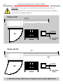
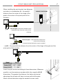
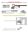
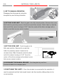
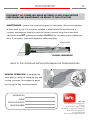
Phobos N BT installation manual version 120626 Phobos N L BT tuned to you Professional installation required 2 APPLICATIONS & CAPACITIES Important. This product is intended to be installed and serviced by a professional technician. The product warranty may be voided if installed or serviced by a unqualified person. Phobos N BT 32-1/2” OUTSIDE 90° 550 lbs 10 feet 2” max hinge offset* Phobos NL BT 37” OUTSIDE 110° 550 lbs 16 feet * 3” max hinge offset* Maximum hinge offset does not apply to push to open applications 3 TABLE OF CONTENTS APPLICATIONS AND CAPABILITIES 2 PHOBOS N BT PHOBOS NL BT INSTALLATION SAFETY 4 GATE AUTOMATION INSTALLATION SAFETY UL 325 VEHICULAR GATE CLASSIFICATION UL 325 ENTRAPMENT PROTECTION REQUIREMENTS UL 325 INSTALLATION RECOMENDATIONS OPERATIONAL SAFETY 5 GENERAL SAFETY CHECKING INSTALLATION ADJUSTING OPERATING FORCE CONTROL OPERATIONAL SAFETY THE INSTALLER'S CHECKLIST 6 POST BRACKET MOUNTING 7 GATE BRACKET MOUNTING 8 MOUNTING THE ACTUATOR 9 SETTING THE LIMITS 10 MANTAINENCE 11 TECH SUPPORT U.S. TOLL FREE: 877-995-8155 / INT'L: +1-561-995-8155 4 INSTALLATION SAFETY GATE AUTOMATION INSTALLATION SAFETY While the manufacturer has designed the system under strict safety standards, it is ultimately the installers responsibility to follow and comply with national and local laws, codes and safety standards that apply to the mechanical, electrical and operational aspects of the gate automation system. These include but are not limited to: safety standards established by entities like Underwriters Laboratory (UL), NFPA 70, or codes and laws stated by corresponding state, county or municipality. While it may not be compulsory, we highly recommend following UL 325 safety standards. UL 325 VEHICULAR GATE AUTOMATION CLASSIFICATION This system can be used in Class I, Class II and Class III applications. ● ● ● ● CLASS I – RESIDENTIAL VEHICULAR GATE OPERATOR - A vehicular gate operator (or system) intended for use in a home of one-to four single family dwelling, or a garage or parking area associated therewith. CLASS II – COMMERCIAL/GENERAL ACCESS VEHICULAR GATE OPERATOR - A vehicular gate operator (or system) intended for use in a commercial location or building such as a multi-family housing unit (five or more single family units), hotel, garages, retail store, or other building servicing the general public. CLASS III – INDUSTRIAL/LIMITED ACCESS VEHICULAR GATE OPERATOR - A vehicular gate operator (or system) intended for use in an industrial location or building such as a factory or loading dock area or other locations not intended to service the general public. CLASS IV – RESTRICTED ACCESS VEHICULAR GATE OPERATOR - A vehicular gate operator (or system) intended for use in a guarded industrial location or building such as an airport security area or other restricted access locations not servicing the general public, in which unauthorized access is prevented via supervision by security personnel. UL 325 ENTRAPMENT PROTECTION REQUIREMENTS For all installation classes, it is required to properly adjust the inherent obstruction sensing system and install warning signs on both sides of the gate, warning pedestrians of the dangers of the automated gate system. For Class I and Class II installations, it is required to add a non-contact device, such as a photoelectric eye OR a contact device such as a gate edge. For Class III installations it is required to add a non-contact device, such as a photoelectric eye, AND a contact device such as a gate edge OR an audio alarm such as a siren, horn or buzzer. UL325 INSTALLATION RECOMMENDATIONS 1. Install the gate operator only when: a. The operator is appropriate for the construction and the usage class of the gate. b. All openings of a horizontal slide gate are guarded or screened from the bottom of the gate to a minimum of 4' (1.2 m) above the ground to prevent a 2-1/4" (6 cm) diameter sphere from passing through the openings anywhere in the gate, and in that portion of the adjacent fence that the gate covers in the open position. c. All exposed pinch points are eliminated or guarded, and guarding is supplied for exposed rollers. 2. The operator is intended for installation only on gates used for vehicles. Pedestrians must be supplied with a separate access opening. The pedestrian access opening shall be designed to promote pedestrian usage. Locate the gate such that persons will not come in contact with the vehicular gate during the entire path of travel of the vehicular gate. 3. The gate must be installed in a location so that enough clearance is supplied between the gate and adjacent structures when opening and closing to reduce the risk of entrapment. Swinging gates shall not open into public access areas. 4. The gate must be properly installed and work freely in both directions prior to the installation of the gate operator. 5. Controls intended for user activation must be located at least six feet (6') away from any moving part of the gate and where the user is prevented from reaching over, under, around or through the gate to operate the controls. Outdoor or easily accessible controls shall have a security feature to prevent unauthorized use. 6. The Stop and/or Reset (if provided separately) must be located in the line-of-sight of the gate. Activation of the reset control shall not cause the operator to start. 7. A minimum of two (2) WARNING SIGNS (supplied with the gate operator) shall be installed, one on each side of the gate where easily visible. 8. For a gate operator utilizing a non-contact sensor: a. Reference owner’s manual regarding placement of non-contact sensor for each type of application. b. Care shall be exercised to reduce the risk of nuisance tripping, such as when a vehicle trips the sensor while the gate is still moving. c. One or more non-contact sensors shall be located where the risk of entrapment or obstruction exists, such as the perimeter reachable by a moving gate or barrier. 9. For a gate operator utilizing a contact sensor such as an edge sensor: a. One or more contact sensors shall be located where the risk of entrapment or obstruction exists, such as at the leading edge, trailing edge and post mounted both inside and outside of a vehicular horizontal slide gate. b. One or more contact sensors shall be located at the bottom edge of a vehicular vertical lift gate. c. A hard wired contact sensor shall be located and its wiring arranged so the communication between the sensor and the gate operator is not subject to mechanical damage. d. A wireless contact sensor such as the one that transmits radio frequency (RF) signals to the gate operator for entrapment protection functions shall be located where the transmission of the signals are not obstructed or impeded by building structures, natural landscaping or similar obstruction. A wireless contact sensor shall function under the intended end-use conditions. e. One or more contact sensors shall be located on the inside and outside leading edge of a swing gate. Additionally, if the bottom edge of a swing gate is greater than 6" (152 mm) above the ground at any point in its arc of travel, one or more contact sensors shall be located on the bottom edge. f. One or more contact sensors shall be located at the bottom edge of a vertical barrier (arm). OPERATIONAL SAFETY 5 GENERAL SAFETY WARNING! An incorrect installation or improper use of the product can cause damage to persons, animals or property. • Automation should be installed on a gate which is moving freely. Any issue with the smooth opening of closing of a gate will not be corrected by adding automation. • Scrap packing materials (plastic, cardboard, polystyrene etc) according to the provisions set out by current standards. Keep nylon or polystyrene bags out of children’s reach. • Keep this instruction manual for future reference. • This product was exclusively designed and manufactured for the use specified in the present documentation. Any other use not specified in this documentation could damage the product and be dangerous. • The Company declines all responsibility for any consequences resulting from improper use of the product, or use which is different from that expected and specified in the present documentation. • Do not install the product in explosive atmosphere. • The Company declines all responsibility for any consequences resulting from failure to observe Good Technical Practice when constructing closing structures (door, gates etc.), as well as from any deformation which might occur during use. • Follow and comply with national and/or local electrical codes when performing any electrical installation. • Disconnect the electrical power supply before carrying out any work on the installation. Also disconnect any buffer batteries, if fitted. • Fit all the safety devices (photocells, electric edges etc.) which are needed to protect the area from any danger caused by squashing, conveying and shearing, according to and in compliance with the applicable directives and technical standards. • It is recommended to position at least one luminous signal indication device (blinker) where it can be easily seen for additional safety • The Company declines all responsibility with respect to the automation safety and correct operation when other manufacturer ’s components are used. • Only use original parts for any maintenance or repair operation. • Do not modify the automation components, unless explicitly authorized In writing by the Company. • Instruct the product user about the control systems provided and the manual opening operation in case of emergency. • Anything which is not expressly provided for in the present instructions, is not allowed. • Installation must be carried out using the safety devices and controls prescribed by the UL 325 Standard. CHECKING INSTALLATION Before the automated device is finally put into operation, perform the following checks meticulously: • Make sure all components are fastened securely. • Check that all safety devices (photocells, pneumatic safety edge, etc.) are working properly. • Check the emergency operation control device. • Check opening and closing operations with the control devices applied. • Check the electronic logic for normal (or personalized) operation in the control panel. ADJUSTING OPERATING FORCE WARNING: Operating force is adjusted with extreme precision by means of the control unit’s electronic control. Operation at the end of travel is adjusted electronically in the control panel. To provide good anti-crush safety, the operating force must be slightly greater than that required to move the leaf both to close and to open it. CONTROL There are various options when it comes to the control system (manual, remote control, access control with magnetic badge, etc.) depending on the installation’s needs and characteristics. See the relevant instructions for the various control system options. People due to use the automated device must be instructed how to control and use it. OPERATIONAL SAFETY The installer is responsible for communicating the following information to the end-user: This product has been designed and built solely for the purpose indicated herein. Uses not contemplated herein might result in the product being damaged and could be a source of danger. The Firm disclaims all responsibility resulting from improper use or any use other than that for which the product has been designed, as indicated herein, as well as for failure to apply Good Practice in the construction of entry systems (doors, gates, etc.) and for deformation that could occur during use. If installed and used correctly, the automated system will meet the required level of safety. Nonetheless, it is advisable to observe certain rules of behavior so that accidental problems can be avoided: ● Keep adults, children and property out of range of the automated system, especially while it is operating. ● Operate the system when the full path of the gate is within sight. ● It is essential to frequently check that all safety devices are in good working condition. ● This application is not meant for use by people (including children) with impaired mental, physical or sensory capacities, or people who do not have suitable knowledge, unless they are supervised or have been instructed by people who are responsible for their safety. ● Children must be supervised to ensure they do not play with the system. Keep remote controls or other control devices out of reach of children in order to avoid the automated system being operated inadvertently. ● Check the system frequently, especially hinges, cables, springs or supports, to detect any loss of balance and signs of wear or damage. ● When cleaning the outside or performing other maintenance work, always cut off mains power. ● Keep the photocells’ optics and illuminating indicator devices clean. Check that no branches or shrubs interfere with the safety devices (photocells). ● Do not use the automated system if it is in need of repair. In the event of a malfunction, cut off the power, activate the emergency release to allow access and call in qualified technical personnel (professional installer). ● If the automated system requires work of any kind, employ the services of qualified personnel (professional installer). ● Anything that is not explicitly provided for in these instructions is not allowed. ● The operator’s proper operation can only be guaranteed if the information given herein is complied with. The Firm shall not be answerable for damage caused by failure to comply with the installation rules and instructions featured herein. ● Have the complete system checked including all safety devices by a qualified professional technician at least once a year. Descriptions and illustrations herein are not binding. While we will not alter the product ’s essential features, the Firm reserves the right, at any time, to make those changes deemed necessary to improve the product from a technical, design or commercial point of view, and will not be required to update this publication accordingly. 6 THE INSTALLER'S CHECKLIST Installing the actuator in the order described below will ensure proper and faster installation. CAREFULLY READ ALL SAFETY INFORMATION. PAGES 4 & 5 INSTALL THE POST BRACKET. PAGE 7 INSTALL THE GATE BRACKET. PAGE 8. INSTALL THE MAGNET HOLDER. PAGE 8 WIRE THE MOTORS. PAGE 9. ATTACH THE ACTUATORS TO THE MOUNTING BRACKETS. PAGE 9. SET THE LIMIT SWITCHES. PAGE 1 0. PROCEED TO INSTALL THE CONTROLLER. FINE-TUNE THE LIMITS SENSORS. INSTALL THE SNAP-RINGS. TECH SUPPORT U.S. TOLL FREE: 877-995-8155 / INT'L: +1-561-995-8155 7 POST BRACKET MOUNTING When installing the post bracket, two distances are taken in consideration: A – the parallel PHOBOS' PIVOT POINT distance from the center of the hinge of the gate to the center of the pivot point of the actuator... PIVOT POINT A PIVOT POINT — — — — — — — — — — — — — — — — — — — — — — — A Pull-to-open (standard installation) A is measured away from the center of the driveway Push-to-open - A is measured towards the ─ ─ ─ ─ ─ ─ ─ ─ ─ ─ ─ ─ ─ ─ A center of the driveway *Custom bracket fabrication may be needed A 0.28" ...and B – the perpendicular distance from the center of the hinge of the gate and the — — — — — — — — — — — — — — — — — — — — — — — B pivot point of the actuator B Model A&B Phobos N BT 5.25” ~ 5.75” Phobos N L BT 7” ~ 7.5” Install the post bracket according to these dimensions. Whenever possible, use the maximum number within the range for A & B dimensions. The greater the distance, the better mechanical advantage the actuator will have to move and hold the gate. Metal custom fabrication might be needed in some cases. 8 GATE BRACKET MOUNTING C Phobos N BT 27.5” Phobos N L BT 32” C — — — — — — — — — — — — — — — — — — — — — — — Model C When measuring C dimension, the gate must be at its fully closed position. The measurement for the C dimension is taken from the center of the actuator's pivot point, to the center of the attach point of the gate bracket. Center of attach point For push-to-open installations, C must be measured with the gate open at 90° Weld or bolt the gate bracket to the gate If welded, wait for the bracket to cool down. Install the magnet holder over the gate bracket. MOUNTING THE ACTUATOR 9 1) WIRE THE MOTORS - Before attaching the actuator to the mounting brackets, wire the motor cable (included) and then install the protective cover as illustrated. The supplied rubber grommet for the cable must be installed to keep moisture out of the motor limit board.. Rubber grommet 16 AWG STRANDED OR BETTER WHITE RED BLACK 2) ATTACH THE ACTUATOR - Follow illustrations to install the actuator to the post and gate brackets. TIP: Do not install the snap rings yet. Making adjustments during installation is much easier when the actuators can be slid off its brackets. Do not lose the snap rings! 10 SETTING THE LIMITS 1) SET TO MANUAL OPERATION Disengage the drive gear by using the triangular key and turning clockwise. 2) SET THE CLOSE LIMIT - Push the gate to its fully closed position. Remove the screw that holds the proximity sensor at the front end of the actuator. Slide it back so that the back end of the sensor housing is 3-1/2” from the center of the drive carriage and reattach screw that secures sensor in place. 3) SET THE OPEN LIMIT - Push the gate to its fully open position. Remove the screw that holds the proximity sensor closest to the actuator body. Slide it forward so that the back end of the sensor housing is 3-1/2” from the center of the drive carriage and re-attach screw 3-1/2” that secures sensor in place. 4) RE-ENGAGE THE MANUAL RELEASE - Use triangular key and turn counterclockwise to re-engage gears. 5) FINE-TUNING THE LIMITS – Once the actuator is connected to the controller, it must be powered and the limits might have to be fine-tuned by slidong them to the correct position. 11 MANTAINENCE DISCONNECT ALL POWER INCLUDING BATTERIES IF APPLICABLE BEFORE PERFORMING ANY MAINTENANCE OR REPAIR TO THE ACTUATORS MAINTENANCE - Inspect the screw-drive gears for lubrication, debris and cleanness at least once a year. For actuators installed in areas where dirt and dust are a concern, maintenance should be done at shorter intervals. Keep the screw-drive lubricated using BFT grease part number: I101115. Do not apply grease if gears are dirty. If necessary, clean with degreaser before applying. SCREW-DRIVE PHOBOS UNDERSIDE REFER TO THE CONTROLLER INSTALLATION MANUAL FOR TROUBLESHOOTING MANUAL OPERATION - Disengage the drive gear by using the triangular key and turning clockwise. Re-engage the gears by turning the key counterclockwise. INSTALLED BY: PHONE: INSTALLATION DATE: INVOICE NUMBER: BFT USA 6100 Broken Sound Pkwy N.W. Suite 14 Boca Raton FL 33487, U.S.A. Toll Free (U.S. Only): 877-995-8155 Main Office: 561-995-8155 Fax: 561-995-8160 Email: [email protected] 30 Months Limited Warranty BFT protects its customers with an exclusive warranty valid for 3 0 months from the date of manufacture of the product. The return of a product covered by the terms of the warranty will result in its replacement with a newly manufactured equivalent product. The calculation of the 3 0 months ’ warranty runs from the date of manufacture, shown on the product in the form of an impressed code or an applied adhesive label. Counter feiting or deleting the date of manufacture voids the validity of the warranty. To benefit from this special formula, the customer must accompany the returned goods with a transport document on which the following must obligatorily be indicated: - The product code; - The detailed description of the product; - The quantity returned. The warranty cannot be applied if: ● The equipment has been installed or serviced by a person other than a qualified professional technician; • The failure has been caused by a system not installed in accordance with the instructions supplied by the company; • Components which are not original BFT parts have been used for installing the motorization; • The failures are the result of tampering or improper repairs; • The failures have been caused by improper or careless use; • The causes of the failure are due to external agents such as: electrical discharges, tampering even accidental, impact even by accident, exposure to moisture or steam, use in extreme environmental or heat conditions, floods or other natural calamities. The replacement of parts during the warranty period shall not give rise to an extension of the expiry date of the warranty itself. No compensation shall be payable for the period during which the faulty system is inactive. BFT shall not be responsible for any damages, direct or indirect, caused to persons, things or pets by failure of the product, use for purposes not appropriate to its nature and/or its capacity, use over its capacity limit, and forced suspension in its use. The rights expressly envisaged in the consumer ’s favor by the regulations governing the sale of consumer goods are not affected in any way by this warranty. BFT U.S. Inc 61 00 Broken Sound Pkwy N.W., Suite 14, Boca Raton, FL 33487 U.S. Toll Free: 877-99 5-8155; Office: 561-99 5-8155; Fax: 561-99 5-81 60 Website: www.bft-usa.com Email: [email protected]