1
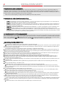
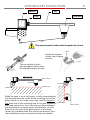
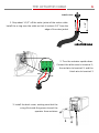
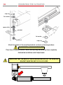
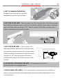
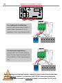
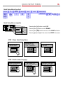
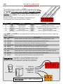
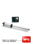
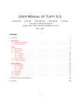
Phobos N L BT
installation manual
version 130308
Thalia control board
tuned to you
Professional installation required
welding might be needed
2
INSTALLATION SAFETY
GATE AUTOMATION INSTALLATION SAFETY
While the manufacturer has designed the system under strict safety standards, it is ultimately the installers responsibility to follow and
comply with national and local laws, codes and safety standards that apply to the mechanical, electrical and operational aspects of the gate
automation system. These include but are not limited to: safety standards established by entities like Underwriters Laboratory (UL), NFPA 70,
or codes and laws stated by corresponding state, county or municipality.
While it may not be compulsory, we highly recommend following UL 325 safety standards.
UL 325 VEHICULAR GATE AUTOMATION CLASSIFICATION
This system can be used in Class I, Class II and Class III applications.
●
●
●
●
CLASS I – RESIDENTIAL VEHICULAR GATE OPERATOR - A vehicular gate operator (or system) intended for use in a home of one-to
four single family dwelling, or a garage or parking area associated therewith.
CLASS II – COMMERCIAL/GENERAL ACCESS VEHICULAR GATE OPERATOR - A vehicular gate operator (or system) intended for use
in a commercial location or building such as a multi-family housing unit (five or more single family units), hotel, garages, retail store, or
other building servicing the general public.
CLASS III – INDUSTRIAL/LIMITED ACCESS VEHICULAR GATE OPERATOR - A vehicular gate operator (or system) intended for use in
an industrial location or building such as a factory or loading dock area or other locations not intended to service the general public.
CLASS IV – RESTRICTED ACCESS VEHICULAR GATE OPERATOR - A vehicular gate operator (or system) intended for use in a guarded
industrial location or building such as an airport security area or other restricted access locations not servicing the general public, in which
unauthorized access is prevented via supervision by security personnel.
UL 325 ENTRAPMENT PROTECTION REQUIREMENTS
For all installation classes, it is required to properly adjust the inherent obstruction sensing system and install warning signs on both sides of the
gate, warning pedestrians of the dangers of the automated gate system. For Class I and Class II installations, it is required to add a non-contact
device, such as a photoelectric eye OR a contact device such as a gate edge. For Class III installations it is required to add a non-contact device,
such as a photoelectric eye, AND a contact device such as a gate edge OR an audio alarm such as a siren, horn or buzzer.
UL325 INSTALLATION RECOMMENDATIONS
1. Install the gate operator only when:
a. The operator is appropriate for the construction and the usage class of the gate.
b. All openings of a horizontal slide gate are guarded or screened from the bottom of the gate to a minimum of 4' (1.2 m) above the ground
to prevent a 2-1/4" (6 cm) diameter sphere from passing through the openings anywhere in the gate, and in that portion of the adjacent fence
that the gate covers in the open position.
c. All exposed pinch points are eliminated or guarded, and guarding is supplied for exposed rollers.
2. The operator is intended for installation only on gates used for vehicles. Pedestrians must be supplied with a separate access opening. The
pedestrian access opening shall be designed to promote pedestrian usage. Locate the gate such that persons will not come in contact with the
vehicular gate during the entire path of travel of the vehicular gate.
3. The gate must be installed in a location so that enough clearance is supplied between the gate and adjacent structures when opening and
closing to reduce the risk of entrapment. Swinging gates shall not open into public access areas.
4. The gate must be properly installed and work freely in both directions prior to the installation of the gate operator.
5. Controls intended for user activation must be located at least six feet (6') away from any moving part of the gate and where the user is
prevented from reaching over, under, around or through the gate to operate the controls. Outdoor or easily accessible controls shall have a
security feature to prevent unauthorized use.
6. The Stop and/or Reset (if provided separately) must be located in the line-of-sight of the gate. Activation of the reset control shall not cause
the operator to start.
7. A minimum of two (2) WARNING SIGNS (supplied with the gate operator) shall be installed, one on each side of the gate where easily
visible.
8. For a gate operator utilizing a non-contact sensor:
a. Reference owner’s manual regarding placement of non-contact sensor for each type of application.
b. Care shall be exercised to reduce the risk of nuisance tripping, such as when a vehicle trips the sensor while the gate is still moving.
c. One or more non-contact sensors shall be located where the risk of entrapment or obstruction exists, such as the perimeter reachable by
a moving gate or barrier.
9. For a gate operator utilizing a contact sensor such as an edge sensor:
a. One or more contact sensors shall be located where the risk of entrapment or obstruction exists, such as at the leading edge, trailing
edge and post mounted both inside and outside of a vehicular horizontal slide gate.
b. One or more contact sensors shall be located at the bottom edge of a vehicular vertical lift gate.
c. A hard wired contact sensor shall be located and its wiring arranged so the communication between the sensor and the gate operator is
not subject to mechanical damage.
d. A wireless contact sensor such as the one that transmits radio frequency (RF) signals to the gate operator for entrapment protection
functions shall be located where the transmission of the signals are not obstructed or impeded by building structures, natural landscaping or
similar obstruction. A wireless contact sensor shall function under the intended end-use conditions.
e. One or more contact sensors shall be located on the inside and outside leading edge of a swing gate. Additionally, if the bottom edge of a
swing gate is greater than 6" (152 mm) above the ground at any point in its arc of travel, one or more contact sensors shall be located on the
bottom edge.
f. One or more contact sensors shall be located at the bottom edge of a vertical barrier (arm).
OPERATIONAL SAFETY
3
GENERAL SAFETY
WARNING! An incorrect installation or improper use of the product can cause damage to persons, animals or property.
• Automation should be installed on a gate which is moving freely. Any issue with the smooth opening of closing of a gate will not be corrected
by adding automation.
• Scrap packing materials (plastic, cardboard, polystyrene etc) according to the provisions set out by current standards. Keep nylon or polystyrene
bags out of children’s reach.
• Keep this instruction manual for future reference.
• This product was exclusively designed and manufactured for the use specified in the present documentation. Any other use not specified in this
documentation could damage the product and be dangerous.
• The Company declines all responsibility for any consequences resulting from improper use of the product, or use which is different from that
expected and specified in the present documentation.
• Do not install the product in explosive atmosphere.
• The Company declines all responsibility for any consequences resulting from failure to observe Good Technical Practice when constructing
closing structures (door, gates etc.), as well as from any deformation which might occur during use.
• Follow and comply with national and/or local electrical codes when performing any electrical installation.
• Disconnect the electrical power supply before carrying out any work on the installation. Also disconnect any buffer batteries, if fitted.
• Fit all the safety devices (photocells, electric edges etc.) which are needed to protect the area from any danger caused by squashing, conveying
and shearing, according to and in compliance with the applicable directives and technical standards.
• It is recommended to position at least one luminous signal indication device (blinker) where it can be easily seen for additional safety
• The Company declines all responsibility with respect to the automation safety and correct operation when other manufacturer ’s components are
used.
• Only use original parts for any maintenance or repair operation.
• Do not modify the automation components, unless explicitly authorized In writing by the Company.
• Instruct the product user about the control systems provided and the manual opening operation in case of emergency.
• Anything which is not expressly provided for in the present instructions, is not allowed.
• Installation must be carried out using the safety devices and controls prescribed by the UL 325 Standard.
CHECKING INSTALLATION
Before the automated device is finally put into operation, perform the following checks meticulously:
• Make sure all components are fastened securely.
• Check that all safety devices (photocells, pneumatic safety edge, etc.) are working properly.
• Check the emergency operation control device.
• Check opening and closing operations with the control devices applied.
• Check the electronic logic for normal (or personalized) operation in the control panel.
ADJUSTING OPERATING FORCE
WARNING: Operating force is adjusted with extreme precision by means of the control unit’s electronic control. Operation at the end of travel is
adjusted electronically in the control panel. To provide good anti-crush safety, the operating force must be slightly greater than that required to
move the leaf both to close and to open it.
CONTROL
There are various options when it comes to the control system (manual, remote control, access control with magnetic badge, etc.) depending on
the installation’s needs and characteristics. See the relevant instructions for the various control system options. People due to use the
automated device must be instructed how to control and use it.
OPERATIONAL SAFETY
The installer is responsible for communicating the following information to the end-user:
This product has been designed and built solely for the purpose indicated herein. Uses not contemplated herein might result in the product
being damaged and could be a source of danger.
The Firm disclaims all responsibility resulting from improper use or any use other than that for which the product has been designed, as
indicated herein, as well as for failure to apply Good Practice in the construction of entry systems (doors, gates, etc.) and for deformation that
could occur during use. If installed and used correctly, the automated system will meet the required level of safety. Nonetheless, it is advisable
to observe certain rules of behavior so that accidental problems can be avoided:
●
Keep adults, children and property out of range of the automated system, especially while it is operating.
●
Operate the system when the full path of the gate is within sight.
●
It is essential to frequently check that all safety devices are in good working condition.
●
This application is not meant for use by people (including children) with impaired mental, physical or sensory capacities, or people who
do not have suitable knowledge, unless they are supervised or have been instructed by people who are responsible for their safety.
●
Children must be supervised to ensure they do not play with the system. Keep remote controls or other control devices out of reach of
children in order to avoid the automated system being operated inadvertently.
●
Check the system frequently, especially hinges, cables, springs or supports, to detect any loss of balance and signs of wear or damage.
●
When cleaning the outside or performing other maintenance work, always cut off mains power.
●
Keep the photocells’ optics and illuminating indicator devices clean. Check that no branches or shrubs interfere with the safety devices
(photocells).
●
Do not use the automated system if it is in need of repair. In the event of a malfunction, cut off the power, activate the emergency
release to allow access and call in qualified technical personnel (professional installer).
●
If the automated system requires work of any kind, employ the services of qualified personnel (professional installer).
●
Anything that is not explicitly provided for in these instructions is not allowed.
●
The operator’s proper operation can only be guaranteed if the information given herein is complied with. The Firm shall not be
answerable for damage caused by failure to comply with the installation rules and instructions featured herein.
●
Have the complete system checked including all safety devices by a qualified professional technician at least once a year.
Descriptions and illustrations herein are not binding. While we will not alter the product ’s essential features, the Firm reserves the right, at
any time, to make those changes deemed necessary to improve the product from a technical, design or commercial point of view, and will not be
required to update this publication accordingly.
TABLE OF CONTENTS
4
Installation Safety .................................................................................................................................................
2
Operational Safety ................................................................................................................................................
3
Applications and Capacities ...................................................................................................................................
5
Post Bracket Installation.........................................................................................................................................
6
Gate Bracket Installation........................................................................................................................................
7
Push to Open Installation.......................................................................................................................................
8
Actuator Cable.......................................................................................................................................................
9
Mounting the Actuator...........................................................................................................................................
10
Setting the Limits.................................................................................................................................................
11
Installing the Standard Control Box.........................................................................................................................
12
Installing the Optional Control Box..........................................................................................................................
13
Motor Connections................................................................................................................................................
14
Quick Setup Menu.................................................................................................................................................
15
Presets........................................................................................................................................................
17
Accessory Connections...........................................................................................................................................
19
Accessory Power
Command Inputs
Safety Devices......................................................................................................................................................
20
Safety Loop Detector Wiring
Auxiliary Outputs...................................................................................................................................................
21
Shadow Loop Detector Wiring
Navigating the Main Menu....................................................................................................................................
22
Programming Menu...............................................................................................................................................
23
Other Accessories Connections...............................................................................................................................
24
Magnetic Lock Wiring
Battery Backup Wiring
Maintenance.........................................................................................................................................................
25
Manual operation
Common Error Codes
Replacement Parts................................................................................................................................................
26
Options & Accessories............................................................................................................................................
27
At A Glance Quick Reference.................................................................................................................................
28
TECH SUPPORT U.S. TOLL FREE: 877-995-8155 / INT'L: +1-561-995-8155
APPLICATIONS & CAPACITIES
Important. This product is intended to be installed and serviced by a
professional technician. The product warranty may be voided if installed or
serviced by a unqualified person.
Phobos NL BT
37”
90 ~ 110°
550 lbs
16 feet
an external locking mechanism is suggested
for gates over 10 feet long
OUTSIDE
2-5/8” max hinge
offset*
* Maximum hinge offset does not apply to push to open applications
WARNING
Please read and follow all instructions before installing and operating this product.
Follow all local and federal building and electrical. BFT is not responsible for faults or damage
cause by improper installation, application, or failure to comply with building codes.
5
POST BRACKET INSTALLATION
6
gate post
gate
hinge
from the center of the hinge
must be between 7” & 7-1/2”
7-1/2” is best
Depending on the size of the post, the type of hinge
and its placement, the post bracket might have to be
mounted offset to the gate post. This should require
custom welding a brace or gusset (not supplied)
gate post
gate
hinge
from the center of the hinge
hinge offset
must be between 7” & 7-1/2”
7-1/2” is best
Hinge offset: Distance between the center-line
of the hinge and the inside edge of the gate post
Post bracket length position
1
2
3
4
Hinge offset (1-1/8” min.) up to 1-5/8” up to 1-7/8” up to 2-1/4” up to 2-5/8”
The black dots represent the recommended bolt placement.
1
5-7/8”
2
5-5/8”
3
5-1/4”
The suggested post bracket length positions are accurate only if the gate,
on its fully closed position, is squared with the gate post
4
4-7/8”
GATE BRACKET INSTALLATION
7
gate
gate post
hinge
gate bracket
post bracket
32”
This measurement is taken with the gate fully closed
magnet
Install the magnet
holder into the gate
bracket
magnet
The top surface of both
post and gate bracket must
be leveled between the two
GATE CLOSED
GATE OPEN
hinge center-line
gate bracket
post bracket
post bracket
post bracket line
gate
bracket
When the gate is on its fully open, or fully closed position,
the distance from the center of the mounting hole of the
gate bracket, to the hinge center-line, must be equal or
less than that of the mounting hole on the post bracket to
the hinge center-line. If you feel that you have followed
the instructions on how to mount the brackets, and the
distance of the hole of the gate bracket to the hinge
center-line is greater than that of the post bracket, stop
the installation process and contact technical support.
post bracket line
hinge center-line
8
PUSH TO OPEN INSTALLATION
WARNING: Push to open installations are not standard installations. The post
bracket should require modifications and/or welding. The following illustrations do not
represent the actual assembly of the post bracket. Its intentions is to illustrate the
directions and dimensions of the bracket in relationship to the gate
gate post
gate
hinge
OUTSIDE
INSIDE
must be between 7” & 7-1/2”
from the center
of the hinge
7-1/2” is best
OUTSIDE
from the center of the hinge
INSIDE
must be between 7” & 7-1/2”
7-1/2” is best
With the gate opened 90°, the
distance between the mounting hole
in both brackets must be 27 inches
32”
THE ACTUATOR CABLE
9
1. Strip about 1-1/2” off the outer jacket of the motor cable.
Install the o-ring over the cable so that it is about 1/2” from the
1-1/2”
RUBBER O-RING
edge of the outer jacket
16/3 SJTOOW CABLE
2. Turn the actuator upside down.
Connect the white wire to terminal 1;
the red wire to terminal 2; and the
black wire to terminal 3
white
red
black
3. Install the back cover, making sure that the
o-ring fits inside the groove to seal the
operator from moisture
MOUNTING THE ACTUATOR
10
snap ring
flat washer
spacer collar
pivot bolt
flat washer
lock nut
snap ring
Attach the actuator to the mounting brackets as shown on the images above.
DO NOT INSTALL THE SNAP RINGS YET!!!
Place them in a secure location. Install the snap rings only once you have completely
finalized the installation and all adjustments.
MAKE SURE THAT THE BODY OF THE ACTUATOR DOES NOT HIT THE MOUNTING
BRACKET WHEN THE GATE IS FULLY CLOSED
SETTING THE LIMITS
11
1) SET TO MANUAL OPERATION Disengage the drive gear by using the
triangular key and turning clockwise.
2) SET THE CLOSE LIMIT - Push the gate to its fully closed position. Remove the screw
that holds the proximity sensor at the front end of the actuator. Slide it back so that the
back end of the sensor housing is 3-1/2” from the center of the drive carriage and reattach screw that secures sensor in place.
3-1/2”
3) SET THE OPEN LIMIT - Push the gate to its
fully open position. Remove the screw that holds
the proximity sensor closest to the actuator body.
Slide it forward so that the back end of the sensor
housing is 3-1/2” from the center of the drive
carriage and re-attach screw that secures sensor
3-1/2”
in place.
4) RE-ENGAGE THE MANUAL RELEASE - Use triangular key and turn
counterclockwise to re-engage gears.
5) FINE-TUNING THE LIMITS – Once the actuator is connected to the controller, it
must be powered and the limits might have to be fine-tuned by sliding them to the
correct position.
INSTALLING THE STANDARD CONTROL BOX
12
Mounting the enclosure
4”
9-1/4”
6”
1/1
7 -1
Several sizes knock-out punch conduit entries are provided
Using the lid screws port holes to fix the enclosure, ensures weatherproof protection of the electronic components.
Use plastic anchors for best results
Connecting power
Federal and local electrical codes must be followed.
120 Volts, single phase power is connected to the terminal strip on the
+
lower left corner of the control board as shown.
OK
█
█
█
█
█
█
█
█
10
11
14
15
20
21
26
27
120 Volts Line
Neutral
Max power draw < 1.5 Amps
█
█
█
█
█
█
█
█
█
█
█
█
█
█
█
█
█
█
█
█
█
█
█
█
█
█
10
11
14
15
20
21
26
27
40
41
42
43
44
45
50
51
52
60
61
62
70
71
72
73
74
75
INSTALLING THE OPTIONAL CONTROL BOX
Mounting the enclosure
Use the mounting holes on the top and bottom flanges
13
Do not perforate the top of the enclosure
of the enclosure. Do not drill through the interior of the
enclosure.
Bring all your wiring and/or conduits through
the bottom of the enclosure. For best
results, use a step drill bit to perforate the
enclosure to the needed size opening
Connecting power
Power box
120 Volt Line
Neutral
Ground
█
█
█
█
█
█
█
█
10
11
14
15
20
21
26
27
MOTOR CONNECTIONS
14
+
OK
█
█
█
█
█
█
█
█
█
█
█
█
█
█
█
█
█
█
█
█
█
█
█
█
█
█
10
11
14
15
20
21
26
27
40
41
42
43
44
45
50
51
52
60
61
62
70
71
72
73
74
75
Motor #1
For single gate installations,
connect your motor wires to Motor 1
motor output (terminals 10 & 11),
and Motor 1 limit input (terminal 42).
red
black
white
Motor #2
For dual gate installations,
connect your second motor wires to
Motor 2 motor output (terminals 14 &
15), and Motor 2 limit input (terminal
43).
red
black
white
When installing a two leaf gate system, connect the motor wires from the gate that
needs to open first to Motor 1 connections (10, 11 & 42), and connect the motor
wires from the gate that needs to close first to Motor 2 connections (14, 15, & 43).
QUICK SETUP MENU
15
Quick Setup Menu flow chart
LANGUAGE ►
TYPE
ITALIAN
FRENCH
GERMAN
ENGLISH
SPANISH
NUMBER
► DIRECTION ►
OF MOTORS
►
ELI
PHOBOS
IGEA
2
1
PRESET
INT
EXT
►
AUTOSET
AR
SR
AC
SC
IND
►
MEMORIZE REMOTES
HIDDEN BUTTON
OK
► RELEASE ► DESIRED
►
BUTTON
END
KO
►
Quick Setup Menu navigation
+
Pressing the [+] button scrolls UP
OK
█
█
█
█
█
█
█
█
█
█
█
█
█
█
█
█
█
█
█
█
█
█
█
█
█
█
10
11
14
15
20
21
26
27
40
41
42
43
44
45
50
51
52
60
61
62
70
71
72
73
74
75
EXIT
Pressing the [-] button scrolls DOWN
+ UP
- DOWN
OK
SELECT
NEXT
Pressing the [OK] button moves to the NEXT selection.
Pressing [+] and [-] at the same time EXITS the menu
STEP 1. Enter Quick Setup Menu
Press the [OK]
button once
the display will
immediately read
“lang” (language)...
followed by “ita”
(italian).
+
+
+
-
-
-
OK
OK
OK
STEP 2. Set the menu language
scroll down using
the [-] button...
… and press [ok]
when “eng” (english)
is displayed
the word “type” will
be displayed briefly
+
+
-
-
+
-
OK
OK
OK
QUICK SETUP MENU
16
STEP 3. Select the type of operator
scroll down using the
[-] button and look
for “phob” (phobos)
press [ok] to select
next the screen will
display: “n. mot”
(number of motors).
+
+
+
-
-
-
OK
OK
OK
STEP 4. Set the number of motors connected
if two motors are
connected, press [ok]
while “2” is shown on
the screen
if only one motor is
connected, press the
[-] button...
… and then press
[ok] to select.
+
+
-
-
-
OK
OK
OK
+
STEP 5. Set the opening direction
“dir” (direction) will
be displayed for a
second, followed by
“int” (interior)
select “int” if the
gates open in, or..
...press [-] and select
“ext” (exterior) if the
gates open out.
+
+
+
-
-
-
OK
OK
OK
STEP 6. Set the desired preset
“preset” will be
displayed...
followed by “ar”
use the [-] button to
scroll down and the
+
[ok] button to select
-
-
your preferred preset.
OK
OK
Presets are explained
+
on the next page.
QUICK SETUP MENU
17
PRESETS
FEATURES
AUTOMATIC CLOSING TIMER
AR
SR
AC
SC
IND
AUTOMATIC
RESIDENTIAL
SEMI-AUTOMATIC
RESIDENTIAL
AUTOMATIC
COMMERCIAL
SEMI-AUTOMATIC
COMMERCIAL
INDUSTRIAL
x
x
PRE-ALARM
x
x
UNINTERRUPTED OPEN CYCLE
x
x
INSTANT REVERSE ON CLOSING
x
x
x
HOLD TO RUN
QUICK REMOTE PROGRAMMING
x
x
x
x
Automatic Closing Timer: Automatically closes the gate after gate fully opens and all safety devices
are cleared.
Pre-Alarm: Energizes auxiliary relay with value set to “6”, for 3 seconds before energizing the
motors.
Uninterrupted Open Cycle: Remote controls and START input is ignored during the open cycle.
Instant Reverse On Closing: A START command will instantly re-open gates during the close cycle.
Otherwise, a START command first stops the gate requiring a second command to re-open.
Hold-To-Run: START command is disabled. Gate requires a constant “open “ or “close” command for
it to run.
Quick Remote Programming: Allows adding remotes wirelessly using an existing working
transmitter.
The “Residential” presets are not exclusive for residential applications the same way
“Commercial” presets are not exclusive for commercial applications. They can both be
used on any application depending on the needs and preferences of such installation.
You can further customize your settings by using the Main Programming Menu.
QUICK SETUP MENU
18
STEP 7. Run the AUTOSET
after selecting your
preset, the screen will
display “prog”
(programming) for a
few seconds
the screen will the
display “autoset”
+
-
be aware that the
gate will run at full
torque during the
process. press [ok]
when ready
OK
+
+
OK
the motor(s) will run
full open and close
cycles more than
once...
+
-
make sure that the
path of the gate is
clear of traffic and
obstructions.
if the motor(s) don't
run and/or “ko” is
displayed, inspect the
gate hardware,
motor connections
and manual release
OK
once “ok” is
displayed, press the
[ok] button to
continue
+
OK
-
+
OK
OK
STEP 8. Program wireless transmitters
the display will read
“mem. remotes”
(memorize remotes)...
+
OK
the screen will then
read “desired button”
+
...immediately followed
by “hidden button”.
firmly press and hold
down the 2 top buttons
on your mitto remote
when the screen reads
“release”, release the
two buttons
+
+
-
-
OK
OK
press and release
the button you wish
to operate the gate
with
+
-
-
OK
OK
the screen displays
“hidden button” again.
you can repeat the
remote learning
process or press [ok]
to end
+
OK
ACCESSORY CONNECTIONS
2
51 4 V
A
–
2 cc
52 4V ess
– Acc or
24
y
V ess po
VS or w
af y p er
e
[+ ow [-]
er
]
[+
]
19
ACCESSORY POWER
Name
Description
50
51
52
- 24 V
+ 24 V
+ 24 V-Safe
Accessory power negative common
Accessory power positive
Positive power when gate is not closed
█
█
█
50
51
52
pe
ni
ng
)
Terminal
50
–
24 volts accessories and peripherals can be powered from terminals 50 and 51
C
61 OM
M
–
O
I
62 C1 – N
–
IC STA
2– R
PE T/S
D TO
(p P
ar
tia
lo
COMMAND INPUTS
Terminal
Name
Description
Default
60
61
62
COM
IC 1
IC 2
Command positive common
Command Input 1
Command Input 2
common
START
PED
60
–
The Thalia board provides two command inputs (IC1 and IC2).
█
█
█
60
61
62
Command inputs 1 and 2 can be re-programmed to perform any of the following functions:
PROGRAMMING: LOGIC > IC # > 000 ~ 006
001
START Cycles between open, stop and close. Normally used with single push-buttons and radio receivers.
002
OPEN Open only command. Used with [open] buttons, free exit and/or open only devices.
003
CLOSE Close only. Used with [close] buttons and closing loop detectors
004
005
PED Pedestrian opening. Partially opens Motor 1 only.
TIMER Hold Open input.
006 TIMER PED Holds partially open motor 1
Please refer to LOGIC programming for IC 1 and IC 2 re-programming
EXAMPLE: OPEN ONLY DEVICES WIRING
Exit probes
Radio Receiver
Free exit loop detector
Entry keypad
RELAY N.O.
RELAY COMMON
POWER 24V +
POWER 24V -
PROGRAMMING: LOGIC > IC 1 > 001 (OPEN)
70
–
The Thalia board provides one STOP command input, and
two programmable obstruction sensing device inputs, SAFE1
and SAFE2. All 3 safety inputs are N.C. (normally closed)
contacts. Both SAFE 1 and 2 have a device supervision
circuit labeled FAULT. Fault inputs, when enabled, are all
normally open.
Below is a table with the terminal numbers and its
█
corresponding functions and default values.
C
71 om
m
–
o
S
72 TO n
– P
S
73 AF
– E1
F
74 AU – P
– LT HO
S
T
(o
75 AF 1
bs
– E2
tru
FA –
ct
UL BA
io
R
T
n)
2
(s
af
et
ye
dg
e)
SAFETY DEVICES
20
70
█
█
█
█
█
71
72
73
74
75
Terminal
Name
Description
Default
Notes
70
71
72
73
74
75
COM
STOP
SAFE 1
FAULT 1
SAFE 2
FAULT 2
Safety positive common
Stop command.
Safety input #1.
Supervisory circuit for SAFE 1
Safety input #2.
Supervisory circuit for SAFE 2
common
STOP
PHOT
FAULT
BAR
FAULT
Overrides all other commands
Stops operators during opening, reverses on closing
Requires opposite relay state from SAFE 1
Input for safety edges
Requires opposite relay state from SAFE 2
Both SAFE1 and SAFE2 can be programmed to perform any of the following functions under the
LOGIC sub-menu:
VALUE
FUNCTION
DESCRIPTION
000
PHOT
System reacts to the input in both opening (stops) and closing (reverses) cycles
001
PHOT TEST
Same as above. Requires the device to be supervised (FAULT active)
002
PHOT OP
System reacts to the input only during the opening cycle (stops)
003
PHOT OP TEST
Same as above. Requires the device to be supervised (FAULT active)
004
PHOT CL
System reacts to the input only during the closing cycle (reverses)
005
PHOT CL TEST
Same as above. Requires the device to be supervised (FAULT active)
006
BAR
Safety edge input. It reacts in both opening and closing. Stops and partially reverses.
007
BAR TEST
Same as above. Requires the device to be supervised (FAULT active)
008
BAR 8K2
Safety edge input with EOL resistor as supervision method.
EXAMPLE: SAFETY LOOP DETECTOR OR
SAFETY PHOTO BEAM SENSOR WIRING
Safety loop detector
Safety photo-beam sensor
RELAY N.C.
RELAY COMMON
POWER 24V +
POWER 24V -
PROGRAMMING: LOGIC > SAFE 1 > 004 (PHOT CL)
AUXILIARY OUTPUTS
20
&
The Thalia board has two auxiliary outputs. The first (20 & 21), is
a 24 volt, courtesy light output that will activate upon activation
of the gate, and will remain on for 90 seconds after the gate has
closed.
The second output labeled AUX 3 (26 & 27), is defaulted as
second channel radio receiver output, but can be reprogrammed to perform any of the following functions under the
LOGIC sub-menu:
2
LI 1 –
GH 2
T 4
26 OU VOL
T
&
T
C
2 P
N. 7 – UT OU
O. A (25 RT
CO UX W ES
NT 3
M Y
AX
AC
)
T
21
█
█
█
█
20
21
26
27
AUX3 max contact rating: 24v, 3W
(transistor output)
VALUE
FUNCTION
0
2ND CHANNEL RECEIVER OUTPUT. Output active when transmitter activates the 2nd channel
1
GATE OPEN LIGHT. Output active when gate is not closed. flashes while closing
2
COURTESY LIGHT. Output active during and for 90 seconds after operation.
3
GATE NOT CLOSED. Output active until close limit is reached
4
START OF CYCLE. Output active for 1 second at the beginning of each cycle
5
GATE OPEN ALARM. Output active if gate is held open for more than double the timer to close time
6
GATE RUNNING. Output active while motors are powered
7
SOLENOID LOCK. Output active for 2 second at the beginning of open cycle
8
MAGNETIC LOCK. Output active when gate is closed
EXAMPLE: SHADOW LOOP DETECTOR WIRING
USING AUXILIARY OUTPUT
Shadow loop detector
RELAY N.C.
RELAY COMMON
POWER 24V +
POWER 24V -
PROGRAMMING: LOGIC > SAFE 2 > 004 (PHOT CL)
AUX3 > 006
NAVIGATING THE MAIN MENU
22
Main Programming Menu navigation
+
-
Pressing the [+] button scrolls up or increases value
OK
█
█
█
█
█
█
█
█
█
█
█
█
█
█
█
█
█
█
█
█
█
█
█
█
█
█
10
11
14
15
20
21
26
27
40
41
42
43
44
45
50
51
52
60
61
62
70
71
72
73
74
75
BACK
+ UP
- DOWN
OK
ENTER
Pressing the [-] button scrolls down or decreases value
Pressing the [OK] button serves as ENTER
Pressing [+] and [-] at the same time serves as BACK
(Parameters) PARAM Sub-menu. All numerical value are set in this area (times, forces, & speeds).
LOGIC Sub-menu. All features and functions are selected in this area .
RADIO Sub-menu. Built-in receiver programming (remote controls and wireless devices).
DEFAULT Restores all factory settings. Has no effect on RADIO programming.
LANGUAGE Selection of menu language.
AUTOSET Motor learn feature.
STAT Provides firmware and memory information.
PASSWORD Password setting for wireless programmer.
PROGRAMMING MENU
MAIN
S ELECTION
DEFAULT
RANGE
PARAM >
OPEN DELAY TIME
Motor 2 opening delay in s econds
1
0-10
CLS DELAY TIME
Motor 1 clos ing delay in s econds
1
0-10
Auto-clos e time adjus tment in s econds
10
1-180
TRF. LGHT.CLR. T
Traffic zone clear time adjus tment in s econds
40
1-180
OP. DIS T. S LOWD
S lowdown s tarting dis tance from end of open travel expres s ed in percentage
10
0-50
CL. DIS T. S LOWD
S lowdown s tarting dis tance from end of clos e travel expres s ed in percentage
10
0-50
S lowdown s tarting dis tance from end of open and clos e travel expres s ed in percentage
15
0-50
OP. FORCE
Percentage of opening force exerted over the AUTOS ET value before obs truction is s ens ed
50
1-99
CLS . FORCE
Percentage of clos ing force exerted over the AUTOS ET value before obs truction is s ens ed
50
1-99
OP S PEED
Motor opening s peed expres s ed in percentage
99
15-99
CL S PEED
TCA
DIS T. DECEL
LOGIC >
Motor clos ing s peed expres s ed in percentage
99
15-99
S LOW S PEED
S lowdown s peed expres s ed in percentage from maximum s peed.
25
15-99
MOTOR TYPE
1=Eli 250; 2=Phobos BT, 3=Igea BT
0
0-3
Timer to Clos e Automatically. 0=OFF / 1=ON
0
0-1
Clos es when s ens ors are cleared. 0=OFF / 1=ON
0
0-1
Determines how the s ys tem reacts when a S TART command is received during operation
0
0-2
PRE-ALARM
Gate running output (AUX value=6) clos es 3 s ec. before gate movement. 0=OFF / 1=ON
0
0-1
HOLD-TO-RUN
Requires continuous OPEN or CLOS E command input for gate to operate. 0=OFF / 1=ON
0
0-2
Ignores S TART input during the opening cycle. 0=OFF / 1=ON
0
0-1
Ignores the S TART input while counting down for automatic clos ing. 0=OFF / 1=ON
0
0-1
Ignores the S TART input during the clos ing cycle. 0=OFF / 1=ON
0
0-1
RAM BLOW C. OP
Pus hes gate agains t phys ical s top before opening
0
0-1
RAM BLOW C. CL
Pus hes gate agains t phys ical s top before clos ing
0
0-1
Hourly pus h agains t phys ical s top
0
0-1
Pus hes gate agains t phys ical s top for .5 s econds after clos e limit has been reached.
0
0-1
Continuous force learning on every operation.
0
0-1
S ingle Motor operation. 0= (2)motors ; 1=(1)motor.
0
0-1
0 = Pull to open; 1 = Pus h to open
0
0-1
S AFE 1 *
Configuration of s afety input terminal 72. Defaulted as Phot (Obs truction)
0
0-8
S AFE 2 *
Configuration of s afety input terminal 74. Defaulted as Bar (S afety Edge)
6
0-8
IC 1 *
Configuration of command input terminal 61. Defaulted as S tart E
0
0-6
IC 2 *
Configuration of command input terminal 62. Defaulted as Ped (Partial open)
4
0-6
Configuration of auxiliary output terminals 26 & 27. Defaulted as 2 nd channel contacts .
0
0-8
FIXED CODE
Rolling code defeat. 0 = rolling code; 1 = fixed code
0
0-1
RADIO PROG
Quick remote programming. 0 = dis abled; 1 = enabled
1
0-1
S ERIAL MODE
0 = S lave unit; 1 = Mas ter unit
0
0-1
Unit's network identification number.
0
0-127
EXPI 1 *
Configuration of Expans ion board input 1. Defaulted as S tart command.
1
0-14
EXPI 2 *
Configuration of Expans ion board input 2. Defaulted as S tart command.
0
0-10
EXPO 1 *
Configuration of Expans ion board output 1. Defaulted as Traffic light control..
9
0-9
EXPO 2 *
Configuration of Expans ion board output 2. Defaulted as Traffic light control..
9
0-9
TRAFFIC LIGHT PREFLAS HING
Red light flas hes for 3 s ec. at every s tart. 0 = Off; 1 = On
0
0-1
TRAFFIC LIGHT RED LAMP ALWAYS ON
Red light remains on when gate is clos ed. 0 = Off; 1 = On
0
0-1
TCA
FAS T CLS .
S TEP-BY-S TEP MOVEMENT *
IBL OPEN
IBL TCA
IBL CLOS E
BLOC PERS IS T
PRES S S WC
ICE
1 MOT. ON
OPEN IN OTHER DIRECT.
see page 20
see page 19
see page 21
AUX 3 *
ADDRES S
RADIO >
ADD S TART
ADD 2CH
Learns trans mitter button as 2 nd channel
Eras e complete memory
WK
LANGUAGE >
Learns trans mitter button as S TART command
ERAS E 64
COD RX
DEFAULT
DES CRIPTION
23
S how receiver ID Code
W LINK.
Res tores board to factory s ettings . No effect on RADIO
ITA
Italian
FRA
French
DEU
German
ENG
Englis h
ES P
S panis h
AUTOS ET
Operates motor(s ) s everal times and automatically adjus t its FORCE s ettings
L. S W ADJ
Limit of travel adjus tment. Only available with type 4 and 5 motors
S TAT >
VERS
N. CYCLES
N. REMOTES
ERR
PAS S WORD
Dis plays board firmware vers ion.
Dis plays number of hundreds of cycles (001=100; 010=1000; 100=10,000)
Dis plays the number of remotes in memory.
Dis plays the las t 30 board errors in des cending order.
Pas s word s etting for wireles s programmer
OTHER ACCESSORIES CONNECTIONS
24
Dedicated power supply
MAGNETIC LOCK WIRING
USING BFT 24V AC/DC RELAY
RED (+24V)
WHITE (-24V)
YELLOW (normally closed contact)
BLUE (common)
P/N: KRELAY24V
BATTERY BACKUP WIRING DIAGRAM
Transformer
SBS – battery backup board
5
3
20
1
4
3
4
2
5
Power plug
BK
GY
+
-
1
OK
2
12v batteries
█
█
█
█
█
█
█
█
█
█
█
█
█
█
█
█
█
█
█
█
█
█
█
█
█
█
10
11
14
15
20
21
26
27
40
41
42
43
44
45
50
51
52
60
61
62
70
71
72
73
74
75
MAINTENANCE
25
DISCONNECT ALL POWER INCLUDING BATTERIES IF APPLICABLE BEFORE
PERFORMING ANY MAINTENANCE OR REPAIR TO THE ACTUATORS
MAINTENANCE - Inspect the screw-drive gears for lubrication, debris and cleanness
at least once a year. For actuators installed in areas where dirt and dust are a
concern, maintenance should be done at shorter intervals. Keep the screw-drive
lubricated using BFT grease part number: I101115. Do not apply grease if gears are
dirty. If necessary, clean with degreaser before applying new grease.
SCREW-DRIVE
PHOBOS UNDERSIDE
REFER TO THE CONTROLLER INSTALLATION MANUAL FOR TROUBLESHOOTING
MANUAL OPERATION - Disengage the
drive gear by using the triangular key and
turning clockwise. Re-engage the gears
by turning the key counterclockwise.
COMMON ERROR CODES
ERROR
ER20
ER22
ER25
ER27
ER30
ER31
ER32
ER33
DESCRIPTION
MOTOR 2 IMPROPER ENCODER MOVEMENT DETECTED
MOTOR 2 OPPOSITE MOVEMENT
MOTOR 1 IMPROPER ENCODER MOVEMENT DETECTED
MOTOR 1 OPPOSITE MOVEMENT
MOTOR 2 OBSTACLE DETECTION DURING OPENING
MOTOR 2 OBSTACLE DETECTION DURING CLOSING
MOTOR 2 OBSTACLE DETECTION DURING OPENING SLOWDOWN
MOTOR 2 OBSTACLE DETECTION DURING CLOSING SLOWDOWN
ERROR
ER35
ER36
ER37
ER38
ER40
ER61
ERSW
ERF9
DESCRIPTION
MOTOR 1 OBSTACLE DETECTION DURING OPENING
MOTOR 1 OBSTACLE DETECTION DURING CLOSING
MOTOR 1 OBSTACLE DETECTION DURING OPENING SLOWDOWN
MOTOR 1 OBSTACLE DETECTION DURING CLOSING SLOWDOWN
THERMAL OVERLOAD
OPERATING ON BATTERY POWER
ERROR SETTING LIMITS
LOCK OUTPUT OVERLOAD
REPLACEMENT PARTS
26
Thalia control board
Includes enclosure and transformer
P/N: D113745 00001
Secondary fuse
3.15 Amps, slow-blow
5mm x 20mm
Primary fuse
2.5 Amps, slow-blow
5mm x 20mm
Manual release key
P/N: D610180
Phobos motor board
Trolley assembly
P/N: D111709 00001
P/N:I099827
End Cap
P/N: I105800
Gate Bracket &
Magnet Holder
P/N:N999427
Limit sensor assembly
includes 4 sensors (for 2 motors)
P/N: I105804
It is highly recommended to, when necessary, replace both the limit sensors and motor board together.
OPTIONS & ACCESSORIES
THALIA P LE-B
P/N: KTHALIA12U
Large 12” x 14” control board
enclosure. Includes battery
backup with (2) 12V, 9 Ah
batteries. The Thalia “P”
version features additional
programmable inputs and
outputs for greater integration
capabilities. Dedicated
external lock output eliminates
the need for additional power
supplies or relays to drive your
magnetic or solenoid lock.
27
ECOSOL THALIA
Solar powered system.
Includes 10W 24V solar panel
(30W panel optional), (2) 9Ah
batteries, Ecosol solar
interface board, (2) remotes.
100 cycles per day. Residential
use only.
T-BOX
P/N: P121019
10 channel wireless keypad.
With memory for up to 99 codes, a
single keypad can control up to 10
devices in a single location.
CLONIX 2E
P/N: D113674 00001
Two channel external,
weatherproof receiver.
With memory for 128 or 2048
transmitters (optional), it is
capable of controlling two
independent gates or doors.
Programmable relays can also be
used as “hold open” feature”
AEL 433
P/N: D113632
External antenna tuned for
433Mhz, doubles the standard
range of the remote controls.
MITTO
P/N: D111904 (2 buttons)
P/N: D111906 (4 buttons)
Extended range (200 ft. under
optimal conditions) two button
remote control. Can be used to
operate two separate gates or,
combined with the Clonix 2E, as
open and hold open control. Also
available with four buttons.
POLARIZED IR SENSOR
P/N: KIRPOLAPHOT001
30 ft. range. The polarized lens
improves performance of the
sensor under rainy, foggy or damp
conditions. 2 axis adjustment for
ease of installation. Includes
reflector hood. 12 ~250 v ac/dc
SEK
P/N: P121017
Vandal resistant key switch.
Can send two individual
commands (contact closures) or
operate two separate gates or
doors.
NUMBER
OF MOTORS
► DIRECTION
INT
EXT
►
32"
PRESET
►
AUTOSET
►
HIDDEN BUTTON
MEMORIZE REMOTES
► RELEASE
END
►
AT A GLANCE QUICK REFERENCE
►
2
1
AR
SR
AC
SC
IND
OK
► DESIRED
►
BUTTON
KO
120 V NEUTRAL ⵀ
2.5A SLOW BLOW
120 V LINE ⵀ
Phobos N L BT Geometry
TYPE
ELI
PHOBOS
IGEA
3.15A SLOW BLOW
▊ ▊ ▊ ▊ ▊ ▊ ▊ ▊ ▊ ▊ ▊ ▊ ▊ ▊ ▊ ▊ ▊ ▊ ▊ ▊ ▊ ▊ ▊ ▊ ▊
10 11 14 15 20 21 26 27 40 41 42 43 44 45 50 51 52 60 61 62 70 71 72 73 74
R BK R BK
W W
AUX 3
n.o. contact
Do not use
Limit common
Motor 1 limit
Motor 2 limit
Do not use
Do not use
-24V
+24V
Vsafe
COM
IC 1 – Start
IC 2 – Pedestrian
COM
SAFE 1 – Photo
FAULT 1
SAFE 2 – Bar
FAULT 2
008
007
006
005
004
003
002
001
000
VALUE
OPEN Open only command. Used with [open] buttons, free exit and/or open only devices.
START Cycles between open, stop and close. Normally used with single push-buttons and radio receivers.
PED Pedestrian opening. Partially opens Motor 1 only.
CLOSE Close only. Used with [close] buttons and closing loop detectors
PHOT TEST
PHOT
Same as above. Requires the device to be supervised (FAULT active)
System reacts to the input only during the opening cycle (stops)
Same as above. Requires the device to be supervised (FAULT active)
System reacts to the input in both opening (stops) and closing (reverses) cycles
DESCRIPTION
PHOT OP
Same as above. Requires the device to be supervised (FAULT active)
Safety edge input. It reacts in both opening and closing. Stops and partially reverses.
System reacts to the input only during the closing cycle (reverses)
BAR
Safety edge input with EOL resistor as supervision method.
Same as above. Requires the device to be supervised (FAULT active)
BAR TEST
PHOT CL
BAR 8K2
PHOT CL TEST
PHOT OP TEST
FUNCTION
LOGIC > SAFE# > 000 ~ 008
SAFE Values (terminals 71 & 73)
TIMER Hold Open input.
005
006 TIMER PED Holds partially open motor 1
004
003
002
001
LOGIC > IC# > 000 ~ 006
IC Values (terminals 61 & 62)
24v lamp output
7”~7.5”
Programming
►
Quick Setup Menu: Press OK once
LANGUAGE
ITALIAN
FRENCH
GERMAN
ENGLISH
SPANISH
Main Programming Menu: Press OK twice RAPIDLY
(Parameters) PARAM Sub-menu. All numerical value are set in this area (times, forces, & speeds).
LOGIC Sub-menu. All features and functions are selected in this area .
RADIO Sub-menu. Built-in receiver programming (remote controls and wireless devices).
DEFAULT Restores all factory settings. Has no effect on RADIO programming.
LANGUAGE Selection of menu language.
AUTOSET Motor learn feature.
STAT Provides firmware and memory information.
PASSWORD Password setting for wireless programmer.
Motor 1 +
Motor 1 Motor 2 +
Motor 2 -
7”~7.5”