1
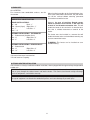
WATER CHEMISTRY
(Corrosive water voids all warranties)
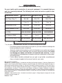
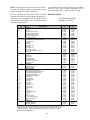
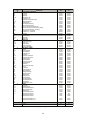
For your health and the protection of your pool equipment, it is essential that your
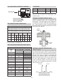
water be chemically balanced. The following levels must be used as a guide for balanced water.
Recommended Level(s)
Water Temp. (Deg. F)
pH
Total Alkalinity (PPM)
Calcium Hardness (PPM)
Salt (PPM)
Free Chlorine (PPM)*
Fiberglass Pools
Fiberglass Spas
Other Pool & Spa
Types
7.3 to 7.4
7.3 to 7.4
7.6 to 7.8
68 to 88
89 to 104
120 to 150
120 to 150
4500 MAXIMUM
4500 MAXIMUM
200 to 300
2 to 3
150 to 200
2 to 3
Total Dissolved Solids (PPM) 3000 MAXIMUM** 3000 MAXIMUM**
* Free Chlorine MUST NOT EXCEED 5 PPM!
68 to 104
80 to 120
200 to 400
4500 MAXIMUM
2 to 3
3000 MAXIMUM**
** In salt water chlorinated pools, the total TDS can be as high as 6000 ppm.
•
•
•
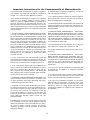
Occasional chemical shock dosing of the pool or spa water should not damage the
heater providing the water is balanced.
Automatic chemical dosing devices and salt chlorinators are usually more efficient
in heated water, unless controlled, they can lead to excessive chlorine level which
can damage your heater, and which is not covered under warranty. A check
valve should be installed between the heater outlet and a chlorinator or other chemical dosing device.
Further advice should be obtained from your pool or spa builder, accredited pool
shop, or chemical supplier for the correct levels for your water.
Rev. 2 reflects the following:
Changes to: Contents on page 3, Introduction and Start-Up Procedure on page 5, Receiving Equipment on
page 9, Loose Plumbing Parts diagram on page 9 (moved from page 30), Florida tie-down diagram on page 13,
Specifications and Dimensions on page 14, Vent/Inlet Termination Clearances on page 15, Direct Vent instructions on page 16, Venting Category Requirements on page 17, Category I installation on pages 19-20, Horizontal
Venting diagrams on page 21, Vertical Direct Vent diagram on page 22, Outdoor Installation on page 23,
Plumbing Connections on page 28, Status and Diagnostics on page 37, Orifice Removal diagram on page 41,
Igniter Removal on page 41, Troubleshooting on page 42, Control Logic flow chart on page 43, Illustrated Parts
List on pages 44-46
Additions: Table and Direct Vent - Horizontal instructions on page 21, Piping diagrams on page 30, Gas and
Air Orifice Selection on page 41
Deletions: None
2