1
Safety • Assembly • Operation • Tips & Techniques • Maintenance • Troubleshooting • Parts Lists • Warranty
A
O
AL
/
/
/
/
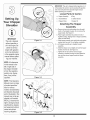
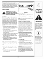
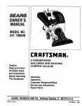
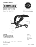
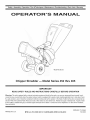
*Model462 Shown
Chipper Shredder-
Model Series 452 thru 465
IMPORTANT
READ SAFETY
RULES AND iNSTRUCTiONS
CAREFULLY
BEFORE
OPERATION
Warning: This unit isequippedwithan internalcombustionengineand shouldnot be usedon or nearany unimprovedforest-covered,brushcoveredor grass-coveredland unlesstheengine'sexhaustsystemis equippedwith a sparkarrestermeetingapplicablelocalor statelaws(if any).
If a sparkarresterisused,it shouldbe maintainedineffectiveworkingorder by the operator.In theState of Californiathe aboveisrequiredbylaw
(Section4442 of the CaliforniaPublicResourcesCode). Otherstatesmay havesimilarlaws.Federallaws applyon federallands.A sparkarrester
for the muffleris availablethroughyour nearestengineauthorizedservicedealeror contactthe servicedepartment,RO. Box361131Cleveland,
Ohio 44136-0019.
PRINTEDIN U.S.A.
MTD LLC, P.O. BOX 361131 CLEVELAND, OHIO 44136-0019
FORMNO.770-100481
7/20/2006
This Operator's
IVlanual is an important
pare and maintain
part of your new chipper
the unit for best performance.
Please
shredder,
it wiil help you assemble,
read and understand
pre=
what it says.
Table of Contents
Customer Support ..............................................
2
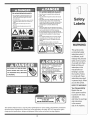
Safety Labels ......................................................
3
Safe Operation
Practices ...................................
4
Setting UpYour Chipper Shredder .................... 6
Operating
Your Chipper Shredder ................... 10
Maintaining Your Chipper Shredder ................
Troubleshooting ................................................
Parts List ...........................................................
Warranty .............................................
12
14
16
Back Cover
Finding and Recording Model Number
f
BEFOREYOU STARTASSEMBLING
YOUR NEW EQUIPMENT,
please locate the model plate on the equipment and copy
the information to the sample model plate providedto the
right. You can locate the model plate by standing behind the
unit and looking down at the frame below the engine. This
informationwill be necessary to use the manufacturer'sweb
site and/or obtain assistance from the Customer Support
Department or an authorizedservice dealer.
Model Number
Serial Number
MTD LLC
®
www, mtdproducts,com
P.O. BOX
361131
CLEVELAND, OH 44136
330-220-4683
800-800-7310
Customer Support
Please
do NOTreturn
purchased,
without
the unit to the retailer from
first contacting
Customer
which it was
Support.
If you have difficulty assembling this product or have any questions regarding the controls, operation, or maintenanceof this
unit, you can seek help from the experts. Choose from the options below:
1. Visit mtdproducts.com.
Click on Yard Machines and then the CustomerSupport menu option.
2. Phone a Customer Support Representative at 1 (800) 800-7310.
3. The engine manufacturer is responsible for all engine-related issues with regards to performance, power-rating,specifications, warranty and service. Please refer to the engine manufacturer's Owner's/Operator's Manual, packedseparately with
your unit, for more information.
2
TO AVOID SERIOUS iNJURY:
TO AVOID SERIOUS iNJURY:
•
•
Do not operate on uneven ground where unit is
unstable,
other hard surfaces
To avoid a fire hazard, keep leaves, grass, and other
combustible
muffler,
materials
•
Keep children
•
operation,
Wear approved
the owner's
Keep all shields
attached.
•
Keep
hands,
Shredder
away from hot engine and
Chute
feet, face,
starting
these
injury
in place
clothing
Chipper
the engine
inside
personal
safety glasses, gloves and ear
before
and guards
Hopper,
while
blades
and others away from area of
manual(s)
and
unit,
•
since objects can ricochet
and cause injury,
•
Read
using
Do not operate on pavement, gravel or
and long hair
Chute
if contacted.
out of
and Discharge
is running,
openings
and securely
will
Rotating
cause
Material
cutting
serious
being
processed
protection.
may bounce
from
back
the discharge
may be pulled
•
Do not place
from
inlet
chute.
sucked
into the inlet
branches
the large
Shredder
diameter
should
openings
or be thrown
Long hair or loose
clothing
openings.
over 1/2 inch diameter
Hopper.
be placed
Branches
into
over 1/2 inch in
in the Small
Chipper
Chute.
•
If the
chipped
immediately
moving
shredder
shut
jams or becomes
off the engine
clogged,
and wait for all
parts
to come to a complete
install
remove,
stop
before
clearing.
•
Do not
discharge
is running.
screen
Blade
adjust,
or service
or any other part
contact
while
the
the engine
I
can occur.
J
• ROTATING
AND
FEET
MACHINE
ROTATING CUTTING BLADES.
CUTTING
IS
THE
OF OPENINGS WHILE MACHINE
CHUTE
OF OPENING
THIS
MACHINE
DEFLECTOR
PROPERLY
INSTALLED
WITH
HAND
THE
HANDS
WHILE
RUNNING.
• DO NOT OPERATE
KEEP HANDS AND FEET OUT
BLADES.KEEP
OUT
AND
UNLESS
HAS BEEN
IS SECURED
KNOBS.
iS RUNNING.
WARNING
This symbol points
out importantsafety
instructionswhich, if
not followed,could
endangerthe personal
safety and/or property
of yourselfand others.
Read and follow all
instructionsin this
manual beforeattemptingto operate
this machine. Failure
to comply with these
instructionsmay result
in personalinjury.When
you see this symbol.
HEED ITS WARNING!
Your Responsibility
Restrict the use
of this power machine
to persons who read,
understand
and follow the warnings
and instructions
in this manual
and onthe machine.
This OperatorsManualcoversa rangeof productspecificationsfor variousmodels.Characteristicsand features
discussedand/orillustrated
inthis manualmay not be applicableto all models.MTDLLC reservesthe rightto
changeproductspecifications,designsand equipmentwithoutnoticeand withoutincurring
obligation.
3
WARNING: Engine Exhaust, some of its constituents, and certain vehicle components contain or emit chemicals known to State of Californiato cause cancer and
birth defects or other reproductiveharm.
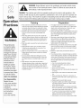
DANGER: This machine was built to be operated according to the rules for safe operation in this
manual. As with any type of power equipment, carelessness or error on the part of the operator can
result in serious injury. This machine is capable of amputating hands and feet and throwing objects.
Failureto observe the following safety instructions
could result in serious injuryor death.
Training
WARNING
This symbol points
out importantsafety
instructionswhich, if
not followed,could
endangerthe personal
i safety and/or property
I ofyourselfand others.
Read and follow all
instructionsin this
manual beforeattemptingto operate
i this machine. Failure
I to complywith these
instructionsmay result
i in personalinjury.When
you see this symbol.
Preparation
1. Read,understand,and followall instructionson the machine andin the manual(s)beforeattemptingto assemble
andoperate.Keepthis manualina safe placefor future
and regularreferenceand for orderingreplacementparts.
2. Be familiarwith all controls andtheir proper operation.
Know howto stop the machineanddisengagethem
quickly.
3. Neverallow childrenunder 16years oldto operatethis
machine.Children 16years old andovershould read and
understandthe operationinstructionsandsafety rulesin
this manualand shouldbe trainedand supervisedbya
parent.
4. Neverallow adultsto operatethis machinewithoutproper
instruction.
1. Thoroughlyinspectthe area wherethe equipmentis to
be used. Removeall rocks,bottles,cans, or otherforeign
objectswhichcould be pickedup or thrown andcause
personalinjury or damageto the machine.
2. Alwayswearsafetyglasses or safetygogglesduringoperation or whileperformingan adjustmentor repair,to protect
eyes. Thrownobjectswhich ricochetcan cause serious
injury to the eyes.
3. Wearsturdy, rough-soledworkshoesand close-fitting
slacksandshirts. Loosefitting clothesor jewelrycan be
caught in movableparts. Neveroperatethis machine
in barefeet or sandals.Wear leatherwork gloves when
feedingmaterialin the chipperchute.
4. Beforestarting,check all bolts and screwsfor propertightnessto be surethe machineis in safe workingcondition.
Also,visuallyinspectmachinefor any damageat frequent
intervals.
5. Keepbystanders,helpers,pets,and childrenat least
75 feetfrom the machinewhile it is in operation.Stop
machineif anyoneentersthe area.
6. Neverrunan engineindoorsor in a poorlyventilatedarea.
Engineexhaustcontainscarbon monoxide,an odorless
anddeadly gas.
7. Do not put hands andfeet near rotatingparts or in the
feedingchambersanddischargeopening.Contactwith
the rotatingimpellercan amputatefingers,hands,and
feet.
5. Maintainor replacesafetyandinstructionslabels,as
necessary.
6. Toavoid personalinjury or propertydamage use extreme
care inhandlinggasoline.Gasolineis extremelyflammable
andthe vaporsare explosive.Serious personalinjury can
occurwhen gasolineis spilledon yourself or your clothes
whichcan ignite.Washyour skinand changeclothes
immediately.
a. Useonly an approvedgasolinecontainer.
b. Extinguishall cigarettes,cigars, pipes,andother
sourcesof ignition.
c. Neverfuel machineindoors.
8. Neverattemptto unclogeither the feed intakeor
dischargeopening, removeor empty bag,or inspectand
repairthe machinewhilethe engineis running.Shutthe
engineoff andwait until all moving partshavecometo a
completestop. Disconnectthe spark plug wire andground
it againstthe engine.
d. Neverremovegas cap or add fuel whilethe engineis hot
or running.
e. Allow engineto coolat leasttwo minutesbeforerefueling.
f. Neveroverfill fuel tank. Filltank to no morethan 1/2
i HEED ITS WARNING!
inch belowbottomof filler neckto providespacefor fuel
expansion.
g. Replacegasolinecap andtighten securely.
h. If gasolineis spilled,wipe it off the engine and equipment. Movemachineto another area.Wait 5 minutes
i Your Responsibility
Restrict the use
of this power machine
to personswho read.
i understand
beforestartingthe engine.
i. Neverstorethe machineor fuel containerinside where
there is an openflame, spark,or pilot light (e.g.furnace,
waterheater,spaceheater,clothesdryer,etc.)
j. Toreducea fire hazard,keepmachinefree of grass,
leaves,or otherdebris build-up.Clean up oil or fuel
spillageand removeanyfuel soakeddebris.
k. Allow machineto cool at least5 minutesbeforestoring.
and follow the warnings
and instructions
i in this manual
and on the machine.
4
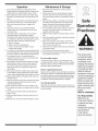
Operation
Maintenance
& Storage
1. Donot put hands andfeet near rotatingpartsor in the
feedingchambersand dischargeopening.Contactwith the
rotatingimpellercan amputatefingers, hands,andfeet.
2. Beforestartingthe machine,makesurethe chipperchute,
feed intake,and cuttingchamberare empty andfree of all
debris.
1. Nevertamper withsafetydevices.Checktheir proper
operationregularly.
2. Checkbolts and screwsfor propertightness at frequent
intervalsto keepthe machinein safe workingcondition.
Also,visuallyinspectmachinefor any damageand repair,if
needed.
3. Thoroughlyinspectall materialto be shreddedand remove
any metal,rocks,bottles, cans, or otherforeignobjects
which could causepersonalinjury or damageto the
machine.
3. Beforecleaning,repairing,or inspecting,stop the engine
andmakecertain the impellerand all movingparts have
stopped.Disconnectthe sparkplug wire and groundit
againstthe engine to preventunintendedstarting.
4. Do not changethe engine governorsettingsor overspeed
the engine.The governorcontrols the maximumsafe
operatingspeed of the engine.
5. Maintainor replacesafetyandinstructionlabels, as necessary.
6. Followthis manualforsafe loading,unloading,transporting,
andstorageof this machine.
7. Neverstorethe machineor fuel containerinside where
thereis an openflame, sparkor pilot lightsuch as a water
heater,furnace, clothesdryer,etc.
8. Alwaysreferto the operator'smanualfor proper instructions
on off-seasonstorage.
9. If the fuel tank has to be drained,do this outdoors.
10. Observeproper disposallaws andregulationsfor gas, oil,
etc. to protectthe environment.
4. f it becomesnecessaryto pushmaterialthroughthe
shredderhopper, usea smalldiameterstick. Do not use
your hands or feet.
5. f the impeller strikesa foreignobject or if your machine
should start makingan unusual noiseor vibration,
immediatelyshut the engine off. Allow the impellerto come
to a completestop.Disconnectthe sparkplug wire, ground
it againstthe engine andperformthe followingsteps:
a. Inspectfor damage.
b. Repairor replaceany damagedparts.
c. Checkfor any loose partsand tightento assure
continuedsafe operation.
6. Donot allow an accumulationof processedmaterialto build
up inthe dischargearea.This can preventproperdischarge
and result in kickbackof materialthrough the feed opening.
7. Donot attemptto shred or chip materiallargerthan
specifiedon the machineor inthis manual.Personalinjury
or machinedamagecould result.
8. Neverattemptto unclogeitherthe feed intakeor discharge
openingwhilethe engine is running.Shutthe engine off,
wait until all movingparts havestopped,disconnectthe
spark plug wire andground it againstthe engine before
clearing debris.
9. Neveroperate withoutthe shredderhopper,chipperchute,
or chute deflectorproperlyattachedto the machine.Never
empty or changedischargebagwhilethe engine is running.
10. Keepall guards,deflectorsand safetydevices in placeand
operatingproperly.
11. Keepyourface andbody backand to the side ofthe chipper
chute whilefeedingmaterialintothe machineto avoid
accidental kickbackinjuries.
12. Neveroperatethis machinewithoutgoodvisibility or light.
13. Donot operate this machineon a paved,gravelor non-level
surface.
Do not modify
engine
Toavoid seriousinjury or death,do not modifyengine inany
way.Tamperingwiththe governorsettingcan leadto a runaway
engineandcauseit to operateat unsafespeeds.Nevertamper
withfactorysettingof enginegovernor.
Notice
regarding
Emissions
Engineswhichare certifiedto complywithCaliforniaandfederal
EPAemissionregulationsfor SORE(SmallOff RoadEquipment)
arecertified to operateon regularunleadedgasoline,and may
includethe followingemissioncontrolsystems:EngineModification (EM)andThreeWayCatalyst(TWO)if so equipped.
Your Responsibility
Restrictthe useof this powermachineto personswho read,understandand followthe warningsand instructionsin this manual
andon the machine.
14. Donot operate this machinewhile underthe influenceof
alcohol or drugs.
15. Mufflerandengine becomehot andcan causea burn.Do
not touch.
Practices
WARNING
This symbol points
out important safety
instructions, which if
not followed, could
endanger the personal
safety and/or property
of yourself and others.
Read and follow all
instructions in this manual before attempting to
operate this machine.
Failureto comply with
these instructions may
result in personal injury.
When you see this
symbol.
HEED
iT S WARNING!
Your Responsibility
Restrictthe use
16. Neverpickup or carry machinewhilethe engine is running.
of this power machine
to persons who read.
understand
and follow the warnings
and instructions
in this manua
and on the machine.
5
IMPORTANT:This unit is shippedwithoutgasolineor oil
in theengine.Be certainto serviceenginewith gasoline
and oil as instructedin the separateengine manual
beforeoperatingyour machine.
Loose Parts In Carton
a. HopperAssembly
d. Bag
b. Chute Deflector
e. SafetyGlasses
c. ChipperChute
f. EngineOil
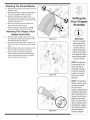
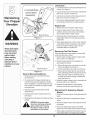
Attaching The Hopper
Shredder
Assembly
1. a. Removesix hexnuts and washersfrom the weld
studson the impellerhousing.Donot removethe
supportplate. See Figure3-1.
b. Placehopperassemblyinto positionin front of
impellerhousing,aligningholesin hopperassembly
collarwith weldstuds.
IMPORTANT
This unit is shipped
without gasoline or
oil in the engine. Be
certainto service
Figure 3=1
c. Slide hopperassemblyontoweld studsand replace
washersand hex nuts.Donot tightencompletely.
2. a. Lift hopperassemblyup to impellerbracket
assembly.
b. Slide the releaserod out slightlyto hookthe hopper
bracketontothe rod.See Figure3-2.
c. Tightenthe six hexnuts that securehopper
assemblyto impellerhousingand alsotightenthe
hex nutsthat secure hopperbracketto hopper
assembly.
enginewith gasoline
and oil as instructed
in the separate engine
manual before operating your machine.
NOTE: All references
in this manual to the
left or right side of
the chipper shredder
is from the operating
i position only. Exceptions if any will be
specified.
Figure 3-2
NOTE: This Operators
i Manual covers a range
of product specifications for various
models. Characteristics
and featuresdiscussed
and/or illustrated in this
manual may not be applicable to all models.
MTD LLC reserves the
right to change product
specifications, designs
and equipment without
notice and without
=ncurringobligation.
Figure 3-3
6
Attaching The Chute Deflector
3. a. Removethe wingknobs fromeach sideof the lower
impellerhousing.
b. Removethe hexlock nut,spacers,andhex boltfrom
the topof theimpellerhousing.SeeFigure3-3.
4. a. Align the chutedeflectorin positionon the
dischargeopeningand inserthex boltwith spacer
throughhingeon chutedeflector(spacersfit inside
of hinges).See Figure314.
b. Placesecondspaceroverhex bolt insideother
hingeand securewith hex lock nut.
c. Securebothsides of chutedeflectorto impeller
housingusingwingknobspreviouslyremoved.
Your Chipper
Sh redder
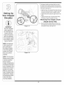
Attaching The Chipper Chute
(Model Series 460)
5. a. Removethe threecuppedwashersand hexnuts
from weldstudsaroundthe openingon the side of
the impellerhousing.See Figure3-5.
b. Removethe hexbolts,flat washers,and lock nuts
from the two holeson the upperend of the support
brace.
IMPORTANT
Figure 3-4
This unit is shipped
without gasolineor
oil in the engine. Be
certain to service
6. a. Align the chipperchute overthe weldstuds, sothe
slot in the bottomof the chuteis facing down.
b. Securechipperchute with the threecupped
washers(cuppedsideagainstthe chipperchute)
and hexnuts previouslyremoved.Do nottighten
the nuts at this time. See Figure316.
enginewith gasoline
and oil as instructed
in the separate engine
manual before operating your machine.
NOTE: All references
in this manual to the
left or right side of
the chipper shredder
is from the operating
position only. Exceptions, if any, will be
specified.
Fgure 3=5
f
/
/
/
/
/
/
/
/J
/
//
/
/
//
..........
1,/
/
/
/
NOTE: This Operators
Manual covers a range
of product specifications for various
models. Characteristics
and features discussed
and/or illustrated in this
manual may not be applicable to all models.
MTD LLC reservesthe
/
Figure 3=6
7
right to change product
specifications, designs
and equipmentwithout
notice and without
_ncurringobligation.
7. Thechippershredderwas shippedwith one end of
the supportbracealreadysecuredto the lowerframe.
Loosenbut do not removethebolts securingthe brace
to the frame.See Figure3-7.
/
/
/
/
ji
//
//
///
a. Align the holesin the chutewith the holes in the top
of the braceand attachbraceto chipperchute with
hardwarepreviouslyremoved.Tightensecurely.
b. Tightenthe bolts securingthe supportbraceto the
frame.
//
Setting u p
/
c. Tightenthe three nutson the weldstudsholding
the chipperchuteto the impellerhousing.
Attaching The Chipper
Chute
(Model Series 450)
MPORTANT
8. a. Removethethreecuppedwashersand hex nuts
fromweld studsaroundtheopeningon the sideof
the impellerhousing.See Figure3-8.
Figure 3-7
This unitis shipped
without gasoline or
oil in the enginelae
certain to serv ce
engine with gasoline
in
an_Joil as instructed
the separate engine
manUaI beforeope!ating your machine
NOTE: All references
in this manual tOthe
left or right side of
the chipper shredder
iSfrom the operating
position onlyl Excep;
tions, if any, w Ii be
specified:
Figure 3=8
i
NOTE: This Operators
ManUalcovers a range
Of product specifiCa:
tions for Various
mode!s:Characteristics
and featuresdiscussed
andior ilUstratedinthiS
manual may not be ap,
plicable toali models!
MTD LLC reservesthe
right to change product
specificationsidesigns
andequipment w thout
notice and without
incurring obligationl
8
f
9. a. Align the chipperchute overthe weldstuds, sothe
slot in the bottomof the chuteis facing down.
b. Securechipperchute with the threecupped
washers(cuppedsideagainstthe chipperchute)
and hexnuts previouslyremoved.Tightenthe nuts
at this time.See Figure3-9.
/
/
Attaching The Bag
Setting
10.Toattachthe bag:
Up
YourChippe
a. Placethe openingof the bag completelyover the
chute deflector.
Shredder
b. Pullon the drawstringuntilthe bag is tight around
chute deflectoropening.
c. Clipdrawstringback on itself,tight againstchute
deflectorto secureintoposition.See Figure3-10.
Figure 3=9
MPORTANT
This unit iSshipped
without gaso ine or
oilin the enginelBe
Certain to service
engine with gasoline
and Oilas instrUCted
the separate engine
manual before operati
ing your machine:
NOTE: All references
this manual tothe
Figure 3=10
left or right side of
the chipper shredder
is from the operating
position only. Excepi
tions, if any. will be
specified:
NOTE: This OPerators
ManUal covers a range
of product specifiCa,
tions for Various
models: CharacteriStics
and features discussed
and/or iilustrated in this
manual may not be ap.
plicable to all models:
MTD LLC reservesthe
right to Changeproduct
specifications; designs
and equipment without
notice and w thout
incurr ng Obligationl
9
m
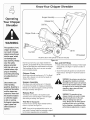
Know Your Chipper
Shredder
HopperAssembly
ReleaseRod
Oil Fillt
Chipper Chute
WARNING
I
i
i
i
The operation of any
chipper shredder
can result in foreign
objects being thrown
intothe eyes, which
can damage your
eyes severely. Always
wear the safety
glasses provided
with this unit or eye
shields before chipping or shredding
and while performing
any adjustments or
repairs.
Oil Fill
1 If Equipped
*Model462 Shownwith 0
(Not included)
Figure 4-1
Now thatyou haveset up your chippershredderfor
operation,get aquaintedwith its controlsand features.
Theseare describedbelowand illustratedon this page.
This knowledgewillallowyou to use yournewequipmentto its fullestpotential.
Chipper
Gas and Oil Fill-Up
1. Checkoil leveland add oil if necessary.Followengine
manualfor this. See Figure4-1 abovefor locationof
the oil fill.
2. Servicethe enginewith gasolineas instructedin the
enginemanual. See Figure4-1 abovefor locationof
gasfill.
Chute
Allowstwigsand small branchesup to 3" (2"for Model
Series450) indiameterto be fed intothe impellerfor
chipping.See Figure4-1.
I Use extreme care
Hopper
when handling
gasoline. Gasoline is
extremely flammable
i and the vapors are
explosive. Neverfuel
i the machine indoors
' or while the engine
Allowleavesand small branchesup to 1/2diameter
to be fed into theimpellerforchippingand shredding.
Materialcan be rakedinto hopperassemblyby lowering
the hopperassembly.See Figure4-1.
is hot or running.
I Extinguish cigarettes,
cigars, pipes and
other sources of
ignition.
Release
Assembly
WARNING: Useextremecarewhen handling gasoline.Gasoline is extremely
flammable and the vapors are explosive.
Never fuel the machine indoorsor while
the engineis hot or running.Extinguish
cigarettes, cigars, pipesand other
sources of ignition.
Rod
WARNING:The operation of any
chippershredder canresultin foreign
objects being thrown intothe eyes,
which can damage your eyes severely. Always wear the safety glasses
providedwith this unit or eye shields
before chippingor shredding and while
performingany adjustments or repairs.
The releaserod is locatedon the impellerbracket
assemblyand it is usedto releaseor lock the hopper
whenraisingor lowering.See Figure4-1.
Tow Bar (if Equipped)
Use thetow bar to tow the chippershredderbehinda
tractorto a jobsite.See Figure4-1.
NOTE:If your unit isnotequippedwith a tow bar,you
maycontact CustomerSupportas instructedon page2
for information
regardingpriceand availability.
10
This OperatorsManualcoversa rangeof product
f
specificationsforvariousmodels.Characteristicsand features discussedand/or illustratedin this manualmay not
_
_
be applicableto all models.MTDLLCreservesthe right
to changeproductspecifications,designsand equipment
withoutnoticeand withoutincurringobligation.
._1__
Starting
Engine
/,
_
_
-=]
|
|
_11111_
_
(
WARNING:Never run the engine
indoorsor in a poorlyventilatedarea.
Figure 4=2
Engine exhaustcontainscarbonmonoxStopping
Engine
ide,an odorless and deadly gas.
1. Movethrottlecontrolleverto STOPor OFF position.
IMPORTANT:Becausethis manualcoversseveral
differentmodelunits,differentstartinginstructions
may
applyto your particularengine.Someenginesmay have
a fuel petcock,some maynot. Someenginesmay have
On/Off switches,othermaynot. Someunits will utilizea
choke system,whileotherswill requirepriming. These
factorsdependon what makeand modelenginecomes
with your particularunit. For these reasons,pleaserefer
to the engineoperator'smanualforthe correctstarting
procedure.
1. Attachspark plugwire to spark plug.Makecertain
the metalcap on theend of the sparkplug isfastened
securelyoverthe metal tip on the spark plug.
2. Engines with choke lever:
Movechokeleveron engineto CHOKEposition.(A
warm enginemay not requirechoking).
Engines with primer:
2. Disconnectspark plug wirefrom spark plugand
groundagainstthe engine.
NOTE:See yourenginemanualpackedwith your unit
for moredetailedinstructions.
Using The Chipper
Shredder
Yardwastesuchas leavesand pine needlescan be
rakedup throughthe hopperassemblyfor shredding.
After materialhas been shreddedbythe flail blades
on the impellerassembly,itwill be dischargedout of
openingor into catcherbag. Donot attemptto shred
or chip anymaterialotherthanvegetationfoundina
normalyard (i.e. branches,leaves,twigs, etc.)Avoid
fibrousplantssuch as tomatovines until theyare
thoroughlydriedout. Twigsand small branchesup to 3"
(2" for ModelSeries450) indiameter can be fed into
the chipperchute.
Lowering
The Hopper Assembly
Primeengineas instructed
inseparateengine manual. 1. With one handgraspthe handleat the top of the
hopperassemblyand lift slightly.
3. The throttlecontrolleveris locatedon the engine.
Moveenginethrottlecontrol leverto FASTor START 2. With theother handpull out on the releaserod
position.See Figure4-2.
and lowerthe hopperassemblyto the ground.See
Figure4-1.
4. Graspstarterhandleand pull ropeout slowlyuntil
engine reachesstart of compressioncycle(rope will
pull slightlyharderat this point).
NOTE:A noisewill be heard whenfindingthe start of
the compressioncycle. This noiseis causedby theflails
and fingers,whichare partof the shreddingmechanism,
and it shouldbe expecteduntilthe impellerreachesfull
speed.
5. Pull ropewith a rapid,continuous,fullarm stroke.
Keepa firm grip on starterhandle.Let roperewind
slowly.
6. Repeatthe previousstepsuntilenginefires.When
engine starts,movechokecontrol(if equipped)
graduallyto RUNposition.
To Empty
Bag
1. Un-clipdrawstringand loosenbag from chute
deflectoropening.
2. Emptybag and reattachto the dischargechute
opening.Pull on the drawstringuntilthe bag istight
aroundthe chuteopeningand clip thedrawstring
tight againstthechute deflector.
IMPORTANT:The flailscreen islocatedinsidethe
housingin the dischargearea.If theflail screen
becomesclogged,removeand cleanas instructedin
SECTION5: MAINTAININGYOURCHIPPERSHREDDER.Forbest performance,it isalso important
to keep
the chipperblade sharp.
11
Never run the engine
indoors orin a poorly
ventilated area: Engine
exhaust contains
carbon monoxide, an
)dorless and deadly
NOTE: A noisewill be
heardwhenfindingthestart
ofthe compressioncycle.
This noiseis causedby
theflails and fingers,which
are part ofthe shredding
mechanism,and it should
beexpecteduntilthe impeler reachesfull speed.
Lubrication
1. Lubricatethe releaserodand springwith lightoil once
a season.See Figure5-1.
2. Lubricatethe pivot pointson the hopperassemblywith
lightoil oncea season.See Figure5-1.
points before
reassembly.
3. Lubricatethe pivot pointson the dischargechute with
lightoil oncea season.See Figure5-1.
4. Followtheaccompanyingengine manualfor lubrication scheduleand instruction
for engine lubrication.
Your Chipper
Shredder
Engine Care
1. Maintainoil levelas instructedin enginemanual.
2. Serviceair cleanerevery25 hoursundernormal
conditions.Cleaneveryfew hoursunderextremely
dustyconditions.Referto engine manual.
*Model462 Shown
3. Cleansparkplug and resetthegap once a season.
Checkenginemanualfor correctplugtype and gap
specifications.
Figure 5-1
4. Cleanengineregularlywith a cloth or brush. Keepthe
coolingsystem(blowerhousingarea) cleanto permit
properair circulation.Removeall grass,dirt and
combustibledebrisfrom mufflerarea.
;//
Always stop engine,
disconnect spark
plug, and ground
against engine
before cleaning,
lubricatingor
doing any kind of
maintenance on your
machine.
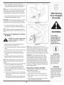
Removing
The Flail Screen
If the dischargearea becomesclogged,removetheflail
screenand cleanarea as follows:
1. Stopthe engineand makecertain the chippershredder has cometo a completestop.
2. Disconnectsparkplug wirefrom sparkplug and
groundagainsttheengine.
3. a. Removethe bagand two wingknobson eachside
of the chutedeflector.See Figure5-2.
b. Lift the chute deflectorup to keepitoutof theway.
c. Removethetwo hairpinclips fromeach clevispin
whichextendthroughthe housingand removepins.
d. Removetheflail screenfrom insidethe housing
and cleanthe screenby scrapingor washingwith
water.See Figure5-2.
4. Reinstallthe screen,makingcertainto reassemblethe
flail screenwith thecurve sidedown.
/*Model462 Shown
Figure 5-2
General
Recommendations
1. Alwaysobservesafetyruleswhen performing
anymaintenance.
2. Thewarrantyon this chippershredderdoes not
coveritemsthat havebeen subjectedto operator
abuseor negligence.Toreceivefull valuefrom warranty,operatormustmaintainthe chippershredder
as instructedhere.
5. Reattachthe chute deflectorwith the hardware
previouslyremovedand connectthe bag to unit.
3. Changingof engine-governedspeedwill void
enginewarranty.
Sharpening
Blades
4. All adjustmentsshouldbe checkedat leastonce
eachseason.
1. Disconnectthe spark plugwire and groundagainstthe
engine.
5. Periodicallycheckall fastenersand makesurethese
are tight.
2. Removetheflail screenas instructed
inthe previous
section.
_
disconnectspark plug, and ground
WARNING:Alwaysstopengine,
against engine before cleaning,
lubricating or doingany kind of
maintenanceon your machine.
Or Replacing
Chipper
3. Removethechipperchute by removingthree hexnuts
and washers.
4. Removethechipperchute supportbrace(Model
Series460) fromthe frame by removingthe hexbolts.
5. Rotateimpeller
assemblyby hand untilyoulocate one
of two chipperbladesinthe chipperchute opening.
12
6. Removethe blade by removingthe internalhex
screws,lockwashers,and hexnuts which secureit to
the impeller.Retainthe hardware.See Figure5-3.
NOTE: Usea 3/16"hex key (Allen)wrenchon the outside
of the blade and a 1/2" box(or socket)wrenchon the
insideof the impeller.HoldtheAllen wrenchstationary
and rotatethe box(or socket)wrenchto loosenthe nut.
Your Chipper
,redder
7. Installa replacementblade (PartNo. 781-0490)with
the hardwareremovedearlieror sharpen.
i
IMPORTANT:Whensharpeningthe blade,protecthands
by usinggloves.Followthe originalangle of grind and
make sureto removean equalamountfrom eachblade.
Figure 5-3
8. To replacethe otherblade,rotatethe impellerto
exposethe secondblade and repeatthe stepsabove.
NOTE: Makecertainbladesare reassembledwith the
sharpedge facing upward.Torquehardwareto 250- 300
in. Ibs.
Sharpening
Or Replacing
der Blade
_
WARi ,,ING
The Shred-
The impeller S
chipper blades and
shredder blade are
sharp: Wear leather
work gloves to
protect your hands;
are
sharp. Wearleatherwork
gloves to
ARNING:The
impeller'schipperblades
protectyour hands.
1. Stop theengineand makecertainthat all moving
parts havecome to a completestop.
Figure 5-4
2. Disconnectthe sparkplug wireand groundagainstthe NOTE:Use a 3/16" hexkey (Allen)wrenchon the
outsideof the shredderbladeand a 1/2" box(or socket)
engine.
wrenchon the insideof the shredderblade.Holdthe
3. Lowerthe hopperassemblyand block up the housing.
Allenwrench stationaryand rotatethe box (or socket)
4. Removethe six hex locknuts and flat washers
wrenchto loosenthenut. Usecautionwhen removing
from the weldstudson theflail housing.Retainthe
the bladeto avoidcontactingthe weldstudson housing.
hardware.
IMPORTANT:Whensharpeningthe blade,follow
5. Carefullyseparatethe hopperassemblyfromthe
the originalangleof grind as a guide.It is extremely
impellerassemblyand removethe support plate.
importantthat eachcuttingedge receivesan equal
amountof grindingto preventan unbalancedblade.
NOTE:When reassemblingthe supportplate,make
An unbalancedbladewill causeexcessivevibration
certain theembossedtab facesinwardtowardsthe
whenrotatingat high speedsand maycause damage
impeller.
to the unit. Theblade can be testedby balancingit on a
6. Removethe two wing knobsand cuppedwashersthat
screwdriveror nail. Removemetalfrom the heavyside
securethe chute deflectorand raisethe chute.
until it is balancedevenly.
7. Inserta 1/2"or 3/4" diameterpipethroughthe flail
screen intothe impellerto keepit fromturningor
Storing Your Chipper Shredder
removethe flail screenand inserta pieceof wood into Thefollowingstepsshouldbe takento prepareyour
the chuteopening.
chippershredderfor storage.
8. a. Removethe two internalhex screws,lock washers, 1. Cleantheequipmentthoroughly.
and hexlock nuts which securethe shredderblade
to the impeller.
b. Removethe hexbolt, lock washer,and flat washer
to completelyfree shredderblade.See Figure5-4.
2. Wipeequipmentwith an oiled ragto preventrust.
3. Referto engine manualforcorrectengine storage
instructions.
4. Storeunitin a clean,dry area. Donot store nextto
corrosivematerialssuchas fertilizer.
13
IMPORTANT
Makecertainchipper
blades are reassem:
bled with the sharp
edge facing upwar&
Torquehardwareto
250,300 in. Ibs.
iMPORTANT
When reasSemblingthe
shredder blade,tighten
center bolt tObetween
550 and 700 ini,lb&
andthe twoOutboltsto
between 250 and 350
in.4b&
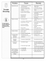
Problem
Cause
Enaine
f.,
ailsto Start I
Remedy
Throttle levernotin correctStarting
i thrott,
Move
post on (f equ pped)
e everto FASTor
STARTpost on
2, Sparkp!ugwire disconnected,
2,
Connectwire tospark p!ug,
choke
notincHoKE
position
(if
cHOKE
equipped):
poSiti0nl
Fueltank emptyor Sta!efuel.
&Engine not pdmed(if equipped)Prime
tank with clean,freShgasolinel
engineas .instructedin
6 Faut
ark _
ysp
P g:
6 ceanadjuStgap 0rrepace
Blocked
fuel
81Engine flooded,
Engineruns erratic
.
For repairs beyond
the minor adjustments
listed here, contact
an authorized service
Engine overheats
•
Occasional skips
(hesitates) at
high speed
Unit does not
CleanfueI
&Wait a few minutesto Festart,but
do not prme:
Sparkplug wireloose.
1. Connectand tightenspark
plug wire.
2. Unit runningon CHOKE(if equipped).
2. Movechokeleverto OFF position.
3. Blockedfuelline or stale fuel.
3. Cleanfuel line;fill tank with clean,
fresh gasoline.
4. Ventin gas cap plugged.
4. Clearvent.
5. Wateror dirt in fuel system.
5. Drainfuel tank. Refillwith
fresh fuel.
6. Dirty air cleaner.
6. Referto enginemanual.
7. Carburetorout of adjustment.
7. See authorizedservicedealer.
1. Engineoil levellow.
_
1. Fillcrankcasewith properoil.
2. Dirty air cleaner.
3. Carburetornotadjustedproperly.
I
2. Referto enginemanual,
3. Seeauthorizedservicedealer.
1. Sparkplug gap tooclose.
1. Adjustgap to .030".
2. Carburetoridle mixtureadjustment
improperlyset.
2. See authorizedservicedealer.
1. Chutedeflectorclogged.
1. Stop engineimmediatelyand
disconnectsparkplug wire.Clean
flail screenand insideof discharge
opening.
2. Foreignobject lodgedin impeller.
2. Stop engineand disconnectspark
plug wire. Removelodgedobject.
3. Lowengine RPM.
3. Alwaysrun engineat full throttle.
discharge
Rate of discharge
slows considerably
or composition of
I
discharged material
changes
I
,
!
1 Lowengine RPM.
2. Chipperbladedul.
1. Alwaysrun engineat fullthrottle.
I
I
14
2. Replacechipperbladeor seeyour
authorzed servce dea er.
NOTES
Use this page to make notes and write down important information.
15
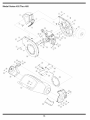
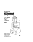
Model
Series 452 Thru 465
j_
i
•¢/i
16
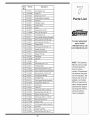
Ref.
No,
PartNo.
Description
1.
736-0217
Lock Washer,3/8
2.
714-0149B
CotterPin
3.
681-0048
WingKnob5/16-18
4.
681-0094
ChuteDeflectorAssembly
5.
711-0835
ClevisPin
6.
781-0457
ShredderScreen
7.
726-0211
U-Nut5/16-18
8.
750-0793
Spacer
9.
712-3027
Hex Lock Nut 1/4-20
10. 712-3004A
Hex Lock Nut5/16-18
11. 736-0119
Lock Washer5/16
12. 681-0117
InnerImpellerHousingAssembly
13. 710-3025
Hex CapScrew5/16-18x.625
14. 710-0157
Hex CapScrew5/16-24x.75
15. 781-0490
ChipperBlade
16. 710-1054
Hex CapScrew5/16-24x 1.0
17. 681-0030
impellerAssembly
18. 712-0411
Hex Lock Nut5/16-24
££NUIN£
_FACTORY
PARTS
TO order replacement
parts, contact
1.8oo:8oo.7alo
or
www:mtaprOauc
19. 781-0735
RetainerPinClip
20.
719-0329
Flail Blade
21.
711-0833B
ClevisPin
22.
715-0166
Pin
23.
736-0247
Flat Washer3/8 x 1.25
24.
742-0571
ShredderBlade
25.
710-1254
Hex CapScrew3/8-24 x 2.25
26.
681-0004A
Outerlmpeller HousingAssembly
27.
710-0825
Hex CapScrew 1/4-20x 3.75
28.
781-0515
FrontSupportBracket
29.
781-0574
ShredderPlate
30.
681-0104
RearHopperBracketAssembly
31.
732-0306
CompressionSpring 1.75
32.
736-0117
FlatWasher
right to change product
33.
714-0104
CotterPin
34.
736-0264
FlatWasher.330ID x.630OD
specifications;designs
and equipmentwithout
35.
710-0376
Hex CapScrew5/16-18x 1.0
36.
748-0453
Spacer,.375ID x2.50 LG
37.
736-0362
Flat Washer.320ID x 1.25OD
38.
712-0429
Hex Lock Nut5/16-18
39.
731-1710A
HopperCollar
40.
681-0123
Front HopperBracketAssembly
41.
711-1128
Lock Rod
42.
731-1707
HopperAssembly
43.
710-3008
Hex CapScrew5/16-18x.75
NOTE: This Operators
ManUalcovers a range
of product specifiCa;
tions for Various
models:CharaCteristics
and featuresd iscussed
and/or illustrated in this
manual may not be ap*
plicable to all model&
MTD LLC reservesthe
notice and without
incurring obligation
i__ _ii_: !_ iiiiiiiii_!_
_ii _iii_ __i_i
i_
17
i
_ii_
_ii_
i
i
i
i _
i
i
i
i
i
i
i
i
i
ii
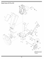
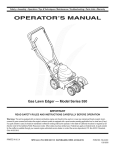
iVlodel Series 452 Thru 465
(16
1 ft ModelSeries454 & 464
:l:{ ModelSeries452 & 462
* If Equipped
18
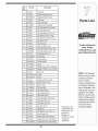
Ref.
No.
Part No.
Description
1.
728-0175
Pop Rivet
2.
731-1899
ChipperShredderChute
681-0095{H
ChipperShredderChute
3.
735-0249
Chute Flap
4.
781-0633
Chute FlapStrip
5.
681-0068A
6.
710-0751
Hex CapScrew 1/4 -20x.620
7.
712-3027
Hex Lock Nut 1/4-20
8.
710-0106
Hex CapScrew 1/4-20x 1.25
9.
736-0173
FlatWasher.28ID x.74OD
. ChipperChuteAssembly
10. 736-0242
Bell Washer.340ID x.872OD
11. 712-3010
Hex Nut5/16-18
12. 749-1004
SupportBrace
13. 712-3004A
Hex Lock Nut5/16-18
14. 710-0805_{
Hex CapScrew5/16-18x 1.50
710-3180tt
Hex CapScrew5/16-18x 1.75
15. 736-0170
Bell Washer5/16x 1.0
16. 736-0366tH
FlatWasher
17. 738-0814_:{
AxieAssembly
738-0813tH
Axle Assembly
18. 750-0786_{
Spacer
19. 734-1600_:{
WheelComp.,10.0x 2.5 Plastic
20.
734-1845t{{
WheelComplete,10.0x 4.0 Gray
726-0214
PushCap
=iTS
To order replacement
parts, contact
1-800-800-7310 or visit
www.mtdproducts.com
NOTE: This Operators
Manual covers a range
of product specifications for various
models. Characteristics
and features discussed
and/or illustrated in this
21. 681-0184A_{H Frame
681-0183Att
Frame
22.
736-0451
Washer,.320IDx.93 OD
23.
710-0502A
Screw,3/8-16x 1.250
24.
737-0195A{H
ElbowFitting
25.
737-0298tt
Oil DrainPipe
26.
737-0132tt
Oil DrainEndCap
27. 681-0133"
TongueHitchMount
28. 681-0134A*
BaseHitch Mount
29.
710-3001"
Hex CapScrew,3/8-16x.88
30.
711-0299"
ClevisPin,.625x2.4
31.
711-0835"
ClevisPin,.50x 4.62
32.
712-3017"
Hex Nut,3/8-16
• 33.
732-0194"
Spring Pin
34.
736-0133"
Flat Washer,.411
x 1.25x 1.0
35.
736-0169"
Lock Washer,3/8
--
723-0400
SafetyGlasses(Not Shown)
--
664-04022
ChipperBagAss'y(Not Shown)
--
664-04023tt_
ChipperBagAss'y(Not Shown)
19
manual may not be applicable to all models.
MTD LLC reserves the
right to change product
specifications, designs
and equipmentwithout
notice and without
t ModelSeries464
tt Model464G Only
_1ModelSeries462
{ Models452
HModels454
AModels462 & 464D
* If Equipped
Models465
incurring obligation.
MANUFACTURER'S
LiMiTED WARRANTY
The limitedwarrantyset forth belowisgivenby MTDLLCwith respect
to newmerchandisepurchasedand usedin the UnitedStates,its
possessionsand territories.
"MTD"warrantsthis productagainstdefectsin materialand workmanshipfor a periodof two (2) years commencingon the date of original
purchaseand will, at its option,repairor replace,freeof charge,any
part foundto be defectiveinmaterialsor workmanship.This limitedwarranty shallonlyapply if this product hasbeen operatedand maintained
inaccordancewith the Operator'sManualfurnishedwith the product,
and has notbeen subjectto misuse,abuse,commercialuse, neglect,
accident,impropermaintenance,alteration,vandalism,theft, fire, water,
or damagebecauseof otherperil or naturaldisaster.Damageresulting
fromthe installationor useof any part, accessoryor attachmentnot
approvedby MTDfor use with the product(s)coveredbythis manual
willvoid yourwarrantyas to any resultingdamage.
Normalwearparts are warrantedto be free fromdefects in materialand
workmanshipfor a periodof thirty (30) days fromthe dateof purchase.
Normalwearparts include,butare notlimitedto itemssuch as: batteries,belts,blades,blade adapters,grass bags, riderdeck wheels,seats,
snowthrowerskid shoes,shaveplates,auger spiralrubberand tires.
HOW TO OBTAIN SERVICE: Warranty service is available, WITH
PROOF OF PURCHASE, through your local authorized service
dealer. To locate the dealer in your area, check your Yellow Pages,
or contact MTD LLC at RO. Box 361131,Cleveland, Ohio 441360019, or call 1-800-800-7310 or 1-330-220-4683 or log on to our
Web site at www.mtdproducts.com.
This limitedwarrantydoesnot providecoverageinthe followingcases:
a. Theengineor componentparts thereof.These itemsmaycarry a
separatemanufacturer'swarranty.Referto applicablemanufacturer's
warrantyfor termsand conditions.
b. Log splitterpumps,valves,and cylindershavea separateone year
warranty.
c. Routinemaintenanceitemssuch as lubricants,filters, blade
sharpening,tune-ups,brakeadjustments,clutchadjustments,deck
adjustments,and normaldeteriorationof the exteriorfinish due to
useor exposure.
FOR
e. MTDdoesnot extendanywarrantyfor productssoldor exported
outsideof the UnitedStates,its possessionsand territories,except
those soldthroughMTD'sauthorizedchannelsof export distribution.
f. Replacementparts that are notgenuine MTDparts.
g. Transportationchargesand servicecalls.
No impliedwarranty,includingany impliedwarranty of merchantabilityof fitness for a particular purpose,applies after the
applicable periodof express written warranty above as to the
parts as identified.No otherexpresswarranty, whetherwrittenor
oral, except as mentioned above, givenby any personor entity,
includinga dealeror retailer, with respect to any product,shall
bind MTD.Duringthe periodof the warranty,the exclusiveremedy
is repairor replacementof the productas set forth above.
The provisionsas set forth in this warrantyprovidethe sole and
exclusiveremedy arising from the sale. MTDshallnot be liable
for incidentalor consequentialloss or damage including,without
limitation, expensesincurredfor substituteor replacementlawn
careservicesor for rentalexpensesto temporarily replacea
warranted product.
Somestatesdo notallowthe exclusionor limitationof incidentalor
consequentialdamages,or limitationson howlong an impliedwarranty
lasts, sothe aboveexclusionsor limitationsmaynot applyto you.
In no event shallrecoveryof any kindbe greaterthanthe amountof the
purchasepriceof the productsold.Alterationof safety features of
the productshallvoid this warranty. Youassumethe risk and liability
for loss,damage,or injuryto you and yourpropertyand/orto others and
theirpropertyarisingout of the misuseor inabilityto usethe product.
This limitedwarrantyshallnot extendto anyoneotherthan theoriginal
purchaseror to the personfor whomitwas purchasedas a gift.
HOWSTATELAWRELATESTOTHIS WARRANTY: This limited
warrantygivesyou specificlegal rights,and youmay alsohaveother
rightswhich vary from stateto state.
IMPORTANT:OwnermustpresentOriginal Proofof Purchaseto obtain
warrantycoverage.
d. Servicecompletedby someoneotherthanan authorizedservice
dealer.
IViTD LLC, P.O. BOX 361131 CLEVELAND, OHiO 44136-0019;
Phone: 1=800=800-7310, 1-330=220-4683