1
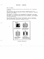
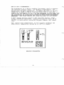
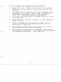
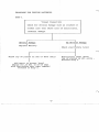
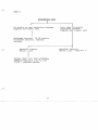
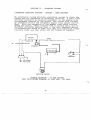
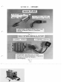
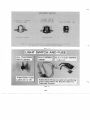
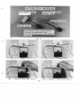
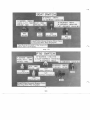
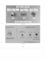
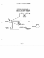
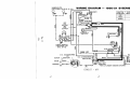
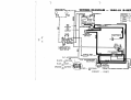
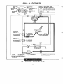
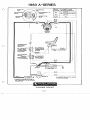
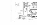
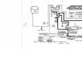
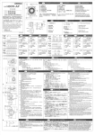
ELECTRICAL SERVICE MANUAL WHEEL HORSE
Table of Contents – Page 1 of 1
INTRODUCTION
SECTION I - BATTERY
HOW IT WORKS HOW TO USE A HYDROMETER HOW TO PREPARE A DRY CHARGED BATTERY FOR SERVICE PROCEDURE FOR TESTING BATTERIES
SECTION II - CHARGING SYSTEM
ALTERNATOR CHARGING SYSTEMS - KOHLER - ONAN ENGINES
BRIGGS & STRATTON ALTERNATOR SYSTEMS
TECUMSEH 7 AMP REGULATED CHARGING SYSTEM (LT-1032)
SECTION III - COMPONENTS
SECTION IV - WIRING DIAGRAMS
SECTION V - TROUBLE-SHOOTING EXAMPLES
CTRICAL SERVICE
PART NO. 810291 R 2
Printed in U.S.A. 0385
INTRODUCTION
This manualcovers A and B-Series 1980-83 and C-Series
1978-83Tractors. For 1984 and
later tractors, refer to Section 18
in Parts and Service manuals for electrical components
and wiring diagrams.
CONTENTS
Page
..........................
How It Works. ...............................
How To Use a Hydrometer.. . . . . . . . . . . . . . . . . . .
How To Prepare a DryCharged Battery. . . . . . . . . .
Procedure
For
Testing
Batteries. ...............
SECTION I I CHARGING SYSTEM.. ...............
SECTION I - BATTERY..
AlternatorChargingSystems
Onan Engines
- Kohler . . . . . . . . . .
SECTION III - COMPONENTS.
1-5
1
2
3
4
6-10
6
....................
11-16
SECTION IV WIRING DIAGRAMS.. . . . . . . . . . . . . . 17-40
SECTION V-TROUBLESHOOTING EXAMPLES.. ..... 41-47
-
I
SECTION I
.
HOW IT WORKS
A battery
- BATTERY
-
produces electricity as the result
of a chemical
reaction.
The sulfuric acid in the electrolyte combines
with the
positive and negative plates
to form anew chemical compound
called lead sulfate.
The amount of sulfuric acid consumed by the platesprois
portional to the amountof electricityproduced. Therefore,
the more electricity produced the less' sulfuric acid remains
in the electrolyte.
i
The gradual weakeningof the electrolyte letsus measure,
with a hydrometer, the amountof unused acid in the water,
and thus how much potential energy is left.
DOWN
C
FU
HLAGLRO
YGI N
ED
G
Acid in water gives electrolyte
specific gravity of 1.265.
DISCHARGED
As battery discharges, acid
begins to lodge in plates.
Specific gravity drops.
END/LIFE
Battery half discharged.
Acid almost entirely
in
Moreacid in plates, less inplates.leavingweakelectroelectrolyte.
Starting
lyte
behind.
Specific
gravity
lower, almost that of water.
failure likely.
BATTERY CHEMISTRY
-1-
HOW TOUSE
A HYDROMETER
-
The hydrometer is a direct-reading instrument to
used
measure
the specific gravity (Spg). In reading a hydrometer, the
barrel must be held vertically.
To apply the test it is only
necessary to draw
a sample of electrolyte from a cell and
jiggle the hydrometer to be sure
the indicator is floating free
and record the indicated Spg.DO N O TM A I N T A I NL I Q U I DL E V E LI N
T H E HYDROMETER BY SQUEEZINGTHE BULB A ST H I SG I V E SI N A C C U R A T E
READINGS.
The float shouldnot touch any
part o f the barrel.
A full charge battery equals
1 . 2 6 5 specific
gravity(Spg)
unless otherwise specified. Replace battery if there is
50
(0.050) or more points variation between highest and lowest
cell.
Spg. varieswith temperature, so for' correct readings the
electrolyte temperature should be 60°F
at or higher.
High
float
(left) means
high
specific gravity.
Low
float
means low specific gravity.
READING
Correct method of
reading hydrometer.
Eye onlevel with
liquid surface. Disregard
curvature
liquid
of
against
glass parts. b o not
t i It
hydrometer
while
reading.
Keep float vertical.
HYDROMETER
HOW TO PREPARE A DRY CHARGED BATTERY FOR SERVICE
-
A.
Remove
ventcaps.
Remove o r destroy any sealingdevice
which may havebeen used t o close or r e s t r i c t t h e v e n t
openings.
B.
F i l l each c e l l of t h eb a t t e r y w i t h 1 . 2 6 5 s p e c i f i c g r a v i t y
e l e c t r o l y t e t o theproperlevel.'Note:Temperature
of
battery electrolyte at
time of f i l l i n g should be
above 60 F . Never f i l l b a t t e r y in the vehicle.
C.
F i l l w i t he l e c t r o l y t eu n t i l
of f i l l i n g t u b e .
D.
A l l o w b a t t e r y t o s t a n df o r
beforecharging.
E.
Place on chargerfor
1 0 minutes a t a 1 5 amp r a t e .I f
a fastratechargerisnotavailablechargefor
one
h a l f hour a t a 7 amp r a t e .
F.
Aftercharging,
check a c i d l e v e l s i n a l l c e l l s
with acid t o the t o p of s p l i t ring ledge.
G.
I n s t a l lb a t t e r yi nt h ev e h i c l e .
Remember, alwaysconnect
t h en e g a t i v et e r m i n a ll a s t .A f t e rb a t t e r y
has been placed
i ns e r v i c e add onlywater.
Do not add acid.
i t becomes v i s i b l e a t
bottom
15 minutes a t room temperature
and f i l l
PROCEDURE FOR TESTING BATTERIES
STEP 1
V i s u a lI n s p e c t i o n
Check f o r o b v i o u s
damage s u c h a s c r a c k e d o r
broken case t h a t shows l o s s o f e l e c t r o l y t e ,
t e r m i n a l damage.
Obvious Damage
No Obvious Damage
I
Replace
Check e l e c t r o l y t e l e v e l
Below t o po fp l a t e si no n eo r
I
more c e l l sE l e c t r o l y t e
l e v e l above
t o p of p l a t e s i n a l l c e l l s Proceed S t e p 2 .
Add water t o p r o p e r level
Charge f o r 1 5 min. @ 15-25 amps
withnon-safetyvent
caps removed
2.
P r o c e e dt oS t e p
-4-
STEP 2
HYDROMETER TEST
5 0 points ormore variation
highest and lowest cell
between
Less than 5 0 points
variation between
highest and lowest cell
Recharge battery. If 5 0 points
variation persists, replace
battery
Specific Gravity
Above 1 . 2 2 5 - Battery OK
Specific Gravity
Below 1 . 2 2 5
Charge untilall cells are at
least 1.225 if unable to obtain
Specific Gravity 1 . 2 2 5 in all
cells - replace battery
-5 -
SECTION II - CHARGING SYSTEM
ALTERNATOR CHARGING SYSTEMS- KOHLER
-
ONAN ENGINES
The alternator system provides electrical energy
to charge the
battery and for operationof accessory circuits. A solid state
rectifier-regulator is mounted externally
on the engineor on
the equipment powered by the engine.
The system also includes
an alternator-stator and permanent magnet ring inside
fly-the
wheel. With the exceptionof the magnet ringwhich revolves
around the stator, these systemshave no
moving parts and are
therefore virtually service free
- - the only required service
is an occasional check to make sure that all electrical connections are tight and that wires are not frayed
or cracked.
FUSE
AC
ALTERNATOROUTPUT
SOLE
I
I
I
REGULATOR
RECTIFIER
IGNITION SWITCH
TROUBLE SHOOTING - 15 AMP SYSTEM
TEST WITH ENGINE RUNNING AT
3400 RPM - NO LOAD
-6-
Condition: No Charge to Battery
Test A - With B+ cable connected, check
B+ (at terminal on rectifierregulator) to groundwith DC
volt meter. If 13.8 volts or
higher, place minimum loadof
5* amps on battery to reduce
voltage:
A-1
A-2
-
If charge rate increases
-
If charge rate doesnot
increase
Possible Fault/Remedy
A - 1 - Indicates alternator
System OK, battery
was fully charged
4-2 - Check for defective
stator, orrectifierregulator (Test B)
Test B - Unplug leads at rectifier
regulator, connect VOM
(Multimeter) across ACleads,
check AC voltage
Possible Fault/Remedy
B-1
-
If less than 28 volts
B-1 - Defective stator,
replace.
B-2 - If more than 28 volts
B-2
-
Defective rectifierregulator; replace
with new unit.
Condition: Battery Continuously
Charges atHigh Rate
Test C - Check B+ to ground with DC
volt meter
Possible Fault/Remedy
-
C-1
-
If over 14.7 volts
C-1
C-2
-
If under 14.7
C-2 - Alternator system OK.
Battery unable to hold
charge. Check specific gravityof battery.
Replace if necessary.
Rectifier-regulator
not functioning
properly.Replace.
*Turn lights on or simulate load by placing 2.5
a OHM
100 Watt resistor across battery
terminals.
-7-
Briggs & Stratton Alternator Systems
A
& RR-Series electric start engines have a single
DC output
alternator used for battery charging only.
The dual circuit
alternator usedon B, LT & GT-Series and some C-Series tractors
is actually two separate alternators.A single ringof magnets
inside the flywheel supplies the
magnetic field for both of them.
One alternator uses a solid state rectifier and provides battery
charging current. The other alternator feeds alternating current
directly to the lights. Since the two are electrically
independent, use of the lights
does not reduce the charge entering
the battery.
Current for the lights is available as long as the engine is
running. The output depends upon the engine speed.,
s o the
brightness of the light changes with the engine speed.
is unregulated
The current from the battery charging alternator
and is rated at3 amps. The output rises from2 amps at 2400
RPM to 3 amps at 3600 RPM, and uses less than. 2 of a horsepower.
There is one external connection.The battery charging current
connection is made through one terminal
of a two connector plug.
Current for lights is available at the second terminal of this
plug. The plug is polarized to prevent improper connections.
The return circuit for both alternators is through ground
to the
engine block.
1. Checking Dual Circuit Alternator
A. Testing Alternator Charging Output
Install an ammeter in Series
with charging lead.
Start engine. Ammeter should indicate output.
The charge range is dependent upon the condition
of the battery. If ammeter shows no charge, or
shows a discharge, test stator and diode.
ENGINE RUNNING
3000 RPM
-8-
B. Testing for Short in Alternator System
Disconnect charging lead from
battery, and connect charge
lead test lamp in Series between battery and charge lead.
DO NOT START ENGINE. Test lamp should not light. If it
does light, stator charging lead is shorted or diode is
defective. Disconnect charge lead connector at alternator.
If test light doesnot go out, the dire leading back to the
battery is shorted. If light goes out, diode is defective.
(See section for testing
diode).
C. Testing Diode
Disconnect charge lead plug from charge lead. Using
multimeter set on resistance
scale, 'check diode
by attaching one meter lead to red stator.
wire
lead
(a needle may
be used to pierce stator lead
wire insulation). Touch the
other multimeter lead to diode pin in plastic
connector,
then reverse meter leads.The meter should show continuity
in one direction only. If meter shows a reading in both
directions or does not show continuity in either direction,
the diode is defective and must be replaced.
D.
Testing Stator Charging Coils
Remove blower housing, flywheel etc. and examine red lead
wire for cuts, damaged insulation or obvious short on
leads; if bare spots cannot be repaired replace stator.
Stator should also be checked for continuity
follows:
as
Use multimeter seton resistance scale. Touch one meter
lead to stator laminations, touch the other meter lead to
red stator charge lead wire. (Pierce red
wire insulation
with a needle to insure meter leadcontact). Meter should
show continuity.
Next remove screw
which attaches stator ground wires to
stator laminations, Be certainground wire does not touch
laminations and repeat previous test. Meter should not
show
continuity. If meter does not show continuity in first test
or shows continuity during second
test, stator is defective
and must be replaced.
Note: Discoloration of stator coils doesnot mean stator
is defective. A shorted diode will pass battery current
through stator coils to
ground, which discolors coils due
to heat. Replacing diode would normally restore alternator
without replacing stator.
-9-
Tecumseh 7 Amp Regulated Charging System (LT-1032)
theamp
The Tecumseh 7 amp charging system is similar to 15
system used on Kohler and Onan engines. Follow the test
procedure for these engines,with the following exceptions:
Test B
-
AC voltage value shouldbe at least
21 VAC. The blower shroud must be
removed, the rectifier/regulator
moved to place it outside the
housing,
and the blower housing reinstalled
to make this test.
Test C - Do not perform this test. If AC
voltage check isOK and battery is
not being charged, replace the
rectifier/regulator.
-10-
SECTION I I I - COMPONENTS
3
B S E R I E S 1980-82
C-SERIES 1978-83
LT,GT - SERIES 1982
A,B,LT,GT-SERIES
1983
Fig. 3
/LIGHT SWITCH AND FUSE
ALL TRACTORS
WITH LIGHTS
FUNCTION: Turns
Lights On or Off.
B & CSERIES
1978-81
B, C, LT & GTSERIES
1982/83
FUNCTION: Protects Light Circuit Wiring
From Heat When An Electric Short or
Overload Occur$.
Fig. 4
-12-
Fig. 5
NORMAL POSITION
Fig. 8
Normallyclosed
(N/C) S w i t c h
Fig. 9
Normallyclosed
(N/C)
Switch
F i g . 10
Fig. 11
-14-
C SERIES - 1981
AUTOMATIC
I
FUNCTION: Prevents Engine From
Starting When Pedal Is Released.
TRANSMISSION SWITCH
RELAY SWITCH
6 - S E R I E S1 9 8 1
A-SERIES1981
1982
A - 5 1 1 9A8- 8
2 1 , A - 1 19 18 3
I
N/O
FUNCTION: Grounds Engine
Magneto When D.C. Current To
Internal Coil is Cut Off.
N/O (SILVER)
N/C (PINK)
(WIDE
TERMINAL:
N/C
(NARROW. TERMINALS)
FUNCTION: Prevents Engine From Starting
With Transmission In Gear.
Fig. 13
-15-
SECTION IV- WIRING DIAGRAMS
WIRING DIAGRAM
1981 A-51 and A-81R
RECOIL START RIDER
IGNITION
SWITCH
INTERLOCK
MODULE
RED
ENGINE
PTO
INTERLOCK
SWITCH
INTERLOCK
SWITCH
Fig. 14
-17-
F i g . 15
-18-
I
K
a
I
IK
a
I-
W
W
Fig, 17
-20-
I
f
W
W
a
(3
Fig. 18
-21-
a
F i g . 19
-22-
W
W
a
(3
Fig. 20
-23-
K
W
aI
E
K
a
m
a
K
ow
m
A
K
(3
w
w
K
(3
a
+ +
+
+
K
w
Fig. 2 1
-24-
W
K
Fig. 22
-25-
K
w
+
+
K
Fig. 23
-26-
Fig. 2 4
-27-
a
W
I
I
+
+
a
I
I
Fig. 25
-28-
Fig. 26
-29-
W
1983 A-SERIES
RUN
START
B+S
BLUE
IGNITION
SWITCH
I
W
m
TRANSMISSION
INTERLOCK
CONTACTS
CLOSED WHEN
TRANSMISSION
IN NEUTRAL
PTO INTERLOCK
SWITCH
CONTACTS
CLOSED WHEN
TRANSMISSION
CLOSEDWHEN
SEATUNOCCUPIED
ORANGE
ORANGE
CONTACTS
CLOSED WHEN
BLUE
ALTERNATOR
WHITE
ALL WIRES BLACK WITH COLOR
STRIPE AS SHOWN.
DC OUTPUT
*ENGINE CHARGING SYSTEM IS
NOT DESIGNED FOR ACCESSORY
OPERATION.
START CIRCUIT
A-SERIES
ELECTRICAL
SWITCH
POSITION BETWEEN TERMINALS
START
TAN
ACCESSORIES* (A)
UNUSED
MAGNETO
BLUE
WHITE
IGNITION
SWITCH
TRANSMISSION
INTERLOCK
SWITCH
CONTACTS
CLOSED WHEN
TRANSMISSION
IN GEAR
CONTACTS
CLOSEDWHEN
TRANSMISSION
IN NEUTRAL
BLACK
CLOSED WHEN
ORANGE
ORANGE
PTO
INTERLOCK
CONTACTS
CLOSED WHEN
CONTACTS
CLOSED WHEN
PTO DISENGAGED
MAGNETO
WHITE
ALL WIRES BLACK WITH COLOR
STRIPE AS SHOWN.
*ENGINE CHARGING SYSTEM IS
NOT DESIGNED FOR ACCESSORY
OPERATION.
KILL CIRCUIT
PTO ENGAGED
1983 A-SERIES
ACCESSORIES* (A)
SWITCH
ELECTRICAL
POSITION BETWEEN TERMINALS
G+
(SWITCHCASE GROUNDED)RUN
START
B+S
BLUE
IGNITION
SWITCH
TRANSMISSION
INTERLOCK
SWITCHCONTACTS
CLOSED WHEN
TRANSMISSION
CLOSED WHEN
TRANSMISSION
IN NEUTRAL
SEAT UNOCCUPIED
ORANGE
PTO
INTERLOCK
SWITCH
CONTACTS
CLOSED WHEN
CONTACTS
CLOSED WHEN
PTO
DISENGAGED
I
BLUE
BLUE
WHITE
ALTERNATOR
DC
'ENGINE CHARGING SYSTEM IS
NOT DESIGNED FOR ACCESSORY
OPERATION.
KILL CIRCUIT TRANS.
ALL WIRES BLACK WITH COLOR
STRIPE AS SHOWN.
'IN GEAR
1983 A-SERIES
ELECTRICAL
BETWEEN TERMINALS
START
TAN
ACCESSORIES* (A)
UNUSED
(SWITCH CASE GROUNDED)
MAGNETO
BLUE
START
BLUE
IGNITION
SWITCH
a
TRANSMISSION
INTERLOCK
CONTACTS
CLOSED WHEN
TRANSMISSION
IN NEUTRAL
PTO
INTERLOCK
SWITCH
CLOSED WHEN
PTO DISENGAGED
SWITCH
CONTACTS
CLOSED WHEN
TRANSMISSION
IN GEAR
ORANGE
CONTACTSCLOSED WHEN
ORANGE
CONTACTS
CLOSED WHEN
PTO ENGAGED
BLUE
C D
WHITE
ALTERNATOR
MAGNETO
'
OUTPUT
*ENGINE CHARGING SYSTEM IS
NOT DESIGNED FOR ACCESSORY
OPERATION.
ALL WIRES BLACK WITH COLOR
STRIPE AS SHOWN.
CHARGINGCIRCUIT
-33-
Fig. 27
-34-
+
I-
a
IK
Fig. 2 8
-35-
W
I
I
I
W
K
W
w
K
Fig.
30
-37-
K
W
a
d
K
Fig.
31
-38-
Fig. 32
-39-
I
K
-40-
SECTION V
PROBLEM 1:
-
TROUBLE-SHOOTING EXAMPLES
Customer Complaint - Every time he uses his C-85
(1981) tractor it won't start. He has to put
jumper cables on the battery
and jump start the
tractor.
F i g . 34
STEP 1:
Visually Inspect A l l Connections:
A.
B.
Blown Fuse
Loose or Broken Wires
Fig. 35
Step 2:
Check the Battery
A.
B.
C.
Visual inspection
Charge the battery
Hydrometer test
Fig. 36
Step 3:
If battery checks out OK and tractor will
now start with fully charged batterycheck the following:
A.
Start unit and check charging
sys
tems
1.
Ammeter for Charge
Fig. 37
-42-
Step 4:
If no charge indicated at the Ammeter, check
voltage at battery terminals- with the
engine running at 3 / 4 to full throttle, D.C.
voltage should show increase to approximately
14 volts D . C .
Fig. 38
Step 5:
No voltage increase - unplug the rectifier/
regulator - with the meter set for A.C.
28 volts
current the meter should read around
AC -
- if less than 28 volts A.C. - Defective
stator, replace.
- if more than 28 volts A.C.
- Defective
rectifier/regulator, replace withnew
unit.
F i g . 39
-43-
PROBLEM 2:
Customer Complaint - 1981 GT-2500 Anniversary
Special - the engine cranks over but won't start.
After some investigation you find the battery is
in good condition.
Fig. 40
Step 1:
Always check the obvious
A.
-
Blown Fuse
B.
Loose
or Broken Wire Connection
Fig. 41
-44-
Step 2:
Unplug the magneto wire from the engine and
try starting.
A.
If the unit starts continueon to
Step 3 .
i
NOTE - Remember you will have to
reconnect the magneto wire
to kill the engine.
B.
If it doesn't start, the problem is
with the engine, not the wiring
harness.
1. Check the engine for spark - if
spark, there is some carburetor
or mechanical problem.
2.
If no spark - check breaker
points and magneto.
Fig. 42
Step 3:
If the engine started with the magneto wire
removed, we have to assume we are having
problemsinourkillrelaycircuit.First
connect a test light or meter to the black
wire located on the ignition switch
(I-terminal). Try starting the unit. If
we show voltage continue to Step
4.
Fig. 4 3
Step 4: Inspect the connections
to the kill relay and
PTO interlock switch. Make sure the kill
relay has a good ground.
F i g . 44
F i g . 45
S t e p 5:
Connect a t e s tl i g h to rm e t e rt ot h e
kill
r e l a y ( s t e r m i n a lv i o l e tw i r e )t r ys t a r t i n g
theunit,if
you show c u r r e n t - r e p l a c e t h e
killrelayswitch.
Fig. 46
Product information and
specifications
are
shown
herein
as
of the
time
of
printing.
Wheel Horse
Products,
Inc.
reserves
the
right to
changeproductspecifications.designsandstandardequipmentwithout
noticeandwithoutincurring
obligation.
WHEEL HORSE WORK HORSE
Iawn&gardentractors
by