1
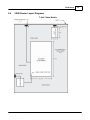
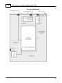
Vision Engravers and Routers
PRE-Installation Guide
© 2014 Vision Engraving & Routing Systems
Revised: 8/4/2014
Vision Engravers and Routers
PRE-Installation Guide
© 2014 Vision Engraving & Routing Systems
All rights reserved. No parts of this work may be reproduced in any form or by any means - graphic, electronic, or
mechanical, including photocopying, recording, taping, or information storage and retrieval systems - without the written
permission of the publisher.
Products that are referred to in this document may be either trademarks and/or registered trademarks of the respective
owners. The publisher and the author make no claim to these trademarks.
While every precaution has been taken in the preparation of this document, the publisher and the author assume no
responsibility for errors or omissions, or for damages resulting from the use of information contained in this document or
from the use of programs and source code that may accompany it. In no event shall the publisher and the author be liable
for any loss of profit or any other commercial damage caused or alleged to have been caused directly or indirectly by this
document.
Revised: 8/4/2014
Contents
3
Table of Contents
Part I Introduction and Computer Requirements
4
Part II General Electrical and Facility Requirements
by Model
5
Part III Express and VE-810
6
1 Express
...................................................................................................................................
Layout Diagram
7
2 VE-810...................................................................................................................................
Layout Diagram
7
Part IV Phoenix 1212
8
1 Phoenix
...................................................................................................................................
1212 Layout Diagram
9
Part V 16 Series and 24 Series Engravers
10
1 1612 and
...................................................................................................................................
1624 Engraver Layout Diagram
11
2 2424 and
...................................................................................................................................
2448 Engraver Layout Diagram
12
Part VI 16 Series and 25 Series Routers
13
1 High Frequency
...................................................................................................................................
Router Head
13
2 Engraving
...................................................................................................................................
Head
16
3 1624R...................................................................................................................................
Router Layout Diagram
18
4 2525 and
...................................................................................................................................
2550 Router Layout Diagrams
19
Part VII MAX and MAX PRO
22
1 MAX and
...................................................................................................................................
MAX PRO Layout Diagram
23
Part VIII VR48 Router
24
1 Requirements
................................................................................................................................... 25
2 Wiring
...................................................................................................................................
Connections
28
3 Vacuum
...................................................................................................................................
Pump Connections - Vacuum Table Models Only
32
4 VR48...................................................................................................................................
Router Layout Diagrams
33
© 2014 Vision Engraving & Routing Systems
3
4
1
Vision Engravers and Routers PRE-Installation Guide
Introduction and Computer Requirements
This guide contains information to prepare the new owner of a Vision Engraver or
Router for the proper installation of their machine. It is the customer's responsibility to
read through this guide and make sure the work area, electrical and computer
requirements are met prior to the arrival of a representative from Vision for the
scheduled installation/machine orientation date (Training NOT included with Vision
Express machines). If for any reason, there are questions about these requirements,
please call your Vision representative ASAP to either clarify these requirements, or
reschedule the installation date. If Vision personnel arrive and all pre-installation
requirements are not complete, there will be an additional charge of $750/day
while waiting.
IT IS HIGHLY RECOMMENDED THAT THE COMPUTER USED TO OPERATE
THE VISION ENGRAVER OR ROUTER BE CONNECTED TO THE INTERNET.
THIS ALLOWS THE USER TO ALLOW VISION'S TECHNICAL SUPPORT TO
ACCESS THE MACHINE AND TROUBLESHOOT IF NECESSARY.
Minimum System
Requirements
CPU:
Hard Drive:
RAM:
Operating System:
Ports:
Suggested System
Requirements
CPU:
Hard Drive:
RAM:
Operating System:
Ports:
Dual Core (2.0GHz or higher)
120 GB
1GB + OS Requirements
Windows 8 32/64 Bit
Windows 7 32/64 Bit
Windows Vista 32/64 Bit
Windows XP 32 Bit
USB port for security dongle
Local or network Ethernet port to connect machine
Quad Core (3.0 GHz or higher)
250 GB (or more)
4GB + OS Requirements
Windows 8 32/64 Bit
Windows 7 32/64 Bit
USB port for security dongle
Local or network Ethernet port to connect machine
Please skip the the appropriate section for details regarding your specific machine.
© 2014 Vision Engraving & Routing Systems
Introduction and Computer Requirements
2
5
General Electrical and Facility Requirements by Model
Machine Model
Requirements
Express, VE-810, 1612, 1624 Engraver, 2424, 2448, One 110 VAC 15 Amp, or One 220 VAC 10
MAX and MAX Pro
Amp Single Phase
1624R, 2525 and 2550 Router - T-Slot Table
With High Frequency Router Head
One 110 VAC 15 Amp, or One 220 VAC 10
Amp Single Phase
AND One 220 VAC 30 Amp Single Phase
With Engraving Head
One 110 VAC 15 Amp, or One 220 VAC 10
Amp Single Phase
With NSK High Frequency Spindle
Two 110 VAC 15 Amp, or Two 220 VAC 10
Amp Single Phase
2550 Router with Vacuum Table
With High Frequency Router Head
One 110 VAC 15 Amp, or One 220 VAC 10
Amp Single Phase
AND One 220 VAC 30 Amp Single Phase
AND One 220 VAC 30 Amp 3 Phase
With Engraving Head
One 110 VAC 15 Amp, or One 220 VAC 10
Amp Single Phase
AND One 220 VAC 30 Amp 3 Phase
With NSK High Frequency Spindle
Two 110 VAC 15 Amp, or Two 220 VAC 10
Amp Single Phase
AND One 220 VAC 30 Amp 3 Phase
VR48 Router - T-Slot Table
One 220 VAC 50 Amp Single Phase
AND One 220 VAC 20 Amp Single Phase
VR48 Router - Vacuum Table
One 220 VAC 50 Amp Single Phase
AND One 220 VAC 20 Amp Single Phase
AND One 220 VAC 40 Amp 3 Phase
Optional Equipment
Vacuum Chip Removal System
Optional Equipment Requiring Compressed Air
Supply
UNIST Misting System
NSK High Frequency Spindle
One 110 VAC 15 Amp
Clean Dry Compressed Air Supply 60 - 90
PSI
Clean Dry Compressed Air Supply 1 SCFM
@ 40 PSI
NOTE: In addition to the above requirements a 110 VAC standard outlet will be required to run the
computer.
© 2014 Vision Engraving & Routing Systems
6
3
Vision Engravers and Routers PRE-Installation Guide
Express and VE-810
Vision Express and VE-810 Connections
On the rear of the Vision Express and VE810, there are three connection ports. The power port, the
Ethernet port and the remote on/off port for the optional Vacuum Chip Removal System.
Vision Express (rear view)
For the Vision Express: Connect the power supply cable to a 110 - 220 VAC source, then connect the
power supply plug into the port on the back of the machine. Plug the Ethernet cable into the Ethernet
port.
Vision VE810 (rear view)
For the VE810: Connect the power cable to a 110 - 220 VAC source, then plug the power cable into the
port on the back of the machine. Plug the Ethernet cable into the Ethernet port.
© 2014 Vision Engraving & Routing Systems
Express and VE-810
3.1
Express Layout Diagram
3.2
VE-810 Layout Diagram
© 2014 Vision Engraving & Routing Systems
7
8
4
Vision Engravers and Routers PRE-Installation Guide
Phoenix 1212
Phoenix 1212 Engraver/Series 4 Controller Connections
There is only one connection port on the Phoenix 1212. It is a 25 pin Table Cable port on the left side
of the machine. All other connections on the machine's controller are listed below.
1. The engraver's Pendant is connected to the Pendant cable port.
2. The Ethernet Cable from your computer, hub or network is connected to the Ethernet port.
3. The Table Cable connects from 25 pin connector on the engraver to the Table port.
4. The Power Cable connects a 110 - 220 VAC electrical source to the controller and powers the
controller, table and spindle.
Note: If your machine is equipped with the optional Vacuum Chip Removal System, a remote On/Off
cable is connected to the controller to automatically turn the vacuum pump on and off when the job is
being run.
© 2014 Vision Engraving & Routing Systems
Phoenix 1212
4.1
Phoenix 1212 Layout Diagram
© 2014 Vision Engraving & Routing Systems
9
10
5
Vision Engravers and Routers PRE-Installation Guide
16 Series and 24 Series Engravers
16 and 24 Series Engraver/Series 4 Controller Connections
1. The engraver's Pendant is connected to the Pendant cable port.
2. The Ethernet Cable from your computer, hub or network is connected to the Ethernet port.
3. The Auxiliary Table Cable is used on the 24 Series engraver ONLY.
4. The Table Cable connects from 25 pin connector on the engraver to the Table port.
5. The Spindle Cable connects to the Spindle port.
6. The Power Cable connects a 110 - 220 VAC electrical source to the controller and powers the
controller, table and spindle.
7. If your machine is equipped with the optional Vacuum Chip Removal System, a remote On/Off cable
is connected to the controller to automatically turn the vacuum pump on and off when the job is being
run.
8. *If your machine is equipped with the optional NSK High Frequency Spindle, an second 25 pin
connector will be included with your controller. The NSK Spindle is controlled by the NSK Spindle Cable
connected to this port. NOTE - the Spindle Cable to the standard engraving motor will not be used in this
configuration.
Series 4 Pendant and Controller
© 2014 Vision Engraving & Routing Systems
16 Series and 24 Series Engravers
5.1
1612 and 1624 Engraver Layout Diagram
© 2014 Vision Engraving & Routing Systems
11
12
5.2
Vision Engravers and Routers PRE-Installation Guide
2424 and 2448 Engraver Layout Diagram
© 2014 Vision Engraving & Routing Systems
16 Series and 24 Series Engravers
6
16 Series and 25 Series Routers
6.1
High Frequency Router Head
13
High Frequency Router Head Wiring Connections
1. The controller Pendant is connected to the Pendant port on the controller.
2. The Ethernet Cable from your computer, hub or network is connected to the Ethernet port on the
controller
3. The Auxiliary Table Cable is used on the 25 Series machines ONLY. It connects the Serial Table
Connector on the machine to the Aux Table port on the controller.
4. The Table Cable connects from 25 Pin Table Connector on the machine to the Table Port on the
controller
5. The machine's Spindle Cable connects to the Spindle port on the controller.
6. The Power Cable connects a 110 - 220 VAC electrical source to the controller and powers the
controller and table.
7. The MOD/BUS Cable from the Inverter connects to the MOD/BUS port on the controller and controls
the High Frequency Router Motor.
Series 4 Controller (rear view) Router Head Connections
Pendant
© 2014 Vision Engraving & Routing Systems
14
Vision Engravers and Routers PRE-Installation Guide
Wiring Connections for Inverter (used with High Frequency Router Head only)
NOTE: The Auxiliary Power Cable is pre-wired on all 16 and 25 Series Routers.
Remove Inverter Cover and feed the Auxiliary Power Cable through hole in bottom of Inverter. Connect
the three black wires labeled, T1, T2 and T3, to their respective connection points. Connect the Green
(Ground) wire to the connection point shown. Connect the Main Power Cable to a 220VAC source and
connect the MOD/BUS Cable to the machine controller's MOD/BUS port.
© 2014 Vision Engraving & Routing Systems
16 Series and 25 Series Routers
15
Carriage Wiring Connections
The Motor Plug connects to the Spindle Port on the back of the Carriage.
Carriage (rear view)
Mounting the Inverter on the 25 Series Table Stand
The Inverter is mounted on the top-left corner of the machine's stand. There are two flanges mounted on
the rear of the inverter. These flanges are placed in the inside of the stand's legs. Screws are included
with the inverter to secure the inverter to the stand. Instructions for assembly of the stand are included
with the stand, which is packed underneath the machine in its shipping crate.
© 2014 Vision Engraving & Routing Systems
16
6.2
Vision Engravers and Routers PRE-Installation Guide
Engraving Head
Engraving Head Wiring Connections
1. The controller Pendant is connected to the Pendant port on the controller.
2. The Ethernet Cable from your computer, hub or network is connected to the Ethernet port on the
controller
3. The Auxiliary Table Cable is used on the 25 Series machines ONLY. It connects the Serial Cable Port
on the machine to the Aux Table port on the controller.
4. The Table Cable connects from 25 Pin Table Connector on the machine to the Table Port on the
controller
5. The machine's Spindle Cable connects to the Spindle port on the controller.
6. The Power Cable connects a 110 - 220 VAC electrical source to the controller and powers the
controller and table.
Series 4 Controller (rear view) Engraving Head Connections
Pendant
NOTE: The Auxiliary Power Cable which is pre-wired on all 16 and 25 Series Routers is NOT
used with the Engraving Head. If your router was not equipped with the High Frequency Router
Head or the Porter Cable Router Head, this cable can remain disconnected at all times.
© 2014 Vision Engraving & Routing Systems
16 Series and 25 Series Routers
Carriage Wiring Connections
The Motor Plug connects to the Spindle Port on the back of the Carriage.
Carriage - rear view
© 2014 Vision Engraving & Routing Systems
17
18
6.3
Vision Engravers and Routers PRE-Installation Guide
1624R Router Layout Diagram
© 2014 Vision Engraving & Routing Systems
16 Series and 25 Series Routers
6.4
2525 and 2550 Router Layout Diagrams
© 2014 Vision Engraving & Routing Systems
19
20
Vision Engravers and Routers PRE-Installation Guide
© 2014 Vision Engraving & Routing Systems
16 Series and 25 Series Routers
© 2014 Vision Engraving & Routing Systems
21
22
7
Vision Engravers and Routers PRE-Installation Guide
MAX and MAX PRO
Max and Max Pro Connections
The Vision Max and Max Pro machines have an integrated controller inside the base of the machine.
The machines need to have the following cables connected to the controller.
1. The engraver's Pendant is connected to the Pendant cable port.
2. The Ethernet Cable from your computer, hub or network is connected to the Ethernet port.
3. The Auxiliary Table Cable is connected to the Aux Table port and powers the machine's rotary axis.
4. The Table Cable connects from 25 pin connector on the engraver to the Table port.
5. The Power Cable connects a 110 - 220 VAC electrical source to the controller and powers the
controller, table and spindle.
6. The Pump Cable (Max Pro only) connects to the Pump/Mist port and powers the machine's water
pump for glass engraving.
7. Main Power switch (for reference only)
8. If you machine was equipped with the optional Vacuum Chip Removal System, the Vacuum Cable
from the vacuum pump will connect to the Vacuum port.
Series 4 Pendant and Integrated Controller Connections
© 2014 Vision Engraving & Routing Systems
MAX and MAX PRO
7.1
23
MAX and MAX PRO Layout Diagram
* This dimension is added to allow for clearance on the rear of the machine for cables and for air flow
to the cooling fan.
Vision MAX
© 2014 Vision Engraving & Routing Systems
Vision MAX PRO
24
8
Vision Engravers and Routers PRE-Installation Guide
VR48 Router
Unloading the Crate - IMPORTANT INFORMATION
Please follow these guidelines when unloading the crated machine from the freight truck.
The VR48 is shipped in a large framed crate with all accessories loaded under the machine.
The crate presents a significant tip hazard when using lower capacity fork lifts.
When unloading the crate from the freight truck, it is highly recommended that an experienced
fork lift operator or rigging company be utilized.
The forklift must have a minimum capacity of 6,000 lbs and 6' or longer forks.
Keep crate close to ground level when transporting on fork lift.
Unload machine from crate before transporting machine into facility.
© 2014 Vision Engraving & Routing Systems
VR48 Router
8.1
25
Requirements
Electrical Connections
1. A qualified and licensed electrician must be used to complete all wiring and grounding of the
machine according to all state, local, and national electrical codes.
2. Make sure all Junction Boxes and Outlets are mounted according to all state, local and national
electrical codes.
3. Junction Box #1 (50 Amp, 220 VAC, Single Phase) will power the router table, spindle, and controls.
It is typically mounted on Wall A, approximately 36 to 48 inches above the floor surface. The box
should be level with the left edge of the router table. (Refer to Installation Layout Diagrams).
4. Junction Box #2 - for machines equipped with Vacuum Tables ONLY - (40 Amp. 220 VAC, 3
Phase) will power the Vacuum Pump. Mounting should be on Wall A and between 36 inches and 48
inches above the floor surface. If locating the vacuum pump as shown (Refer to Installation Layout
Diagram), locate Junction Box #2 no greater than 4 feet from Junction Box #1.
5. Outlet #1 (20 Amp, 220 VAC, Single Phase) should be mounted on Wall A as shown (Refer to
Installation Layout Diagram - Section 2.1). This can also be another Junction Box if the Dust
Collector is to be direct wired to its electrical source. The dust collector is approximately 2 feet x 3
feet and is on wheels.
6. Outlet #2 (15 Amp, 110 VAC, Single Phase) should have multiple standard three prong sockets for
the computer. It is typically located near the bottom left corner of the router table (home position) as
shown (Refer to Installation Layout Diagram).
7. Wiring needs to be completed to the junction boxes, outlets, etc. before the scheduled first
installation/machine orientation day.
© 2014 Vision Engraving & Routing Systems
26
Vision Engravers and Routers PRE-Installation Guide
Locating the Router
1. A doorway of at least 80 inches wide and 80 inches high is required in order for the router to be
moved into your facility.
2. Locate machine indoors on a flat surface and on a solid foundation.
3. Temperature must remain between 40°F and 85°F.
4. Do not expose machine to direct sunlight, rain, vibration, dampness, or explosive environments.
5. A forklift is required to remove the crate from the shipping truck and to locate the equipment in the
building. The forklift must have a minimum capacity of 6,000 lbs and 6' or longer forks.
6. A pallet jack is required to level the router table.
7. The router table footprint is approximately 6.7 feet x 10.7 feet. A designated work area of at least 5
feet is strongly recommended around all sides of the machine to ensure ease of operation, material
handling, cleaning, maintenance and safety.
8. Typically, the vacuum pump is between the router table and Wall A (Refer to Installation Layout
Diagram - Section 2.1). Please note the orientation of the pump and motor.
© 2014 Vision Engraving & Routing Systems
VR48 Router
27
Leveling the machine
1. Make sure the machine has been properly located at your work-site.
2. It is not necessary to bolt your machine to the floor in your facility. However, a solid, stable
foundation is required to support the machine's weight.
3. There should be a leveling bolt in each of the four machine legs.
4. Place a precision leveling gauge on the machine's table top and adjust the leveling bolts until the
machine is level in both the horizontal and vertical directions.
Scheduling the Installation
1. Please schedule an electrician for the morning of the first day of installation/machine orientation to
connect the router table, vacuum pump motor, and dust collector to the junction boxes and outlets.
2. If an electrician is not available for the installation, please call Vision ASAP in order to reschedule
installation/machine orientation. If Vision personnel arrive and the electrical connections are not
ready and the electrician is not present, there will be an additional charge $750/day while waiting.
WARNING:
The first time the Vacuum Pump is turned on, check that the direction of rotation is correct. Turn it on,
then off, observing the direction of rotation. It should match the arrow on the pump near the motor. If
necessary, swap any two of the three power leads to change the rotation to the opposite direction.
Prolonged usage of the vacuum pump when rotating in the incorrect direction can cause permanent
damage to the pump.
© 2014 Vision Engraving & Routing Systems
28
8.2
Vision Engravers and Routers PRE-Installation Guide
Wiring Connections
The Main Power Switch is located on the left side of the VR48.
The main power supply is connected to the Main Electrical Box on the left side of the VR48. Remove
the cover and make the connections as shown below. Ground is connected to the bare wire and
common leads are connected to the two shielded wires. The supply for this connection is Junction Box
#1 (220 VAC, Single Phase).
Note: The picture below is for illustration purposes only. The power cable should enter the Main
Electrical Box through the hole in the left side of the box as shown in the above picture.
© 2014 Vision Engraving & Routing Systems
VR48 Router
29
On the front of the control box for VR48 Router, there are four connection ports; One is an Ethernet
port used to connect your computer or network to the on-board Series 4 Controller, the second is for
the Pendant, the third is a USB port used to connect a computer to the VR48 when using the DACS
Camera System, and the fourth is to connect the Remote Start Switch for the Dust Collector System.
Plug the network cable (or the crossover cable) into the Ethernet port on the VR48, then either plug the
network cable into your network (or hub), or using the crossover cable, plug into the network port on
your computer. Plug the Pendant cable into the Pendant and Pendant Port on the VR48. Connections
for the DACS Camera System are detailed in a separate section of this manual. Connect the Dust
Collector Remote Start Cable to the Remote Start Port using the supplied cable.
NOTE: The crossover cable is colored white with green ends. The standard network cable is one solid
color.
© 2014 Vision Engraving & Routing Systems
30
Vision Engravers and Routers PRE-Installation Guide
The Dust Collector Remote Start Switch will need to be connected. For ease of operation, a remote start
switch and cables can be used to turn on the dust collector automatically when a job is being run. The
supply for this connection is from Outlet #1 (220 VAC, Single Phase, 20 Amp).
© 2014 Vision Engraving & Routing Systems
VR48 Router
31
Wiring for this switch is shown below. The input and output wires should be connected as shown. Both
input and output ground wires can be connected to the single GND location shown. The switch can be
wall mounted at a location convenient for the user.
The Remote Start Cable is connected to the Remote Start Port on the front of the machine's control box.
© 2014 Vision Engraving & Routing Systems
32
8.3
Vision Engravers and Routers PRE-Installation Guide
Vacuum Pump Connections - Vacuum Table Models Only
The Main Vacuum Port for the VR48 is located at the foot of the machine. To connect the vacuum pump
to the machine, use the supplied 3" diameter vacuum hose and connect one end to the vacuum pump
and the other end to the Main Vacuum Port on the machine.
The vacuum pump has been equipped with an electrical connector designed for a 40 amp, 220 VAC, 3
phase power supply. A qualified and licensed electrician must be used to complete all wiring and
grounding of the vacuum pump according to all state, local, and national electrical codes.
© 2014 Vision Engraving & Routing Systems
VR48 Router
8.4
VR48 Router Layout Diagrams
T-Slot Tables Models
© 2014 Vision Engraving & Routing Systems
33
34
Vision Engravers and Routers PRE-Installation Guide
Vacuum Table Models
© 2014 Vision Engraving & Routing Systems