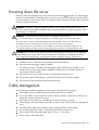
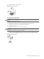
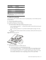
1
HP ProLiant DL140 Generation 3 Server
Maintenance and Service Guide
Part number 413173-005
Fifth edition September 2007
Legal notices
© Copyright 2007 Hewlett-Packard Development Company, L.P.
The information contained herein is subject to change without notice. The only warranties for HP products and services are
set forth in the express warranty statements accompanying such products and services. Nothing herein should be construed
as constituting an additional warranty. HP shall not be liable for technical or editorial errors or omissions contained herein.
Intel and Xeon are US registered trademarks of Intel Corporation. Microsoft and Windows are US registered trademarks of
Microsoft Corporation.
Other products or system names appearing in this document are trademarks or registered trademarks of their respective
owners. Further, the © or TM symbols are not used in the text.
Audience assumptions
This guide is for an experienced service technician. HP assumes you are qualified in the servicing of computer equipment
and trained in recognizing hazards in products with hazardous energy levels and are familiar with weight and stability
precautions for rack installations.
Contents
Customer self repair ............................................................................................................................... 5
Parts only warranty service........................................................................................................................ 5
Illustrated parts catalog ......................................................................................................................... 16
Mechanical components ......................................................................................................................... 16
System components ................................................................................................................................ 20
HP contact information ........................................................................................................................... 25
Before you contact HP ....................................................................................................................... 25
Removal and replacement procedures .................................................................................................... 26
Required tools ....................................................................................................................................... 26
Hardware configuration warnings ............................................................................................................ 26
Server warnings and cautions.................................................................................................................. 26
Symbols on equipment............................................................................................................................ 27
Rack warnings....................................................................................................................................... 28
Electrostatic discharge information ........................................................................................................... 28
Pre-installation procedure ........................................................................................................................ 29
Post-installation procedure ....................................................................................................................... 29
Powering down the server ....................................................................................................................... 30
Cable management................................................................................................................................ 30
Opening the server ................................................................................................................................ 31
Drive bay configuration .......................................................................................................................... 32
System drive cable connections........................................................................................................... 33
Optical media drive .......................................................................................................................... 34
Hard drives ...................................................................................................................................... 36
System board configuration..................................................................................................................... 45
Processor ......................................................................................................................................... 45
Memory........................................................................................................................................... 51
Expansion board .............................................................................................................................. 53
System battery .................................................................................................................................. 57
System fans ........................................................................................................................................... 59
System fan connections ...................................................................................................................... 59
Power supply unit................................................................................................................................... 61
PSU replacement warnings ................................................................................................................. 61
Diagnostic tools ................................................................................................................................... 63
Diagnostic tools overview........................................................................................................................ 63
PhoenixBIOS software ............................................................................................................................ 64
PhoenixBIOS Setup Utility................................................................................................................... 64
Troubleshooting resources ....................................................................................................................... 80
Connectors, switches, and LEDs ............................................................................................................. 81
Connectors and components ................................................................................................................... 81
Front panel....................................................................................................................................... 81
Rear panel ....................................................................................................................................... 82
System board ................................................................................................................................... 83
Front panel board ............................................................................................................................. 85
System switches ..................................................................................................................................... 87
Rear UID button with LED indicator (SW1)............................................................................................ 87
System configuration switch (SW2)...................................................................................................... 88
Contents
3
NMI button (SW4) ............................................................................................................................ 88
Hot-plug HDD peripherals ....................................................................................................................... 89
Hot-plug backplane board.................................................................................................................. 89
Hot-plug cable .................................................................................................................................. 90
Status LED indicators .............................................................................................................................. 90
Front panel LED indicators .................................................................................................................. 91
Hot-plug HDD LED indicators .............................................................................................................. 92
Rear panel LED indicators .................................................................................................................. 94
System specifications ............................................................................................................................ 95
Technical specifications .......................................................................................................................... 95
System unit....................................................................................................................................... 95
Memory........................................................................................................................................... 96
Processor ......................................................................................................................................... 97
IDE CD-ROM drive ............................................................................................................................ 99
Hard drives .................................................................................................................................... 100
System controllers ........................................................................................................................... 102
Power supply unit............................................................................................................................ 103
Physical specifications .......................................................................................................................... 104
Environmental specifications .................................................................................................................. 105
Index ................................................................................................................................................ 106
Contents
4
Customer self repair
HP products are designed with many Customer Self Repair (CSR) parts to minimize repair time and
allow for greater flexibility in performing defective parts replacement. If during the diagnosis period
HP (or HP service providers or service partners) identifies that the repair can be accomplished by the
use of a CSR part, HP will ship that part directly to you for replacement. There are two categories of
CSR parts:
•
Mandatory—Parts for which customer self repair is mandatory. If you request HP to replace
these parts, you will be charged for the travel and labor costs of this service.
•
Optional—Parts for which customer self repair is optional. These parts are also designed for
customer self repair. If, however, you require that HP replace them for you, there may or may not
be additional charges, depending on the type of warranty service designated for your product.
NOTE: Some HP parts are not designed for customer self repair. In order to satisfy the customer
warranty, HP requires that an authorized service provider replace the part. These parts are identified
as "No" in the Illustrated Parts Catalog.
Based on availability and where geography permits, CSR parts will be shipped for next business day
delivery. Same day or four-hour delivery may be offered at an additional charge where geography
permits. If assistance is required, you can call the HP Technical Support Center and a technician will
help you over the telephone. HP specifies in the materials shipped with a replacement CSR part
whether a defective part must be returned to HP. In cases where it is required to return the defective
part to HP, you must ship the defective part back to HP within a defined period of time, normally five
(5) business days. The defective part must be returned with the associated documentation in the
provided shipping material. Failure to return the defective part may result in HP billing you for the
replacement. With a customer self repair, HP will pay all shipping and part return costs and
determine the courier/carrier to be used.
For more information about HP's Customer Self Repair program, contact your local service provider.
For the North American program, refer to the HP website (http://www.hp.com/go/selfrepair).
Parts only warranty service
Your HP Limited Warranty may include a parts only warranty service. Under the terms of parts only
warranty service, HP will provide replacement parts free of charge.
For parts only warranty service, CSR part replacement is mandatory. If you request HP to replace
these parts, you will be charged for the travel and labor costs of this service.
Customer self repair 5
Réparation par le client (CSR)
Les produits HP comportent de nombreuses pièces CSR (Customer Self Repair = réparation par le
client) afin de minimiser les délais de réparation et faciliter le remplacement des pièces défectueuses.
Si pendant la période de diagnostic, HP (ou ses partenaires ou mainteneurs agréés) détermine que la
réparation peut être effectuée à l'aide d'une pièce CSR, HP vous l'envoie directement. Il existe deux
catégories de pièces CSR:
•
Obligatoire - Pièces pour lesquelles la réparation par le client est obligatoire. Si vous
demandez à HP de remplacer ces pièces, les coûts de déplacement et main d'œuvre du service
vous seront facturés.
•
Facultatif - Pièces pour lesquelles la réparation par le client est facultative. Ces pièces sont
également conçues pour permettre au client d'effectuer lui-même la réparation. Toutefois, si vous
demandez à HP de remplacer ces pièces, l'intervention peut ou non vous être facturée, selon le
type de garantie applicable à votre produit.
REMARQUE: Certaines pièces HP ne sont pas conçues pour permettre au client d'effectuer lui-même
la réparation. Pour que la garantie puisse s'appliquer, HP exige que le remplacement de la pièce soit
effectué par un Mainteneur Agréé. Ces pièces sont identifiées par la mention "Non" dans le
Catalogue illustré.
Les pièces CSR sont livrées le jour ouvré suivant, dans la limite des stocks disponibles et selon votre
situation géographique. Si votre situation géographique le permet et que vous demandez une
livraison le jour même ou dans les 4 heures, celle-ci vous sera facturée. Pour bénéficier d'une
assistance téléphonique, appelez le Centre d'assistance technique HP. Dans les documents envoyés
avec la pièce de rechange CSR, HP précise s'il est nécessaire de lui retourner la pièce défectueuse. Si
c'est le cas, vous devez le faire dans le délai indiqué, généralement cinq (5) jours ouvrés. La pièce et
sa documentation doivent être retournées dans l'emballage fourni. Si vous ne retournez pas la pièce
défectueuse, HP se réserve le droit de vous facturer les coûts de remplacement. Dans le cas d'une
pièce CSR, HP supporte l'ensemble des frais d'expédition et de retour, et détermine la société de
courses ou le transporteur à utiliser.
Pour plus d'informations sur le programme CSR de HP, contactez votre Mainteneur Agrée local. Pour
plus d'informations sur ce programme en Amérique du Nord, consultez le site Web HP
(http://www.hp.com/go/selfrepair).
Service de garantie "pièces seules"
Votre garantie limitée HP peut inclure un service de garantie "pièces seules". Dans ce cas, les pièces
de rechange fournies par HP ne sont pas facturées.
Dans le cadre de ce service, la réparation des pièces CSR par le client est obligatoire. Si vous
demandez à HP de remplacer ces pièces, les coûts de déplacement et main d'œuvre du service vous
seront facturés.
Customer self repair 6
Riparazione da parte del cliente
Per abbreviare i tempi di riparazione e garantire una maggiore flessibilità nella sostituzione di parti
difettose, i prodotti HP sono realizzati con numerosi componenti che possono essere riparati
direttamente dal cliente (CSR, Customer Self Repair). Se in fase di diagnostica HP (o un centro di
servizi o di assistenza HP) identifica il guasto come riparabile mediante un ricambio CSR, HP lo
spedirà direttamente al cliente per la sostituzione. Vi sono due categorie di parti CSR:
•
Obbligatorie – Parti che devono essere necessariamente riparate dal cliente. Se il cliente ne
affida la riparazione ad HP, deve sostenere le spese di spedizione e di manodopera per il
servizio.
•
Opzionali – Parti la cui riparazione da parte del cliente è facoltativa. Si tratta comunque di
componenti progettati per questo scopo. Se tuttavia il cliente ne richiede la sostituzione ad HP,
potrebbe dover sostenere spese addizionali a seconda del tipo di garanzia previsto per il
prodotto.
NOTA: alcuni componenti HP non sono progettati per la riparazione da parte del cliente. Per
rispettare la garanzia, HP richiede che queste parti siano sostituite da un centro di assistenza
autorizzato. Tali parti sono identificate da un "No" nel Catalogo illustrato dei componenti.
In base alla disponibilità e alla località geografica, le parti CSR vengono spedite con consegna entro
il giorno lavorativo seguente. La consegna nel giorno stesso o entro quattro ore è offerta con un
supplemento di costo solo in alcune zone. In caso di necessità si può richiedere l'assistenza telefonica
di un addetto del centro di supporto tecnico HP. Nel materiale fornito con una parte di ricambio CSR,
HP specifica se il cliente deve restituire dei componenti. Qualora sia richiesta la resa ad HP del
componente difettoso, lo si deve spedire ad HP entro un determinato periodo di tempo, generalmente
cinque (5) giorni lavorativi. Il componente difettoso deve essere restituito con la documentazione
associata nell'imballo di spedizione fornito. La mancata restituzione del componente può comportare
la fatturazione del ricambio da parte di HP. Nel caso di riparazione da parte del cliente, HP sostiene
tutte le spese di spedizione e resa e sceglie il corriere/vettore da utilizzare.
Per ulteriori informazioni sul programma CSR di HP contattare il centro di assistenza di zona. Per il
programma in Nord America fare riferimento al sito Web HP (http://www.hp.com/go/selfrepair).
Servizio di garanzia per i soli componenti
La garanzia limitata HP può includere un servizio di garanzia per i soli componenti. Nei termini di
garanzia del servizio per i soli componenti, HP fornirà gratuitamente le parti di ricambio.
Per il servizio di garanzia per i soli componenti è obbligatoria la formula CSR che prevede la
riparazione da parte del cliente. Se il cliente invece richiede la sostituzione ad HP, dovrà sostenere le
spese di spedizione e di manodopera per il servizio.
Customer self repair 7
Customer Self Repair
HP Produkte enthalten viele CSR-Teile (Customer Self Repair), um Reparaturzeiten zu minimieren und
höhere Flexibilität beim Austausch defekter Bauteile zu ermöglichen. Wenn HP (oder ein HP
Servicepartner) bei der Diagnose feststellt, dass das Produkt mithilfe eines CSR-Teils repariert werden
kann, sendet Ihnen HP dieses Bauteil zum Austausch direkt zu. CSR-Teile werden in zwei Kategorien
unterteilt:
•
Zwingend – Teile, für die das Customer Self Repair-Verfahren zwingend vorgegeben ist.
Wenn Sie den Austausch dieser Teile von HP vornehmen lassen, werden Ihnen die Anfahrt- und
Arbeitskosten für diesen Service berechnet.
•
Optional – Teile, für die das Customer Self Repair-Verfahren optional ist. Diese Teile sind auch
für Customer Self Repair ausgelegt. Wenn Sie jedoch den Austausch dieser Teile von HP
vornehmen lassen möchten, können bei diesem Service je nach den für Ihr Produkt vorgesehenen
Garantiebedingungen zusätzliche Kosten anfallen.
HINWEIS: Einige Teile sind nicht für Customer Self Repair ausgelegt. Um den Garantieanspruch des
Kunden zu erfüllen, muss das Teil von einem HP Servicepartner ersetzt werden. Im illustrierten
Teilekatalog sind diese Teile mit „No“ bzw. „Nein“ gekennzeichnet.
CSR-Teile werden abhängig von der Verfügbarkeit und vom Lieferziel am folgenden Geschäftstag
geliefert. Für bestimmte Standorte ist eine Lieferung am selben Tag oder innerhalb von vier Stunden
gegen einen Aufpreis verfügbar. Wenn Sie Hilfe benötigen, können Sie das HP technische Support
Center anrufen und sich von einem Mitarbeiter per Telefon helfen lassen. Den Materialien, die mit
einem CSR-Ersatzteil geliefert werden, können Sie entnehmen, ob das defekte Teil an HP
zurückgeschickt werden muss. Wenn es erforderlich ist, das defekte Teil an HP zurückzuschicken,
müssen Sie dies innerhalb eines vorgegebenen Zeitraums tun, in der Regel innerhalb von fünf (5)
Geschäftstagen. Das defekte Teil muss mit der zugehörigen Dokumentation in der Verpackung
zurückgeschickt werden, die im Lieferumfang enthalten ist. Wenn Sie das defekte Teil nicht
zurückschicken, kann HP Ihnen das Ersatzteil in Rechnung stellen. Im Falle von Customer Self Repair
kommt HP für alle Kosten für die Lieferung und Rücksendung auf und bestimmt den Kurier/Frachtdienst.
Weitere Informationen über das HP Customer Self Repair Programm erhalten Sie von Ihrem
Servicepartner vor Ort. Informationen über das CSR-Programm in Nordamerika finden Sie auf der HP
Website unter (http://www.hp.com/go/selfrepair).
Parts-only Warranty Service (Garantieservice
ausschließlich für Teile)
Ihre HP Garantie umfasst möglicherweise einen Parts-only Warranty Service (Garantieservice
ausschließlich für Teile). Gemäß den Bestimmungen des Parts-only Warranty Service stellt HP
Ersatzteile kostenlos zur Verfügung.
Für den Parts-only Warranty Service ist das CSR-Verfahren zwingend vorgegeben. Wenn Sie den
Austausch dieser Teile von HP vornehmen lassen, werden Ihnen die Anfahrt- und Arbeitskosten für
diesen Service berechnet.
Customer self repair 8
Reparaciones del propio cliente
Los productos de HP incluyen muchos componentes que el propio usuario puede reemplazar
(Customer Self Repair, CSR) para minimizar el tiempo de reparación y ofrecer una mayor flexibilidad
a la hora de realizar sustituciones de componentes defectuosos. Si, durante la fase de diagnóstico,
HP (o los proveedores o socios de servicio de HP) identifica que una reparación puede llevarse a
cabo mediante el uso de un componente CSR, HP le enviará dicho componente directamente para
que realice su sustitución. Los componentes CSR se clasifican en dos categorías:
•
Obligatorio: componentes para los que la reparación por parte del usuario es obligatoria. Si
solicita a HP que realice la sustitución de estos componentes, tendrá que hacerse cargo de los
gastos de desplazamiento y de mano de obra de dicho servicio.
•
Opcional: componentes para los que la reparación por parte del usuario es opcional. Estos
componentes también están diseñados para que puedan ser reparados por el usuario. Sin
embargo, si precisa que HP realice su sustitución, puede o no conllevar costes adicionales,
dependiendo del tipo de servicio de garantía correspondiente al producto.
NOTA: Algunos componentes no están diseñados para que puedan ser reparados por el usuario.
Para que el usuario haga valer su garantía, HP pone como condición que un proveedor de servicios
autorizado realice la sustitución de estos componentes. Dichos componentes se identifican con la
palabra "No" en el catálogo ilustrado de componentes.
Según la disponibilidad y la situación geográfica, los componentes CSR se enviarán para que
lleguen a su destino al siguiente día laborable. Si la situación geográfica lo permite, se puede
solicitar la entrega en el mismo día o en cuatro horas con un coste adicional. Si precisa asistencia
técnica, puede llamar al Centro de asistencia técnica de HP y recibirá ayuda telefónica por parte de
un técnico. Con el envío de materiales para la sustitución de componentes CSR, HP especificará si los
componentes defectuosos deberán devolverse a HP. En aquellos casos en los que sea necesario
devolver algún componente a HP, deberá hacerlo en el periodo de tiempo especificado,
normalmente cinco días laborables. Los componentes defectuosos deberán devolverse con toda la
documentación relacionada y con el embalaje de envío. Si no enviara el componente defectuoso
requerido, HP podrá cobrarle por el de sustitución. En el caso de todas sustituciones que lleve a cabo
el cliente, HP se hará cargo de todos los gastos de envío y devolución de componentes y escogerá la
empresa de transporte que se utilice para dicho servicio.
Para obtener más información acerca del programa de Reparaciones del propio cliente de HP,
póngase en contacto con su proveedor de servicios local. Si está interesado en el programa para
Norteamérica, visite la página web de HP siguiente (http://www.hp.com/go/selfrepair).
Servicio de garantía exclusivo de componentes
La garantía limitada de HP puede que incluya un servicio de garantía exclusivo de componentes.
Según las condiciones de este servicio exclusivo de componentes, HP le facilitará los componentes de
repuesto sin cargo adicional alguno.
Para este servicio de garantía exclusivo de componentes, es obligatoria la sustitución de
componentes por parte del usuario (CSR). Si solicita a HP que realice la sustitución de estos
componentes, tendrá que hacerse cargo de los gastos de desplazamiento y de mano de obra de
dicho servicio.
Customer self repair 9
Customer Self Repair
Veel onderdelen in HP producten zijn door de klant zelf te repareren, waardoor de reparatieduur tot
een minimum beperkt kan blijven en de flexibiliteit in het vervangen van defecte onderdelen groter is.
Deze onderdelen worden CSR-onderdelen (Customer Self Repair) genoemd. Als HP (of een HP
Service Partner) bij de diagnose vaststelt dat de reparatie kan worden uitgevoerd met een CSRonderdeel, verzendt HP dat onderdeel rechtstreeks naar u, zodat u het defecte onderdeel daarmee
kunt vervangen. Er zijn twee categorieën CSR-onderdelen:
•
Verplicht: Onderdelen waarvoor reparatie door de klant verplicht is. Als u HP verzoekt deze
onderdelen voor u te vervangen, worden u voor deze service reiskosten en arbeidsloon in
rekening gebracht.
•
Optioneel: Onderdelen waarvoor reparatie door de klant optioneel is. Ook deze onderdelen
zijn ontworpen voor reparatie door de klant. Als u echter HP verzoekt deze onderdelen voor u te
vervangen, kunnen daarvoor extra kosten in rekening worden gebracht, afhankelijk van het type
garantieservice voor het product.
OPMERKING: Sommige HP onderdelen zijn niet ontwikkeld voor reparatie door de klant. In
verband met de garantievoorwaarden moet het onderdeel door een geautoriseerde Service Partner
worden vervangen. Deze onderdelen worden in de geïllustreerde onderdelencatalogus aangemerkt
met "Nee".
Afhankelijk van de leverbaarheid en de locatie worden CSR-onderdelen verzonden voor levering op
de eerstvolgende werkdag. Levering op dezelfde dag of binnen vier uur kan tegen meerkosten
worden aangeboden, indien dit mogelijk is gezien de locatie. Indien assistentie gewenst is, belt u een
HP Service Partner om via de telefoon technische ondersteuning te ontvangen. HP vermeldt in de
documentatie bij het vervangende CSR-onderdeel of het defecte onderdeel aan HP moet worden
geretourneerd. Als het defecte onderdeel aan HP moet worden teruggezonden, moet u het defecte
onderdeel binnen een bepaalde periode, gewoonlijk vijf (5) werkdagen, retourneren aan HP. Het
defecte onderdeel moet met de bijbehorende documentatie worden geretourneerd in het
meegeleverde verpakkingsmateriaal. Als u het defecte onderdeel niet terugzendt, kan HP u voor het
vervangende onderdeel kosten in rekening brengen. Bij reparatie door de klant betaalt HP alle
verzendkosten voor het vervangende en geretourneerde onderdeel en kiest HP zelf welke
koerier/transportonderneming hiervoor wordt gebruikt.
Neem contact op met een Service Partner voor meer informatie over het Customer Self Repair
programma van HP. Informatie over Service Partners vindt u op de HP website
(http://www.hp.nl/services/servicepartners).
Garantieservice "Parts Only"
Het is mogelijk dat de HP garantie alleen de garantieservice "Parts Only" omvat. Volgens de
bepalingen van de Parts Only garantieservice zal HP kosteloos vervangende onderdelen ter
beschikking stellen.
Voor de Parts Only garantieservice is vervanging door CSR-onderdelen verplicht. Als u HP verzoekt
deze onderdelen voor u te vervangen, worden u voor deze service reiskosten en arbeidsloon in
rekening gebracht.
Customer self repair 10
Reparo feito pelo cliente
Os produtos da HP são projetados com muitas peças para reparo feito pelo cliente (CSR) de modo a
minimizar o tempo de reparo e permitir maior flexibilidade na substituição de peças com defeito. Se,
durante o período de diagnóstico, a HP (ou fornecedores/parceiros de serviço da HP) concluir que o
reparo pode ser efetuado pelo uso de uma peça CSR, a peça de reposição será enviada diretamente
ao cliente. Existem duas categorias de peças CSR:
•
Obrigatória – Peças cujo reparo feito pelo cliente é obrigatório. Se desejar que a HP substitua
essas peças, serão cobradas as despesas de transporte e mão-de-obra do serviço.
•
Opcional – Peças cujo reparo feito pelo cliente é opcional. Essas peças também são
projetadas para o reparo feito pelo cliente. No entanto, se desejar que a HP as substitua, pode
haver ou não a cobrança de taxa adicional, dependendo do tipo de serviço de garantia
destinado ao produto.
OBSERVAÇÃO: Algumas peças da HP não são projetadas para o reparo feito pelo cliente. A fim
de cumprir a garantia do cliente, a HP exige que um técnico autorizado substitua a peça. Essas
peças estão identificadas com a marca "No" (Não), no catálogo de peças ilustrado.
Conforme a disponibilidade e o local geográfico, as peças CSR serão enviadas no primeiro dia útil
após o pedido. Onde as condições geográficas permitirem, a entrega no mesmo dia ou em quatro
horas pode ser feita mediante uma taxa adicional. Se precisar de auxílio, entre em contato com o
Centro de suporte técnico da HP para que um técnico o ajude por telefone. A HP especifica nos
materiais fornecidos com a peça CSR de reposição se a peça com defeito deve ser devolvida à HP.
Nos casos em que isso for necessário, é preciso enviar a peça com defeito à HP dentro do período
determinado, normalmente cinco (5) dias úteis. A peça com defeito deve ser enviada com a
documentação correspondente no material de transporte fornecido. Caso não o faça, a HP poderá
cobrar a reposição. Para as peças de reparo feito pelo cliente, a HP paga todas as despesas de
transporte e de devolução da peça e determina a transportadora/serviço postal a ser utilizado.
Para obter mais informações sobre o programa de reparo feito pelo cliente da HP, entre em contato
com o fornecedor de serviços local. Para o programa norte-americano, visite o site da HP
(http://www.hp.com/go/selfrepair).
Serviço de garantia apenas para peças
A garantia limitada da HP pode incluir um serviço de garantia apenas para peças. Segundo os
termos do serviço de garantia apenas para peças, a HP fornece as peças de reposição sem cobrar
nenhuma taxa.
No caso desse serviço, a substituição de peças CSR é obrigatória. Se desejar que a HP substitua
essas peças, serão cobradas as despesas de transporte e mão-de-obra do serviço.
Customer self repair 11
Customer self repair 12
Customer self repair 13
Customer self repair 14
Customer self repair 15
Illustrated parts catalog
Mechanical components
Table 1 Mechanical components spare parts list
Item
Description
Spare part number
Customer self
Repair
1
Top cover
416353-001
Mandatory
2
PCI riser board assembly
416345-001
Mandatory
3
Air duct
390981-001
Mandatory
4
Front bezel
416352-001
Mandatory
5
Processor air baffle*
394556-001
Mandatory
6
Processor mounting plate*
390396-001
Mandatory
* not shown
Mandatory—Parts for which customer self repair is mandatory. If you request HP to replace these
parts, you will be charged for the travel and labor costs of this service.
1
Optional—Parts for which customer self repair is optional. These parts are also designed for
customer self repair. If, however, you require that HP replace them for you, there may or may not be
additional charges, depending on the type of warranty service designated for your product.
2
No—Some HP parts are not designed for customer self repair. In order to satisfy the customer
warranty, HP requires that an authorized service provider replace the part. These parts are identified
as "No" in the Illustrated Parts Catalog.
3
Illustrated parts catalog 16
Mandatory: Obligatoire—Pièces pour lesquelles la réparation par le client est obligatoire. Si vous
demandez à HP de remplacer ces pièces, les coûts de déplacement et main d'œuvre du service vous
seront facturés.
1
Optional: Facultatif—Pièces pour lesquelles la réparation par le client est facultative. Ces pièces sont
également conçues pour permettre au client d'effectuer lui-même la réparation. Toutefois, si vous
demandez à HP de remplacer ces pièces, l'intervention peut ou non vous être facturée, selon le type
de garantie applicable à votre produit.
2
No: Non—Certaines pièces HP ne sont pas conçues pour permettre au client d'effectuer lui-même la
réparation. Pour que la garantie puisse s'appliquer, HP exige que le remplacement de la pièce soit
effectué par un Mainteneur Agréé. Ces pièces sont identifiées par la mention “Non” dans le
Catalogue illustré.
3
Mandatory: Obbligatorie—Parti che devono essere necessariamente riparate dal cliente. Se il cliente
ne affida la riparazione ad HP, deve sostenere le spese di spedizione e di manodopera per il
servizio.
1
Optional: Opzionali—Parti la cui riparazione da parte del cliente è facoltativa. Si tratta comunque
di componenti progettati per questo scopo. Se tuttavia il cliente ne richiede la sostituzione ad HP,
potrebbe dover sostenere spese addizionali a seconda del tipo di garanzia previsto per il prodotto.
2
No: Non CSR—Alcuni componenti HP non sono progettati per la riparazione da parte del cliente.
Per rispettare la garanzia, HP richiede che queste parti siano sostituite da un centro di assistenza
autorizzato. Tali parti sono identificate da un “No” nel Catalogo illustrato dei componenti.
3
Mandatory: Zwingend—Teile, die im Rahmen des Customer Self Repair Programms ersetzt werden
müssen. Wenn Sie diese Teile von HP ersetzen lassen, werden Ihnen die Versand- und Arbeitskosten
für diesen Service berechnet.
1
Optional: Optional—Teile, für die das Customer Self Repair-Verfahren optional ist. Diese Teile sind
auch für Customer Self Repair ausgelegt. Wenn Sie jedoch den Austausch dieser Teile von HP
vornehmen lassen möchten, können bei diesem Service je nach den für Ihr Produkt vorgesehenen
Garantiebedingungen zusätzliche Kosten anfallen.
2
No: Kein—Einige Teile sind nicht für Customer Self Repair ausgelegt. Um den Garantieanspruch des
Kunden zu erfüllen, muss das Teil von einem HP Servicepartner ersetzt werden. Im illustrierten
Teilekatalog sind diese Teile mit „No“ bzw. „Nein“ gekennzeichnet.
3
Mandatory: Obligatorio—componentes para los que la reparación por parte del usuario es
obligatoria. Si solicita a HP que realice la sustitución de estos componentes, tendrá que hacerse
cargo de los gastos de desplazamiento y de mano de obra de dicho servicio.
1
Optional: Opcional— componentes para los que la reparación por parte del usuario es opcional.
Estos componentes también están diseñados para que puedan ser reparados por el usuario. Sin
embargo, si precisa que HP realice su sustitución, puede o no conllevar costes adicionales,
dependiendo del tipo de servicio de garantía correspondiente al producto.
2
No: No—Algunos componentes no están diseñados para que puedan ser reparados por el usuario.
Para que el usuario haga valer su garantía, HP pone como condición que un proveedor de servicios
autorizado realice la sustitución de estos componentes. Dichos componentes se identifican con la
palabra “No” en el catálogo ilustrado de componentes.
3
Illustrated parts catalog 17
Mandatory: Verplicht—Onderdelen waarvoor Customer Self Repair verplicht is. Als u HP verzoekt
deze onderdelen te vervangen, komen de reiskosten en het arbeidsloon voor uw rekening.
1
Optional: Optioneel—Onderdelen waarvoor reparatie door de klant optioneel is. Ook deze
onderdelen zijn ontworpen voor reparatie door de klant. Als u echter HP verzoekt deze onderdelen
voor u te vervangen, kunnen daarvoor extra kosten in rekening worden gebracht, afhankelijk van het
type garantieservice voor het product.
2
No: Nee—Sommige HP onderdelen zijn niet ontwikkeld voor reparatie door de klant. In verband
met de garantievoorwaarden moet het onderdeel door een geautoriseerde Service Partner worden
vervangen. Deze onderdelen worden in de geïllustreerde onderdelencatalogus aangemerkt met
"Nee".
3
Mandatory: Obrigatória—Peças cujo reparo feito pelo cliente é obrigatório. Se desejar que a HP
substitua essas peças, serão cobradas as despesas de transporte e mão-de-obra do serviço.
1
Optional: Opcional—Peças cujo reparo feito pelo cliente é opcional. Essas peças também são
projetadas para o reparo feito pelo cliente. No entanto, se desejar que a HP as substitua, pode
haver ou não a cobrança de taxa adicional, dependendo do tipo de serviço de garantia destinado
ao produto.
2
No: Nenhuma—Algumas peças da HP não são projetadas para o reparo feito pelo cliente. A fim de
cumprir a garantia do cliente, a HP exige que um técnico autorizado substitua a peça. Essas peças
estão identificadas com a marca “No” (Não), no catálogo de peças ilustrado.
3
Illustrated parts catalog 18
Illustrated parts catalog 19
System components
Table 2 System components spare parts list
Item
Description
Spare part
number
Customer self
repair
1
System fan module
416350-001
Mandatory
2
Processor heat sink
416348-001
Optional
3
Processor
Optional
Quad-Core Intel Xeon Processors
a) E5310 (1.60 GHz, 1066 MHz FSB, 80W)
453310-001
b) E5320 (1.86 GHz, 1066 MHz FSB, 80W)*
453309-001
c) E5335 (2.0 GHz, 1333 MHz FSB, 80W)*
453307-001
d) E5345 (2.33 GHz, 1333 MHz FSB, 80W)*
453308-001
e) L5320 LV (1.86 GHz, 1066 MHz FSB, 50W)*
453311-001
f) L5335 (2.0 GHz, 1333 MHz FSB, 50W)*
452664-001
g) X5355 (2.66 GHz, 1333 MHz FSB, 120W)*
453306-001
h) X5365 (3.0 GHz, 1333 MHz FSB, 120W)*
436520-001
Dual-Core Intel Xeon Processors
a) 5050 (3.00 GHz, 667 MHz FSB, 95W)*
409423-001
b) 5060 (3.20 GHz, 1066 MHz FSB, 130W)*
409424-001
c) 5080 (3.73 GHz, 1066 MHz FSB, 130W)*
412955-001
d) 5110 (1.60 GHz, 1066 MHz FSB, 65W)*
458693-001
e) 5130 (2.0 GHz, 1333 MHz FSB, 65W)*
458692-001
f) 5140 (2.33 GHz, 1333 MHz FSB, 65W)*
458691-001
g) 5148 LV (2.33 GHz, 1333 MHz FSB, 40W)*
458690-001
Illustrated parts catalog 20
Table 2 System components spare parts list
Item
4
Description
Spare part
number
h) 5150 (2.66 GHz, 1333 MHz FSB, 65W)*
458689-001
i) 5160 (3.0 GHz, 1333 MHz FSB, 80W)*
458688-001
Customer self
repair
Mandatory
Memory
a) 512 MB DDR2-667MHz FBD
416470-001
b) 1 GB DDR2-667MHz FBD*
416471-001
c) 2 GB DDR2-667MHz FBD*
416472-001
d) 4 GB DDR2-667MHz FBD*
416473-001
System boards
5
System board
440633-001
Optional
6
Front panel board
411749-001
Mandatory
7
Hot-plug backplane board
416347-001
Mandatory
8
Hot-plug SATA/SAS PCI-X controller board
366493-001
Mandatory
9
Low-profile PCI-X riser board
408293-001
Mandatory
10
PCI Express riser boards
Mandatory
a) Standard height/full-length PCI Express x16 riser board
416346-001
b) Low-profile PCI Express x8 riser board
413435-001
Mass storage devices
11
12
13
Optical media drive
Mandatory
a) IDE CD-ROM drive (24X)
390535-001
b) DVD-ROM drive (8X)*
383981-005
c) DVD/CD-RW combo drive*
398760-001
d) DVD-RW drive*
399403-001
Non-hot-plug SATA hard drive
Mandatory
a) 80 GB
399967-001
b) 160 GB*
399968-001
c) 250 GB*
399969-001
d) 500 GB*
404654-001
Hot-plug hard drive
Mandatory
a) 80 GB SATA hard drive
397551-001
b) 160 GB SATA hard drive*
397552-001
c) 250 GB SATA hard drive*
397553-001
d) 500 GB SATA hard drive*
395501-001
e) 750 GB SATA hard drive*
432401-001
f) 36 GB SAS hard drive*
376593-001
g) 72 GB SAS hard drive*
376594-001
h) 146 GB SAS hard drive*
376595-001
i) 300 GB SAS hard drive*
432146-001
Illustrated parts catalog 21
Table 2 System components spare parts list
Item
Description
Spare part
number
Customer self
repair
Signal cable kits*
14
IDE data cable assembly
390494-001
Mandatory
15
Non-hot-plug SATA data cable
416351-001
Mandatory
16
Hot-plug cable
385840-001
Mandatory
Power
17
650W power supply unit
416349-001
Mandatory
18
3V 200-mAh internal lithium battery for system board
153099-001
Mandatory
Miscellaneous*
19
Front USB port cable*
408287-001
Mandatory
20
Front panel board cable*
390493-001
Mandatory
21
Hardware/plastic kit*
416354-001
Mandatory
22
Hardware mounting kit*
360104-001
Mandatory
* not shown
Mandatory—Parts for which customer self repair is mandatory. If you request HP to replace these
parts, you will be charged for the travel and labor costs of this service.
1
Optional—Parts for which customer self repair is optional. These parts are also designed for
customer self repair. If, however, you require that HP replace them for you, there may or may not be
additional charges, depending on the type of warranty service designated for your product.
2
No—Some HP parts are not designed for customer self repair. In order to satisfy the customer
warranty, HP requires that an authorized service provider replace the part. These parts are identified
as "No" in the Illustrated Parts Catalog.
3
Mandatory: Obligatoire—Pièces pour lesquelles la réparation par le client est obligatoire. Si vous
demandez à HP de remplacer ces pièces, les coûts de déplacement et main d'œuvre du service vous
seront facturés.
1
Optional: Facultatif—Pièces pour lesquelles la réparation par le client est facultative. Ces pièces sont
également conçues pour permettre au client d'effectuer lui-même la réparation. Toutefois, si vous
demandez à HP de remplacer ces pièces, l'intervention peut ou non vous être facturée, selon le type
de garantie applicable à votre produit.
2
No: Non—Certaines pièces HP ne sont pas conçues pour permettre au client d'effectuer lui-même la
réparation. Pour que la garantie puisse s'appliquer, HP exige que le remplacement de la pièce soit
effectué par un Mainteneur Agréé. Ces pièces sont identifiées par la mention “Non” dans le
Catalogue illustré.
3
Mandatory: Obbligatorie—Parti che devono essere necessariamente riparate dal cliente. Se il cliente
ne affida la riparazione ad HP, deve sostenere le spese di spedizione e di manodopera per il
servizio.
1
Illustrated parts catalog 22
Optional: Opzionali—Parti la cui riparazione da parte del cliente è facoltativa. Si tratta comunque
di componenti progettati per questo scopo. Se tuttavia il cliente ne richiede la sostituzione ad HP,
potrebbe dover sostenere spese addizionali a seconda del tipo di garanzia previsto per il prodotto.
2
No: Non CSR—Alcuni componenti HP non sono progettati per la riparazione da parte del cliente.
Per rispettare la garanzia, HP richiede che queste parti siano sostituite da un centro di assistenza
autorizzato. Tali parti sono identificate da un “No” nel Catalogo illustrato dei componenti.
3
Mandatory: Zwingend—Teile, die im Rahmen des Customer Self Repair Programms ersetzt werden
müssen. Wenn Sie diese Teile von HP ersetzen lassen, werden Ihnen die Versand- und Arbeitskosten
für diesen Service berechnet.
1
Optional: Optional—Teile, für die das Customer Self Repair-Verfahren optional ist. Diese Teile sind
auch für Customer Self Repair ausgelegt. Wenn Sie jedoch den Austausch dieser Teile von HP
vornehmen lassen möchten, können bei diesem Service je nach den für Ihr Produkt vorgesehenen
Garantiebedingungen zusätzliche Kosten anfallen.
2
No: Kein—Einige Teile sind nicht für Customer Self Repair ausgelegt. Um den Garantieanspruch des
Kunden zu erfüllen, muss das Teil von einem HP Servicepartner ersetzt werden. Im illustrierten
Teilekatalog sind diese Teile mit „No“ bzw. „Nein“ gekennzeichnet.
3
Mandatory: Obligatorio—componentes para los que la reparación por parte del usuario es
obligatoria. Si solicita a HP que realice la sustitución de estos componentes, tendrá que hacerse
cargo de los gastos de desplazamiento y de mano de obra de dicho servicio.
1
Optional: Opcional— componentes para los que la reparación por parte del usuario es opcional.
Estos componentes también están diseñados para que puedan ser reparados por el usuario. Sin
embargo, si precisa que HP realice su sustitución, puede o no conllevar costes adicionales,
dependiendo del tipo de servicio de garantía correspondiente al producto.
2
No: No—Algunos componentes no están diseñados para que puedan ser reparados por el usuario.
Para que el usuario haga valer su garantía, HP pone como condición que un proveedor de servicios
autorizado realice la sustitución de estos componentes. Dichos componentes se identifican con la
palabra “No” en el catálogo ilustrado de componentes.
3
Mandatory: Verplicht—Onderdelen waarvoor Customer Self Repair verplicht is. Als u HP verzoekt
deze onderdelen te vervangen, komen de reiskosten en het arbeidsloon voor uw rekening.
1
Optional: Optioneel—Onderdelen waarvoor reparatie door de klant optioneel is. Ook deze
onderdelen zijn ontworpen voor reparatie door de klant. Als u echter HP verzoekt deze onderdelen
voor u te vervangen, kunnen daarvoor extra kosten in rekening worden gebracht, afhankelijk van het
type garantieservice voor het product.
2
No: Nee—Sommige HP onderdelen zijn niet ontwikkeld voor reparatie door de klant. In verband
met de garantievoorwaarden moet het onderdeel door een geautoriseerde Service Partner worden
vervangen. Deze onderdelen worden in de geïllustreerde onderdelencatalogus aangemerkt met
"Nee".
3
Mandatory: Obrigatória—Peças cujo reparo feito pelo cliente é obrigatório. Se desejar que a HP
substitua essas peças, serão cobradas as despesas de transporte e mão-de-obra do serviço.
1
Illustrated parts catalog 23
Optional: Opcional—Peças cujo reparo feito pelo cliente é opcional. Essas peças também são
projetadas para o reparo feito pelo cliente. No entanto, se desejar que a HP as substitua, pode
haver ou não a cobrança de taxa adicional, dependendo do tipo de serviço de garantia destinado
ao produto.
2
No: Nenhuma—Algumas peças da HP não são projetadas para o reparo feito pelo cliente. A fim de
cumprir a garantia do cliente, a HP exige que um técnico autorizado substitua a peça. Essas peças
estão identificadas com a marca “No” (Não), no catálogo de peças ilustrado.
3
Illustrated parts catalog 24
HP contact information
For the name of the nearest HP authorized reseller:
•
•
•
In the United States, call 1-800-345-1518.
In Canada, call 1-800-263-5868.
In other locations, refer to the HP website at www.hp.com.
For HP technical support:
•
In North America:
○ Call 1-800-HP-INVENT (1-800-474-6836). This service is available 24 hours a day, 7 days
a week. For continuous quality improvement, calls may be recorded or monitored.
○ If you have purchased a Care Pack (service upgrade), call 1-800-633-3600. For more
information about Care Packs, refer to the HP website at www.hp.com.
•
Outside North America, call the nearest HP Technical Support Phone Center. For telephone
numbers for worldwide Technical Support Centers, refer to the HP website at www.hp.com.
Before you contact HP
Be sure to have the following information available before you call HP:
•
•
•
•
•
•
•
Technical support registration number (if applicable)
Product serial number
Product model name and number
Applicable error messages
Add-on boards or hardware
Third-party hardware or software
Operating system type and revision level
Illustrated parts catalog 25
Removal and replacement procedures
Required tools
In performing any hardware configuration procedure you may need the following tools:
•
•
T-15 Torx screwdriver
Flat-blade screwdriver
The following references and software tools may also be used:
•
•
•
HP ProLiant DL140 Generation 3 Server Support CD
IPMI Event Log
Diagnostics software
NOTE: The figures used in this guide to illustrate procedural steps are labeled numerically (i.e., 1,
2…). When these figures are used in substep items, the alphabetically labeled instructions
correspond to the numbered labels on the related figure (i.e., Label 1 corresponds to step a, label 2
corresponds to step b, etc.).
Hardware configuration warnings
Read the following sections before performing any servicing or troubleshooting procedure.
WARNING: Only authorized technicians trained by HP should attempt to repair this equipment.
Because of the complexity of the individual boards and subassemblies, no one should attempt to
make repairs at the component level or to make modifications to any printed wiring board.
Improper repairs can create a safety hazard.
CAUTION: Whenever installing hardware or performing maintenance procedures requiring access
to internal components, it is recommended that all server data be backed up to avoid loss.
IMPORTANT: Review the specifications of a new component before installing it to make sure it is
compatible with the server. When you integrate new components into the system, record its model
and serial number, and any other pertinent information for future reference. After completing any
removal or replacement procedure, run the diagnostics program to verify that all components
operate properly.
Server warnings and cautions
Before installing a server, be sure that you understand the following warnings and cautions.
WARNING: To reduce the risk of personal injury from hot surfaces, allow the drives and the internal
system components to cool before touching them.
Removal and replacement procedures
26
CAUTION: The server must always be operated with the system top cover on. Proper cooling is not
achieved when the system covers are removed.
CAUTION: Whenever installing hardware or performing maintenance procedures requiring access
to internal components, it is recommended that all server data be backed up to avoid loss.
IMPORTANT: Before removing any serviceable parts, determine whether the part is hot-plug or nonhot-plug. If the device is non-hot-plug, you must power down the server. Non-hot-plug devices in the
server include the processor, all boards, memory modules, fans, expansion boards, and all system
drives.
IMPORTANT: Review the specifications of a new component before installing it to make sure it is
compatible with the server. When you integrate new components into the system, record its model
and serial number, and any other pertinent information for future reference. After completing any
removal or replacement procedure, run the diagnostics program to verify that all components
operate properly.
Symbols on equipment
The following symbols may be placed on equipment to indicate the presence of potentially hazardous
conditions.
This symbol indicates the presence of hazardous energy circuits or electric shock
hazards. Refer all servicing to qualified personnel.
WARNING: To reduce the risk of injury from electric shock hazards, do not open this
enclosure. Refer all maintenance, upgrades, and servicing to qualified personnel.
This symbol indicates the presence of electric shock hazards. The area contains no
user or field serviceable parts. Do not open for any reason.
WARNING: To reduce the risk of injury from electric shock hazards, do not open this
enclosure.
This symbol on an RJ-45 receptacle indicates a network interface connection.
WARNING: To reduce the risk of electric shock, fire, or damage to the equipment, do
not plug telephone or telecommunications connectors into this receptacle.
This symbol indicates the presence of a hot surface or hot component. If this surface is
contacted, the potential for injury exists.
WARNING: To reduce the risk of injury from a hot component, allow the surface to
cool before touching.
weight1_kg
weight1_lb
This symbol indicates that the component exceeds the recommended weight for one
individual to handle safely.
WARNING: To reduce the risk of personal injury or damage to the equipment,
observe local occupational health and safety requirements and guidelines for manual
material handling.
Removal and replacement procedures
27
These symbols, on power supplies or systems, indicate that the equipment is supplied
by multiple sources of power.
WARNING: To reduce the risk of injury from electric shock, remove all power cords
to completely disconnect power from the system.
Rack warnings
WARNING: To reduce the risk of personal injury or damage to equipment, always ensure that the
rack is adequately stabilized before extending a component outside the rack. A rack may become
unstable if more than one component is extended for any reason. Extend only one component at a
time.
WARNING: To reduce the risk of personal injury or damage to the equipment, be sure that:
•
•
•
•
The leveling jacks are extended to the floor.
The full weight of the rack rests on the leveling jacks.
The stabilizers are attached to the rack, if it is a single rack installation.
The racks are coupled together in multiple rack installations.
WARNING: When installing the server in a Telco rack, make certain that the rack frame is
adequately secured to the building structure at the top and bottom.
WARNING: To reduce the risk of personal injury or damage to the equipment, at least two people
are needed to safely unload the rack from the pallet. An empty 42U rack weighs 115 kg (253 lb),
is over 2.1 m (7 ft) tall, and may become unstable when being moved on its casters. Do not stand
in front of the rack as it rolls down the ramp from the pallet. Handle the rack from both sides.
CAUTION: This ProLiant server is intended for rack-mount operation. The server bezel is made from
glossy material. For safety purposes, do not place the server in the visual field of users to prevent
any accidents arising from light bouncing off the bezel’s surface.
ACHTUNG: Entsprechend der Bildschirmabeitsplatzverordnung, darf das Gerät nicht im Gesichtsfeld
des Bedieners aufgestellt werden, da das Gehäuse eine glänzende Front aufweist.
Electrostatic discharge information
An electrostatic discharge (ESD) can damage static-sensitive devices or microcircuitry. Proper
packaging and grounding techniques are necessary precautions to prevent damage. To prevent
electrostatic damage, observe the following precautions:
•
•
•
Transport products in static-safe containers such as conductive tubes, bags, or boxes.
•
Keep work area free of nonconductive materials, such as ordinary plastic assembly aids and
foam packing.
•
Make sure that you are always properly grounded (earthed) when touching a static-sensitive
component or assembly.
Keep electrostatic-sensitive parts in their containers until they arrive at static-free stations.
Cover workstations with approved static-dissipating material. Use a wrist strap connected to the
work surface, and properly grounded (earthed) tools and equipment.
Removal and replacement procedures
28
•
•
•
Avoid touching pins, leads, or circuitry.
Always place drives with the Printed Circuit Board (PCB) assembly-side down.
Use conductive field service tools.
Pre-installation procedure
Perform the steps below before you open the server or before you remove or replace any component.
1. Perform data backup.
2. Turn off the server and all the peripherals connected to it.
3. Unplug all cables from the power outlets to avoid exposure to high energy levels that may cause
burns when parts are short circuited by metal objects such as tools or jewelry.
If necessary, label each one to expedite reassembly.
4. Disconnect telecommunication cables to avoid exposure to shock hazard from ringing voltages.
5. Open the server according to the instructions described in the “System covers” section later in
this chapter.
6. Follow the ESD precautions listed previously in this chapter when handling any hardware
component.
IMPORTANT: To streamline the configuration process, read through the entire installation/removal
procedure first and make sure you understand it before you before you begin.
Post-installation procedure
Perform the steps below after installing or removing a server component.
1. Be sure all components are installed according to the described step-by-step instructions.
2. Check to make sure you have not left loose tools or parts inside the server.
3. Reinstall any expansion board(s), peripheral(s), board cover(s), bracket (s) and system cable(s)
that have previously been removed.
CAUTION: Do not operate the server for more than ten minutes with the access panel and disk
drives removed. Otherwise, improper cooling airflow may damage the system components.
4. If you have removed the air duct and/or the PCI riser board bracket, reinstall it.
5. Reinstall the top cover.
6. Connect all external cables and the AC power cord to the system.
7. Press the power button
on the front panel to turn on the server.
Removal and replacement procedures
29
Powering down the server
The server does not completely power down when the power button
is pressed. The button toggles
between On and Standby. The standby position removes power from most electronics and the drives,
but some internal circuitry remains active. To completely remove all power from the system, disconnect
all power cords from the server.
WARNING: Hazardous voltages are present inside the server. Always disconnect AC power from
the server and other associated assemblies while working inside the unit. Serious injury may result if
this warning is not observed.
WARNING: To reduce the risk of electric shock or damage to the equipment:
• Do not disable the power cord grounding plug. The grounding plug is an important safety feature.
• Plug the power cord into a grounded (earthed) electrical outlet that is easily accessible at all times.
• Unplug the power cord from the power supply to disconnect power to the equipment.
• Do not route the power cord where it can be walked on or pinched by items placed against it. Pay
particular attention to the plug, electrical outlet, and the point where the cord extends from the server.
CAUTION: Protect the server from power fluctuations and temporary interruptions with a regulating
uninterruptible power supply (UPS). This device protects the hardware from damage caused by
power surges and voltage spikes, and keeps the system in operation during a power failure.
1. Shut down server as directed by the operating system documentation.
2. Press the power button
to toggle to Standby.
This places the server in standby mode changing the power LED indicator to amber. In this
mode, the main power supply output is disabled. Standby does not completely disable or
remove power from the system.
3. Disconnect the AC power cord from the AC outlet and then from the server.
4. Check that the power LED indicator is turned off and that the fan noise has stopped.
5. Disconnect all external peripheral devices from the server.
Cable management
Always follow good cable management practices when working inside the computer.
•
•
Keep cables away from major heat sources like the heat sink fan assembly.
•
•
Keep cables clear of sliding or moveable parts to prevent cutting or crimping.
•
•
•
•
Some flat ribbon cables come prefolded. Never change the folds on these cables.
Do not jam cables on top of expansion cards or memory modules. Printed circuit cards are not
designed to withstand excessive pressure.
When folding a flat ribbon cable, never fold to a sharp crease. Sharp creases may damage the
wires.
Do not sharply bend any cable. A sharp bend can break the internal wires.
Never bend a SATA data cable tighter than a 30 mm (1.18 in) radius.
Never crease a SATA data cable.
Removal and replacement procedures
30
•
Do not rely on components like the drive cage, power supply, or system cover to push cables
down into the chassis.
Opening the server
The top cover is detachable. Remove this cover before you can remove or replace a server
component.
To remove the top cover:
1. Perform steps 1 through 3 of the pre-installation procedure.
2. Detach the top cover from the chassis.
a. Loosen the captive thumbscrew on the rear panel.
b. Slide the cover approximately 1.25 cm (0.5 in) toward the rear of the unit, and then lift the
cover to detach it from the chassis.
Figure 1 Removing the top cover
3. Place the top cover in a safe place for reinstallation later.
Removal and replacement procedures
31
To reinstall the top cover:
1. Perform steps 1 through 4 of the post-installation procedure.
2. Reinstall the top cover.
a. Align the cover to the chassis and then slide it towards the front panel to position it into
place.
b. Once the cover is attached to the chassis, secure it by tightening the captive thumbscrew on
the rear panel.
Figure 2 Reinstalling the top cover
3. Perform steps 6 and 7 of the post-installation procedure.
Drive bay configuration
The server supports three drive bays—two drive bays for 1-inch hard disk drives and one drive bay
for a slim-type optical media drive.
Go to the HP website at www.hp.com and refer to the options list for this server model for the latest
information on supported hard drives and optical media drives.
Figure 3 System drive bays
Item
Description
1
1-inch hard disk drive bays (two)
2
Optical media device bay
NOTE: The HDD bays support both non-hot-plug and
hot-plug SATA drives, as well as hot-plug SAS drives.
Removal and replacement procedures
32
System drive cable connections
This section highlights the location of the system board connectors for the system drives’ data cables.
IMPORTANT: Observe the cable management guidelines listed on page 30 when routing the drive
cables.
NOTE: The data cable of a SAS hard drive should be connected to the installed SAS controller
board.
Optical media drive cables
Figure 4 Optical media drive cable connections
Item
Description
1
IDE data cable
2
Optical media drive power cable
Hard drive cables
Non-hot-plug SATA hard drive cables
Figure 5 Non-hot-plug SATA HDD cable connections
Item
Description
1
Non-hot-plug SATA drive power cable
2
Non-hot-plug SATA data cable
Removal and replacement procedures
33
Hot-plug SATA/SAS hard drive cables
Figure 6 Hot-plug SATA/SAS HDD cable connections
Item
Description
1
9-pin HDD LED cable connector
2
HDD 2 data cable connector
3
HDD 1 data cable connector
4
15-pin HDD power cable connector
Optical media drive
The optical media device bay supports the installation of a slim-type CD-ROM or DVD-ROM drive.
To install a CD or DVD drive:
1. Perform the pre-installation procedure.
2. Prepare the optical media device bay for installation.
a. Pull up the optical media device bay release lever, and then push the drive carrier partially
out through the front of the chassis.
b. Pull the drive carrier out of the chassis.
c. Remove the screw securing the drive carrier bezel.
d. Detach the drive carrier bezel.
Store the drive carrier bezel (with its screw) for reassembly later.
CAUTION: Do not discard the drive carrier bezel. If the optical drive is removed in the future, this
bezel must be reinstalled in the chassis for proper cooling of the system.
Removal and replacement procedures
34
Figure 7 Preparing the optical media device bay for installation
3. Remove the new optical drive from its protective packaging.
The optical drive option kits include mounting screws for drive installation.
4. Install the new optical drive in its carrier.
a. Align the optical drive in the carrier.
b. Secure the drive with two mounting screws.
Figure 8 Installing the optical media drive in its carrier
5. Install the new optical drive into the chassis.
a. Slide the optical drive assembly into the chassis until the media device bay release lever
snaps into place.
b. Make sure the optical drive cables are routed neatly. Secure them using the pre-installed
cable clips located on the chassis base.
c. Connect the IDE data and power cables to their corresponding connectors on the optical
drive’s backplane board.
Figure 9 Installing the optical drive assembly in the chassis
6. Perform the post-installation procedure.
Removal and replacement procedures
35
Hard drives
Hard drives installed in the server are labeled as Device 1 and Device 2, from left to right, when
viewed from the front of the server.
Figure 10 Hard drive device numbers
Hard drive support
The server’s HDD bays support both non-hot-plug and hot-plug SATA drives, as well as hot-plug SAS
drives. The low-end system comes with a single hard drive. The type and capacity of drives vary
based on the server model. Your ProLiant server currently supports the following drive capacities:
•
•
•
Non-hot-plug SATA drives – 80-, 160-, 250, and 500-GB
Hot-plug SATA drives – 80-, 160-, 250, 500, and 750-GB
Hot-plug SAS drives – 36-, 72-, 146-, and 300-GB
The non-hot-plug SATA drive options do not include a carrier. Use the HDD carriers and mounting
screws included with your server to install these drives.
The hot-plug SATA and SAS drive options come with their own hot-plug HDD carrier. Users can
directly install these drives into the server.
Guidelines for installing hard drives
•
Install only hard drive models specified for your ProLiant server. Installing unsupported hard
drives may damage the system by consuming power and generating heat in excess of the
server’s operating tolerance. This condition may result in a loss of system and/or data integrity.
•
Install non-hot-plug drives in the drive carriers included with the server chassis using four of the
six HDD screws pre-installed in each of the two HDD carriers.
Figure 11 HDD mounting screws
Removal and replacement procedures
36
•
The hot-plug hard drive options come with its own HDD carrier. This carrier has two LED
indicators (drive activity and fault identification) to show the hot-plug drive’s current status.
•
If you removed a hard drive without plans of installing a new one, you must reinstall the
mounting screws to the blank HDD carrier, and then reinstall the carrier in the chassis for proper
cooling of the system.
Removing a hard drive
To remove a non-hot-plug SATA hard drive:
1. Perform the pre-installation procedure.
2. Remove the non-hot-plug SATA hard drive from the chassis.
a. Disconnect the data and power cables from the rear of the hard drive.
b. Loosen the screw that secures the HDD carrier to the chassis.
c. Push the HDD carrier towards the front of the chassis, and then slide it out completely.
Figure 12 Removing the hard drive from the chassis
3. Remove the non-hot-plug SATA hard drive from its carrier.
a. Remove the four mounting screws that secure the hard drive to the carrier.
b. Remove the hard drive from its carrier.
Figure 13 Removing the non-hot-plug SATA hard drive from its carrier
Removal and replacement procedures
37
To remove a hot-plug SATA/SAS hard drive:
1. Make sure that the drive activity and fault identification LED indicators on the HDD carrier are
off.
2. Remove the hot-plug SATA/SAS hard drive from the chassis.
a. Press the hard disk carrier button to release the ejector lever.
b. Use the ejector lever to pull the drive out of the cage.
Make sure to support the drive when pulling it out of the cage.
Figure 14 Removing the hot-plug SATA/SAS hard drive from the chassis
3. Remove the hot-plug SATA/SAS hard drive from its carrier.
a. Remove the four mounting screws that secure the hard drive to the carrier.
b. Remove the hard drive from its carrier.
Figure 15 Removing the hot-plug SATA/SAS hard drive from its carrier
Configuring a non-hot-plug SATA hard drive
To install a non-hot-plug SATA hard drive:
NOTE: If you are switching from a hot-plug SAS hard drive system to a non-hot-plug SATA one, you
first need to remove the hot-plug backplane board, the hot-plug SATA/SAS controller board, and
the hot-plug cable. After that install the non-hot-plug SATA cable.
1. Perform the pre-installation procedure.
2. Select which drive bay you will use to install the new non-hot-plug SATA hard drive.
If the desired drive bay is occupied, remove the currently installed drive following the procedure
described on page 37.
If the desired drive bay is empty, slide the blank HDD carrier from the bay, and then remove four
mounting screws from it. You will use these screws to install the new drive.
Removal and replacement procedures
38
3. Install the new non-hot-plug SATA hard drive in its carrier.
If you are installing the new drive in a previously occupied drive bay, use the HDD carrier and
mounting screws you removed from the old drive.
If you are installing the new drive in an empty drive bay, use the HDD carrier and mounting
screws you removed from that drive bay.
a. Align the new hard drive on the carrier.
b. Secure the hard drive assembly with the four mounting screws.
c. Slide the hard drive assembly into the chassis.
Figure 16 Installing a non-hot-plug SATA hard drive
4. Connect the non-hot-plug SATA drive cables.
a. Connect the SATA data and power cables to their corresponding connectors on the rear of
the new drive.
b. Check that all cables are clear of the hard drive carrier, and then tighten the screw that
secures the hard drive assembly to the chassis.
Figure 17 Connecting the non-hot-plug SATA hard drive cables
5. Perform the post-installation procedure.
6. Set up the SATA configuration.
For detailed procedures, refer to the Server Support CD or to the operating system
documentation.
Removal and replacement procedures
39
Configuring a hot-plug SATA/SAS hard drive
NOTE: The procedures below assume that the user is switching from a non-hot-plug SATA hard drive
system to a hot-plug SATA/SAS one.
The steps listed below give an overview of the hot-plug SATA/ SAS hard drive configuration
procedure.
1. Install the hot-plug backplane board.
2. Install the PCI-X riser board.
3. Install the hot-plug SATA/SAS controller board.
4. Install the hot-plug cable.
5. Install the hot-plug SATA/SAS hard drive.
6. Set up the SATA/SAS configuration.
To install the hot-plug backplane board:
1. Perform the pre-installation procedure.
2. Remove the non-hot-plug HDD carriers and the non-hot-plug SATA data cables from the unit.
3. Rotate the blue T-locks on top of the HDD cage to the unlock position.
Figure 18 Unlocking the HPBB T-locks
4. Install the hot-plug backplane board (HPBB).
a. Position the board, so that the connectors for the drive engagement are inside the drive
cage, and that
b. The hooks on the rear of the drive cage engage with the slots in the board and that the
bottom of the board fits the bent tabs on the chassis base.
c. Rotate the T-locks to the lock position to prevent the board from moving up.
Removal and replacement procedures
40
Figure 19 Installing the hot-plug backplane board
5. Install the PCI-X riser board.
Refer to page 55 for detailed procedure.
6. Install the hot-plug SATA/SAS controller board.
Refer to page 56 for detailed procedure.
7. Install the hot-plug cable.
Proceed to the next section for instructions.
To install the hot-plug cable:
Procedure for the hot-plug cable installation varies depending on which expansion slot you used to
install the hot-plug SATA/SAS controller board—the low-profile slot or the standard height/full-length
slot.
1. If you installed the hot-plug SATA/SAS controller board in the low-profile slot, reinstall the PCI
riser board assembly, and then proceed to the next step.
If you installed the hot-plug SATA/SAS controller board in the standard height slot, proceed to
step 4.
2. Route the hot-plug cable from the low-profile slot to the backplane board.
a. Engage the connector end of the cable to the rear connector of the hot-plug SATA/SAS
controller board.
b. Lay the cable between the PCI Express x16 slot and the Intel MCH chipset.
c. Route the cable between the ATX system board power connector and the PCI retainer
bracket.
d. Position the cable underneath the PSU cables, and then pull it through towards the chassis’
partition wall.
e. Secure the cable using the pre-installed cable clips located on the chassis base.
Removal and replacement procedures
41
Figure 20 Routing the hot-plug cable from the low-profile slot
3. Proceed to step 7 for instructions on how to connect the hot-plug cable to the backplane board.
4. Route the hot-plug cable from the standard height slot to the backplane board by first engaging
the connector end of the cable to the rear connector of the hot-plug SATA/SAS controller board.
Figure 21 Connecting the hot-plug cable to a controller board installed in the standard height slot
5. Reinstall the PCI riser board assembly.
a. Align the assembly with the system board expansion slots, and then press it down to ensure
full connection to the system board.
Make sure the hot-plug cable lays flat in the space between the system board and the power
supply unit.
b. Tighten the two captive thumbscrews to secure the assembly to the chassis.
Removal and replacement procedures
42
Figure 22 Reinstalling the PCI riser board assembly
6. Route the hot-plug cable towards the backplane board.
a. Lay the hot-plug cable in the space between the PCI retainer bracket and the power supply
unit.
b. Position the hot-plug cable underneath the PSU cables, and then pull it through towards the
chassis’ partition wall.
c. Pull the hot-plug cable through the cable management opening of the chassis’ partition wall.
d. Secure the hot-plug cable using the pre-installed cable clips located on the chassis base.
Figure 23 Routing the hot-plug cable from the standard height slot
7. Connect the hot-plug and PSU HDD cables to the backplane board.
a. Connect the HDD LED and data cable connectors of the hot-plug cable to the backplane
board.
b. Connect the PSU HDD power cable to the CN7 connector on the backplane board.
Removal and replacement procedures
43
Figure 24 Connecting the backplane board cables
8. Perform the post-installation procedure.
9. Install the new hot-plug SATA/SAS hard drive to the unit.
Proceed to the next section for instructions.
To install a hot-plug SATA/SAS hard drive:
1. Select which drive bay you will use to install the new hot-plug SATA/SAS hard drive.
If the desired drive bay is occupied, remove the currently installed drive following the procedure
described in page 38.
If the desired drive bay is empty, slide the blank HDD carrier from the bay.
2. Install the new hot-plug SATA/SAS hard drive.
a. Slide the new drive into the selected drive bay.
b. Close the ejector lever to secure the new drive in the chassis.
Removal and replacement procedures
44
Figure 25 Installing a hot-plug SATA/SAS hard drive
3. Set up the SATA/SAS configuration.
Refer to the documentation that came with the hot-plug SATA/SAS controller board for detailed
procedure.
System board configuration
Refer to the following sections for instructions about how to remove or replace the processor, memory
modules, expansion boards, the IPMI card, and the system battery.
Processor
The server’s two LGA771 processor sockets support Dual-Core and Quad-Core Intel Xeon processors.
Figure 26 Processor socket location
Processor installation guidelines
When configuring the processor, observe the following important guidelines:
•
Processor socket 1 (CPU1) must always be populated. If no processor is installed in this socket,
the system will fail to boot and will halt during POST (Power-On Self-Test). This error prevents the
system from functioning properly.
Removal and replacement procedures
45
Figure 27 Processor socket numbers
•
Handle the processor and heat sink with care. Damage to either may prevent the system from
functioning properly.
•
•
The pins beneath the processor are very fragile. Do not bend or damage them.
•
Be sure that the server has the most recent ROM version. Failure to flash the ROM before
installing processors can cause system failure.
•
To prevent the heat sink from tilting to one side during installation/removal procedures, observe
a diagonally opposite pattern (an “X” pattern) when loosening and tightening the four spring
loaded screws.
Always use a new heat sink when replacing the processor. Failure to use new components can
cause damage to the processor.
Processor air baffle
The default system comes with a single processor installed in the CPU1 socket. An air baffle protects
the empty CPU2 socket. If you intend to install a new processor in this socket—creating a
dual-processor configuration—remove the processor air baffle first.
CAUTION: Do not discard the processor air baffle. If the processor in the CPU2 socket is removed in
the future, the air baffle must be reinstalled to maintain proper cooling.
To remove the processor air baffle:
1. Perform the pre-installation procedure.
2. Lift the air duct away from the processor sockets.
Keep it for reinstallation later.
Figure 28 Removing the air duct
Removal and replacement procedures
46
3. Remove the processor air baffle.
a. Remove the screw securing the processor air baffle to the system board.
b. Lift the processor air baffle away from the system board.
Figure 29 Removing the processor air baffle
c. Store the processor air baffle (with its screw) for reassembly later.
Replacing a processor
WARNING: To reduce the risk of personal injury from hot surfaces, allow the heat sink and the
processor to cool before touching them.
CAUTION: To prevent the heat sink from tilting to one side during installation/removal procedures,
observe a diagonally opposite pattern (an “X” pattern) when loosening and tightening the four
spring loaded screws.
The procedure for replacing a current processor consists of five major steps which are as follows:
1. Remove the heat sink.
2. Remove the current processor.
3. Apply thermal grease.
4. Install the new processor.
5. Install the new HSF assembly.
If you intend to install a new processor in an empty socket, perform steps 3 through 5 only.
If you intend to install a new processor in previously empty CPU2 socket, remove the air baffle first,
and then perform steps 3 through 5 only.
Removal and replacement procedures
47
To remove the heat sink:
1. Perform the pre-installation procedure.
2. If necessary, remove any accessory boards or cables that prevent access to the air duct.
3. Lift the air duct away from the processor sockets.
Keep it for reinstallation later.
4. Locate the processor you want to remove.
5. Remove the heat sink.
a. Loosen the four spring-loaded screws a few threads out, observing a diagonally opposite
pattern, and then loosen them completely to release the heat sink from the processor base.
Figure 30 Loosening the heat sink screws
b. Rotate the heat sink a few degrees clockwise and counterclockwise to break the thermal
grease bond loose.
Figure 31 Breaking the thermal grease bond
c. Lift the heat sink away from the system board.
Figure 32 Removing the heat sink
6. Lay the heat sink down in an upright position with the thermal compound side facing upward.
Do not let the thermal compound touch the work surface.
Removal and replacement procedures
48
To remove a processor:
1. Disengage the load lever.
2. Lift up the retention plate to expose the socket body.
3. Grasp the processor by its edges and carefully lift it out of its socket.
Figure 33 Removing the processor
4. Place the processor on a static-dissipating work surface or inside an anti-static bag.
To apply thermal grease:
CAUTION: Never touch the bottom of the processor; any contaminant on this side of the processor
could prevent the mounting pads from making contact with the socket.
CAUTION: Applying too little thermal grease will cause a gap between the contact surfaces. This
means that the heat sink is not even in direct contact with the processor, and therefore its capacity
to draw out heat is greatly reduced. Furthermore, applying too much thermal grease could make it
squish out from the sides and go all over the processor pins or to the system board when the heat
sink is installed. The thermal grease may cause electrical shorts that can damage the system.
1. Use the alcohol pad (included in the new processor spare kit) to clean the contact surfaces on
the heat sink and the new processor. Wipe the contact surfaces several times to make sure that
no particles or dust contaminants are evident. Allow the alcohol to evaporate before continuing.
2. Apply 0.5 gram (0.25 ml) of the thermal grease evenly onto the top of the processor.
To install the new processor:
1. Hold the processor by its edges, and then insert it in the socket.
Make sure that the alignment tabs on the socket fit the two notches located on the edge of the
processor. The pins are keyed in such a way that you cannot install the processor in the wrong
orientation without bending the pins.
2. Close the retention plate.
Removal and replacement procedures
49
3. Engage the load lever back into place.
Figure 34 Installing the processor
To install the new heat sink:
CAUTION: To prevent overheating or a possible system crash, use only a heat sink specified for the
HP ProLiant ML110 Generation 5 Server.
1. Remove and discard the plastic cover protecting the thermal interface material.
Be careful not to touch or scratch the thermal interface material.
2. Install the new heat sink.
a. Align then insert the heat sink on top of the processor.
CAUTION: Do not over tighten the heat sink’s spring loaded screws to prevent them from breaking
off. A maximum torque of 6 in lb is set for the system.
b. Tighten the four spring-loaded screws a few threads in, observing a diagonally opposite
pattern, and then tighten them completely to secure the heat sink to the processor base.
Figure 35 Installing a heat sink
Removal and replacement procedures
50
3. Reinstall the air duct in its place.
Figure 36 Reinstalling the air duct
4. Perform the post-installation procedure.
Memory
The system has eight DIMM slots that support up to 16 GB maximum system memory (2 GB in each of
the eight DIMM slots).
Figure 37 DIMM slots location
The eight DIMM slots are divided into two branches of two channels each. That is:
•
Branch 0
○ Channel 0 – DIMM1 and DIMM 2
○ Channel 1 – DIMM3 and DIMM 4
•
Branch 1
○ Channel 0 – DIMM5 and DIMM 6
○ Channel 1 – DIMM7 and DIMM 8
Memory installation guidelines
•
Use only HP supported fully buffered registered ECC DDR2 667 DRAM modules in 512 MB,
1 GB, 2 GB, or 4 GB capacities.
•
Install identical modules (of the same type, manufacturer, speed, timing, and organization) per
the instructions below.
○ When operating in mirror mode:
− Install the first four modules in the DIMM1, DIMM3, DIMM5, and DIMM7 slots.
− Memory upgrade granularity (i.e. the number of physical modules required for memory
upgrade) is four DIMMs.
Removal and replacement procedures
51
○ When operating in non-mirror mode:
− Install the first pair in the DIMM1 and DIMM3 slots.
− Memory upgrade granularity is two DIMMs. Observe the following channel pair
sequence during installation: DIMM5 - DIMM7, DIMM2 - DIMM4, then DIMM6 - DIMM8.
○ When operating in single DIMM mode, the module should be installed in the DIMM1 slot.
CAUTION: DIMMs can be damaged by improper handling. Always use an anti-static wrist strap and
grounding mat, and discharge static electricity before touching DIMMs.
To remove a memory module:
1. Perform the pre-installation procedure.
2. If necessary, remove any accessory boards or cables that prevent access to the DIMM slots.
3. Locate the memory module you want to remove.
4. Remove the selected memory module.
a. Completely open the holding clips securing the module.
This forces the module up in the slot and makes it easier to remove.
b. Grasp the middle part of the module, and gently pull it upward to remove it from the slot.
Figure 38 Removing a memory module
5. Place the memory module on a static-dissipating work surface or inside an anti-static bag.
6. Perform the post-installation procedure.
To install a memory module:
1. Perform steps 1 and 2 of the previous section.
2. Locate an empty DIMM slot on the system board.
3. If necessary, open the holding clips of the selected DIMM slot.
4. Remove the memory module from its protective packaging, handling it by the edges.
5. Use both hands to hold the module by the edges, and then insert it perpendicularly into the slot
until it locks into place.
The DIMM slots are structured to ensure proper installation. If you insert a memory module but it
does not fit easily into the slot, you may have inserted it incorrectly. Reverse the orientation of the
module and insert it again.
Removal and replacement procedures
52
Figure 39 Installing a memory module
6. Perform the post-installation procedure.
Expansion board
System board PCI expansion slots
There are four PCI expansion slots on the system board.
Figure 40 System board PCI expansion slots
Item
Component code
Description
Function
1
CN4
64-bit/133 MHz * 3.3
V PCI-X slot
Supports a low-profile PCI-X riser board
2
CN5
PCI Express x8 slot
Supports a low-profile PCI Express x8 riser board
3
CN6
64-bit/133 MHz * 3.3
V PCI-X slot
Supports a standard height/full length PCI-X riser
board
5
U32
PCI Express x16 slot
Supports a standard height/full length PCI Express
x16 riser board
NOTE: The 133 MHz speed is only attainable when one PCI-X riser board card is used. If both PCI Express
riser boards are replaced with a PCI-X model, the maximum attainable speed is 100 MHz.
PCI riser board expansion slots
The two PCI Express riser boards attached to the PCI riser board assembly convert the functionality of
the system board expansion slots to a pair of slots positioned at a 90° angle from the system board.
Removal and replacement procedures
53
Figure 41 System default PCI Express riser boards
Item
Description
1
Standard height/full length PCI Express x16
riser board
2
Low-profile PCI Express x8 riser board
NOTE: Users have the option to replace either or both of
the PCI Express riser boards with a PCI-X model using
the PCI-X riser board option kit. This will allow support
for PCI-X expansion boards.
PCI riser board assembly
To remove the PCI riser board assembly:
1. Perform the pre-installation procedure.
2. Disconnect all cables connecting an existing expansion board to the system board.
3. Remove the PCI riser board assembly.
a. Loosen the two captive thumbscrews that secure the assembly to the chassis.
b. Lift the assembly away from the chassis.
Figure 42 Removing the PCI riser board assembly
Removal and replacement procedures
54
To install the PCI-X riser board:
Installing the PCI-X riser board option allows users to install PCI-X compatible expansion boards in the
ProLiant server.
NOTE: For ease of reading, the PCI riser board assembly will simply be referred to as “assembly” in
the succeeding sections. Furthermore, in some figures, the plane section of the PCI riser board
assembly is dimmed out for clarity.
1. Remove the PCI riser board assembly following the procedures described in the previous section.
2. If an expansion board is currently installed on the PCI Express riser board(s), remove it.
3. Remove the PCI Express riser board from the assembly.
a. Remove the three screws securing the riser board to the assembly.
Keep these screws for installing the PCI-X riser board later.
b. Pull the riser board away from the assembly.
Figure 43 Removing the PCI Express riser boards
4. Remove the PCI-X riser board from its protective packaging.
5. Secure the PCI-X riser board to the assembly using two of the three screws you removed in step
3-a.
Figure 44 Installing the PCI-X riser boards
6. Reinstall the PCI riser board assembly.
Refer to the next section for instructions.
Removal and replacement procedures
55
To reinstall the PCI riser board assembly:
1. Align the assembly with the system board expansion slots, and then press it down to ensure full
connection to the system board.
2. Tighten the two captive thumbscrews to secure the assembly to the chassis.
Figure 45 Reinstalling the PCI riser board assembly
3. Perform the post-installation procedure.
Installing a PCI expansion board
Guidelines for installing PCI expansion boards
The system supports up to two expansion boards at a time. Use only HP supported expansion boards
that meet the following specifications:
•
Compliance
○ PCI Express x8 or x16
○ PCI-X (available only when the optional PCI-X riser board is installed)
•
Form factor
○ Low-profile
○ Standard height/full-length
To install a PCI expansion board:
1. Remove the PCI riser board assembly.
2. Identify the slot that is compatible with the expansion board you intend to install.
3. Pull out the slot cover from the selected slot.
Store it for reassembly later.
CAUTION: Do not discard the slot cover. If the expansion board is removed in the future, the slot
cover must be reinstalled to maintain proper cooling.
Removal and replacement procedures
56
Figure 46 Removing the covers of the PCI riser board expansion slots
4. Remove the expansion board from its protective packaging, handling it by the edges.
Some expansion boards can only be installed in one slot but other boards can be configured to
fit in either slot by replacing the default bracket (attached to the board) with a different sized
one. The different sized bracket and instructions on how to attach it to the board is included in
the option kit.
5. Verify that the board’s default bracket is compatible with the configuration of the selected slot.
If it is not compatible, replace the bracket with one that is compatible.
6. Slide the expansion board into the slot, and then firmly press on it to seat it properly.
Figure 47 Installing an expansion board in the PCI riser board expansion slots
7. Connect the necessary cable(s) to the board.
Refer to the documentation that came with the board.
8. Perform the post-installation procedure.
System battery
The HP ProLiant server uses nonvolatile memory that requires a battery to retain system information
when power is removed. The battery, a 3 V 200-mAh internal lithium battery, is located on the system
board (BT1).
Removal and replacement procedures
57
Figure 48 System battery
If the server no longer automatically displays the correct date and time, the system battery that
provides power to the real-time clock may need to be replaced. Under normal use, battery life is 5 to
10 years.
System battery replacement warnings
Observe the following precautions when replacing the system battery:
•
Replace the battery with the same type as the battery recommended by HP. Use of another
battery may present a risk of fire or explosion.
•
A risk of fire and chemical burn exists if the battery is not handled properly. Do not disassemble,
crush, puncture, or short external contacts, or expose the battery to temperatures higher than
60°C (140°F).
•
Do not dispose of used battery in water or fire. Dispose of used batteries according to
manufacturer's instructions.
•
Loss of BIOS settings occurs when the battery is removed. BIOS settings must be reconfigured
whenever the battery is replaced.
To replace the system battery:
1. Remove the PCI riser board assembly.
If necessary, remove any accessory boards or cables that prevent access to the battery socket.
2. Replace the battery.
IMPORTANT: Do not bend the spring latch during battery replacement. For proper operation, the
latch must maintain a position of contact with the battery.
a. Insert a small flat-blade screwdriver or a similar tool between the battery and spring latch to
dislodge the battery from its socket.
b. Lift up the old battery to remove it.
Insert a new battery with the positive polarity (+ side) facing up, and ensure that it is seated
completely.
c. Ensure the spring latch is in place, and that it holds the battery firmly.
Removal and replacement procedures
58
Figure 49 Replacing the system battery
3. Perform the post-installation procedure.
System fans
The server has six system fans located on the chassis’ center wall.
Figure 50 System fans
System fan connections
Figure 51 identifies the system fans by their device number and shows their corresponding cable
connections.
Figure 51 System fan connections
Removal and replacement procedures
59
Device number
Connector
System fan 1 to 4
CN3 to CN6 on the front
panel board
System fan 5
CN9 on the system board
System fan 6
CN8 on the system board
NOTE: System fans 1 to 5 are for the memory modules
and processors, while system fan 6 is for the PCI slots
and system chipsets.
To replace the system fan:
A new system fan can be installed to allow the server to operate properly in case a default system fan
becomes defective.
1. Perform the pre-installation procedure.
2. Locate the system fan you want to replace.
3. Remove the system fan you want to replace.
a. Disconnect the fan cable from its corresponding board connector.
If you are replacing system fan 1 – 4, release the fan cable from the cable clips securing it to
the base of the chassis.
If you are replacing system fan 5 or 6, pull the fan cable through the opening in the center
wall
b. Tug the fan cable upward to release the fan from its bracket, and then pull the fan away from
the bracket.
Figure 52 Removing a system fan
4. Install a new system fan.
a. Insert the new fan into the vacated fan bracket.
b. Connect the fan cable to its corresponding board connector.
If you are replacing system fan 1 – 4, connect the fan cable to the corresponding connector
on the front panel board, and then secure it through its fastener on the base of the chassis.
If you are replacing system fan 5 or 6, route the fan cable through the opening in the center
wall, and then connect them to their corresponding connectors on the system board.
Removal and replacement procedures
60
Figure 53 Installing a system fan
5. Perform the post-installation procedure.
Power supply unit
Located on the rear panel of the server is a single standard autoranging 650-watts PSU with PFC
(power factor correction) function.
Figure 54 Power supply unit
PSU replacement warnings
Observe the following reminders to reduce the risk of personal injury from electric shock hazards
and/or damage to the equipment
•
Installation of the power supply unit should be referred to individuals who are qualified to service
server systems and are trained to deal with equipment capable of generating hazardous energy
levels.
•
DO NOT open the power supply unit. There are no serviceable parts inside it.
To replace the power supply unit:
1. Perform the pre-installation procedure.
2. Remove the default PSU.
Keep the three screws you removed in this step for installing the new PSU later.
a. Disconnect the processor power cable, the system board power cable, and the PSU I2C cable
from the system board (CN15, CN21, and CN18 respectively), and then disconnect the
power cables of all installed drives from the PSU.
b. Remove the PSU mounting screw located between the PSU fans.
c. Remove the two PSU mounting screws located in the rear panel.
Removal and replacement procedures
61
d. Lift the PSU away from the chassis.
Figure 55 Removing the power supply unit
3. Install the new PSU.
CAUTION: Do not over tighten the PSU’s screws to prevent them from breaking off. A maximum
torque of 7 ± 1 is set for the system.
a. Position the new PSU in the PSU section of the chassis.
b. Insert the PSU mounting screw located between the PSU fans.
c. Insert the two PSU mounting screws located in the rear panel.
d. Reconnect the processor power cable, the system board power cable, and the PSU I2C cable
to their respective system board connectors, and then reconnect the power cables of all
installed drives to the PSU.
Figure 56 Installing the power supply unit
4. Perform the post-installation procedure.
Removal and replacement procedures
62
Diagnostic tools
Diagnostic tools overview
The following utilities assist in diagnosing problems, testing hardware, and monitoring and managing
server operations.
Table 3 Diagnostic tools
Tool
What it is
How to run it
User Diagnostics
A tool to assist testing and/or
verifying operation of hardware. If
problems are found, the diagnostics
package isolates failures down to
the replaceable part, whenever
possible.
Diagnostics and utilities must be accessed
when a system configuration error is
detected during POST.
IPMI Event Log
The IPMI Event Log is a log that is
generated by the management
controller (U45) when it detects
significant or critical system
management events. This includes
messages for events such as
‘temperature threshold exceeded’,
‘voltage threshold exceeded’,
‘power fault’, etc.
Check the HP website at www.hp.com for
the most recent version of the HP ProLiant
DL140 Generation 3 User Diagnostics.
To view the IPMI event log:
1 Access the PhoenixBIOS Setup Utility.
2 In the Advanced menu screen, select
the IPMI field, and then press Enter.
3 Select System Event Log, and then
press Enter.
PhoenixBIOS Setup Utility
A hardware configuration program Run BIOS Setup directly by pressing the
used to manage memory, processor, F10 key during POST.
and system settings.
Refer to the “Running the Setup Utility”
section on page 65 for more information.
HP ROMPaq Utility
A utility that upgrades the current
system ROM.
Run this utility from the HP ROMPaq Utility
bootable floppy after powering up the
server.
Check the HP website at www.hp.com for
the most recent version of the HP ProLiant
DL140 Generation 3 ROM.
NOTE: For more information about the diagnostic tools described in this table, and other tools available for
your server, refer to the Servers Troubleshooting Guide located inside the HP ProLiant DL140 Generation 3
Server Support CD. For the most recent version of this guide, go to www.hp.com.
Diagnostic tools 63
PhoenixBIOS software
PhoenixBIOS software is a ROM BIOS-based diagnostic tool that monitors system activity and
performs constant hardware testing to ensure proper system operation. ROM BIOS is a set of
programs permanently stored in an EEPROM chipset (U64) located on the system board. These
programs micro-manage the hardware devices installed on your server.
The PhoenixBIOS software serves three functions:
•
Configure the system settings via the PhoenixBIOS Setup Utility
Using the Setup program, you can install, configure, and optimize the embedded hardware
devices on your system (clock, memory, disk drives, etc.).
•
Initialize hardware at boot via POST routines
At power-on or reset, the software performs POST routines to test system resources and load the
operating system.
•
Perform run-time routines
Using the software, perform basic hardware routines that can be called from DOS and Windows
applications.
PhoenixBIOS Setup Utility
NOTE: NOTE: For ease of reading, PhoenixBIOS Setup Utility will be simply referred to as “Setup”
or “Setup Utility” in this guide. Also, the screenshots used in this guide display various Setup menu
screens with default values identified. These values may not be the same those in your server.
PhoenixBIOS Setup Utility is a hardware configuration program built into your system's Basic
Input/Output System (BIOS). Since most systems are already properly configured and optimized,
there is normally no need to run this utility.
You will need to run this utility under the following conditions:
•
When changing the system configuration including:
○
○
○
○
○
○
○
•
Setting the system time and date
Configuring the hard drives
Specifying the boot device sequence
Installing PCI expansion boards
Upgrading the system BIOS
Configuring the power management modes
Setting up system passwords or making other changes to the security setup
When a configuration error is detected by the system and you are prompted (“Run Setup”
message) to make changes to the BIOS settings.
NOTE: If you repeatedly receive “Run Setup” messages, the battery (BT1) located on the system
board may be defective. In this case, the system cannot retain configuration values in CMOS. Ask a
qualified technician for assistance.
Diagnostic tools 64
The Setup Utility loads the configuration values in a battery-backed nonvolatile memory called CMOS
RAM. This memory area is not part of the system RAM, which allows configuration data to be
retained when power is turned off. The values take effect when the system is booted. POST uses these
values to configure the hardware. If the values and the actual hardware do not agree, POST
generates an error message. You must run this utility to change the BIOS settings from the default or
current configuration.
Running the Setup Utility
1. Turn on the monitor and the server.
2. If the server is already turned on, save your data and exit all open applications, and then restart
the server.
3. During POST, press F10.
If you fail to press F10 before POST is completed, you will need to restart the server.
The first page to be displayed will be the Main menu showing the Setup Utility’s menu bar. Use
the left (←) and right (→) arrow keys to move between selections on the menu bar.
Figure 57 Setup Utility’s Main menu
Diagnostic tools 65
Navigating through the Setup Utility
Use the keys listed in the legend bar on the bottom of the Setup screen to work your way through the
various menu and submenu screens of the Setup Utility.
Table 4 Setup Utility’s navigation keys
Key
Functions
← and →
To move between selections on the menu bar.
↑ and ↓
To move the cursor to the field you want.
The currently selected field will be highlighted. The right side of each menu screen
displays the Item Specific Help panel. This panel displays the help text for the currently
selected field. It updates as you move the cursor to each field.
PgUp and PgDn
To move the cursor to the previous and next page of a multiple page menu.
Home
To move the cursor to the first page of a multiple page menu.
End
To move the cursor to the last page of a multiple page menu.
(+) , (–), and
<Space>
To select a value for the currently selected field (only if it is user-configurable).
Press the (+), (–), or <Space> keys repeatedly to display each possible entry, or the Enter
key to choose from a pop-up menu.
A parameter that is enclosed in square brackets [ ] is user-configurable.
Grayed-out parameters are not user-configurable for one of the following reasons:
• The field value is auto-configured or auto-detected.
• The field value is informational only.
• The field is password-protected.
Enter
To select a field value or display more options for menu marked with ►.
Ctrl+Enter
To expands all device list.
F1 or <Alt+H>
To bring up the General Help window.
The General Help window describes other Setup navigation keys that are not displayed
on the legend bar.
Esc or <Alt+X>
If you press this key:
• On one of the primary menu screens, the Exit menu displays.
• On a submenu screen, the previous screen displays.
• When you are making selections from a pop-up menu, closes the pop-up without
making a selection.
F9
Loads the default system values.
F10
Saves changes and closes the Setup Utility.
Diagnostic tools 66
Setup Utility menus
The Setup Utility provides a menu bar with the menu selections. The menu bar choices are described
in the.
Table 5 Setup Utility's primary menus
Menu
Main
Function
Use this menu to:
•
•
•
•
•
View BIOS information including ROM ID, version number and build date
Set the system time and date.
Configure drive settings for available IDE and SATA devices.
Select which options to run during system boot-up.
View the amount of available conventional and extended memory detected during
boot-up.
• Enter the server asset tag and serial number.
Advanced
Use this menu to:
• Clear all configuration data in a section of memory for ESCD (Extended System
Configuration Data), which stores the configuration settings for non-PnP plug-in devices.
•
•
•
•
•
View the MAC (Media Access Control) address of each of the three LAN ports.
Select a memory branch mode and related setting.
Enable or disable support for PATA and SATA devices.
Select which functions to enable for available USB devices.
Configure the hardware settings for the processors, the onboard Ethernet controllers, the
expansion slots, and the serial port.
• Configure console redirection settings.
• Console redirection allows the system to be displayed on a remote terminal for online
server management.
•
•
•
•
•
View the specification version for the IPMI and BMC firmware
Configure LAN related-settings.
View and/or clear the event log.
View real-time system temperature and voltage data.
Enable or disable the hardware watchdog timer.
CAUTION: Be cautious in setting field values in this menu as any incorrect value may cause
the system to malfunction.
Security
Use this menu to set an administrator password to prevent unauthorized access to the Setup
utility. Refer to the “Administrator password” section on the next page for more information
on using this menu.
Boot
Use this menu to set the preferred drive sequence in which the Setup Utility attempts to boot
the operating system. Options for enabling the PXE function of the LAN ports are also
available.
By default, the server searches for boot devices in the following order:
1 CD-ROM drive (IDE and USB CD-ROM drives)
2 Removable device
3 Hard drive
4 Embedded NIC1*
5 Embedded NIC2*
* Via PXE (Preboot Execution Environment, remote boot)
Diagnostic tools 67
Table 5 Setup Utility's primary menus
Menu
Function
Power
Use this menu to:
• Enable or disable the modem ring power-up function.
• Enable or disable the WOL (Wake-On-LAN) function of the onboard LAN controllers
(U20 and U30)
• Set the mode of operation if a power loss occurs.
Exit
Use this menu to select an exit option to quit from the Setup Utility. Options include:
• Exit Saving Changes - Saves changes made and close the Setup Utility.
Keyboard shortcut: F10
• Exit Discarding Changes - Discards changes made and close the Setup Utility.
• Load Setup Defaults - Loads the factory-default settings for all Setup parameters.
Keyboard shortcut: F9
• Discard Changes - Discards all changes made to the Setup Utility and loads previous
configuration settings.
• Save Changes - Saves all changes made to the Setup Utility.
Administrator password
The Security menu allows users to set an administrator password. When entered, this password will
allow the user to access and change all settings in the Setup Utility.
To set an administrator password:
1. In the Security menu screen, select the Administrator Password Is field then press Enter.
Figure 58 Setting an administrator password
2. Type a new password in the password box.
The password may consist of up to eight alphanumeric characters (A-Z, a-z, 0-9).
3. Retype the password to verify the first entry, and then press Enter.
4. Press F10 to save the password and close the Setup Utility.
After setting the password, Setup automatically sets the selected password field to Enabled.
Diagnostic tools 68
To change the administrator password:
1. In the Security menu screen, select the Administrator Password Is field, and then press Enter.
2. Type the original password in the password box.
3. Type a new password, and then press Enter.
4. Retype the new password to verify the first entry, and then press Enter again.
5. Press F10 to save the password and close the Setup Utility.
To remove the administrator password:
1. In the Security menu screen, select the Administrator Password Is field, and then press Enter.
2. Type the original password, and then press Enter.
3. Press Enter twice without entering anything in the new and confirm password fields.
4. Press F10 to save the changes you made and close the Setup Utility.
5. Setup automatically sets the selected password field to Clear.
To reset the administrator password:
If you forget the administrator password, you need to clear the CMOS and reset the BIOS settings to
regain access the Setup Utility. For instructions, refer to the “Clearing CMOS” section on page 72.
Diagnostic tools 69
Boot-time diagnostic screen
The boot-time diagnostic screen displays basic and important information about the current server
configuration and is necessary for troubleshooting and may be required when asking for technical
support. This information includes:
•
•
•
•
Processor specifications
BIOS version and release date
BMC firmware version
Size of the system and video memory, as well
as the memory size allotted for the cache
RAM and option ROM
•
•
•
•
Serial port base I/O address
Available hard drives and expansion boards
Server asset tag and serial number
MAC address of each of the three LAN ports
It is recommended that you check this screen during the initial system setup and each time you install,
remove, or upgrade accessories.
To view the boot-time diagnostic screen:
You first need to enable the display of the diagnostic screen during bootup. Follow the steps below.
1. In the Main menu screen, select Boot Features.
2. Select the Summary Screen field.
3. Press the plus (+) or minus (-) key to set the field to Enabled.
4. Press F10 to save the changes you made and close the Setup Utility.
5. Reboot the server.
The diagnostic screen is displayed briefly at the end of POST.
6. Press the Pause/Break key to continue displaying the screen until another key is pressed.
7. Press any key to continue with the system bootup.
Diagnostic tools 70
Recording custom Setup values
Keep a record of the custom Setup values you have set up for your system BIOS. If the custom values
ever need restoring (after a CMOS clear, for example), you must run the Setup Utility and enter these
custom settings again. Make sure to update this record whenever you make any change to these
Setup settings or install new hardware.
You can either record the Setup values manually (hard copy) or use a CMOS backup utility.
To manually record the custom Setup values:
1. Access the Setup utility.
2. Go through each menu and submenus page, and press Print Screen to make a hard copy.
For multiple page menus, move to each page and print each screen.
3. If a printer is not available, write down the values on a piece of paper. Make sure to write them
down legibly and accurately.
4. Label and date the Setup values hard copy, and then store it in a safe and accessible place,
preferably with other user documentation for your ProLiant server.
CMOS backup utility
There are third-party utilities that read the CMOS settings and record them to a regular file, which can
then be backed up through normal means, or copied to an external storage media. Some of these
utilities also offer the option of restoring the CMOS settings so you need not re-enter them manually.
These utilities are not always compatible with all versions of CMOS or types of CMOS. In addition,
these utilities are not compatible with all operating system versions. Be sure to use a CMOS backup
utility that is designed for the particular CMOS type and OS version installed in your ProLiant server.
For information on a compatible CMOS backup utility, contact your local HP representative.
Loading system defaults
If your system fails after you make changes in the Setup menus, reboot the server, enter Setup and
load the system default settings to correct the error. These default settings have been selected to
optimize your server’s performance.
To load the system defaults:
1. Reboot the server in a normal manner.
2. During POST, press F10 to access the Setup Utility.
3. Press F9 to load the default values.
4. Press F10 to save the changes you made and close the Setup Utility.
Diagnostic tools 71
Clearing CMOS
You may need to clear the Setup configuration values (CMOS) if the configuration has been
corrupted, or if incorrect settings made in the Setup Utility have caused error messages to be
unreadable. Clearing the CMOS data removes the administrator password.
The clear CMOS switch is switch 2 of the system configuration switch (SW2). Go to page 84 for the
location of this switch.
To clear CMOS:
1. Remove the top cover following the procedures described on page 31.
2. If necessary, remove any expansion boards, assemblies or cables that prevent access to the
system configuration switch.
3. Locate the system configuration switch (SW2) on the system board.
4. Identify SW2-2 of the switch.
By default, SW2-2 is set to the Off position.
5. Set SW2-2 to the On position.
This will clear the CMOS memory.
6. Switch SW2-2 back to its default Off position.
7. Perform the post-installation procedure described on page 29.
8. During POST, press F10 to access the Setup Utility.
9. Press F9 to load the system default values.
10. Press F10 to save the changes you made and close the Setup Utility.
Power-On Self-Test (POST)
Before you can use a server, all devices must be tested and initialized, and the operating system must
be bootstrapped to the memory. This is referred to as Power–On Self–Test or POST. POST is a series
of diagnostic tests that checks firmware and hardware components to ensure that the server is
properly functioning. This diagnostic function automatically runs each time the server is powered on.
These diagnostics, which reside in the BIOS ROM, isolate server-related logic failures and indicate the
board or component that needs to be replaced, as indicated by the error messages. Most server
hardware failures will be accurately isolated during POST. The number of tests displayed depends on
the configuration of the server.
During POST you can press:
•
•
•
•
Esc to skip the HP logo and go to POST boot progress display system summary screen.
F7 to display the Boot menu.
F10 to access the Setup Utility.
F12 to request a network boot (PXE).
POST error indicators
When POST detects a system failure, it either displays a POST error message, or emits a series of
beep codes.
Diagnostic tools 72
POST errors messages
Whenever a non-fatal error occurs during POST, an error message describing the problem appears
onscreen. These text messages are displayed in normal video (white text on black background). It
shows the details of the error. The following is an example of a POST error message:
Error message 1 of 1:
Error code 0103
Keyboard not detected - Keyboard error
In some cases an error message may include recommendations for troubleshooting or require that you
press the Enter key to display recommendations. Follow the instructions on the screen.
Table 6 lists the most common POST error messages with their corresponding troubleshooting
recommendation. It is recommended that you correct the error before proceeding, even if the server
appears to boot successfully.
If your system displays one of the messages marked below with an asterisk (*), write down the code
and message and contact your HP Customer Support provider.
When no POST error message is displayed but the server stops during POST, listen for beep codes.
Table 6 POST error messages
Error code
Error message
Corrective action
0200
Failure Fixed Disk
Fixed disk is not working or not configured properly.
6 Run Setup and check if the fixed-disk type is correctly
identified.
7 Check to see if fixed disk is attached properly.
0210
Stuck key
Stuck key on keyboard.
8 Locate the stuck key on your keyboard and release it.
9 Reboot the server.
0211
Keyboard error
Keyboard not working.
Verify that the keyboard cable is securely connected to the
keyboard port (not the mouse port) on the rear panel of the
server.
If the problem persists, replace the keyboard or contact your HP
Customer Support provider.
0212
Keyboard Controller
Failed
Keyboard controller failed test.
0220
Monitor type does not
match CMOS - Run
SETUP
The attached monitor cannot be correctly identified by Setup.
System battery is dead
- Replace and run
SETUP
The CMOS clock battery indicator shows the system battery is
dead.
0250
Run Setup and check if the monitor type is correctly identified.
10Replace the system battery following the procedures on
page 58.
11Run Setup to reconfigure the system.
Diagnostic tools 73
Table 6 POST error messages
Error code
Error message
Corrective action
0251
System CMOS
checksum bad - Default
configuration used
The settings in the Setup Utility have been corrupted or modified
incorrectly, perhaps by an application program that changes
data stored in CMOS.
You can either load the system default values or access Setup and
enter your own custom values. If the error persists, check the
system battery or contact your HP Customer Support provider.
0260
System timer error
The timer test failed. Requires repair of the system board.
0270
Real time clock error
Real-Time Clock (RTC) fails BIOS hardware test. May require
board repair.
0271
Check date and time
settings
BIOS found date or time out of range and reset the RTC. May
require setting legal date (1991-2099).
Access Setup and check the values in the System Time and
System Date fields of the Main menu.
0280
Previous boot
incomplete – Default
configuration used
Initial bootup failed. BIOS automatically loads the default system
values, and then boots again.
0281
Memory size found by
POST differed from
CMOS
The user added or removed a memory module, thus the system
memory size is different from the previous bootup value.
02F5
DMA test failed
The DMA control test failed.
02F6
Software NMI failed
An NMI signal is detected and/or user has pressed the NMI
switch.
POST beep codes
There are several POST routines that issue a POST terminal error and shut down the system if they fail.
Before shutting down the system, the terminal-error handler issues a beep code signifying the test
point error, writes the error to port 80h, attempts to initialize the video, and writes the error in the
upper left corner of the screen (using both mono and color adapters).
The POST routines cannot display messages when an error occurs if any of the following are present:
•
•
The error occurs before the video display is initialized.
•
•
An external ROM module does not properly checksum to zero.
The video configuration fails, either there’s no graphics card installed or the one installed is
faulty.
The system memory cannot be initialized.
During these instances the server unit emits a buzzing sound followed by a series of audible beeps.
An external ROM module (e.g. VGA) can also issue audible errors, usually consisting of one long
tone followed by a series of short tones. If you get a blank screen on boot, but hear beeps, count the
beeps and refer to the following table for their corresponding meaning. If you miss the beep code:
1. Turn off the server by pressing the power button for five seconds or more.
2. Restart the server by pressing the power button.
3. Listen for the signal again.
Diagnostic tools 74
The routine derives the beep code from the test point error as follows:
1. The 8-bit error code is broken down to four 2-bit groups (Discard the most significant group if it
is 00).
2. Each group is made one-based (1 through 4) by adding 1.
3. Short beeps are generated for the number in each group.
Example:
Test point 01Ah = 00 01 10 10 = 1-2-3-3 beeps
Table 7 lists the checkpoint codes written at the start of each test and the beep codes issued for
terminal errors.
Table 7 POST beep codes
Code
Beep
Description
02h
Verify real mode
03h
Disable non-maskable interrupts
04h
Get processor type
06h
Initialize system hardware
07h
Disable shadow and execute code from the ROM
08h
Initialize chipset with initial POST values
09h
Set IN POST flag
0Ah
Initialize processor registers
0Bh
Enable processor cache
0Ch
Initialize caches to initial POST values
0Eh
Initialize I/O component
0Fh
Initialize the local bus IDE
10h
Initialize power management
11h
Load alternate registers with initial POST values
12h
Restore processor control word during warm boot
13h
Initialize PCI bus mastering devices
14h
Initialize keyboard controller
16h
1-2-2-3
BIOS ROM checksum
17h
Initialize cache before memory auto size
18h
8254 timer initialization
1Ah
8237 DMA controller initialization
1Ch
Reset programmable interrupt controller
20h
1-3-1-1
Test DRAM refresh
22h
1-3-1-3
Test 8742 keyboard controller
Diagnostic tools 75
Table 7 POST beep codes
Code
Beep
Description
24h
Set ES segment register to 4 GB
28h
Auto size DRAM
29h
Initialize POST Memory Manager
2Ah
Clear 512 KB base RAM
2Ch
1-3-4-1
RAM failure on address line xxxx
2Eh
1-3-4-3
RAM failure on data bits xxxx of low byte of memory bus
2Fh
Enable cache before system BIOS shadow
32h
Test processor bus-clock frequency
33h
Initialize Phoenix Dispatch Manager
36h
Warm start shut down
38h
Shadow system BIOS ROM
3Ah
Auto size cache
3Ch
Advanced configuration of chipset registers
3Dh
Load alternate registers with CMOS values
41h
Initialize extended memory for ROM pilot
42h
Initialize interrupt vectors
45h
POST device initialization
46h
2-1-2-3
Check ROM copyright notice
47h
Initialize I20 support
48h
Check video configuration against CMOS
49h
Initialize PCI bus and devices
4Ah
Initialize all video adapters in system
4Bh
Quiet boot start (optional)
4Ch
Shadow video BIOS ROM
4Eh
Display BIOS copyright notice
4Fh
Initialize multi-boot
50h
Display processor type and speed
51h
Initialize EISA board
52h
Test keyboard
54h
Set key click if enabled
55h
Enable USB devices
58h
2-2-3-1
Test for unexpected interrupts
Diagnostic tools 76
Table 7 POST beep codes
Code
Beep
Description
59h
Initialize POST display service
5Ah
Display prompt ”Press F10 to enter SETUP”
5Bh
Disable processor cache
5Ch
Test RAM between 512 and 640 KB
60h
Test extended memory
62h
Test extended memory address lines
64h
Jump to user patch 1
66h
Configure advanced cache registers
67h
Initialize multiprocessor APIC
68h
Enable external and processor caches
69h
Setup System Management Mode (SMM) area
6Ah
Display external L2 cache size
6Bh
Load custom defaults (optional)
6Ch
Display shadow-area message
6Eh
Display possible high address for UMB recovery
70h
Display error messages
72h
Check for configuration errors
76h
Check for keyboard errors
7Ch
Set up hardware interrupt vectors
7Dh
Initialize Intelligent System Monitoring
7Eh
Initialize coprocessor if present
80h
Disable onboard super I/O ports and IRQs
81h
Late POST device initialization
82h
Detect and install external RS232 ports
83h
Configure non-MCD IDE controllers
84h
Detect and install external parallel ports
85h
Initialize PC-compatible PnP ISA devices
86h
Re-initialize onboard I/O ports.
87h
Configure system board configurable devices (optional)
88h
Initialize BIOS data area
89h
Enable non-maskable interrupts
8Ah
Initialize extended BIOS data area
Diagnostic tools 77
Table 7 POST beep codes
Code
Beep
Description
8Bh
Test and initialize PS/2 mouse
8Ch
Initialize floppy controller
8Fh
Determine number of ATA drives (optional)
90h
Initialize hard disk controllers
91h
Initialize local bus hard disk controllers
92h
Jump to user patch 2
93h
Build MP table for multi-processor boards
95h
Install CD-ROM for boot
96h
Clear huge ES segment register
97h
Fix up MP table
98h
1-2
Search for option ROMs. One long, two short beeps on checksum failure
99h
Check for SMART drive (optional)
9Ah
Shadow option ROMs
9Ch
Set up power management
9Dh
Initialize security engine (optional)
9Eh
Enable hardware interrupts
9Fh
Determine number of SATA and/or SAS drives
A0h
Set time of day
A2h
Check key lock
A4h
Initialize typematic rate
A8h
Erase F10 prompt
AAh
Scan for F10 key stroke
ACh
Enter Setup
AEh
Clear boot flag
B0h
Check for errors
B1h
Inform ROM pilot about the end of POST.
B2h
POST done, prepare to boot operating system
B4h
1
One short beep before boot
B5h
Terminate quiet boot (optional)
B6h
Check password (optional)
B7h
Initialize ACPI BIOS
B9h
Prepare boot
Diagnostic tools 78
Table 7 POST beep codes
Code
Beep
Description
BAh
Initialize SMBIOS
BBh
Initialize PnP option ROMs
BCh
Clear parity checkers
BDh
Display Multi-boot menu
BEh
Clear screen (optional)
BFh
Check virus and backup reminders
C0h
Try to boot with INT 19
C1h
Initialize POST Error Manager (PEM)
C2h
Initialize error logging
C3h
Initialize error display function
C4h
Initialize system error handler
C5h
PnP and dual CMOS (optional)
C6h
Initialize note dock (optional)
C7h
Initialize note dock late
C8h
Force check (optional)
C9h
Extended checksum (optional)
CAh
Redirect Int 15h to enable remote keyboard
CBh
Redirect Int 13h to memory technologies devices such as ROM, RAM,
PCMCIA, and serial disk
CCh
Redirect Int 10h to enable remote serial video
CDh
Re-map I/O and memory for PCMCIA
CEh
Initialize digitizer and display message
D2h
Unknown interrupt
The following are for boot block in flash ROM.
E0h
Initialize the chipset
E1h
Initialize the bridge
E2h
Initialize the processor
E3h
Initialize system timer
E4h
Initialize system I/O
E5h
Check force recovery boot
E6h
Checksum BIOS ROM
E7h
Go to BIOS
E8h
Set huge segment
Diagnostic tools 79
Table 7 POST beep codes
Code
Beep
Description
E9h
Initialize multiprocessor
EAh
Initialize OEM special code
EBh
Initialize PIC and DMA
ECh
Initialize memory type
EDh
Initialize memory size
EEh
Shadow boot block
EFh
System memory test
F0h
Initialize interrupt vectors
F1h
Initialize runtime clock
F2h
Initialize video
F3h
Initialize System Management Manager
F4h
Output one beep
F5h
Clear huge segment
F6h
Boot to mini DOS
F7h
Boot to full DOS
Troubleshooting resources
NOTE: For common troubleshooting procedures, the term "server" is used to mean servers and
server blades.
The HP ProLiant Servers Troubleshooting Guide provides simple procedures for resolving common
problems as well as a comprehensive course of action for fault isolation and identification, error
message interpretation, issue resolution, and software maintenance.
To obtain the guide, refer to any of the following sources and then select the HP ProLiant Servers
Troubleshooting Guide:
•
•
•
The server-specific Documentation CD
The Business Support Center on the HP website (http://www.hp.com/support). Navigate to the
server technical support page. Under self-help resources, select ProLiant Troubleshooting Guide.
The Technical Documentation website (http://www.docs.hp.com). Select Enterprise Servers,
Workstations and Systems Hardware, and then the appropriate server.
Diagnostic tools 80
Connectors, switches, and LEDs
Connectors and components
Front panel
Figure 59 Front panel
Item
Icon
Component
1
Hard disk drive (HDD) bays
2
Optical media device bay
3
Front unit identification (UID) button with LED indicator (blue)
Press to illuminate the UID LED indicators on the front and rear panels. This is to mark
a particular unit within a server group for purpose of identification during servicing
or maintenance procedures.
4
System health LED indicator (amber)
5
Activity/link status LED indicators for NIC 1 and NIC 2 (green)
6
HDD activity LED indicator (green)
7
Power status LED indicator (bicolor: green/amber)
• Powers up the server.
• Places the server in standby mode.
• Powers down the server.
8
Thumbscrews for the front bezel
9
Front USB ports
10
Serial label pull tab
Connectors, switches, and LEDs
81
Rear panel
Figure 60 Rear panel
Item
Icon
Component
1
Ventilation holes
2
Thumbscrew for the top cover
3
Thumbscrews for the PCI riser board assembly
4
Low-profile PCI Express x8/PCI-X riser board slot cover
5
Standard height/full-length PCI Express x16/PCI-X riser board slot cover
6
Power supply cable socket
7
GbE LAN ports for NIC 1 and NIC 2 (RJ-45)
8
Rear UID button with LED indicator (blue)
9
Rear USB ports (black)
10
Video port (blue)
11
Serial port (teal)
12
PS/2 keyboard port (purple)
13
PS/2 mouse port (green)
14
10/100 Mbps LAN port for IPMI management (RJ-45)
Note: The three LAN ports each have its own LED indicators for activity/link status and network speed.
Connectors, switches, and LEDs
82
System board
Figure 61 System board components
Item
Component code
Component
1
RJ3
10/100 Mbps LAN port for IPMI management
2
SKT6
PS/2 mouse port
3
SKT3
PS/2 keyboard port
4
CN7
Serial port
5
CN10
Video port
6
SKT2 and SKT1
USB ports
7
SW1
UID button with LED indicator (blue)
8
RJ1 and RJ2
GbE LAN ports for NIC 1 and NIC 2
9
U30 and U20
Broadcom BCM5721 NetXtreme Gigabit Ethernet controllers
10
DIMM1 to DIMM4
Branch 0 DIMM slots
11
DIMM5 to DIMM8
Branch 1 DIMM slots
12
U23
Intel MCH (memory controller hub) chipset (north bridge)
13
CN5
PCI Express x8 slot
14
CPU2
Intel LGA771 processor 2 socket
Connectors, switches, and LEDs
83
Item
Component code
Component
15
CPU1
Intel LGA771 processor 1 socket
16
—
Processor 2 socket air baffle
17
—
Airflow regulator for the front system fans 1 - 4
18
USBCN1
9-pin connector for the front USB ports
19
CN9 and CN8
4-pin system fan connectors (for system fans 5 and 6)
20
PWRCN1
8-pin ATX processor power connector
21
SW4
NMI button
22
PWRCN3
24-pin ATX system board power connector
23
SW2
System configuration switch
24
—
PCI retainer bracket
25
FPCN1
19-pin front panel board connector
26
PWRCN2
4-pin I2C connector for PSU
27
U32
PCI Express x16 slot
28
IDE1
IDE data cable connector
29
U38
Intel ICH (I/O controller hub) chipset (south bridge)
30
U80
15-pin LPC debug connector
31
BUZ1
Internal buzzer
32
SATA1 and SATA2
7-pin 150-/300-MBps SATA connectors
33
U64
BIOS flash EEPROM (Electrically Erasable Programmable Read-Only
Memory)
34
BT1
3 V internal lithium system battery
35
CN6 and CN4
64-bit/133 MHz 3.3 V PCI-X slots
36
SKT5
BMC flash EEPROM
37
U57
ServerEngines Pilot BMC (Baseboard Management Controller)
Connectors, switches, and LEDs
84
Front panel board
The front panel board is linked to the system board through the front panel board connector (FPCN1).
Figure 62 Front panel board
Item
Component
code
Component
1
SW2
Front UID button
2
LED6
Front UID LED indicator
3
LED5
System health LED
indicator
4
LED4
Activity/link LED indicator
for NIC 1
5
LED3
Activity/link LED indicator
for NIC 2
6
LED2
HDD activity LED indicator
7
SW1
Power button
8
LED1
Power LED indicator
9
CN1
Front panel board power
connector
10
CN2
Front panel board system
board connector
11
CN3 to CN6
4-pin system fan
connectors
Connectors, switches, and LEDs
85
Front panel board cable connections
Figure 63 Front panel board cable connections
Item
Connector
Cable
1
CN2
Front panel board system
board connector
Connects to FPCN1 on the
system board
2
CN1
Front panel board power
connector
Connects to the PSU.
3
CN3 to CN6
4-pin system fan
connectors
Connects to the system
fans 1 to 4.
To route the front panel board cables:
CAUTION: Route the front panel board cables neatly. If necessary, secure them using the preinstalled cable clips located on the chassis base. The cables should be routed in a position where
they will not be pinched or crimped by the top cover, nor should they hamper proper airflow inside
the chassis.
NOTE: NOTE: For ease of reading, front panel board will be simply referred to as “FPB” in the
following procedures.
1. Perform the pre-installation procedure described on page 29.
2. Remove the PCI riser board assembly.
3. Connect the FPB system board cable to the FPCN1 connector on the system board.
4. Route the FPB power and system board cables through the cable management opening of the
chassis’ partition wall.
5. Disconnect the drive and power cables of the available hard drives.
6. Route the FPB power and system board cables underneath the hard drive cables you
disconnected in the previous step.
Connectors, switches, and LEDs
86
7. Arrange the drive and power cables of the available hard drives over the routed FPB cables,
and then reconnect them to their corresponding connectors on the rear of the drives.
8. Connect the FPB cables to their FPB connectors.
a. Connect the FPB power cable to the CN1 connector.
b. Connect the FPB system board cable to the CN2 connector.
c. Connect the FPB fan cables to their corresponding connectors, and then secure it through
their fasteners on the base of the chassis.
Go to page 68 for an illustration of the system fan cable connections.
9. Perform the post-installation procedure described on page 29.
System switches
Rear UID button with LED indicator (SW1)
This button is accessible through the rear panel. Press it to illuminate the UID LED indicators on the
front and rear panels. This is to mark a particular unit within a server group for purpose of
identification during servicing or maintenance procedures. This function is mirrored by the UID button
located on the front panel.
Figure 64 Rear UID button with LED indicator
Connectors, switches, and LEDs
87
System configuration switch (SW2)
Figure 65 System configuration switch
Switch
Status
Function
SW2-1
On
Boot block enabled
Off
Normal boot
On
Clear CMOS settings and
restore system defaults
Off
Normal CMOS settings
SW2-3
—
Reserved
SW2-4
—
Reserved
SW2-2
NOTE: The status indicated in bold text is the default
setting.
NMI button (SW4)
If the system crashes or stops operating properly, you can use the NMI button (SW4) to mechanically
force the server to issue a non-maskable interrupt. This will perform a memory dump—writing the
contents of the server's CPU registers and RAM to a network server or to diskettes. This memory dump
can later be analyzed to determine the cause of the problem. By default, the NMI switch is always
enabled.
Figure 66 NMI button
NOTE: Use of the NMI button is not supported in all NOS. As of the present, NMI implementation is
not available for systems running on Solaris and Linux operating systems.
Connectors, switches, and LEDs
88
Hot-plug HDD peripherals
Hot-plug backplane board
If you are switching from a non-hot-plug SATA hard drive system to a hot-plug SATA/SAS one, you
will need to install the hot-plug backplane board (HPBB). This backplane board supports both SATA
and SAS functions. Go to page 40 for instructions on how to install this board.
Figure 67 Hot-plug backplane board connectors
Component side
Item
Connector
code
Connector
1
CN3
3-pin I2C connector
2
CN5
5-pin ISP connector
3
CN6
9-pin HDD LED cable
connector
4
SAS2/SATA2
HDD 2 data cable connector
5
SAS1/SATA1
HDD 1 data cable connector
6
CN7
15-pin HDD power cable
connector
7
CN2
HPBB HDD 1 connector
8
CN1
HPBB HDD 2 connector
Solder side
Connectors, switches, and LEDs
89
Hot-plug cable
If you are switching from a non-hot-plug SATA hard drive system to a hot-plug SATA/SAS one, you
will need to install the hot-plug cable. This cable supports both SATA and SAS functions. Go to page
41 for instructions on how to install this cable.
Figure 68 Hot-plug cable connectors
Item
Connector
Connects to
1
Hot-plug cable
board
connector
Hot-plug SATA/SAS
controller board
2
HDD 1 data
SAS1/SATA1 on the
cable connector backplane board
3
HDD 2 data
SAS2/SATA2 on the
cable connector backplane board
4
HDD LED cable
connector
CN6 on the backplane
board
Status LED indicators
The status LED indicators aid in problem diagnosis by indicating the status of system components and
operations of the server.
Connectors, switches, and LEDs
90
Front panel LED indicators
Figure 69 Front panel LED indicators
Item
Indicator
Status
Description
1
UID LED indicator
(recessed underneath
the UID button)
Blue
A UID button has been pressed.
2
System health LED
indicator
Off
System health is normal.
Amber
A pre-failure system threshold has been breached.
This may be any of the following:
• At least one fan failure (system fan or
processor fan)
• At least one of the temperature sensors
reached critical level (system or processor
thermal sensors)
• At least one memory module failure
• A power supply unit error has occurred.
3
4
5
Activity/link status
Solid green
LED indicators for NIC
Flashing green
1 and NIC 2
An active network link exists.
An ongoing network data activity exists.
Off
The server is off-line.
HDD activity LED
indicator
Flashing green
Ongoing drive activity
Off
No drive activity
Power status LED
indicator (recessed
underneath the power
button)
Green
The server has AC power and is powered on.
Amber
The server has AC power and is in standby mode.
Off
The server is powered off (AC power
disconnected).
Connectors, switches, and LEDs
91
Hot-plug HDD LED indicators
Figure 70 Hot-plug HDD LED indicators
Item
Indicator
1
Drive activity
LED indicator
Status
Description
Forced off (override drive activity output)
• The drive is not a member of any RAID volumes; or the drive is
configured but is in a replacement or failed state for at least one
volume that it is a member of; or the drive is a spare drive that is
inactive or has been activated but has not been rebuilt.
• The drive is not rebuilding.
• The drive is not a member of a volume undergoing capacity
expansion or RAID migration.
Solid green
• The drive is a member of a RAID volume.
• The drive is not an inactive spare drive.
• The drive is not in a replacement or failed state for any volumes
that it is a member of.
• The drive is not currently performing any I/O activity.
Flashing green during a drive activity (if command is outstanding
continually the indicator is forced to flash at 4 Hz 50% duty cycle
instead of solid off)
• The drive is currently performing an I/O activity.
• The drive is a member of a RAID volume.
• The drive is not in a replacement or failed state for any volumes
that it is a member of (drive is online).
• The drive is not rebuilding.
• The drive is not a member of a volume undergoing capacity
expansion or RAID migration.
Flashing green @ 1 Hz 50% duty cycle (override drive activity
output)
• The drive is rebuilding.
• The drive is a member of a volume undergoing capacity
expansion or RAID migration.
Connectors, switches, and LEDs
92
Item
Indicator
2
Drive fault
identification
LED indicator
Status
Description
Off
• The drive is not in a failed state.
• The drive is not selected (unit identification).
Solid blue
• The drive is not in a failed state.
• The drive is selected (unit identification)
Solid amber
• The drive is in a failed state.
• The drive is not selected.
Flashing amber @ 1 Hz 50% duty cycle
• The drive is in a predictive failure state.
• The drive is not in a failed state.
• The drive is not selected.
Flashing amber/blue @ 1 Hz 50% duty cycle
• The drive is in a failed or predictive failure state.
• The drive is selected.
Connectors, switches, and LEDs
93
Rear panel LED indicators
Figure 71 Rear panel LED indicators
Item
Indicator
Status
Description
1
NIC activity/link status LED
indicators
Solid green
An active network link exists.
Flashing green
An ongoing network data activity exists.
Off
The server is off-line.
Steady amber
The LAN connection is using a GbE link.
Steady green
The LAN connection is using a 100 Mbps
link.
Off
The LAN connection is using a 10 Mbps
link.
2
NIC network speed LED indicators
3
UID LED indicator (recessed
underneath the UID button)
Blue
A UID button has been pressed.
4
Link status LED indicator for the
10/100 Mbps LAN port
Green
A network link exists.
Off
No network link exists.
Activity status LED indicator for
the10/100 Mbps LAN port
Flashing green
Network activity exists.
Off
No network activity exists.
5
Connectors, switches, and LEDs
94
System specifications
Technical specifications
System unit
Table 8 System unit specifications
Item
Description
Processor socket
Intel LGA771 processor socket (two)
Processor support
Dual-Core and Quad-Core Intel Xeon processors
Core logic chipsets
• Intel MCH – north bridge, core logic controller
• Intel ICH – south bridge
Super I/O chipset
Integrated in the ServerEngines Pilot BMC
Hardware monitoring
chipset
Analog Devices ADM7462
Baseboard management ServerEngines Pilot
controller
Gigabit Ethernet
controller
Broadcom BCM5721 NetXtreme Gigabit Ethernet Controller (two)
Onboard 10/100
Mbps LAN controller
Broadcom BCM5241 10/100BASE-TX Single-Channel Transceiver
Memory controller
Integrated in the Intel MCH
Storage controller
• Non-hot-plug SATA – Integrated in the Intel ICH
• Hot-plug SATA/SAS – Standard height/full-length PCI-X hot-plug SATA/SAS
controller board
VGA controller
Integrated in the ServerEngines Pilot controller
I/O subsystem
Four system board level PCI expansion slots:
• CN4 – Supports a low-profile 64-bit/133 MHz 3.3 V PCI-X riser board
• CN5 – Supports a low-profile PCI Express x8 riser board
• CN6 – Supports a standard height/full-length 64-bit/133 MHz 3.3 V PCI-X riser
board
• U32 – Supports a standard height/full-length PCI Express x16 riser board
Two PCI Express riser boards attached to the PCI riser board assembly supports
installation of two expansion boards at a time:
• Standard height/full-length PCI Express x16 riser board
• Low-profile PCI Express x8 riser board
Users have the option to replace this riser board with a PCI-X model using the
PCI-X riser board option kit.
System specifications 95
Table 8 System unit specifications
Item
Description
Memory
Eight DDR2-667 DIMM slots, four DIMMs per processor for a maximum system
memory capacity of 16 GB (2 GB per DIMM)
Media storage
• Two 1-inch HDD bays supporting both non-hot-plug and hot-plug SATA drives, as
well as hot-plug SAS drives
• Optical media device bay for slim-type CD-ROM or DVD-ROM drive
I/O ports
PS/2 keyboard port, PS/2 mouse port, USB ports (two each on the front and rear
panels), video port, serial port, and LAN ports (three, rear panel)
Power supply unit
Delta 1U 650-watts PSU
System management
function
IPMI 2.0 compliant with dedicated 10/100 Mbps LAN port for online system health
monitoring
Thermal solution
•
•
•
•
•
Five system fans for the memory modules and processors
One system fan for the PCI slots and system chipsets
Two PSU fans
Processor and memory module heat sinks
Air flow regulator, air duct, and processor air baffle
Memory
Table 9 Memory module specifications
Item
Description
Number of
DIMM slots
Eight DDR2-667 DIMM slots (four
DIMMs per processor)
Maximum
memory
capacity
16 GB (2 GB per DIMM)
DIMM specifications
Size
512 MB, 1 GB, 2 GB, and 4 GB
Speed
667 MHz
Type
Fully buffered registered ECC DDR2
667 DRAM
System specifications 96
Processor
Table 10 Quad-Core Intel Xeon processor specifications
Specification
Processor Number
E5310
L5320 LV
E5320
E5335
L5335
E5345
X5355
X5365
CPU speed
1.6 GHz
1.86 GHz
1.86 GHz
2.0 GHz
2.0 GHz
2.33 GHz
2.66 GHz
3.0 GHz
Bus speed
1066
MHz
1066 MHz
1066
MHz
1333 MHz
1333 MHz
1333 MHz
1333 MHz
1333
MHz
Bus/core ratio
6
—
7
—
6
7
8
—
L2 cache size
8 MB
L2 cache speed
1.6 GHz
—
1.86 GHz
—
2.0 GHz
2.33 GHz
2.66 GHz
—
Manufacturing
technology
65 nm
Core stepping
B3
—
B3
—
G0
B3
B3
—
CPUID string
06F7h
—
06F7h
—
06FBh
06F7h
06F7h
—
Thermal design
power
80W
50W
80W
80W
50W
80W
120W
—
Thermal
specification
65°C
—
65°C
—
60°C
65°C
65°C
—
Core voltage
1.5V
—
1.5V
—
1.187V1.325V
1.162V1.200V
1.162V1.200V
—
Socket type
LGA771
Technologies
•
•
•
•
•
•
•
Enhanced Halt State (C1E)
Enhanced Intel Speedstep Technology
Intel Thermal Monitor 2
Intel Virtualization Technology (Intel VT)
Execute Disable Bit
Intel Extended Memory 64 Technology (Intel EM64T)
Intel Advanced Smart Cache (shared cache). Features 4 MB Smart Cache per core pair.
System specifications 97
Table 11 Dual-Core Intel Xeon processor specifications
Specification
Processor number
5080
5060
5050
5160
5150
5140
5148 LV
5130
5110
CPU speed
3.73 GHz
3.2 GHz
3.0 GHz
3.0 GHz
2.66 GHz
2.33 GHz
2.33 GHz
2.0 GHz
1.6 GHz
Bus speed
1066 MHz
1066 MHz
667 MHz
1333 MHz
1333 MHz
1333 MHz
1333 MHz
1333 MHz
1066 MHz
Bus/core ratio
14
12
18
9
8
6.5
—
6
6
L2 cache size
4 MB
L2 cache speed
3.73 GHz
3.2 GHz
3.0 GHz
3.0 GHz
2.66 GHz
2.33 GHz
2.33 GHz
2.0 GHz
1.66 GHz
Manufacturing
technology
65 nm
Core stepping
C1
C1
C1
B2
B2
B2
—
B2
B2
CPUID string
0F64h
0F64h
0F64h
06F6h
06F6h
06F6h
—
06F6h
06F6h
Thermal design
power
130W
130W
95W
80W
65W
65W
40W
65W
65W
Thermal
specification
78°C
78°C
68°C
56.5°C
65°C
65°C
—
65°C
65°C
Core voltage
1.25V-1.4V
1.25V-1.4V
1.25V-1.4V
—
—
—
—
—
—
Socket type
LGA771
Technologies
•
•
•
•
•
•
•
Enhanced Intel Speedstep Technology
Execute Disable Bit
Hyper-Threading Technology (Intel HT)– only for 5080, 5060, and 5050
Intel EM64T
Intel VT
C1E – only for 5160, 5150, 5140, 5130, and 5110
Intel Thermal Monitor 2 – only for 5160, 5150, 5140, 5130, and 5110
System specifications 98
IDE CD-ROM drive
Table 12 IDE CD-ROM drive specifications
Item
Description
Dimensions
Height
12.7 mm (0.5 in)
Width
128 mm (5.04 in)
Depth
137.2 mm (5.4 in)
Weight
< .34 kg (< .75 lb)
Applicable disk formats
CD-DA, CD-ROM (mode 1 and 2); CD-XA (mode 2, Form 1 and 2), CD-1
Ready; CD-Extra; Video CD, Photo CD (single and multiple session)
Disk diameter
120 mm, 80 mm (4.7 in, 3.15 in)
Disk thickness
1.2 mm (.047 in)
Capacity
550 MB (mode 1, 120 mm); 640 MB (mode 2, 120 mm)
Block size
Mode 0
2352 and 2638 bytes
Mode 1 and 2
2048, 2336, 2340, and 2352 bytes
Data transfer rates
Sustained
1x – 150 KB/s
24x (outer side) – 3.6 MB/s
Burst
16.6 MB/s
Access times (typical)
Full stroke
300 ms
Random
140 ms
Track pitch
1.6 µm
Cache/buffer
128 KB
Startup time
<10s
Stop time
Single session
<4s
Multi-session
<30s
Laser parameters
Type
Semiconductor laser
Wave length
795 nm
Output power
<0.25 mW
Operating conditions
Temperature
5° to 55°C (41° to 131°F)
Humidity
10% to 90% RH
System specifications 99
Hard drives
Non-hot-plug SATA hard drive
Table 13 Non-hot-plug SATA hard drive specifications
Item
80 GB
160 GB
250 GB
500 GB
Model
HP Serial-ATA (SATA) Hard Drive
Capacity
80,026 MB
160,041 MB
250,059 MB
500,107 MB
Height
Width
26.1 mm (1.028 in)
26.1 mm (1.028 in)
26.1 mm (1.028 in)
101.6 mm (4.0 in)
101.6 mm (4.0 in)
101.6 mm (4.0 in)
26.1 mm
(1.028 in)
Depth
147.0 mm (5.787 in)
147.0 mm (5.787 in)
147.0 mm (5.787 in)
Physical dimensions
101.6 mm
(4.0 in)
147.0 mm
(5.787 in
Seek time (typical
reads, including settling)
Single track
0.9 ms
0.9 ms
1.0 ms
1.3 ms
Average
9.0 ms
9.0 ms
11 ms
11.0 ms
Full-stroke
17.0 ms
17.8 ms
22.0 ms
22.0 ms
Rotational speed
7,200 rpm
7,200 rpm
7,200 rpm
7,200 rpm
Maximum transfer rate
1.5 GB/s
Physical configuration
Bytes per sector
512
512
512
512
Logical blocks
156,301,488
312,581,808
488,397,168
976,773,168
Operating temperature
5° to 55°C (41° to 131°F)
System specifications 100
Hot-plug SATA hard drive
Table 14 Hot-plug SATA hard drive specifications
Item
80 GB
160 GB
250 GB
500 GB
750 GB
Model
HP Serial-ATA (SATA) Hard Drive
Capacity
80,026 MB
160,041 MB
250,059 MB
500,107 MB
750,156
MB
26.4 mm
(1.04 in)
26.4 mm
(1.04 in)
26.4 mm
(1.04 in)
26.4 mm
(1.04 in)
26.4 mm
(1.04 in)
Width
110.7 mm
(4.36 in)
110.7 mm
(4.36 in)
110.7 mm
(4.36 in)
110.7 mm
(4.36 in)
110.7 mm
(4.36 in)
Depth
184.2 mm
(7.25 in)
184.2 mm
(7.25 in)
184.2 mm
(7.25 in)
184.2 mm
(7.25 in)
184.2 mm
(7.25 in)
Single track
0.9 ms
0.9 ms
1.0 ms
1.3 ms
0.8 ms
Average
9.0 ms
9.0 ms
11.0 ms
11.0 ms
8.5 ms
Full-stroke
17.0 ms
17.0 ms
22.0 ms
22.0 ms
22.0 ms
Rotational speed
7,200 rpm
7,200 rpm
7,200 rpm
7,200 rpm
7,200 rpm
Physical dimensions
Height
Seek time (typical
reads, including settling)
Maximum transfer rate
1.5 GB/s
Physical configuration
Bytes per sector
512
512
512
512
512
Logical blocks
156,301,488
312,581,808
488,397,168
976,773,168
1,465,149,
168
Operating temperature
5° to 55°C (41° to 131°F)
System specifications 101
Hot-plug SAS hard drive
Table 15 Hot-plug SAS hard drive specifications
Item
36 GB
72 GB
146 GB
300 GB
Model
HP Serial Attached SCSI (SAS) Hard Drive
Capacity
36,420,075,520 MB
73,407,856,856 MB
146,815,737,856 MB
300,000,000,000
MB
Height
Width
25.4 mm (1.0 in)
25.4 mm (1.0 in)
25.4 mm (1.0 in)
25.4 mm (1.0 in)
101.6 mm (4.0 in)
101.6 mm (4.0 in)
101.6 mm (4.0 in)
101.6 mm (4.0 in)
0.27 ms
0.27 ms
0.27 ms
0.57 ms
3.5 ms
3.5 ms
3.5 ms
3.5 ms
Average
7.4 ms
7.4 ms
7.4 ms
11.0 ms
Full-stroke
15,000 rpm
15,000 rpm
15,000 rpm
15,000 rpm
512
512
512
512
71,132,959
143,374,737
286,749,487
585,937,500
Physical dimensions
Seek time (typical
reads, including
settling)
Single track
Rotational speed
Maximum transfer
rate (synchronous)
Physical
configuration
Bytes per sector
3.0 GB/s
Logical blocks
Operating
temperature
10° to 35°C (50° to 95°F)
System controllers
Storage controller (for IDE and non-hot-plug SATA)
Table 16 Storage controller specifications
Item
Description
Model
Integrated in the Intel ICH chipset
Connector
7-pin SATA connector
IDE interface features
• Supports Ultra ATA 100/66/33
• One IDE channel with support for two IDE devices
SATA interface features
• Six-port SATA interface
• Maximum data transfer rate of 3 Gb/s per port
• Supports legacy (via I/O space) and AHCI (Advanced Host Controller
Interface, via memory space) operation modes
• Supports GPIO (General Purpose Input/Output)
System specifications 102
Gigabit Ethernet controller
Table 17 Gigabit Ethernet controller specifications
Item
Description
Model
Broadcom BCM5721 NetXtreme
Network interface
10/100/1000Base-T Ethernet
Media interface controller (MAC)
Triple speed, IEEE 802.3 compliant
System interface
Single lane 4-pin PCI-X
Connector
RJ-45
Industry-compliant manageability features
• IPMI 2.0 support
• Standards-compliant WOL
Package
15 x 15 mm
Power supply unit
Table 18 Power supply unit specifications
Item
Description
Model
Delta TDPS-650CB
PSU type
1U 650-watts
Input type
AC
Input requirements
Input voltage range
90 VAC to 264 VAC (wide range, single phase)
Normal voltage range
100 VAC to 240 VAC
Input frequency range
47 Hz to 63 Hz.
Inrush current
40 A max; 60 A peak for 1 ms
Maximum input current
11A at 90 VAC; 5.5 A at 180 VAC, full load
Maximum wet-bulb temperature
29°C (84.2°F)
System specifications 103
Physical specifications
Table 19 System physical specifications
Item
Description
System board platform
ATX (Advanced Technology Extended)
System board dimensions
Length
295 mm (11.6 in.)
Width
412 mm (16.2 in.)
Server dimensions
Height
43mm (1.70 in)
Width
426 mm (16.78in)
Depth
676 mm (26.62 in)
Server weight (maximum
configuration)
15.87 kg (35 lb)
System specifications 104
Environmental specifications
Table 20 System environmental specifications
Item
Description
System inlet temperature1
Operating
10° to 35°C (50° to 95°F)
Non-operating
30° to 60°C (-22° to 140°F)
Relative humidity (noncondensing)
10 to 90% RH at 28°C (82.4°F) maximum wet bulb temperature
Operating
2
5 to 95 % RH at 38.7°C (101.7°F) maximum wet bulb temperature
Non-operating
Altitude
Operating
3050 m (10,000 ft)
3
Non-operating
9144 m (30,000 ft)
4
Acoustic noise
5
Idle, minimum (fixed disk drives
spinning)
LWAd: 6.22 bels
Operating, minimum (random
seeks to fixed disk drives)
LWAd: 6.24 bels
1
LpAm: 43.8 dBA
LpAm: 44 dBA
System performance may be reduced if operating with a fan fault or above 30°C (86°F).
At sea level with an altitude derating of 1.0°C per every 305 m (1.8°F per every 1000 ft) above sea level to
a maximum of 3050 m (10,000 ft). No direct sustained sunlight. Maximum rate of change is 10°C/hr
(18°F/hr). The upper limit may be limited by the type and number of options installed.
2
This value may be limited by the type and number of options installed. Maximum allowable altitude change
rate is 457 m/min (1500 ft/min).
3
4
Maximum allowable altitude change rate is 457 m/min (1500 ft/min).
5
Acoustic noise units of measurement:
Bel – sound intensity
LWAd – sound power
LpAm –sound power level
dBA – A-weighted decibel
System specifications 105
Index
A
C
AC power
cable management, 30
connector, 82
cable routing
power-down procedures, 30
front panel board, 86
acoustic noise, environmental specifications, 105
hot-plug SATA/SAS drive cables, 41
administrator password
non-hot-plug SATA drive cables, 39
changing, 69
removing, 69
optical media drive, 35
CMOS RAM
resetting, 69
clear switch, 88
setting, 68
clearing, 72
air duct
definition, 65
installing, 51
POST error messages, 74
part number, 16
removing, 48
resetting, 72
component-level repairs, warnings, 26
altitude, environmental specifications, 105
console redirection, 67
B
core logic chipset
north bridge, 95
Basic Input/Output System. See PhoenixBIOS Setup
Utility
battery
south bridge, 95
core logic controller, 95
location, 57
CSR (customer self repair), 5
part number, 22
customer self repair (CSR), 5
replacement warnings, 58
D
replacing, 58
beep codes, 74
BIOS configuration
POST, 72
boot block switch, 88
boot sequence
configuring, 67
default settings, 67
boot-time diagnostic screen
information display, 70
viewing, 70
BTX
Balanced Technology eXtended. See system board,
platform
buttons
power button, 81
UID button, front, 81
UID button, rear, 82
diagnostics
accessing, 63
HP ROMPaq Utility, 63
IPMI Event Log, 63
overview, 63
PhoenixBIOS software, 64
User Diagnostics, 63
DIMM slots
location, 51
dip switch. See system configuration switch
drive bay configuration
data cable connectors, 33
hard drives, 36
optical media drive, 34
system drive bays, 32
DVD/CD-RW drive
part number, 21
DVD-ROM drive
Index 106
installing, 34
non-hot-plug HDD mounting screws, 36
part number, 21
SATA HDD configuration, 67
DVD-RW drive
part number, 21
storage controller, 95
supported drives, 36
hardware configuration
E
EEPROM
BIOS, 84
BMC, 84
PhoenixBIOS software, 64
backing up data, 26
boot-time diagnostic screen, 70
ESD damage prevention, 28
memory, 51
Electrically Erasable Programmable Read-Only Memory.
See EEPROM
opening the server, 31
electrostatic discharge, 28
PCI expansion board, 53
environmental specifications
post-installation procedure, 29
optical media drive, 34
acoustic noise, 105
power supply unit, 61
altitude, 105
pre-installation procedure, 29
relative humidity, 105
processor, 45
system inlet temperature, 105
references, 26
ESCD
streamlining the process, 29
clearing configuration data, 67
symbols in equipment, 27
definition, 67
system battery, 57
ESD
work area recommendations, 28
events log
description, 63
viewing, 63
system drives, 32
system fans, 59
tools, 26
warnings/precautions, 26
hardware monitoring
Extended System Configuration Data. See ESCD
IPMI Event Log, 63
F
onboard controller, 95
front bezel, part number, 16
front panel, 81
front panel board
cable routing, 86
components, 85
layout, 85
part number, 21
G
General Help window, 66
Gigabit Ethernet controller, 103
system health indicator, 91
hardware specifications
10/100 Mbps LAN controller, 95
BMC, 95
core logic chipset, 95
Gigabit Ethernet controller, 95
hardware monitoring controller, 95
I/O ports, 96
I/O subsystem, 95
media storage, 96
memory, 96
H
power supply unit, 96
hard drive
processor, 95
activity indicator, 91
processor socket, 95
cable connections, non-hot-plug SATA, 33
super I/O chipset, 95
cable connections, non-hot-plug SATA/SAS, 34
system management, 96
caution, unsupported drives, 36
thermal solution, 96
device numbers, 36
installation guidelines, 36
VGA controller, 95
heat sink
Index 107
part number, 20
removing, 48
routing, 35
illustrated parts catalog
heat sink-fan
mechanical components, 16
installing, 50
precaution, 46, 47
system components, 20
input/output ports
hot-plug backplane board
10/100 Mbps LAN port, 82
installing, 40
GbE LAN ports, 82
layout, 89
PS/2 keyboard port, 82
part number, 21
PS/2 mouse port, 82
T-locks, 40
serial port, 82
hot-plug cable
super I/O chipset, 95
connectors, 90
USB ports, front, 81
installing, 41
USB ports, rear, 82
part number, 22
hot-plug SAS HDD
video port, 82
installation guidelines
specifications, 102
hard drive, 36
hot-plug SATA HDD
specifications, 101
hot-plug SATA/SAS controller board
PCI expansion boards, 56
Intelligent Platform Management Interface. See IPMI
IPMI
installing, 41
dedicated LAN port, activity status, 94
part number, 21
dedicated LAN port, link status, 94
hot-plug SATA/SAS HDD
default dedicated LAN port, 82
cable routing, 41
onboard controller, 95
configuring, 40
Setup menu, 67
installing drive, 44
IPMI Event Log
installing the backplane board, 40
description, 63
installing the PCI-X board, 41
onboard controller, 95
installing the SATA/SAS controller board, 41
Setup menu, 67
part number, 21
viewing, 63
removing from carrier, 38
Item Specific Help panel, 66
removing from chassis, 38
K
status LED indicators, 92
HP
contact information, 25
technical support, 25
HP ROMPaq Utility, 63
I
I/O ports. See input/output ports
I/O subsystem, 95
IDE CD-ROM drive
installing, 34
part number, 21
IDE data cable
connector, 22
part number, 22
keyboard
PS/2 connector, 82
L
LAN controllers
GbE LAN controller, 83
LAN ports
10/100 Mbps LAN port, 82
configuration settings, 67
connection speed indicator, 94
dedicated for IPMI management, 82
GbE LAN ports, 82
MAC address, 67
legend bar, 66
Index 108
M
10/100 Mbps LAN, 95
MAC address, 67
Gigabit Ethernet LAN, 95
mass storage devices
hardware monitoring, 95
memory controller, 95
part number, 21
mechanical components, 16
storage controller, 95
Media Access Control. See MAC address
VGA, 95
memory
optical media drive
DIMM slots location, 51
cable connections, 33
DIMM specifications, 96
installing, 34
installation guidelines, 51
options, 21
installing, 52
part numbers, 21
mirror mode, 51
module orientation, 52
non-mirror mode, 52
population order, 51
removing, 52
single DIMM mode, 52
memory controller, 95
memory dump, 88
memory modules
part number, 21
menu bar, 67
multi-boot support, 67
P
part numbers
air duct, 16
battery, 22
front bezel, 16
front panel board, 21
front panel board cable, 22
front USB port cable, 22
hardware/plastics kit, 22
heat sink, 20
hot-plug backplane board, 21
hot-plug cable, 22
N
hot-plug SATA/SAS controller board, 21
NIC indicators
HP SATA/SAS hard drive, 21
activity/link status, front, 91
IDE data cable assembly, 22
activity/link status, rear, 94
mass storage devices, 21
connection speed, 94
memory modules, 21
NMI button
NHP SATA data cable, 22
default setting, 88
NHP SATA hard drive, 21
function, 88
optical media drive, 21
location, 88
PCI Express riser board, 21
memory dump, 88
PCI riser board assembly, 16
non-hot-plug SATA HDD
PCI-Xriser board, 21
cable routing, 39
power supply unit, 22
configuring, 38
processor, 20
data cable, part number, 22
processor air baffle, 16
part number, 21
processor mounting plate, 16
removing from carrier, 37
signal cable kit, 22
removing from chassis, 37
system board, 21
specifications, 100
system fan, 20
non-maskable interrupt. See NMI button
north bridge, 83
O
onboard controllers
PCI devices
PCI expansion board support, 56
PCI expansion boards
installation guidelines, 56
Index 109
installing, 56
PCI riser board assembly, 54
user-configurable field, 66
PhoenixBIOS software
riser board expansion slots, 53
configuration function, 64
system board expansion slots, 53
overview, 64
PCI expansion slots
PCI-X riser board, 53
system board, 53
PCI Express riser board
POST, 72
physical specifications
system board, 104
population order
part number, 21
memory modules, 51
PCI-X riser board option, 54
processors, 45
PCI retainer bracket
location, 84
PCI riser board assembly
POST
beep codes, 74
error indicators, 72
installing the PCI-X riser board, 55
errors messages, 73
part number, 16
non-fatal errors, 73
reinstalling, 56
overview, 72
removing, 54
running, 72
PCI-X riser board
installing, 55
terminal error, 74
test points, 75
location, 53
power button, 81
part number, 21
power fluctuations, caution, 30
personal injury, warning, 26
power status indicator, 91
PhoenixBIOS Setup Utility
power supply cable socket, 82
accessing, 65
power supply requirements
administrator password, 68
input, 103
Advanced menu, 67
inrush current, 103
BIOS flash EEPROM, 84
maximum current, 103
Boot menu, 67
maximum wet-bulb temperature, 103
Boot-time Diagnostic Screen, 70
type, 103
clearing the CMOS RAM, 72
closing, 68
CMOS RAM, 65
power supply unit
replacement warnings, 61
technical specifications, 103
Exit menu, 68
power-down procedures, 30
General Help window, 66
Power-On Self-Test. See POST
Item Specific Help panel, 66
Preboot Execution Environment. See PXE
legend bar, 66
processor
loading system defaults, 71
air duct, 48
Main menu, 67
configuration settings, 67
menu bar, 67
dual-processor configuration, 46
navigation keys, 66
installation guidelines, 45
non-user-configurable field, 66
installing, 49
overview, 64
part number, 20
Power menu, 68
population order, 45
primary menus, 67
removing, 49
recording Setup values, 71
socket location, 45
Security menu, 67
socket numbers, 45
Index 110
system board power connector, 84
south bridge, 84
technical specifications, 97
spare parts
processor air baffle
mechanical components, 16
location, 84
storing, 28
part number, 16
system components, 20
removing, 46
transporting, 28
processor mounting plate, part number, 16
PS/2 connectors
keyboard, 82
mouse, 82
PSU. See power supply unit
standby mode
activating, 30
effects, 30
status LEDs
front panel, 91
model, 103
hot-plug HDD, 92
part number, 22
rear panel, 94
replacing, 61
super I/O chipset, 95
type, 96
SW1 switch. See system configuration switch, See unit
identification, See unit identification
PXE
boot sequence, 67
setting remote boot, 67
R
rack
stabilization, 28
weight, 28
rear panel, 82
recording Setup values
CMOS backup utility, 71
manual record, 71
relative humidity, environmental specifications, 105
remote wake-up. See WOL
RJ-45 connector. See LAN ports
S
Serial Advanced Technology Attachment. See hard drive,
See hard drive
serial label pull tab, 81
serial port
configuring, 67
location, 82
server boards
front panel board, 85
hot-plug backplane board, 89
server dimensions
depth, 104
height, 104
weight, 104
width, 104
signal cable kit, part number, 22
SW4 switch. See NMI button
system board
dimensions, 104
layout, 83
part number, 21
platform, 104
system components, 20
front panel, 81
rear panel, 82
system board, 83
system configuration
CMOS clear switch, 88
PhoenixBIOS Setup Utility, 64
resetting, 72
system configuration switch
location, 88
SW1-1 settings, 88
SW2-2 settings, 88
system date
POST error message, 74
setting, 67
system fans
cable connections, 59
center wall, 59
device number, 59
install, 60
location, 59
part number, 20
remove, 60
system health
Index 111
critical errors, 91
thermal solution, 96
hardware monitoring controller, 95
top cover
pre-failure component error, 91
reinstalling, 32
status indicator, 91
removing, 31
system management function, 96
viewing the events log, 63
system memory
memory size, 67
system specifications
U
UID. See unit identification
uninterruptible power supply, 30
unit identification
LED indicator, front, 91
environmental, 105
LED indicator, rear, 94
hardware, 95
UID button, front, 81
physical, 104
system switches, 87
NMI button (SW4), 88
rear UID button (SW1), 87
UID button, rear, 82
UPS, 30
USB ports
front, 81
system configuration switch (SW1), 88
system time
POST error message, 74
setting, 67
T
technical specifications
CD-ROM drive, 99
Gigabit Ethernet controller, 103
HP SAS HDD, 102
HP SATA HDD, 101
memory module, 96
NHP SATA HDD, 100
power supply unit, 103
processor, 97
storage controller, 102
system unit, 95
rear, 82
User Diagnostics, 63
V
VGA controller, 95
video port, 82
W
Wake-On-LAN. See WOL
warnings
component-level repairs, 26
improper repairs, 26
personal injury, 26
technician notes, 26
warranty, 5
watchdog timer, 67
WOL, 68
temperature, environmental specifications, 105
thermal grease application, 49
Index 112