1
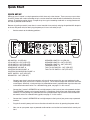
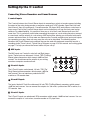
0
10
0
0
10
0
10
10
CONTROL ROOM MATRIX
A
U
D
I
O
C Class Signal Processors
SAMSON
Safety Instructions
Caution: To reduce the hazard of electrical shock, do not
remove cover or back.
CAUTION
FOR CONTINUED PROTECTION AGAINST RISK
OF FIRE, REPLACE ONLY WITH SAME TYPE FUSE
ATTENTION
No user serviceable parts inside. Please refer all servicing to qualified personnel.
UTILISER UN FUSIBLE DE
RECHANGE DE MÊME TYPE
WARNING
DO NOT EXPOSE THIS EQUIPMENT
TO RAIN OR MOISTURE
AVIS
RISQUE DE CHOC ELECTRONIQUE
NE PAS OUVRIR
RISK OF ELECTRIC SHOCK
DO NOT OPEN
WARNING: To reduce the risk of fire or electric shock, do not expose this unit to rain or moisture.
The lightning flash with an arrowhead symbol within an equilateral triangle, is intended to alert the user to the
presence of uninsulated "dangerous voltage" within the products enclosure that may be of sufficient magnitude
to constitute a risk of electric shock to persons.
The exclamation point within an equilateral triangle is intended to alert the user to the presence of important
operating and maintenance (servicing) instructions in the literature accompanying the product.
Important Safety Instructions
1. Please read all instructions before operating the unit.
2. Keep these instructions for future reference.
3. Please heed all safety warnings.
4. Follow manufacturers instructions.
5. Do not use this unit near water or moisture.
6. Clean only with a damp cloth.
7. Do not block any of the ventilation openings. Install in accordance with the manufacturers instructions.
8. Do not install near any heat sources such as radiators, heat registers, stoves, or other apparatus (including
amplifiers) that produce heat.
9. Do not defeat the safety purpose of the polarized or grounding-type plug. A polarized plug has two blades with
one wider than the other. A grounding type plug has two blades and a third grounding prong. The wide blade or
third prong is provided for your safety. When the provided plug does not fit your outlet, consult an electrician for
replacement of the obsolete outlet.
10. Protect the power cord from being walked on and pinched particularly at plugs, convenience receptacles and at
the point at which they exit from the unit.
11. Unplug this unit during lightning storms or when unused for long periods of time.
12. Refer all servicing to qualified personnel. Servicing is required when the unit has been damaged in any way,
such as power supply cord or plug damage, or if liquid has been spilled or objects have fallen into the unit, the
unit has been exposed to rain or moisture, does not operate normally, or has been dropped.
Table of Contents
Introduction
2
C•control Features
3
Controls and Functions
Front Panel Layout
Rear Panel Layout
4
5
Quick Start
Quick Set-up 6-7
Setting up the C•control
Connecting Stereo Recorders and Sound Sources
C•control Inputs
C•control Outputs
Connecting Line Level Speaker Outputs
8
9
9
Operating the C•control
11-14
C•control Typical Set-up
15
Stacking the C•control
16
C•control Wiring Guide
17
Specifications
18-19
C•class Dual Rack Adaptor (Optional)
20
Block Diagram
21
Copyright 2001, Samson Technologies Corp.
Printed November., 2002
Samson Technologies Corp.
575 Underhill Blvd.
P.O. Box 9031
Syosset, NY 11791-9031
Phone: 1-800-3-SAMSON (1-800-372-6766)
Fax: 516-364-3888
www.samsontech.com
Introduction
Congratulations on purchasing the C control, Control Room Matrix by Samson Audio! The C control is
a compact, high-quality device that provides the extensive control room monitoring features previously
only found in expensive large format recording consoles. The C control is the perfect solution for interfacing all your stereo line sources including mixers, hard-disk recorders, 2-tracks, along with multiple
sets control room monitors. The C control provides four sets of stereo line inputs, a headphone amplifier with level control and switching for three sets of control room monitors. The C control also provides a
sophisticated Talkback section, which includes an internal condenser microphone with the ability to
route the Talkback signal to the 2-Track outputs and to the External Que for headphones. Providing
silent switching and superb audio fidelity, the C control’s signal path will impress the most critical listeners.
Although this unit is designed for easy operation, we suggest you take some time out first to go through
these pages so you can fully understand how we’ve implemented a number of unique features. In this
manual, you’ll find a more detailed description of the features of the C control, as well as a guided tour
through the front and rear panels, step-by-step instructions for using the C control and full specifications. You’ll also find a warranty card enclosed—please don’t forget to fill it out and mail it so that you
can receive online technical support and so we can send you updated information about other Samson
products in the future.
With proper care and adequate air circulation, your C•control will operate trouble free for many years.
We recommend you record your serial number in the space provided below for future reference.
Serial number:
Date of purchase:
Should your unit ever require servicing, a Return Authorization number (RA) must be obtained before
shipping your unit to Samson. Without this number, the unit will not be accepted. Please call Samson at
1-800-3SAMSON (1-800-372-6766) for a Return Authorization number prior to shipping your unit.
Please retain the original packing materials and if possible, return the unit in the original carton and
packing materials.
2
C•control Features
SAMSON
0
10
0
10
0
10
0
10
The Samson C•control headphone amplifier utilizes the latest technology in gain management design. Here are
some of it’s features:
•
Speaker and input source selector providing a convenient centralized point for routing and listening to
stereo sources over various monitor speakers.
•
3-way line level speaker selector providing A/B or A/B plus C switching.
•
Three 2-track / Stereo Inputs can be used to connect DAT, CD, MINIDISK, sub-mixers, MIDI rigs or any
other stereo line level source.
•
Four stereo Source switches are used to route any of the connected stereo sources to the monitor output.
•
Headphone Output with Level control for listening.
•
Control Room VOLUME knob is used to adjust the overall level of the connected monitor speakers.
•
SPEAKER 2 VOLUME control is used to level match SPEAKER 1 and SPEAKER 2 so that they are at
the proper level when switched.
•
Talkback Mic with momentary TALK switch and LEVEL control picks up conversation from the engineer
and/or producer to talent over the CUE output.
•
TALK TO CUE switch, when engaged, routes the internal TALKBACK microphone to the CUE output
allowing the engineer and/or producer to talk to the talent on the other side of the glass.
•
TALK TO 2-TR switch, when engaged, routes the internal TALKBACK microphone to the 2-track outputs
allowing the engineer and/or producer to print a cue like “ soda jingle track seven” to the final two-track
mix.
•
Mono switch is used to check mixes for mono compatibility, and when engaged, all the input sources are
summed to a mono signal.
•
Mute switch provides a single button to silence all inputs and outputs.
•
Dim switch, when engaged, will lower the level of all outputs by 20dB.
•
Main Mix Stereo Input for connecting to main mixing console.
•
Three speaker Outputs, one 1/4 inch balanced line level and two RCA unbalanced line level output.
•
Four 2-track/Stereo inputs, three 1/4 inch balanced line level and one RCA unbalanced line level input.
•
Oversized, rubber bumpers with tilting feet allow several Samson C class units to be stacked and tilted in
an ergonomically correct operating position.
•
Three year extended warranty.
3
Controls and Functions
FRONT PANEL LAYOUT
1
2
4
3
SOURCE
6
5
7
9
8
TALKBACK
CONTROL ROOM
DESTINATION
SAMSON
OL
+6
MIX
2TK A
0
0
2TK B
2TK C
MUTE
10
TALK TO
CUE
DIM
HEADPHONE
VOLUME
-6
0
10
0
VOLUME
SPK B
VOLUME
SPEAKER A
SPEAKER B
-18
0
10
10
TALKBACK
LEVEL
SUB
TALK TO
2TK
-30
L
R
LEVEL
10
11
12
13
HEADPHONE
14
15
16
SPEAKER C
17
MIC
MONO
18
CONTROL ROOM
MATRIX
19
1
MIX SOURCE SWITCH - Used to assign the
main MIX input to the C controls SPEAKER,
CUE and HEADPHONE outputs.
12
LEVEL METER - Six segment LED bar VU
meter displaying the Input Level from –30db
to OL (peak)
2
2 TK A SOURCE - Used to assign the 2-track A
input to the C controls SPEAKER, CUE and
HEADPHONE outputs.
13
HEADPHONE JACK - Standard, 1/4-inch
stereo headphone jack allowing headphone
monitoring from C control’s internal headphone amplifier.
3
HEADPHONE VOLUME - Adjusts the output
level of the internal headphone amplifier.
14
SPEAKER A - When pressed, the switch turns
on the SPEAKER A outputs.
4
CONTROL ROOM VOLUME - Master level control for all speaker outputs.
15
SPEAKER B - When pressed, the switch turns
on the SPEAKER B outputs.
5
SPEAKER B VOLUME - Used to adjust and balance the SPEAKER B output level.
16
SPEAKER C/SUB - When pressed, the switch
turns on the SPEAKER C outputs.
6
MUTE SWITCH - When engaged, all of C control’s outputs are turned off.
17
7
DIM SWITCH - When engaged, the Control
Room output level is lowered by 20dB.
TALKBACK MICROPHONE - Internal condenser microphone used to record or send
cues from the control room.
18
TALK TO 2-TRACK - When pressed down, the
internal microphone is active and the output
signal of the microphone is routed to the 2track outputs.
19
POWER - Main power switch.
8
TALKBACK LEVEL - Used to control the output
level of the internal Talk-back microphone.
9
TALK TO CUE - When pressed down, the internal microphone is active and the output signal
of the microphone is routed to the CUE output.
10
2 TK B SOURCE - Used to assign the 2-track B
input to the C controls SPEAKER, CUE and
HEADPHONE outputs.
11
2 TK C SOURCE - Used to assign the 2-track C
input to the C controls SPEAKER, CUE and
HEADPHONE outputs.
4
Controls and Functions
REAR PANEL LAYOUT
+
-
A
DC INLET - The included AC/DC power supply
is connected here.
B
REMOTE TALK - 1/4-inch phone connector used
to connect external TALKBACK switch.
C
EXTERNAL CUE - Stereo output on two 1/4-inch
balanced phone connectors for sending C control left and right mix to a headphone amplifier.
D
SPEAKER C - Stereo RCA outputs for connecting
monitor power amplifier or powered monitors.
Also can be used to connect an external powered subwoofer.
E
SPEAKER B - Stereo RCA outputs for connecting
a monitor power amplifier or pair of powered
monitors.
F
SPEAKER A - Stereo 1/4-inch balanced outputs
for connecting a monitor power amplifier or pair
of powered monitors.
G
2-TRACK C OUTPUT - Stereo RCA outputs for
connecting any –10dBu level recording devices,
such as a computer sound card, minidisk or
consumer cassette recorder.
H
2-TRACK B OUTPUT - Stereo 1/4-inch balanced
outputs for connecting any +4dBu level recording devices, such as a DAT recorder, computer
sound card or CD burner.
5
I
2-TRACK A OUTPUT - Stereo 1/4-inch balanced outputs for connecting any +4dBu
level recording devices, such as a DAT
recorder, computer sound card or CD
burner.
J
2-TRACK C INPUT - Stereo RCA inputs for
connecting any –10dBu level recording
devices, such as a computer sound card,
minidisk, CD player or consumer cassette
recorder.
K
2-TRACK B INPUT - Stereo 1/4-inch balanced inputs for connecting any +4dBu
level stereo sources, such as a DAT
recorder, computer sound card, CD burner or sub-mixer.
L
2-TRACK A INPUT - Stereo 1/4-inch balanced inputs for connecting any +4dBu
level stereo sources, such as a DAT
recorder, computer sound card, CD burner or sub-mixer.
M
MIX INPUT - Stereo 1/4-inch balanced
inputs for connecting any +4dBu level
stereo sources, such as your main mixer
or hard disk.
Quick Start
QUICK SET-UP
Setting up your C control is a simple procedure, which takes only a few minutes. There are many ways to interface the C control with various recording set-ups, so take some time to decide which audio devices you want to
connect. The following section shows a simple set-up for a typical recording studio with an analog console and
two sets of powered studio monitors.
Remove all packing materials (save them in case of need for future service) and plug the provided AC adapter in
to the rear AC power inlet, but don’t plug the power pack into a wall outlet just yet.
•
Set the controls to the following positions:
SAMSON
MIX SWITCH - IN (LED ON)
2TK A SWITCH - OUT (LED OFF)
2TK B SWITCH - OUT (LED OFF)
2TK C SWITCH - OUT (LED OFF)
HEADPHONE VOLUME - 0
CONTROL ROOM VOLUME - 0
CONTROL ROOM SPKR B VOLUME - 0
MUTE SWITCH - OUT (LED OFF)
DIM SWITCH - OUT (LED OFF)
SPEAKER A SWITCH - IN (LED ON)
SPEAKER B SWITCH - OUT (LED OFF)
SPEAKER C SWITCH - OUT (LED OFF)
TALKBACK LEVEL - O
TALK TO CUE SWITCH - OUT (LED OFF)
TALK TO 2TK SWITCH - OUT (LED OFF)
•
Connect your mixer’s control room outputs, or the main stereo source that you want monitored, to the
Left/Right MIX input jacks on the C control’s rear panel. The C control accepts both balanced and unbalanced signals. Generally, a balanced signal is preferable because it provides better signal-to-noise ratio
and reduced extraneous noise. For a detailed wiring guide, see page 17 in this manual.
•
Connect the C control’s SPEAKER A left and right outputs to the inputs of your main powered monitors.
The SPEAKER A outputs are balanced, however it is possible to use balanced and unbalanced cables.
Generally, a balanced signal is preferable because it provides better signal-to-noise ratio and reduced
extraneous noise. For a detailed wiring guide, see page 17 in this manual.
•
Connect the C control’s SPEAKER B left and right outputs to the inputs of your power amp or powered
monitors.
•
Plug the C control’s power pack into a wall outlet and switch the unit on by pressing the power switch.
•
Now, turn on your power amps or powered studio monitors and set the level control to their normal positions.
6
Quick Start
QUICK SET-UP - Continued
®
®
®
SIGNAL FLOW
SIGNAL FLOW
SAMSON
POWER
AC IN
18V
1A
EXT CUE
SPK B
SPK C
SPK A
2TK B
2TK A
2TK C
2TK B
2TK A
MIX IN
L
L
BALANCED
+
2TK C
L
TALKBACK
REMOTE
SWITCH
BALANCED
BALANCED
BALANCED
BALANCED
BALANCED
BALANCED
LINE INPUTS
SIGNAL FLOW
SIGNAL FLOW
SIGNAL FLOW
SIGNAL FLOW
®
LINE OUTPUTS
-
500mA
R
R
R
OUTPUT
INPUT
SIGNAL FLOW
MIX OUTPUTS
MIC/LINE 1
MIC/LINE 2
MIC/LINE 3/4
MASTER SECTION
MIC/LINE 5/6
LEFT
LEFT/MONO
AUX RET
30
3/L
30
GAIN
5/L
LINE IN
SIGNAL FLOW
SIGNAL FLOW
SIGNAL FLOW
AUX OUT
LEFT
CR OUT
MIX OUT
RIGHT
RIGHT
LINE IN
GAIN
CLIP
CLIP
5
-26
+26
60
5
0
5
10
0
15
10
LF
5
0
5 80Hz
5
12K
15
10
LF
5
0
15
10
5 80Hz
LF
5
0
5 80Hz
MAXIMUM
DYNAMIC
RANGE
15
5
MF
5
2T IN
5 2.5K
10
2T OUT
10
15
15
12K
10
15
5 2.5K
0
MONO OUT
HF
5
10
MF
5
10
15
15
5
12K
10
15
5 2.5K
0
RIGHT
0
HF
5
10
MF
5
10
15
15
0
HF
5
10
15
5 2.5K
0
6/R
4/R
60
10
MF
5
10
15
+26
5
12K
10
15
-26
0
HF
5
0
15
LEFT
RIGHT
LEFT
0
RIGHT
MONO 10
LF
5
5 80Hz
2TK TO MIX
10
10
10
10
10
10
10
5
10
HDR
15
15
15
15
AUX
15
15
AUX
15
POWER
15
AUX
AUX
0
PEAK
10
48V
+6
0
0
10
0
0
10
PAN
0
0
10
PAN
0
0
10
BAL
AUX RETURN
0
5
BAL
-6
-20
R
L
5
0
5
_
_
_
_
_
_
_
_
R
L
REC
10
10
5
5
0
0
5
5
_
_
_
_
_
_
_
_
R
L
10
10
5
5
0
0
5
5
_
_
_
_
_
_
_
_
R
L
REC
REC
10
0
10
MASTER SECTION
REC
10
10
5
5
0
0
5
5
MIX/2T
10
_
_
_
_
_
_
_
_
5
0
10
10
5
C/ROOM
+PHONES
0
5
5
0
10
10
5
5
_
_
_
_
_
_
_
_
0
5
5
_
_
_
_
_
_
_
_
0
5
10
10
10
10
10
10
10
10
10
10
10
15
15
15
15
15
15
15
15
15
15
15
20
20
20
20
20
20
20
20
20
20
20
30
40
30
40
30
40
30
40
30
40
30
40
30
40
30
40
30
40
30
40
CHANNEL 1
CHANNEL 2
CHANNEL 3/4
CHANNEL 5/6
PHONES
L
MIX
30
40
R
•
Run a stereo signal (like the output a CD player) into your mixer and raise the master level to about
“0dB”.
•
Once you have a good level set, turn your mixer’s control room volume control until the C control’s
LEVEL meter reaches about “0dB”.
•
Slowly raise the C control’s Control Room VOLUME knob until your main studio monitors reach the
desired listening level.
•
To select the secondary monitors, press the Speaker B switch in so that the green LED is illuminated.
•
Now, when you press the SPEAKER B switch off, you are selecting the secondary monitors and also
switching off the main monitors.
•
Slowly raise the SPK B LEVEL control until you reach the level you like.
Note: If you want to set the two pairs of monitors to the same level, switch the A/B and use the SPK B
LEVEL control to adjust the balance.
7
Setting-Up the C•control
Connecting Stereo Recorders and Sound Sources
C control Inputs
The C control features four 2-track /Stereo inputs for connecting a variety of sounds sources including
the output of the main mixing console or computer sound card, a DAT recorder, Open Reel Half-track
(dust them off, they still sound great), Cassette recorder, CD player, MIDI workstation or sub mixers to
name some. Each of the C controls stereo inputs can be turned on or off from the front panel assign
switches. For added flexibility, it is possible to have any or all of the 2-track /Stereo inputs on at the
same time. This is particularly useful when connecting the outputs of a main mixing console or computer sound card, and the outputs of a sub-mixer or MIDI workstation allowing you to monitor both sound
sources and control them as if they were one. Because the C control provides many inputs and outputs
for connecting your gear, there are many ways the unit can be interfaced. The following section
describes the 2-track /Stereo inputs and how they can be used with equipment commonly found in a
recording studio. There is also a “Typical Set-up” diagram on page 15 of this manual and a wiring guide
on page 17 to help you choose the correct cables for your set-up.
1 MIX Inputs
The MIX inputs are C control’s main Left and Right stereo
inputs. These inputs are balanced, 1/4-inch, TRS (Tip/Ring/
Sleeve) phone connectors which accept +4dB line level
sources. You should connect the outputs of your mixing
console or computer sound card here.
4
3
2
1
2 2-track A Inputs
The 2-Track A inputs are balanced, 1/4-inch, TRS (Tip/
Ring/ Sleeve) phone connectors which accept +4dB line
level sources. You can interface a professional DAT
machine or CD recorder here.
3 2-track B Inputs
The inputs labeled 2-Track B are balanced 1/4 inch,TRS (Tip/Ring/Sleeve) connectors which accept
+4dB line level sources. You can connect the outputs of a sub mixer, a professional DAT machine, or a
CD recorder here.
4 2-track C Inputs
The 2-Track C inputs are unbalanced, RCA connectors which accept -10dB line level sources. You can
connect the outputs of a sub mixer, cassette recorder or CD player here.
8
Setting-up the C•control
C control 2-Track Line Outputs
The C control features three 2-track /Stereo outputs allowing you to connect the inputs of a variety of
recording devices such as DAT recorders, Open Reel Half-tracks, Cassette recorders or CD
players/burners. The signal that is assigned in the C controls Source section is always present at all
the 2-track outputs, and is always at full strength and not affected by the Control Room level knob. To
avoid feedback loop problems, be sure to match the 2-track outputs with the associated 2-track inputs.
In other words, if you connect your DAT recorder to the 2-track A inputs, be sure to connect 2-track A
outputs to the DAT recorder’s inputs. C control provides many inputs and outputs for connecting your
gear, so there are many ways the unit can be interfaced. The following section describes the 2-Track
outputs and how they can be used with equipment commonly found in a recording studio. There is also
a “Typical Set-up” diagram on page 15 of this manual and a wiring guide on page 17 to help you
choose the correct cables for your set-up.
5 2-track A Outputs
The 2-Track A outputs are balanced, 1/4-inch, TRS (Tip/ Ring/ Sleeve) phone connectors which output
a +4dB line level signal. You can interface a professional DAT machine, Open Reel Half-track or CD
burner here.
6 2-track B Outputs
The outputs labeled 2-Track B are balanced, 1/4 inch, TRS(Tip/Ring/Sleeve)
connectors which output +4dB line level signal. You can use these outputs to
connect the inputs of a consumer cassette or CD recorder here.
7
6
5
7 2-track C Outputs
The 2-Track C inputs are unbalanced, RCA connectors which accept -10dB
line level sources. You can use these outputs to connect the inputs of a consumer cassette or CD recorder here.
Connecting Line Level Speaker Outputs
The C control provides three sets of line level outputs for connecting up to three pairs of studio monitors. The Speakers outputs are selected from the front panel speaker selection switches. Speaker
Outputs A and B are switched and are typically used to switch between a pair of near-field and far or
mid-field monitors. Speaker Output C/Sub can be independently turned on or off, so it is ideal for connecting a sub woofer that you may want to turn on for a big “hyped club” sound, but turn off for critical
mixing. There is more information on the speaker switching feature in the section “Operating C control”
following later in this manual. There is also a “Typical Set-up” diagram on page 15 of this manual and a
wiring guide on page 17 to help you choose the correct cables for your set-up.
9
Setting-up the C•control
8 Speaker A
The Speaker A outputs are balanced, 1/4-inch, TRS (Tip/ Ring/ Sleeve) phone connectors which output a +4dB line level signal. You can connect to an active studio monitor or power amplifier here.
IMPORTANT NOTE: In order to maintain the best gain structure and signal to noise ratio, we highly
recommend that only balanced cables be used on the SPEAKER A outputs. For detailed balanced
cable wiring diagrams, please see page 17 in this manual.
9 Speaker B
The Speaker B outputs are unbalanced, RCA connectors which output -10dB line level signal. You can
connect to an active studio monitor, multimedia speaker or power amplifier here.
10 Speaker C
11
The Speaker C outputs are unbalanced, RCA connectors, which output -10dB line level signal. You can connect to an active studio monitor, multimedia speaker
or power amplifier here.
11 External Cue Output
10
9
8
13
+
-
12
The External Cue outputs are balanced, 1/4-inch,
TRS (Tip/ Ring/ Sleeve) phone connectors which output a +4dB line level signal. This output is used to
connect the signal from the Talkback microphone to your headphone cue mix. Many good headphone
amplifiers such as the Samson C cue 8 or Samson S phone provide an auxiliary input so that you can
mix in the signal from the talkback mic with the stereo cue mix from your mixing console. This convenient feature allows the engineer and/or producer to talk to the talent over the headphone mix. There is
more information on the Talkback feature in the section “Operating C control” following later in this
manual.
12 TALK REMOTE
The C control’s TALKBACK microphone can be turned on and off from an external switch connected to
the TALK REMOTE input. The 1/4-inch phone jack is wired, “normally-open”, so a switch that shorts
the TALK REMOTE jack’s TIP to its SLEEVE will turn the TALKBACK microphone on and off in a
momentary action. This will allow the producer to move freely about the studio while talking to the talent.
13 AC INLET
The AC Inlet is where the C control receives it power from the included 18-volt AC power supply. Be
sure to use only the Samson AC1800 when operating the C control.
.
10
Operating the C•control
Operating the C Control
Once you have connected your stereo recorders, stereo sound sources and studio monitor speakers
you can begin to use, and enjoy the powerful features of the C control. The following section will take
you through the operation of the C control’s switches, control knobs and operating functions.
Controls and Functions
SAMSON
14 POWER switch
Use the POWER switch to turn the C control on and off. When the POWER
switch is set to the on position, the unit will power up and the green LED on the
POWER switch will illuminate indicating the unit is ready for operation.
TO
E
14
TO
K
CONTROL ROOM
MATRIX
Source Assignment Switches
When you engage any of the Source assignment switches, their associated LED’s will illuminate indicating the signal connected to that Source input is on and will now be heard on all outputs including the
selected SPEAKER outputs, the HEADPHONE and the EXTERNAL CUE outputs. C control allows you
to monitor more than one stereo Source at the same time, therefore a Source assignment switch will
stay on when another is selected. Simply press the source assignment button a second time and the
Source will turn off.
15
15 MIX Switch
16DESTINA
SOURCE
The MIX switch is used to assign the audio signal from the device connected to
the left and right MIX inputs to the monitor bus.
MIX
2TK A
2TK B
2TK C
17
18
16 2 TK A Switch
L
Use the 2TK A switch to assign the signal connected to the left and right 2track A inputs to the main stereo monitor bus.
17 2 TK B Switch
Used to assign the signal connected to the left and right 2 TK B inputs to the monitor bus.
18 2 TK C Switch
Used to assign the signal connected to the left and right 2 TK C inputs to the monitor bus.
19 Master Level Meter
DESTINATION
The C control’s master section includes an 6-segment LED LEVEL meter, which
displays the input level of the main left and right bus in decibels (dBs) from –30 to
Overload(OL). The signal displayed on the LEVEL meter shows the level of the
combined signals of all of the two track inputs. If the LEVEL meter displays a
clipped signal, then turn down the signal or signals being sent into the stereo bus.
OL
+6
2TK A
0
-6
2TK C
-18
-30
L
R
LEVEL
19
11
LE
Operating the C•control
Using the Headphone Amplifier
The C control includes an internal headphone amplifier for monitoring the mix and/or any of the
assigned two-track inputs.
WARNING: Because the C control is capable of generating high volume levels, always start with the
HEADPHONE VOLUME knob at minimum and then slowly turn it up until you reach a comfortable listening level.
20 Headphone Volume
The HEADPHONE VOLUME control is used to adjust the level of the headphones connected to the front panel HEADPHONE jack. The signal feeding
the headphone is picked up before the MUTE switch, therefore it is possible to
listen to the headphones while the connected monitors are off.
20
0
10
HEADPHONE
VOLUME
21 Headphone Jack
The C control’s HEADPHONE output accepts standard 1/4-inch, stereo TRS
(Tip/ Ring/ Sleeve) phone plugs for connecting headphones. You can connect
any standard headphone from 8 through 240 Ohms.
HEADPHONE
21
Control Room Section
22 Volume
The C control’s VOLUME knob is the master control for the Control Room level. Use the VOLUME knob
to adjust the overall level of all the SPEAKER outputs.
23
22
23 Speaker B Volume
CONTROL ROOM
MUTE
DIM
The SPEAKER B volume control is used to adjust the level of the
SPEAKER B output and works in conjunction with the Control
Room VOLUME knob. This means if the Control Room Volume is
set all the way off (fully counter clockwise), there will be no output
on Speaker B, regardless of the level set on the SPEAKER B control knob. Use the SPEAKER B control knob to adjust the balance
between the monitors connected to the SPEAKER A outputs and the monitors connected to SPEAKER
B outputs.
0
10
0
10
VOLUME
SPK B
VOLUME
SPEAKER A
SPEAKER B
SUB
SPEAKER C
MONO
To set the balance between the monitors connected to the SPEAKER A and SPEAKER B outputs, first
turn the Control Room VOLUME to a low level and set the SPEAKER B level all the way off (fully
counter clockwise). Be sure that the SPEAKER B output is active by engaging the SPEAKER B switch
(the green LED will illuminate). Now, press the SPEAKER A switch on and off while adjusting the
SPEAKER B Volume Control, matching the level of the two sets of monitors. Once you have matched
the balance, use the Control Room VOLUME knob to adjust the overall level of either set of monitors.
12
Operating the C•control
Setting the SPEAKER C/SUB Level
The Control Room VOLUME knob is used to adjust the level of the
SPEAKER C output exclusively. To set the balance between the
SPEAKER A/B, use the input level control on your power amp, powered monitor or sub woofer amplifier.
CONTROL ROOM
0
10
0
24
25
MUTE
DIM
10
VOLUME
SPK B
VOLUME
SPEAKER A
SPEAKER B
24 MUTE switch
SUB
SPEAKER C
MONO
The mute switch provides a convenient way to shut off any and all
27
28
29
26
of the SPEAKER outputs with a single button push. When the
MUTE switch is engaged, the red LED will illuminate indicating that
there is no signal present at the SPEAKER outputs. While all of the speaker outputs are off when the
MUTE switch is engaged, the HEADPHONE output and EXTERNAL CUE outputs are still active.
25 Dim switch
The C control offers a useful feature, DIM, allowing you to lower the overall Control Room level with the
press of a single button. When the DIM switch is pressed to the on position, the yellow LED will illuminate and the overall level of any and all of the connected monitors will be lowered by 20dB. This allows
you quickly turn the speaker levels down to talk to someone in the control room or on the phone, without having to shut the speakers completely off.
26 Mono switch
With C control, it’s easy to check your mixes for mono compatibility thanks to the Mono function. To listen to your mix in mono, simply press the MONO switch and the yellow LED will illuminate indicating all
the outputs are receiving a mono signal.
27 SPEAKER A Assign Switch
The speaker A switch can operated in two different ways depending on the position of the Speaker B
switch. If the SPEAKER B switch is not assigned (LED off), then the SPEAKER A switch simply turns
the SPEAKER A output on and off. When the LED is illuminated, the output is active and you will hear
the monitors connected to the SPEAKER A outputs. If the SPEAKER B assign switch is engaged (LED
is illuminated), the SPEAKER A switch will function as an A/B toggle switch selecting between the monitors connected to the SPEAKER A and SPEAKER B outputs.
28 SPEAKER B Assign Switch
When the SPEAKER B switch is engaged (LED is on), the SPEAKER B outputs can be turned on by
using the SPEAKER A switch to toggle between the SPEAKER A and SPEAKER B outputs. See the
previous section “SPEAKER A Assign Switch” for more information on selecting between SPEAKER A
and SPEAKER B.
29 Speaker C Assign Switch/SUB
The SPEAKER C/SUB switch is used to turn on the monitors or subwoofer connected to the SPEAKER
C outputs. The SPEAKER C assign switch works independently from the SPEAKER A and/or SPEAKER B switch, so it is an ideal output to use for a subwoofer. Since the SPEAKER C switch works independently, you can leave a subwoofer on while listening to either the SPEAKER A or SPEAKER B
monitors, and easily turn it on or off.
13
Operating the C•control
TALKBACK SECTION
29 TALKBACK MICROPHONE
The C control features an internal condenser microphone located on the front panel, which can be
used to record an audio cue on the connected 2-tracks, or to communicate with other musicians, or
other talent, listening to the mix on the EXTERNAL CUE outputs. The following sections detail how to
route the signal, and control the level of the TALKBACK MICROPHONE.
30 Talk To 2-Track
The TALK TO 2-Track switch is used to assign the TALKBACK MIC to the 2Track outputs. This allows the engineers and producers in the studio control
room to record an audio cue on the any of the connected 2-Track recorders.
The TALK TO 2-track switch has a “momentary” action, so you must press
and hold the switch while talking or recording the TALKBACK MIC to the 2tracks.
31 Talk To Cue
32
TALKBACK
31
SA
TALK TO
CUE
0
10
TALKBACK
LEVEL
TALK TO
2TK
CON
MIC
30
29
The TALK TO CUE switch is used to assign the TALKBACK MIC to the EXTERNAL CUE output. This
allows the engineers and producers in the studio control room to communicate with the musicians in
the recording room. The TALK TO CUE switch has a “momentary” action, so you must press and hold
the switch while talking or recording the TALKBACK MIC.
32 Talkback Level
The TALKBACK LEVEL control is used to adjust the volume of the signal that is picked up from the
internal TALKBACK MICROPHONE. Keep in mind that there is more than likely someone monitoring
the EXTERNAL CUE output on headphones when you press TALK TO CUE, so be sure to start at a
low level. When using the Talk to 2-track switch, adjust the level of the TALKBACK MICROPHONE by
checking the connected 2-tracks input level meters.
Using The Remote Talkback Function
You can remote control the Talkback switch by using a momentary switch connected to the TALK
REMOTE jack located on the rear panel. A standard footswitch, available at your local music retailer, or
wired remote switches like the Switchcraft SERIES ED900 can be used to conveniently engage the
talkback circuit without actually touching the C control. Below is a wiring diagram for the REMOTE
TALK switch.
REMOTE TALKBACK SWITCH WIREING
Tip (+)
NORMALLY
OPEN MOMENTERY
SWITCH
Sleeve (common)
14
SIGNAL FLOW
15
2 CH
0
0
10
10
VOLUME
10
VOLUME
0
CH 4
SHAPE OUT
10
VOLUME
-12
-24
CH 2
-18
-12
-6
-18
10
10
VOLUME
0
SHAPE OUT
-24
0
0
-6
-24
SHAPE OUT
SHAPE OUT
-18
-12
-6
STEREO
L
R
BALANCE
CH 3
0
CH 3
OL
CH 2
0
5
5
5
+26
HF
12K
MF
10
LF
5
5
5
5
0
30
40
15
20
30
40
15
20
30
40
+26
REC
0
0
0
0
5
HF
12K
MF
10
LF
R
30
40
20
15
10
5
0
5
10
PAN
10
AUX
15
10
5 80Hz
15
10
5 2.5K
15
5
5
5
_
_
_
_
_
_
_
_
REC
0
0
0
5
HF
12K
MF
10
LF
R
30
40
20
15
10
5
0
5
10
BAL
10
AUX
15
10
5 80Hz
15
10
5 2.5K
15
CHANNEL 3/4
30
40
20
15
10
5
0
5
10
L
0
15
10
15
10
15
10
0
LINE IN
5
5
5
_
_
_
_
_
_
_
_
REC
0
0
0
0
LINE IN
5
HF
12K
MF
10
LF
R
30
40
20
15
10
5
0
5
10
BAL
10
AUX
15
10
5 80Hz
15
10
5 2.5K
15
CHANNEL 5/6
30
40
20
15
10
5
0
5
10
L
0
15
10
15
10
15
10
6/R
5/L
MIC/LINE 5/6
0
0
5
10
10
PHONES
0
5
C/ROOM
+PHONES
MIX/2T
10
HDR
LEFT
RIGHT
2T OUT
DYNAMIC
30
40
-6
0
-20
MIX
20
30
40
15
20
15
5
0
5
10
10
L
_
_
_
_
_
_
_
_
0
5
R
30
40
20
15
10
5
0
5
10
POWER
MONO 10
_
_
_
_
_
_
_
_
PEAK
48V
+6
10
5
0
5
10
MONO OUT
AUX OUT
RANGE
MASTER SECTION
RIGHT
AUX RETURN
5
2TK TO MIX
LEFT
2T IN
RIGHT
MIX OUT
CR OUT
RIGHT
LEFT
LEFT
MASTER SECTION
MAXIMUM
RIGHT
AUX RET
LEFT/MONO
SIGNAL FLOW
SIGNAL FLOW
SOUND CARD
OUTPUTS
SIGNAL FLOW
CHANNEL 2
_
_
_
_
_
_
_
_
-26
4/R
3/L
MIC/LINE 3/4
MIX OUTPUTS
SIGNAL FLOW
SIGNAL FLOW
SIGNAL FLOW
CHANNEL 1
15
20
10
10
10
5
5
5
10
5
L
0
15
10
15
10
15
10
0
R
PAN
10
AUX
15
10
5 80Hz
15
10
5 2.5K
10
0
_
_
_
_
_
_
_
_
5
15
5
REC
0
0
0
0
10
L
0
15
10
15
10
15
10
-26
CLIP
5
GAIN
60
30
30
5
CLIP
60
MIC/LINE 2
MIC/LINE 1
4 CHANNEL
HEADPHONE AMP
GAIN
CH 4
LINE INPUTS
OL
CH 1
-
0
CH 1
+
SIGNAL FLOW
OL
MAIN
SIGNAL FLOW
SIGNAL FLOW
SIGNAL FLOW
®
SIGNAL FLOW
INJECT
0
10
VOLUME
®
®
SIGNAL FLOW
SIGNAL FLOW
SOUND CARD
INPUTS
SIGNAL FLOW
SIGNAL FLOW
LINE INPUTS
®
SIGNAL FLOW
SIGNAL FLOW
LINE OUTPUTS
LINE OUTPUTS
The following diagram shows a typical studio set up with C control interfaced to a mixer, two sets of studio monitors with subwoofer, a DAT
machine, MIDI workstation, headphone amplifier and computer hard-disk recorder. Remember, there are many different ways to interface
your C control, so your set-up will more than likely be different.
C•control Typical Set-up
CUE MIX SET-UP FOR MULTITRACK VOCAL RECORDING
SIGNAL FLOW
SIGNAL FLOW
Stacking and Tilting the C•control
Stacking the C•control
SOURCE
TALKBACK
CONTROL ROOM
DESTINATION
SAMSON
OL
You can stack one C control,
or any other Samson C Class
units, on top of each other by
simply lining up the bumpers.
Important Note: When stacking
the C control, be sure that only
the bottom unit has the tilting
feet installed.
+6
MIX
2TK A
2TK B
2TK C
0
0
MUTE
10
TALK TO
CUE
DIM
HEADPHONE
VOLUME
-6
0
10
SPK B
VOLUME
SPEAKER A
SPEAKER B
-18
0
10
0
VOLUME
10
TALKBACK
LEVEL
SUB
TALK TO
2TK
-30
L
R
HEADPHONE
LEVEL
SOURCE
SPEAKER C
TALKBACK
CONTROL ROOM
DESTINATION
CONTROL ROOM
MATRIX
MIC
MONO
SAMSON
OL
+6
MIX
2TK A
0
0
MUTE
10
2TK B
2TK C
TALK TO
CUE
DIM
HEADPHONE
VOLUME
-6
10
0
VOLUME
SPK B
VOLUME
SPEAKER A
SPEAKER B
-18
0
10
0
10
TALKBACK
LEVEL
SUB
TALK TO
2TK
-30
L
R
HEADPHONE
LEVEL
SPEAKER C
MONO
•
Remove the bottom screw from right front bumper.
•
Identify the right tilting foot by the locating “R” marking on the inside top.
•
Position the angled foot under the right bumper as shown in the drawing.
MIC
Installing the Tilting Feet
BACK
You can install the tilting rubber feet included with
your C control so that you can set the unit at a
comfortable operating angle on a workstation or
desktop. Follow the simple instructions below to
install the tilting feet.
SAMSON
TALK TO
CUE
10
K
•
Remove the bottom screw from right front
bumper.
•
Identify the right tilting foot by the locating
“R” marking on the inside top.
•
Position the angled foot under the right
bumper as shown in the drawing.
•
Use the included 4 x 10mm screw to attach
the foot.
•
Repeat the steps above for the front left
bumper.
MIC
16
TALK TO
2TK
CONTROL ROOM
MATRIX
CONTROL ROOM
MATRIX
C•control Wiring Guide
C control Wiring Guide
There are several ways to interface the C control, depending on your exact monitoring set-up. Follow the cable
diagrams below for connecting your monitor system.
RCA to RCA Cable
Tip (signal)
Tip (signal)
Tip (signal)
Sleeve (ground)
Sleeve (ground)
Sleeve (ground)
Un-Balanced 1/4” to 1/4” Cable
Signal
Tip (signal)
Ground
Ground
Sleeve (ground)
Signal
Signal
Signal
Ground
Ground
Tip (signal)
Sleeve (ground)
Balanced 1/4” to 1/4” Cable
Signal (ring)
Tip (signal) Ring (signal)
Signal (tip)
Ground
Sleeve (ground)
Ground
Signal (ring)
Tip (signal)
Ring (signal)
Signal (tip)
Signal (ring)
Signal (tip)
Signal (tip)
Signal (ring) Ground
Ground
Sleeve (ground)
Balanced XLR to XLR Cable
Hot (2) Common (1)
1
2
2
3
End View
Common
Hot
Hot
Common (1) Hot (2)
Common
1
1
3
2
3
Solder Points
Solder Points
Cold (3)
Cold
Cold
Female XLR
Male XLR
Cold (3)
Unbalanced 1/4” to RCA Cable
Tip (signal)
Tip (signal)
Sleeve (ground)
Tip (signal)
Sleeve (ground)
Sleeve (ground)
Un-Balanced XLR to RCA Cable
Tip (signal)
Hot (2) Common (1)
1
2
3
End View
2
Tip (signal)
1
3
Cold (Pin 3)
(no connection)
Solder Points
Cold (3)
Sleeve (ground)
Male XLR
17
2
1
3
End View
Specifications
Specifications
Global Specifications
Frequency response
Noise
THD
10 Hz to 32 kHz, +0/- 3 dB
> 90 dB, unweighted, 22 Hz to 22 kHz
0.008 % typ. @ +4 dBu, 1 kHz
Control Knobs
Control Room Level
Speaker B Level
Headphone Level
Talkback Level
Rotary Variable Resistor, Audio Taper
Rotary Variable Resistor, Audio Taper
Rotary Variable Resistor, Audio Taper
Rotary Variable Resistor, Audio Taper
Function switches
MIX Assignment Switch
2TK A Assignment Switch
2TK B Assignment Switch
2TK C Assignment Switch
SPEAKER A Switch
SPEAKER B Switch
SPEAKER C/SUB Switch
TALK TO CUE Switch
TALK TO 2TK Switch
MUTE Switch
DIM Switch
Mono Switch
Power Switch
Push Switch, Green LED indicator
Push Switch, Green LED indicator
Push Switch, Green LED indicator
Push Switch, Green LED indicator
Push Switch, backlit Green LED indicator
Push Switch, backlit Green LED indicator
Push Switch, backlit Green LED indicator
Push Switch, backlit Green LED indicator
Push Switch, backlit Green LED indicator
Push Switch, backlit Red LED indicator
Push Switch, backlit Yellow LED indicator
Push Switch, backlit Yellow LED indicator
Rocker, backlit Green LED
Front Panel Connectors
Headphone Output
1/4-Inch Phone, TRS
Rear Panel Connectors
Inputs
MIX IN Left and Right
2TK A IN Left and Right
2TK B IN Left and Right
2TK C IN Left and Right
1/4-Inch Phone, balanced, TRS
1/4-Inch Phone, balanced, TRS
1/4-Inch Phone, balanced, TRS
RCA, unbalanced
Line Outputs
2TK A OUTPUT Left and Right
2TK B OUTPUT Left and Right
2TK C OUTPUT Left and Right
1/4-Inch Phone, balanced, TRS
1/4-Inch Phone, balanced, TRS
RCA, unbalanced
Speaker Outputs
SPEAKER A OUTPUT Left and Right
SPEAKER B OUTPUT Left and Right
SPEAKER C/SUB OUTPUT Left and Right
1/4-Inch Phone, balanced, TRS
RCA, unbalanced
RCA, unbalanced
18
Specifications
Specifications - contuniued
Control
Remote Talkback Switch
1/4-Inch TRS
Microphone
1. Talkback Microphone
Internal condenser
Metering
Input Level
Six Segment, LED VU Meter (OL, +6, 0, -6, -18, -30)
Power Supply
Mains Voltages USA/Canada
Mains Voltages Europe
Power Inlet
Power Consumption
105-125 VAC ~, 60 Hz
215 – 254 VAC~,50Hz
Standard IEC receptacle / with fuse
29 Watts Max.
Physical
Dimensions
Net Weight
Shipping Weight
1 3/4" (44.5 mm) * 19" (482.6 mm) * 8 1/2" (217 mm)
5.5lbs., (2.5 kg)
8lbs., (3.6 kg)
19
C•Class Dual Rack Adaptor (optional)
The C Class Dual Rack Adaptor is available as an accessory from an authorized Samson dealer or through
our website: www.samsontech.com.
1. Disconnect any cables, that may be connected, from the C•Class unit to be mounted, i.e., the power
supply cable, audio cables, headphones.
2. Align the holes in the C•Rack with the holes on the bottom of of the C•Class unit to be mounted. Use
the supplied phillips head M4 machine screws to fix the unit to the rack as shown below.
3. Repeat steps 1 and 2 to mount the second C•Class unit if desired.
4. Once the units are mounted on the C• Rack, the assembly can be placed into a rack and secured via the
rack ears. (Screws not supplied)
5. To remove the C•Class unit from the C•Rack, reverse the instructions above.
If you experience any difficulties, or require further assistance, contact Samson Customer Service at 1-8003SAMSON (1-800-372-6766) M–F 9AM to 5PM (eastern standard time). For more product information please
visit our website at www.samsontech.com.
20
C•control Block Diagram
Samson Technologies Corp.
575 Underhill Blvd.
P.O. Box 9031
Syosset, NY 11791-9031
Phone: 1-800-3-SAMSON (1-800-372-6766)
Fax: 516-364-3888
www.samsontech.com