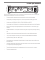
1
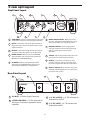
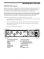
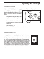
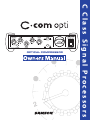
-5
-3
-2 -1
0
-20
+4
VU
SAMSON
OPTICAL COMPRESSOR
A
U
D
I
O
C Class Signal Processors
-7
-10
Safety Instructions
Caution: To reduce the hazard of electrical
shock, do not remove cover or back.
No user serviceable parts inside. Please refer all
servicing to qualified personnel.
WARNING: To reduce the risk of fire or electric shock, do not expose this unit to rain or moisture.
The lightning flash with an arrowhead symbol within an equilateral triangle, is intended to alert the user to the
presence of uninsulated "dangerous voltage" within the products enclosure that may be of sufficient magnitude to
constitute a risk of electric shock to persons.
The exclamation point within an equilateral triangle is intended to alert the user to the presence of important operating and maintenance (servicing) instructions in the literature accompanying the product.
Important Safety Instructions
1.
Please read all instructions before operating the unit.
2.
Keep these instructions for future reference.
3.
Please heed all safety warnings.
4.
Follow manufacturers instructions.
5.
Do not use this unit near water or moisture.
6.
Clean only with a damp cloth.
7.
Do not block any of the ventilation openings. Install in accordance with the manufacturers instructions.
8.
Do not install near any heat sources such as radiators, heat registers, stoves, or other apparatus
(including amplifiers) that produce heat.
9.
Do not defeat the safety purpose of the polarized or grounding-type plug. A polarized plug has two
blades with one wider than the other. A grounding type plug has two blades and a third grounding
prong. The wide blade or third prong is provided for your safety. When the provided plug does not fit
your outlet, consult an electrician for replacement of the obsolete outlet.
10.
Protect the power cord from being walked on and pinched particularly at plugs, convenience receptacles and at the point at which they exit from the unit.
11.
Unplug this unit during lightning storms or when unused for long periods of time.
12.
Refer all servicing to qualified personnel. Servicing is required when the unit has been damaged in any
way, such as power supply cord or plug damage, or if liquid has been spilled or objects have fallen into
the unit, the unit has been exposed to rain or moisture, does not operate normally, or has been
dropped.
Table of Contents
Introduction
C com opti Features
4
5
Controls and Functions
Front Panel Layout
Rear Panel Layout
6
6
Operating the C com opti
Setting Up the C com opti
Compressing A Signal
Using the Enhancer
7
8
9
System Set-ups
10
Dynamics Processing 101
11
Applications
12
C com opti Connections
13
Stacking and Installing the Tilting Feet
14
Installing the Optional CRK1 Dual Rack adapter
15
Specifications
16
C com opti Block Diagram
17
Copyright 2003, Samson Technologies Corp.
Printed June, 2003
Samson Technologies Corp.
575 Underhill Blvd.
P.O. Box 9031
Syosset, NY 11791-9031
Phone: 1-800-3-SAMSON (1-800-372-6766)
Fax: 516-364-3888
www.samsontech.com
Introduction
Congratulations on purchasing the C com opti, optical compressor by Samson Audio! The C com
opti is a compact, high-quality device that provides extensive dynamics processing with a classic and
musical response and with the warm sound that only a photo cell compressor can offer. Easy operation makes the C com opti the perfect solution for dynamics processing in live sound and in recording applications for tracking, mixing and mastering. Whether you use a small amount of compression
to control level, or a drastic amount of compression for a intense retro effect, the C com opti will
delive rthe contrl and emotion. And for you tweekazoids, there is full manual control with variable
Threshold, Ratio, Attack and Release parameters. In addition, the C com opti offers a powerful
ENHANCE circuit, which when engaged, adds a pleasant restoration of the high frequencies that can
sometimes be diminished during heavy gain reduction. To help you monitor and set the best levels,
the C com opti features an easy-to-read, back-lit, analog VU meter which can be switched to display
Output Level or Gain Reduction. For stereo operation, two C com opti’s can be joined together using
the LINK input allowing the two units to operate as one stereo device. Like all Samson Audio C class
processors, the C com opti can be stacked on other C class models, and can be set-up on an angle
using the included tilting feet. The C com opti is also a half-single rack space unit and can be rack
mounted using the Samson CRK1. Most importantly, by providing transparent gain control and
superb audio fidelity, the C com opti’s signal path will impress the most critical listeners.
Although this unit is designed for easy operation, we suggest you take some time out first to go
through these pages so you can fully understand how we’ve implemented a number of unique features. In this manual, you’ll find a more detailed description of the features of the C com opti, as well
as a guided tour through the front and rear panels, step-by-step instructions for using the C com opti
and full specifications. You’ll also find a warranty card enclosed—please don’t forget to fill it out and
mail it so that you can receive online technical support and so we can send you updated information
about other Samson products in the future.
With proper care and adequate air circulation, your C com opti will operate trouble free for many
years. We recommend you record your serial number in the space provided below for future reference.
Serial number:
Date of purchase:
Should your unit ever require servicing, a Return Authorization number (RA) must be obtained
before shipping your unit to Samson. Without this number, the unit will not be accepted. Please call
Samson at 1-800-3SAMSON (1-800-372-6766) for a Return Authorization number prior to shipping
your unit. Please retain the original packing materials and if possible, return the unit in the original
carton and packing materials.
4
C com opti Features
-7
-5
-3
-2 -1
0
-10
-20
+4
VU
SAMSON
The Samson C com opti optical compressor utilizes a unique photo cell design which produces a classic sound while handling the job of gain management . Here are some of its main features:
•
Full featured, optical compressor dynamics processor ideal for live sound and recording.
•
Unique photo gain cell design offering classic, musical response while controling signal levels.
•
Variable control of THRESHOLD, RATIO, ATTACK, RELEASE and OUTPUT.
•
Large analog, back-lit VU Meter that can be switched to display either Output Level or Gain Reduction.
•
Enhancer circuit to help restore high frequencies that are sometimes lost as a result of heavy gain
reduction.
•
STEREO LINK INPUT, 1/4-inch phone connector for using two C com opti’s for processing stereo signals.
•
High quality variable resistors provide smooth control over the various adjustable parameters.
•
Easy to read and operate LED, backlit, push switches for BYPASS, ENHANCE and METER.
•
Capable of handling +4dBu and –10dBV signals.
•
Advanced electronics incorporating high quality photo cell and low noise op-amps, providing a transparent signal path.
•
Oversized, rubber bumpers with tilting feet allow several Samson C class units to be stacked and tilted
in an ergonomically correct operating position.
•
The stylish bead blasted electric blue anodized front-panel is as easy to read as it is to look at.
•
Three-year extended warranty.
5
C com opti Layout
Front Panel Layout
1
2
3
4
5
6
-7
-5
-3
-2 -1
0
-10
-20
+4
VU
SAMSON
7
8
9
1
THRESHOLD - Used to set the minimum signal level
at which the compressor circuit begins to function.
2
RATIO - Controls the amount of gain reduction in
proportion to the amount of signal over the selected threshold level.
3
RELEASE - Adjusts the length of time the compressor takes to return the signal to it’s original level.
4
METER SWITCH - When pressed in, the METER
shows OUTPUT level and in the out position the
METER shows GAIN REDUCTION.
5
VU METER - Back-lit, analog VU meter which,
depending on the METER switch, displays the
amount of Gain Reduction or Output Level.
10
6
MAINS POWER SWITCH - When pressed on,
the green LED lights indicating that the C com
opti is powered up and ready for operation.
7
ENHANCE SWITCH - Used to engage the C
com opti’s Enhance circuit restoring the high
end loss resulting from extreme Gain
Reduction.
8
ATTACK - Adjusts the amount of time the compressor takes to reach full gain reduction.
9
OUTPUT - Controls the overall level, and is
used for “make-up” gain to restore the signal
back to its original level after the compression.
10
BYPASS SWITCH- When pressed in, the green
LED lights indicating that the C com opti’s compression circuit is active.
Rear Panel Layout
A
B
D
C
A
AC INLET - AC Power Supply Connector.
C
1/4” TRS OUTPUT - 1/4” TRS connector for
Balanced line OUTPUT.
B
STEREO LINK INPUT- 1/4” TRS Connector for
linking two C com opti’s together for stereo
operation.
D
1/4” TRS INPUT - 1/4” TRS connector for
Balanced line INPUT.
6
Operating The C com opti
SETTING UP THE C com opti
Setting up your C com opti is a simple procedure, which takes only a few minutes. There are many ways to interface the C com opti with various recording or live sound set-ups, so take some time to decide which audio
devices you want to connect. The following section shows a simple set-up for a recording situation with a C com
opti connected to a mixer’s insert points to compress an individual track, in this case a lead vocal.
Remove all packing materials (save them in case of need for future service) and plug the provided AC adapter in
to the rear AC power inlet, but don’t plug the power pack into a wall outlet just yet. You can use the C com opti in
line with the output of a mixer or recorder, or in a send and return insert-point which is typically found on input
and output channels of mid to larger mixers. For detailed wiring diagrams see page 13 of this manual.
Follow the next few steps described in the section below to begin to use your C com opti.
•
Using standard 1/4-inch insert cables, connect the mixer’s SEND to the to the C com 16’s INPUT and the
mixer’s RETURN to the C com opti’s OUTPUT.
•
Plug the C com opti power pack into a wall outlet and switch the unit on by pressing the power switch.
•
Next, turn on your mixer and monitor system, but keep the listening level low until you become more
familiar with your new processor.
•
Set the controls to the following default positions:
-7
-5
-3
-2 -1
0
-10
-20
+4
VU
SAMSON
COMPRESSOR THRESHOLD
ENHANCER SWITCH
RATIO
ATTACK
RELEASE
METER SWITCH
OUTPUT LEVEL
BY PASS
+10dBu (fully clockwise)
OUT (YELLOW LED OFF)
1.5 : 1 (fully counter-clockwise)
1 msec (fully counter-clockwise)
1 sec (fully clockwise)
IN (YELLOW LED ON)
O dBu
OUT (GREEN LED OFF)
7
Operating The C com opti
COMPRESSING A SIGNAL
C com opti’s compressor section can be used for a variety of gain management
tasks including printing signals to a multi-track recorder, as a mix-down effect,
mastering, and for increasing the loudness of a live PA system. To begin compressing your signal, follow the steps below:
•
Follow the section above, “SETTING UP THE C com opti” for normalizing
the controls.
•
Press the BYPASS switch to the IN position.
•
Run a signal into your mixer, in this case a vocal track, and raise the input
fader until you see the C com opti’s OUTPUT METER read about 0dB.
•
Engage the C com opti by pressing the BYPASS switch so that the
GREEN LED turns on.
•
Now press the METER switch to the out position so that the LED goes off,
allowing you to monitor the GAIN REDUCTION. The meter should still
read about 0dB.
Note: In this default configuration, the C com opti is simply passing audio
at unity gain with no dynamics processing. It’s a good idea to check your
gain structure at this point. Use the BYPASS switch and the METER to
match the level.
•
Once you have set a good gain structure you can begin to compress your
signal.
•
Press the BYPASS switch to the IN position so that the green LED is on.
•
Adjust the Ratio to 3:1, the ATTACK to 5 and the RELEASE control to 0.3.
•
Now, gradually lower the THRESHOLD level and listen for the compression. For a visual representation, the amount of compression is indicated
on the GAIN REDUCTION meter. Try to get the GAIN REDUCTION
METER to read between -1 and -3 dB.
Now, you can experiment with lowering the THRESHOLD a bit and raising
the OUTPUT level some. By lowering the THRESHOLD level you are
adding more compression, so the level may drop. Use the OUTPUT level
control for “make-up gain”, getting back to unity gain (the same level), with
the BYPASS in or out.
•
Once you get a feel for squeezing the signal, you can experiment with the
ATTACK and RELEASE controls.
As always, experience is the best teacher, so plug in and get experience! Try your compressor
on different audio signals. You’ll find it useful and pleasant sounding on a variety of applications. For more information on dynamics and their application see the sections “Dynamic
Processing 101” and “Applications” later in this manual.
8
Operating The C com opti
USING THE ENHANCER
The C com opti’s ENHANCER switch can be engaged to activate the EFR (Enhanced Frequency Recovery) circuit. By engaging the ENHANCER, the C com opti EFR
restores the high frequency content that can be lost when
high gain reduction is applied. The C com opti EFR
achieves this by adding back the high-end of the original
signal in an amount that is equal to the amount of gain
reduction.
•
Follow the section above, “SETTING UP THE C
com opti” for normalizing the controls and run a
signal such as a vocal track through the C com
opti plus.
•
Press the BYPASS switch to the IN position.
•
Set the ATTACK control to 5 and the RELEASE
control to 0.3.
•
Adjust the Ratio to 4 - 5:1.
•
Press the ENHANCER switch and listen to how the high end is restored.
USING THE STEREO LINK
For stereo applications, two C com opti’s can be used in together using the rear
panel STEREO LINK connector. The STEREO LINK connector is a 1/4-inch phone
jack that provides external access to the C com opti compression detection circuit.
When using two C com opti’s in stereo applications, it’s important that the relative
balance between the left and right channels is maintained. By connecting a standard, 1/4-inch instrument cable between the STEREO LINK connector of the left
channel C com opti and the STEREO LINK connector on the right channel C com
opti, the two compressor’s detection circuits are internally summed together. The
result is, both the left and right channels signals will work together to effect the
amount compression on both the left and right channels. Now, that the two C com
opti’s are responding to the same detection signal, you should set the controls of
the left and right channels C com opti to the same positions, since each C com
opti’s THRESHOLD, ENHANCE, ATTACK, RATIO, RELEASE and OUTPUT controls are still working independently.
9
C com opti System Set-Ups
INSERT POINT COMPRESSION
-7
-5
-3
-2 -1
0
-7
-10
-5
-3
-2 -1
0
-10
-20
-20
+4
+4
VU
VU
SAMSON
SAMSON
In this example, two C com opti’s are used individually to compress the signal of the bass and keyboard tracks. The C com
opti’s are connected to the mixer’s insert points using a standard 1/4-inch insert “Y” cable. See page 13 for a detailed wiring
diagram.
LIVE SOUND SYSTEM WITH STEREO COMPRESSION
C com opti
-7
-5
-3
-2 -1
0
-7
-10
-5
-3
-2 -1
0
-10
-20
-20
+4
+4
VU
VU
SAMSON
SAMSON
C com opti
In this example, two C com opti’s are connected, “in-line” between the mixer and the powered speakers, thereby compressing the full range signal from the mixer. The STEREO LINK on both units are connected together using a standard 1/4-inch
instrument cable.
10
Dynamics Processing 101
To begin to understand dynamics processing, we must first understand what dynamics are. Dynamics, or the
dynamic range of a signal or audio device, is the amount of level between the softest and loudest possible output. Dynamics processing is applied to a signal to manage the changes in level. Various types of processing
units are available to control dynamics including Noise Gates, Expanders, Compressors, Limiters and De-Essers.
All of these processes have a unique effect on a signal, but one common element they share is that in one way or
another they control gain. Some dynamics processors control gain in a subtle way by slightly reducing how soft
and loud a signal is, while others make drastic changes in gain like reducing the signal until it’s off. Applications
for dynamics processing can be categorized by two distinct groups; first, to treat a signal that has an unpredictable dynamic range and make it predictable, and second, to create a "sound" by squeezing out the dynamic
range. Whether used for a live sound application, recording, mixing or mastering, dynamic processors like the C
com opti are valuable tools for controlling gain. The following is a basic overview of dynamics processing and
how it is used to improve the quality of recorded and live sound.
COMPRESSOR
A good compressor is one of the most useful tools in live sound and recording. Compressors are used to control
the dynamic range of a signal, which offers a variety of benefits including leveling a signal that’s being recorded,
having an instrument sit in the mix, and increasing the loudness of a sound system to name a few. Drastic
amounts of compression will also result in an effect that becomes more of a sound, than just controlling gain. To
understand how a compressor works, it is necessary to become familiar with the basic parameters which include
threshold, ratio, attack time, and release time.
Threshold
Threshold is the level that once the signal exceeds, gain reduction is applied. The normal range of adjustment for
the threshold level is –40 to +20 dBu. If the threshold level is set above the highest level of the signal being sent
to the compressors, the gain reduction is never triggered. Therefore, the compressor is virtually by-passed. If
the threshold level is set very low so that any signal will trigger gain reduction, the compressor is working as an
automatic leveler.
Ratio
The ratio control is used to set the proportion of gain reduction in relationship to the input signal. For example if
the ratio is set to 2:1 and the signal crosses above the threshold level, an increase in level of 2 dB will produce a
1 dB increase in level at the output. A ratio setting of ∞ to 1 means that an infinite amount of input signal is needed to raise the output level by 1 dB. This means that the output level stays constant even when the input crosses
over the threshold level.
Attack Time
Attack time is the amount of time that a compressor takes to effect the gain reduction after the signal rises above
the threshold level. A well-designed compressor has adjustable attack times ranging from 300 µs (microseconds)
to 300 ms (milliseconds). A good compressor will sound smooth as it begins to control the gain regardless of the
attack time.
Release Time
The release time is set to control how long the compressor takes to return the input signal back to its original level
once the signal falls below the threshold level. The acceptable range for release time is from 500µs to 5 seconds.
In normal use, faster release times are used for spoken word and longer release times are generally better for
instrumental music.
11
Applications
Leveling a Vocal Track
When recording a vocal track, the vocalist may change the distance between them and the microphone, or they
may naturally have a lot of dynamic range in their performance. In either case, the sound engineer must decide
how much compression should be used to balance the natural performance and printing a good level to tape or
disk. Set up the C com opti with a medium attack and release time and a ratio of 4:1. . Now adjust the Threshold
level so that the Gain Reduction meters show 6 to 10 dB of gain reduction. Adjust the Ratio control if necessary.
Leveling a Guitar or Bass
Guitar and especially bass guitar can have a lot of level change between strings and even frets on the fingerboard. Using compression when recording guitars and bass will even out these differences. Set up the compressor section of the C com opti with a medium attack and release time and a ratio of 4:1. Now adjust the
Threshold level so that the Gain Reduction meters show 10 to 12 dB of gain reduction. You’ll notice that the each
note is at the same loudness and the overall sustain is increased.
Compressing Drums
Adding compression on drums can make a boomy kick drum tighten up, almost as if you were tightening the head
of a drum. Set the C com opti to a fairly quick attack time and use a ratio of 6:1. Set the Threshold so that the
Gain Reduction meter reads 12 to 15 dB. Adjust the Ratio control if necessary. You can use the same basic set
up on snare and toms as well.
Getting a Track to Sit in the Mix
By using a heavy amount of compression you can get the effect of the vocal suspending in the mix. While this
may be a bit radical for some, the effect can be dramatic especially if the vocal is mixed without any reverb or
delay. Set up the compressor section of the C com opti with a medium attack and release time and a ratio of 6:1.
Now adjust the Threshold level to so that the Gain Reduction meters show 7 to 10 dB of gain reduction.
Speaker Protection
There are several ways to use a compressor to protect a speaker system and many considerations can be made
including whether the speaker system is crossed-over actively or passively.
If the speaker system is stereo using a passive crossover, then the line output of the mixer or equalizer is run
directly into the C com opti inputs. The C com opti should be last in the chain before the power amps with its
outputs feeding the inputs of the amp. Adjust the Threshold and Ratio so that the system’s entire dynamic range
is under control.
When using an active crossover, multiple compressors can be used to compress each section of the PA. For
example, if the PA is using an active crossover to run a four-way mono system, two C com optis’ can be used for
four band compression. By compressing each output of the crossover, you can maximize the output level while
minimizing the gain to sensitive speakers like the mid-range. Run the low and low-mid frequencies into the first C
com opti and the high-mid and high frequencies into the second C com opti.
12
C com opti Connections
CONNECTING THE C com opti
The are several ways to interface the C com opti to support a variety of applications. The C com opti features
servo-balanced inputs and outputs, so connecting balanced and unbalanced signals is possible without any signal loss. The C com opti can be used on a single instrument by connecting to a channel’s insert points, or on an
entire mix "in-line" between a mixer’s outputs and a power amp or equalizer.
INSERT POINTS
Many mixers today provide channel and bus or group inserts. Insert points are input and output patch points that
interrupt the channel or bus signal so that external processors can be connected. Channel insert points are ideal
for connecting to when using the C com opti to process a single channel like a vocal, bass or guitar. Bus insert
points are ideal for compressing groups of instruments like vocals, strings or drums. If you are connecting to a
channel’s insert points, you may have a single TRS jack for Send & Return. In this case, use an Insert "Y" Cable
that is configured like the one in the wiring diagram below.
Insert Cable 1/4” male TRS connector to two male 1/4”
in send and return configuration.
IN-LINE
In live sound operation the C com opti can be installed in-line between a mixer and equalizer or power amplifier.
For these applications, the C com opti provides both 1/4" TRS connectors and XLR connectors to easily interface
with most any professional audio device. Follow the wiring examples below for your particular installation.
Unbalanced 1/4” Connector
XLR Balanced Wiring Guide
Balanced TRS 1/4” Connector
13
Stacking and Tilting the C com opti
Stacking the C com opti
You can stack one C com
opti, or any other Samson
C Class units, on top of
each other by simply lining
up the bumpers.
Important Note: When
stacking the C com opti,
be sure that only the bottom unit has the tilting feet
installed.
Installing the Tilting Feet
You can install the tilting rubber feet included with
your C com opti so that you can set the unit at a
comfortable operating angle on a workstation or
desktop. Follow the simple instructions below to
install the tilting feet.
•
Remove the bottom screw from right front
bumper.
•
Identify the right tilting foot by the locating
“R” marking on the inside top.
•
Position the angled foot under the right
bumper as shown in the drawing.
•
Use the included 4 x 10mm screw to attach
the foot.
•
Repeat the steps above for the front left
bumper.
14
Installing the Optional CRK1 Dual Rack Adapter
The C Class Dual Rack Adapter is available as an accessory from an authorized Samson dealer.
1. Disconnect any cables, that may be connected, from the C•Class unit to be mounted, i.e., the power
supply cable, audio cables, headphones.
2. Align the holes in the C•Rack with the holes on the bottom of of the C•Class unit to be mounted. Use
the supplied phillips head M4 machine screws to fix the unit to the rack as shown below.
3. Repeat steps 1 and 2 to mount the second C•Class unit if desired.
4. Once the units are mounted on the C• Rack, the assembly can be placed into a rack and secured via the
rack ears. (Screws not supplied)
5. To remove the C•Class unit from the C•Rack, reverse the instructions above.
If you experience any difficulties, or require further assistance, contact Samson Customer Service at 1-8003SAMSON (1-800-372-6766) M–F 9AM to 5PM (Eastern Standard Time). For more product information please
visit our website at www.samsontech.com.
15
Specifications
System Specifications
Frequency Response
Dynamic range
Max Input Level
Compressor Section
Threshold
Ratio
Attack Time
ReleaseTime
Output gain
Function Switch
BYPASS
Meter
Enhancer
Meters & LED's
VU Meter
20Hz to 20kHz + - 0.5 dB
95 dBu, un-weighted, 22 Hz to 22 kHz
+28 dBu
-20 dB to +10 dB
variable (1:5 to 5.1 )
variable (1 to 50 msec)
variable (0.1 to 1 Sec)
variable (-20 to +20 dB)
Compression IN or OUT
Selects OUTPUT or GAIN REDUCTION for the VU
METER
Enhancer circuit In/Out
Back-lit analog VU meter displays either OUTPUT level
or GAIN REDUCTION
Stereo Link
Audio Input
Connectors
Impedance
Nominal Operating Level
Max. Input Level
Audio Output
Connectors
Impedance
Max. Output Level
Linking both channels for stereo operation.
1/4" jack
100 Ohms balanced
+28 dBu, balanced and unbalanced
Power Supply
AC1800
AC1800UK
AC1800E
AC1800AU
USA/Canada
U.K.
Europe
Australia
Dimensions
1.61" (41 mm)H x 8.67” (220.68 mm) x 7.5 (192 mm)
Net Weight
1.81 lbs (0.82 kg)
Shipping Weight
7.5 lbs (3.4 kgs)
1/4" TRS jack
20k Ohm balanced, 10k Ohm unbalanced
+4dBu/-10 dBV
+28 dBu, balanced and unbalanced
16
C com opti Block Diagram
17
Notes
18
Samson Technologies Corp.
575 Underhill Blvd.
P.O. Box 9031
Syosset, NY 11791-9031
Phone: 1-800-3-SAMSON (1-800-372-6766)
Fax: 516-364-3888
www.samsontech.com