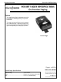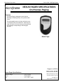
1
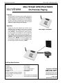
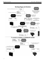
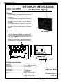
Microframe Corporation
Series 3500:
The MultiPage System
Operating Manual
B3010-7013
*B3010-7013*
SERIES 3500
The MultiPage System
INSTALLATION & SPECIFICATION GUIDE
ITEM NO: B3010-7013
REVISION DATE: 06/09
Microframe Corporation
604 S. 12th Street
Broken Arrow, OK 74012
Tel: (918) 258-4839
Toll Free: 1-800-635-3811
Website: www.microframecorp.com
E-mail: [email protected]
Limited Warranty Agreement
Your Microframe System is warranted
against failure due to defects in workmanship
or material for a period of one (1) year from
the date of purchase. Microframe Corporation
will repair or replace any defective unit. Obvious abuse or mishandling of the unit is NOT
covered by this warranty.
Merchandise Return
If your Unit does not work satisfactorily,
please give us a call. We may be able to solve
the problem by phone. If it becomes necessary to
return your Unit to the factory, please observe
the following:
1. Place Unit in a sturdy box with sufficient
packing material.
2. If requested, include the power adapter.
3. Return the system insured and prepaid
since we are not responsible for shipping damages and losses on returned Units.
Warranty Service
For warranty service, please contact Microframe at 1-800-635-3811. A tech will gladly
assist you.
Assistance
For any product assistance or maintenance
help, contact Microframe by either calling
1-800-635-3811 or emailing us at: support@
microframecorp.com.
Warranty Exclusion
Do not install substitute parts or perform
any modification to the product without first
contacting Microframe.
Microframe Corporation
604 S. 12th Street
Broken Arrow, OK 74012
1-800-635-3811
Warning
All power adapters, line cords, and electrical
equipment should be kept out of the reach of
children and away from water.
Life Support Policy
Microframe's products are not authorized
for use as components in life support devices
or systems without the express written approval of the president of Microframe Corporation. As used herein:
1. Life support devices or systems are defined
as systems which support or sustain life, and
whose failure to perform when properly used in
accordance with instructions for use provided
in the labeling, can be reasonably expected
to result in a significant injury to the user or
anyone depending on the system.
2. A critical component is any component of
a life support device or system whose failure to
perform can be reasonably expected to cause
the failure of the life support device or system,
or to affect its safety or effectiveness.
Disclaimer
We are constantly striving to improve our
products. Due to this, specifications are subject
to change without notice.
Nomenclature
In this manual, use this nomenclature to
distinguish between buttons, functions, messages, and things:
"SEND"
= is a button that is pressed
"ENTER"
= is a button that is pressed
"CANCEL" = is a button that is pressed
send
= a verb used in text
enter
= a verb used in text
"ON"
= turn something "ON" or
"OFF"
= turn something "OFF"
Pager(s)
= noun or object
Display(s) = noun or object
TABLE OF CONTENTS
1 MULTIPAGE SYSTEM OVERVIEW ............................... 6
1.1 MultiPage Transmitter .....................................................6
1.2 Wireless UHF Displays ....................................................6
1.3 Paging Vibrating Pagers ..................................................6
MULTIPAGE SPECIFICATIONS ........................................ 7
2 MULTIPAGE OPERATION .............................................. 9
2.1 Installation........................................................................9
2.2 Operation .........................................................................9
2.3 Configuration ...................................................................9
2.4 Hymn board setup ..........................................................10
UHF DISPLAY SPECIFICATIONS .................................... 11
3 WIRELESS UHF DISPLAY ............................................. 12
3.1 Installation.......................................................................12
3.2 Operation ........................................................................12
3.3 Configuration ..................................................................12
POCKET PAGER SPECIFICATIONS................................ 14
5 POCKET PAGER ............................................................ 15
NEXUS PAGER SPECIFICATIONS .................................. 16
6 NEXUS PAGER .............................................................. 17
SLIMLINE PAGER SPECIFICATIONS .............................. 18
7 SLIMLINE PAGER .......................................................... 19
AFFINITY PAGER SPECIFICATIONS .............................. 20
8 AFFINITY PAGER........................................................... 21
Microframe Corporation
1 MULTIPAGE SYSTEM OVERVIEW
With the MultiPage Transmitter, you can
send numbers to UHF Displays and page
Vibrating Pagers. A MultiPage system is defined as one MultiPage Transmitter and any
combination of these receiver types.
1.1 MULTIPAGE TRANSMITTER
The MultiPage Transmitter is a unique
Transmitter that facilitates the use of UHF
Displays and Pagers. Based on the superb
hardware platform of the Scope DataPage Lite,
the MultiPage is a Microframe software upgrade
designed as the ultimate paging solution.
1.2 WIRELESS UHF DISPLAYS
The new 3500 Series Wireless UHF Displays
have been specifically designed to receive signals from the MultiPage Transmitter. These
Displays come in 2-, 3-, 4- and 6-digit models
with 5.5-inch numbers. They contain the same
high quality construction and components
expected from Microframe's products and
Displays.
Numbers sent to the UHF Display will be
saved and displayed on both the MultiPage and
the UHF Display until deleted. These numbers
can be deleted manually or programmed by the
user to automatically delete, depending on the
user's preference.
1.3 PAGING VIBRATING PAGERS
The MultiPage can be used to send messages to Pagers or to trigger the internal “beep
type”messages of Pocket Pagers. In addition,
the MultiPage Transmitter can re-page Pagers
at user-defined intervals. The list of Pagers
to be re-paged is displayed on the MultiPage
Transmitter screen.
6
Series 3500 - MultiPage System
Microframe Corporation
Series 3500 - MultiPage System
MULTIPAGE SPECIFICATIONS
On-Premise Paging
Features
The MultiPage Transmitter can be used to transmit to
the following receivers: The Wireless UHF Display and
Vibrating Pagers. The MultiPage LCD screen displays
two lists: The first list consists of the numbers being
shown on the UHF Wireless Display. The second list
shows the Pagers waiting to be re-paged.
Operation
Simply plug the power adapter into the back of the
MultiPage and it is ready to use.To enter a number
on the Wireless UHF Display, type the number and
press "ENTER." To send a page to a Vibrating Pager,
type the number of the Pager you wish to page and
press "SEND," then follow the on-screen prompts. To
remove numbers from the Wireless UHF Display, press
"CANCEL," then type the number you want to remove
and then press "ENTER." To remove numbers from
the vibrating re-paging queue, press "CANCEL," then
type the Pager number followed by "SEND."
MultiPage Transmitter
MultiPage Specifications
Dimensions ................................................ 9" x 7.25" x 1.75"
Frequency.................................................. 457.575 MHz
TX Baud Rate ............................................ 512 or 1200
Distance Range ......................................... 1/4 to 1/2 Mile Indoors
FCC Approval No....................................... JRNUSASERILINK
Mounting .................................................... Flat surface
Maximum Numbers shown on Display ...... 20
Maximum Pagers in Re-Page Queue ........ 30
Auto Delete Time ....................................... 0-25 minutes(user-selectable)
Roll Over Time ........................................... 0-9 seconds (user-selectable)
Support and Sales
800-635-3811
Microframe® Corporation
www.microframecorp.com
PO Box 1700
Broken Arrow, OK 74013
7
Microframe Corporation
8
Series 3500 - MultiPage System
Microframe Corporation
Series 3500 - MultiPage System
2 MULTIPAGE OPERATION
2.1 INSTALLATION
The MultiPage Transmitter is designed to set on
a flat surface or table top or installed on a mounting
wedge for an angle or wall mount. To use the Transmitter, simply plug the 12-volt DC power adapter
into the back of the MultiPage and then plug the
adapter into the wall. The MultiPage Transmitter
is now ready for use.
2.2 OPERATION
The MultiPage has two primary operations: One
is to send numbers to Wireless UHF Displays, to page
Vibrating Pagers. The "ENTER" key is associated
with Wireless UHF Display functions. The "SEND"
key is associated with Vibrating Pagers. The following examples explain each of these functions.
2.2.1 Transmitting to UHF Wireless Displays
To send a number to a Display, simply type the
number that you want to display, i.e. “1234” and
then press “ENTER.” To delete a number from the
Display, press “CANCEL,” then type the number, i.e.
“1234” then press “ENTER.”
2.2.2 Transmitting to Vibrating Pagers
To send a page to a Vibrating Pager (i.e. pager
#4), type the pager number “4” then press “SEND."
You will then be prompted for the beep type. Different beep types can display up to three different
factory programmed text messages on the Vibrating
Pager such as:
"COME NOW"
"NEED HELP"
"CHILD FINE"
Type in the desired beep type, or press "ENTER"
to accept the default. Pressing "SEND" from the beep
type screen will page the Pager with a blank message. From the message screen you can type in the
numeric message, i.e. “911” and then press “ENTER”
or “SEND” to send the page to the Vibrating Pager.
If re-page is "ON," you will see the message re-paging on the bottom line of the Transmitters display,
followed by the number of the Vibrating Pager that
you just paged. To stop the re-page of a Vibrating
Pager, press “CANCEL” then type the number of the
Vibrating Pager, i.e. “4” and then press “SEND.”
2.3 CONFIGURATION
The MultiPage Transmitter has several programmable options. To access these options, simply
press the “(“ from the main screen. Then press the
“(“ or “)” brackets to move up or down the list of options. When you come to an option you would like to
change, press “ENTER.” Depending on the option,
you can either press the “(“ and “)” keys to change
the value of the option, or you can use the numbers
to type in the desired value. To return to the main
options menu press “ENTER.” When finished making changes, simply press the "SEND" key to save
the changes or the "CANCEL" key to discard your
changes. Each of the nine option areas are described
in detail below.
Option 1
Transmitter Roll-Over Time
The “Roll-Over” time is the time that each number
in the Transmitter memory shows on the LCD screen
before rotating to the next number. For example,
with the Transmitter Roll-Over Time set to three
seconds, and the Transmitter with “123” and “456”
in its memory, the Transmitter will show “123” for
three seconds and then show “456” for three seconds
and then back to “123.” To change the Transmitter
Roll-Over Time, simply use the “(“ and “)” keys to
select a time from 1 to 16 seconds. When the desired
time is reached press “ENTER.” To place into Hymn
Mode, set the roll-over time to zero (0). See Section
2.4 Hymn Board Setup.
NOTE: The Transmitter Roll-Over Time is completely independent of the UHF Display Roll-Over
Time.
Option 2
Auto Delete Time
The Auto Delete Time is the time that a number
remains on the Display before it is automatically
deleted.This time can be set using the “(“ and “)”
keys to select the desired value from 1 to 25 minutes.
Once the desired value is reached, press “ENTER” to
return to the main systems options menu.
NOTE: The Wireless UHF Display has an independent Auto Delete Time which is set following
the instructions in the UHF Display Section.
The factory default for the UHF Display delete
time is 45 minutes. The reason for having an auto
delete time in the Display, as well as the MultiPage
Transmitter, is best understood by the following
example: At the end of the day, a user may unplug
the Transmitter to turn it off. If there were numbers
being shown on the Display before the power was
unplugged from the Transmitter, the numbers would
remain on the UHF Display until the Display's auto
delete removed them.
9
Microframe Corporation
Option 3
Re-Page Time for Vibrating Pagers
This is the time between re-pages for Vibrating
Pagers. For example, if the re-page time is set to
one minute, then the Vibrating Pagers will be repaged every minute. Using the “(“ and “)” keys you
can choose between 0 and 25 minutes for the repage time. A re-page time of 0 disables re-paging.
When the desired value is selected, press “ENTER”
to return to the main options menu.
Option 4
Set Display ID Address
The options area is used to tell the MultiPage
Transmitter the address of the UHF Display. The
factory default is 1500. If you change this address, you
will also have to set up the UHF Display to respond
to your new address. (See Display Options.)
Option 5
Base ID
The Base ID is the digital identification in which
all components of a system run. The factory default
for this number is 0500000. This number may be
changed to avoid “cross talk” with other nearby
systems. If you change this ID number, then the
UHF Display and Vibrating Pager settings will have
to be changed accordingly. It is recommended that
users do not change this setting.
NOTE: Pager Base ID can only be changed at
the factory.
Option 6
Baud Rate
This is the rate at which the digital communications takes place in your system. It is recommended
that users do not change this setting. If you change
this number, the Display and Vibrating Pager settings will have to be changed accordingly.
NOTE: Pager Baud Rate can only be changed
at the factory.
Option 7
Out-of-Range
This feature is available only with coaster systems. When the out-of-range option is activated,
the transmitter will periodically send a page telling
everyone that they still are in range. If a coaster also
has its out-of-range feature activated, it will sound
an alert within 1 minute of leaving the transmitter’s
coverage area.
Option 8
Behavior
The behavior option exists to accommodate those
users who are more familiar with the DataPage Lite
standard interface and do not need the display or
re-paging capabilities of the MultiPage. The behavior setting can be toggled between “MultiPage”
and “DataPage Lite." In DataPage Lite mode, the
re-page feature is disabled and the Transmitter will
simply wait for a Pager number and then page a
Pager. The screen and button behavior will revert
10
Series 3500 - MultiPage System
to the DataPage Lite operation.
2.4 HYMN BOARD SETUP
To place the MultiPage transmitter into Hymn
Mode, set the roll-over time to zero (0). Note: this
will disable the auto delete and repage functions.
This mode also changes the behavior of the "ENTER"
and "SPACE" buttons when on the main screen. It
is recommended that the roll-over time on the UHF
display also be set to zero (0).
Hymn Mode displays a list of numbers in the
order they are entered. Enter in a list of numbers
to be stored by typing the number and pressing
"ENTER". The first number in the list will show
on the MultiPage screen; the UHF Display will be
unaffected. When ready to show the first number
on the UHF display, press the "ENTER" key. The
MultiPage will send the current number. To delete
the current number and show the next number listed,
simply press the space key. Repeat until all listed
numbers have been displayed.
Microframe Corporation
Series 3500 - MultiPage System
UHF DISPLAY SPECIFICATIONS
On-Premise Paging
Features
The UHF Displays are designed to work best with the
Microframe MultiPage System. The Displays have
two modes:
1) As a "Visual-Pager," the Display will store and rotate
up to 20 numbers at a time. Numbers can be entered
and deleted from the Display using the MultiPage
Transmitter.
2) The Display can also be used as a "Pager Confirmation System." In this mode, the Display shows
the number of every Vibrating Pager that has been
paged.
Operation
UHF Display
Mode 1) Using the MultiPage Transmitter, simply type
in a number and press "ENTER" to send that number
to the Display. To delete a number from the Display,
simply press "CANCEL" then type the number followed by "ENTER."
Mode 2) The number of any Pager that is paged shows
on the Display. No operator intervention is required.
24 Volt AC
9.1"
(23.1 cm)
Model 3500
Wireless
Remote Display
PROGRAM
P.O. Box 1700, Broken Arrow, OK 74013
DATA RECEIVE LED
9.8" 2-DIGIT
(24.9 cm)
13.2" 3-DIGIT
(33.5 cm)
16.8" 4-DIGIT
(42.7 cm)
1.5"
(3.8 cm)
115 TO 24 VAC
WALL MOUNTED
(WIRE-IN)
TRANSFORMER
3010\ax\9700.ai
115 VAC
UHF Display Specifications
Frequency ................................................. 457.575 MHz
TX Baud Rate ............................................ 512 or 1200 auto learning
Distance Range ........................................ 1/4 to 1/2 Miles
Mounting .................................................... Wall Mount or Ceiling Mount
Character Height ....................................... 5.5"
Viewing Distance ....................................... 125 feet indoors
Power Supply ............................................ 16 to 24 VAC
Weight ...................................................... 2-Digit, 2.5 Lbs (1.1 kg)
3-Digit, 3 Lbs (1.4 kg)
4-Digit, 3.5 Lbs (1.6 kg)
6-Digit, 5.25 Lbs (2.4 kg)
Support and Sales
800-635-3811
Microframe® Corporation
www.microframecorp.com
PO Box 1700
Broken Arrow, OK 74013
11
Series 3500 - MultiPage System
Microframe Corporation
3 WIRELESS UHF DISPLAY
3.1 INSTALLATION
Step 1:
Wire in the power adapter. To do this,
simply place one wire from the adapter under
one of the screwdown terminals and the other
wire under the other screwdown terminal as
shown on page 11. At this point, plug in the
power adapter and check the Display for proper
operation.
Step 2:
Hang the Display. The Display is hung on
the wall like a picture frame on a nail or screw.
Simply secure a nail or screw into the wall and
line up the “key hole” in the back of the Display
to hang the Display.
Optional Installation
For aesthetic reasons, you may wish to run
the wire from the power adapter to the Display
concealed in the wall. A person skilled in wiring
should complete this task. The Display uses low
voltage (24-volt) wiring and generally does not
require conduit.
3.2 OPERATION
If you purchased this Display for use with
a MultiPage Transmitter, you should be able
to simply plug in the Display and then enter
and delete numbers as specified in the “MultiPage Operation” section. If you are using
this Display with another transmitter, please
read "Using the Display with the DataPage
Lite or the DataPage II” that's located on the
following page.
3.3 CONFIGURATION
Under normal circumstances, you will not
need to change the Display configuration. The
Display configurations fall into two basic categories. The first is "Display Communication
Settings," and the second is "Display Behavior
Settings."
3.31 Display Communications Settings
The Display comes from the factory ready
to communicate with a MultiPage Transmitter (Base ID 0500000, Baud Rate 512). The
Display will intelligently communicate with
other settings by doing the following:
12
Press the button on the back of the UHF
Display one time. The Display will show vertical
bars. Next, page Pager number 1 with a beep
type of 2 and message 00. The Display should
change to horizontal bars to signify that it has
learned the Transmitter identity (Base ID and
Baud Rate). If the Display does not receive a
valid transmission within 90 seconds, it will
show an EE.
3.32 Display Behavior Settings
The UHF Display's behavior can be changed
by sending special codes to Pager 9999. All codes
are indicated by the form XX_XX or XX_XXXX
where "_" is a space. There are basically five
settings that can be changed using the 9999
command as seen below.
3.33 Mode Settings
The UHF Display has two possible Modes:
Mode 1 displays the messages sent to a specific
Vibrating Pager, and Mode 2 displays all Pager
numbers paged by the Transmitter.
Mode 1) To program the UHF Display to show
all messages sent to Pager 300. Send a page to
Pager 9999 with the message “00_0300.”
NOTE: You must use the “SPACE” key to
insert the space in the message between 00
and the Pager number. The Display will now
show all messages sent to Pager 300.
Mode 2) To program the Display to show all
pages sent by the Transmitter, send a page to
Pager 9999 with the message “00_0000.”
3.331 Roll-Over Time Setting
The Roll-Over Time is the time each number
in the Display memory is shown before changing
to the next number. This time can be set from
1 to 9 seconds. To set this time, send a page to
Pager 9999 with the message “01_0X” where
X is a number 1-9 representing the number of
seconds.
Microframe Corporation
Series 3500 - MultiPage System
3 WIRELESS UHF DISPLAY
3.332 Auto Delete Setting
The Display can be set to automatically
delete a number from its memory after a
preset time. NOTE: If you have a MultiPage
Transmitter, use the Transmitter's auto delete
rather than the Display's auto delete time. To
set the auto delete time send a page to Pager
9999 with the message “02_XX” where XX is a
number from 1 to 42 representing the number
of minutes to wait before auto deleting.
3.333 Chime Setting
If you have purchased an optional triac
circuit, it can be activated every time a new
number is sent to the Display. The duration of
the triac output can be controlled by changing
this option. To change this option, send a page
to 9999 with the message “03_XX” where XX is a
number from 00 to 99 representing the number
of 0.1 second intervals that you want the output
to be on (i.e. 99=9.9 seconds). Sending a 00 will
cause the triac circuit to be disabled.
3.334 Clear All Numbers Command
There are occasions where you may want
to clear all numbers from all Displays. To clear
all numbers, send a page to Pager 9999 with
the message “99_98.”
3.335 Reset Factory Defaults
To change the Display settings back to factory defaults send a page to Pager 9999 with
the message “99_99.”
3.336 Using the UHF Display With A
DataPage Lite or DataPage II
The Wireless UHF Display has been designed to work optimally with the MultiPage
software developed by Microframe Corporation.
However, in rare cases you may want to use
the Display with a Transmitter other than the
MultiPage. If so, you can control the Display's
basic functions by sending pages to the Display’s
address with beep types and messages to control
the function. Beep type “4” enters the number
contained in the message into the Display. Beep
Type “3” removes the number contained in the
message from the Display.
13
Series 3500 - MultiPage System
Microframe Corporation
POCKET PAGER SPECIFICATIONS
On-Premise Paging
Features
The Scope Pocket Pager is designed to work with
the MultiPage or DataPage family of on-premise
transmitters.
The pager can show unlimited numeric messages
sent by the transmitter. Optionally, the pager can
show up to three factory pre-programmed text messages corresponding to the beep type specified.
Pocket Pager
Support and Sales
Pocket Pager Specifications
Distance Range .........................................1/4 to 1/2 mile
Power ........................................................Requires one AAA battery (included)
Size............................................................2.5 x 1.5 (1.75 with holster)
14
800-635-3811
Microframe® Corporation
www.microframecorp.com
PO Box 1700
Broken Arrow, OK 74013
Microframe Corporation
Series 3500 - MultiPage System
5 POCKET PAGER
5.1 TURNING ON THE PAGER
Hold down the LARGE GRAY BUTTON
until the Pager comes on.
5.2 SENDING A PAGE
Please see the diagram in the MultiPage
section of this manual for detailed instructions
on sending pages.
5.3 ACTIVATING AN ALPHA MESSAGE
To activate a pre-defined message to a Vibrating Pager, type in the Pager number followed
by the "SEND" key. You will be prompted for
a “BEEP TYPE (1-4).” Select 1-3 here and
press the “SEND” key. This will display on the
Pager one of the three pre-programmed text
messages stored in the Pager. If no number is
chosen, the Pager will default to Beep Type 4
(“PAGING”).
5.4 SENDING A NUMERIC MESSAGE
To send a numeric message to a Pager,
simply type in the Pager number followed by
the “SEND” key. The Transmitter screen will
display “BEEP TYPE.” Simply press “ENTER”
to bypass this. The Transmitter screen will
then display “ENTER MESSAGE.” Using the
number keys, type in a numeric message up to
16 digits followed by the “SEND” key. Note:
If the message portion of a page is not blank
the “BEEP TYPE” alpha message selected will
be ignored.
5.5 RECEIVING A PAGE
The Pocket Pager will start to vibrate
when it is paged. No action is necessary on
the receiving end. The Pager will stop vibrating after approximately eight seconds. If the
user would like to stop the vibration before
the eight seconds, simply press the LARGE
GRAY BUTTON. If a numeric message is sent
to the Pager, the message will be visible on
the Pager's LCD screen until the Pager stops
vibrating. To view the message after the Pager
has stopped vibrating, press the LARGE GRAY
BUTTON once.
5.6 SENDING A GROUP CALL PAGE
chosen by the customer and programmed at
the factory). To page all Pagers at once, simply
enter “900” and "SEND." Then press "SEND"
again at the beep type prompt.
5.7 MANUAL PAGER TURN-OFF
Press the DOWN ARROW BUTTON four
times. The words “PGR OFF” will appear
on the LCD screen. Press the LARGE GRAY
BUTTON once to confirm. NOTE: If you have
chosen to order the Pagers with the on/off button disabled, then Pagers can only be turned
off from the Transmitter.
5.8 PAGER TURN-OFF FROM BASE
Enter the pager number followed by the
“SEND” key.
Press “ENTER” to bypass “BEEP TYPE”
screen. When screen reads “ENTER MESSAGE,” enter the message code “(0091)(0)” followed by “SEND.” NOTE: In order for the code
to work, the parentheses must be entered.
Since all Pagers respond to call number
“900,” paging “900” with the message code
“(0091)(0)” will turn all Pagers off.
5.9 POWER CHECKING
When the battery level is low, a low-battery
symbol will appear at the bottom of the Pager
screen.
5.10 LIGHTING FUNCTION
Pressing the UP ARROW BUTTON for two
seconds will turn on the backlight on the LCD
screen. The light will shut off automatically
after approximately 10 seconds, or the user
may turn the light off manually by pressing
the UP ARROW BUTTON once.
5.11 CAUTION
a)
b)
c)
The Pager is made up of LCD and
precision elements. Avoid water and
high temperature.
Remove the battery if the Pager will
not
be in use for a long period of time.
If the Pager is not working properly,
do not dismantle or repair it yourself.
Call Microframe for technical service.
All Pagers respond to call number “900”
(unless another group call number has been
15
Series 3500 - MultiPage System
Microframe Corporation
NEXUS PAGER SPECIFICATIONS
On-Premise Paging
Features
The Nexus Pager is designed to work with the
MultiPage or DataPage family of on-premise transmitters.
The rechargeable pager can show unlimited numeric messages sent by the transmitter. Optionally, the
pager can show up to three factory pre-programmed
text messages corresponding to the beep type
specified.
Nexus Pager
Support and Sales
Nexus Pager Specifications
Distance Range .........................................1/4 to 1/2 mile
Power ........................................................Rechargeable
Size............................................................3.5" x 2.25" x .6875"
16
800-635-3811
Microframe® Corporation
www.microframecorp.com
PO Box 1700
Broken Arrow, OK 74013
Microframe Corporation
Series 3500 - MultiPage System
6 NEXUS PAGER
6.1 TURNING ON THE PAGER
Hold down the RED BUTTON on the side
until the pager comes on.
6.2 SENDING A PAGE
Please see the diagram in the MultiPage
section of this manual for detailed instructions
on sending pages.
6.3 ACTIVATING AN ALPHA MESSAGE
To activate a pre-defined message to a Vibrating Pager, type in the Pager number followed
by the "SEND" key. You will be prompted for
a “BEEP TYPE (1-4).” Select 1-3 here and
press the “SEND” key. This will display on the
Pager one of the three pre-programmed text
messages stored in the Pager. If no number is
chosen, the Pager will default to Beep Type 4
(“PAGING”).
6.4 SENDING A NUMERIC MESSAGE
To send a numeric message to a Pager,
simply type in the Pager number followed by
the “SEND” key. The Transmitter screen will
display “BEEP TYPE.” Simply press “ENTER”
to bypass this. The Transmitter screen will
then display “ENTER MESSAGE.” Using the
number keys, type in a numeric message up to
16 digits followed by the “SEND” key. Note:
If the message portion of a page is not blank
the “BEEP TYPE” alpha message selected will
be ignored.
6.5 RECEIVING A PAGE
The Pager will start to vibrate when it is
paged. No action is necessary on the receiving
end. The Pager will stop vibrating after approximately eight seconds. If the user would like
to stop the vibration before the eight seconds,
simply press the RED BUTTON on the side of
the pager. If a numeric message is sent to the
Pager, the message will be visible on the Pager's
LCD screen until the pager stops vibrating. To
view the message and turn off flashing lights,
press the RED BUTTON three times.
6.6 SENDING A GROUP CALL PAGE
the factory). To page all pagers at once, simply
enter “900” and "SEND." Then press "SEND"
again at the beep type prompt.
6.7 MANUAL PAGER TURN-OFF
Press the RED BUTTON on the side of
the pager for 5 seconds or place pager on the
charging base.
6.8 LIGHTING FUNCTION
Press the RED BUTTON on the side of
pager.
6.9 CHANGING THE ALERT MODE
Pagers may be programmed to respond to a
page by flashing lights, flashing and beeping,
flashing and vibrating, or flashing, vibrating
and beeping. By default, the pagers are programmed to flash and vibrate for 8 seconds.
To change the alert mode, follow these
instructions: Remove all the pagers from the
charging unit or unplug the power supply that
is connected to the charging base. Wait for the
demo page to stop (about 7 seconds). Press
"1248" followed by "SEND" and "ENTER." For
the message, enter the code that corresponds
to the alert that you want. (See below.) For
example, if you want the pagers to Flash only,
press "1248-SEND-ENTER-9797-SEND." After
sending the code, the lights on all the pagers
will flash to indicate the programming was
received. Return all the pagers to the charging base or plug the power supply back in. The
pagers are ready to receive the page with the
new alert.
Flash & Beep
Flash & Vibrate
Flash Only
Flash, Vibrate & Beep
"9595"
"9696"
"9797"
"9898"
6.10 CAUTION
a)
b)
The pager is made up of LCD and
precision elements. Avoid water and
high temperature.
If the pager is not working properly,
do not dismantle or repair it yourself.
Call Microframe for technical service.
All pagers respond to call number “900”
(unless another group call number has been
chosen by the customer and programmed at
17
Series 3500 - MultiPage System
Microframe Corporation
SLIMLINE PAGER SPECIFICATIONS
On-Premise Paging
Features
The SlimLine Pager is designed to work with the
MultiPage or DataPage family of on-premise transmitters.
The rechargeable pager has vibrate only and LED
alert capability.
SlimLine Pager
Support and Sales
SlimLine Pager Specifications
Distance Range .........................................1/4 to 1/2 mile
Power ........................................................Rechargeable
Size............................................................5" x 2.125" x .625"
18
800-635-3811
Microframe® Corporation
www.microframecorp.com
PO Box 1700
Broken Arrow, OK 74013
Microframe Corporation
Series 3500 - MultiPage System
7 SLIMLINE PAGER
7.1 SENDING A PAGE
Please see the diagram in the MultiPage
section of this manual for detailed instructions
on sending pages.
7.2 SENDING A GROUP CALL PAGE
All pagers respond to call number “900”
(unless another group call number has been
chosen by the customer and programmed at
the factory). To page all pagers at once, simply
enter “900” and "SEND." Then press "SEND"
again at the beep type prompt.
7.3 CHANGING THE ALERT MODE
Pagers may be programmed to respond to
a page by vibrating, flashing lights, flashing
and vibrating. By default, the pagers are programmed to flash and vibrate for 3 minutes.
To change the alert mode, follow these
instructions: Remove all the pagers from the
charging unit or unplug the power supply that
is connected to the charging base. Wait for the
demo page to stop (about 7 seconds). Press
"1248" followed by "SEND" and "ENTER." For
the message, enter the code that corresponds
to the alert that you want. (See below.) For
example, if you want the pagers to Flash only,
press "1248-SEND-ENTER-9797-SEND." After
sending the code, the lights on all the pagers
will flash to indicate the programming was
received. Return all the pagers to the charging base or plug the power supply back in. The
pagers are ready to receive the page with the
new alert.
Vibrate Only
Flash & Vibrate
Flash Only
"9292"
"9696"
"9797"
19
Series 3500 - MultiPage System
Microframe Corporation
AFFINITY PAGER SPECIFICATIONS
On-Premise Paging
Features
The Affinity Pager is designed to work with the MultiPage or DataPage family of on-premise transmitters.
The rechargeable vibrating pager has illuminating
lights, vibrate and tone alert options for personalization.
Affinity Pager
Support and Sales
Affinity Pager Specifications
Distance Range .........................................1/4 to 1/2 mile
Power ........................................................Rechargeable
Size............................................................3" x 2.25" x .6875"
20
800-635-3811
Microframe® Corporation
www.microframecorp.com
PO Box 1700
Broken Arrow, OK 74013
Microframe Corporation
Series 3500 - MultiPage System
8 AFFINITY PAGER
8.1 SENDING A PAGE
Please see the diagram in the MultiPage
section of this manual for detailed instructions
on sending pages.
8.2 SENDING A GROUP CALL PAGE
All pagers respond to call number “900”
(unless another group call number has been
chosen by the customer and programmed at
the factory). To page all pagers at once, simply
enter “900” and "SEND." Then press "SEND"
again at the beep type prompt.
8.4 CHANGING THE ALERT MODE
Pagers may be programmed to respond to
a page by vibrating, flashing lights, flashing
and beeping, flashing and vibrating, or flashing, vibrating and beeping. By default, the
pagers are programmed to flash and vibrate
for 8 seconds.
To change the alert mode, follow these
instructions: Remove all the pagers from the
charging unit or unplug the power supply that
is connected to the charging base. Wait for the
demo page to stop (about 7 seconds). Press
"1248" followed by "SEND" and "ENTER." For
the message, enter the code that corresponds
to the alert that you want. (See below.) For
example, if you want the pagers to Flash only,
press "1248-SEND-ENTER-9797-SEND." After
sending the code, the lights on all the pagers
will flash to indicate the programming was
received. Return all the pagers to the charging base or plug the power supply back in. The
pagers are ready to receive the page with the
new alert.
Vibrate Only
Flash & Beep
Flash & Vibrate
Flash Only
Flash, Vibrate & Beep
"9292"
"9595"
"9696"
"9797"
"9898"
21
Series 3500 - MultiPage System
Microframe Corporation
Microframe Corporation
604 S. 12th Street
Broken Arrow, OK 74012
Tel: (918) 258-4839
Toll Free: 1-800-635-3811
Website: www.microframecorp.com
E-mail: [email protected]
22