1
A
D
B
C
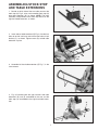
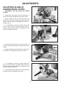
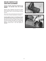
Fig. 37
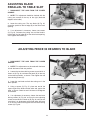
Fig. 38
1. Move the table to the 31-5/8 degree right miter position and lock the table in position. NOTE:
A triangle indicator is provided on the miter scale to find this angle quickly.
2. Tilt the saw blade to the 33-7/8 degree left bevel position and tighten bevel lock handle. NOTE:
A triangle indicator is provided on the bevel scale to find this angle quickly.
3. Place the crown moulding on the table with the CEILING EDGE of the moulding against the
fence, and make the cut, as shown in Fig. 37. NOTE: The piece of crown moulding used for the
outside corner will always be on the right hand side of the blade, as shown at (A) Fig. 37. The piece
of crown moulding used for the inside corner will always be on the left hand side of the blade, as
shown at (B) Fig. 37.
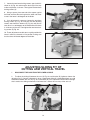
4. To make the matching halves of the inside and outside corners simply rotate the table to the
31-5/8 degree left miter position and tighten table lock knob. NOTE: A triangle indicator is provided on the miter scale to find this angle quickly.
5. Place the crown moulding on the table with the WALL EDGE of the crown moulding against
the fence and make the cut. Again, the piece of crown moulding used for the outside corner will
always be on the right side of the blade, as shown at (C) Fig. 38. The piece of crown moulding
used for the inside corner will always be on the left side of the blade, as shown at (D) Fig. 38.
AUXILIARY WOOD FENCE
When performing multiple or repetitive cut-off operations
that result in small cut-off pieces, one inch or less, it is
possible for the saw blade to catch the cut-off pieces and
project them out of the machine or into the blade guard
and housing, possibly causing damage or injury. In order
to limit the possibility of personal injury or blade guard
damage, an auxiliary wood fence can be mounted to your
saw as follows:
A
A
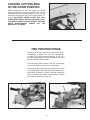
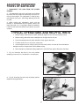
Holes are provided in the fence to attach an auxiliary
fence (A) Fig. 39. This auxiliary fence is constructed of
straight wood approximately 1/2 inch thick by 3 inches
high
by
20 inches long. NOTE: The auxiliary fence (A) is used
ONLY with the saw blade in the 0 degree bevel position
(90 degrees to the table). When bevel cutting (blade tilted) the auxiliary fence will have to be removed.
Fig. 39
17