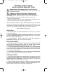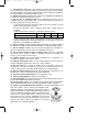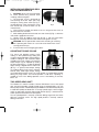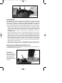
1
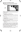
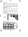
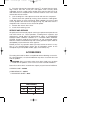
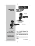
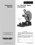
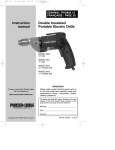
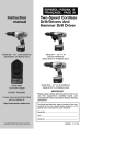
900470 - 11-30-00.QXD
9/25/02
11:09 AM
Page 1
ESPAÑOL: PÁGINA 17
FRANÇAISE : PAGE 35
Instruction
manual
Two-Speed Cordless
Hammer Drill/Drivers
MODELS
8604 and 8624
Chargers
MODEL 877
Hammer Drill/Driver
MODEL 8723
Battery Pack
MODEL 887
Hammer Drill/Driver
MODEL 8823
Battery Pack
To learn more about Porter-Cable
visit our website at:
http://www.porter-cable.com
IMPORTANT
Please make certain that the person who is
to use this equipment carefully reads and
understands these instructions before
starting operations.
The Model and Serial No. plate is located on the main
housing of the tool. Record these numbers in the
spaces below and retain for future reference.
Model No. ______________________________________
Type ___________________________________________
Serial No. _______________________________________
Copyright © 2000 Porter-Cable Corporation
Part No. 900470-0011
900470 - 11-30-00.QXD
9/25/02
11:09 AM
Page 2
GENERAL SAFETY RULES
FOR ALL BATTERY OPERATED TOOLS
WARNING! READ AND UNDERSTAND ALL INSTRUCTIONS.
Failure to follow all instructions listed below, may result in electric shock, fire
and/or serious personal injury.
WARNING: SOME DUST CREATED BY POWER SANDING,
SAWING, GRINDING, DRILLING, AND OTHER CONSTRUCTION
ACTIVITIES contains chemicals known to cause cancer, birth defects or
other reproductive harm. Some examples of these chemicals are:
· lead from lead-based paints,
· crystalline silica from bricks and cement and other masonry products, and
· arsenic and chromium from chemically-treated lumber.
Your risk from these exposures varies, depending on how often you do this
type of work. To reduce your exposure to these chemicals: work in a well
ventilated area, and work with approved safety equipment, such as those dust
masks that are specially designed to filter out microscopic particles.
SAVE THESE INSTRUCTIONS.
WORK AREA
1. Keep your work area clean and well lit. Cluttered benches and dark
areas invite accidents.
2. Do not operate power tools in explosive atmospheres, such as in the
presence of flammable liquids, gases, or dust. Power tools create sparks
which may ignite the dust or fumes.
3. Keep bystanders, children, and visitors away while operating a
power tool. Distractions can cause you to lose control.
ELECTRICAL SAFETY
1. Do not abuse the cord. Never use the cord to carry the tool. Keep
cord away from heat, oil, sharp edges, or moving parts. Replace
damaged cords immediately. Damaged cords may create a fire.
2. A battery operated tool with integral batteries or a separate battery
pack must be recharged only with the specified charger for the battery.
A charger that may be suitable for one type of battery may create a risk of fire
when used with another battery.
3. Use battery operated tool only with specifically designated battery
pack. Use of any other batteries may create a risk of fire.
PERSONAL SAFETY
1. Stay alert, watch what you are doing, and use common sense when
operating a power tool. Do not use tool while tired or under the influence
of drugs, alcohol, or medication. A moment of inattention while operating
power tools may result in serious personal injury.
2. Dress properly. Do not wear loose clothing or jewelry. Contain long
hair. Keep your hair, clothing, and gloves away from moving parts. Loose
clothes, jewelry, or long hair can be caught in moving parts.
2
900470 - 11-30-00.QXD
9/25/02
11:09 AM
Page 3
3. Avoid accidental starting. Be sure switch is in the locked or off
position before inserting battery pack. Carrying tools with your finger on the
switch or inserting the battery pack into a tool with the switch on invites
accidents.
4. Remove adjusting keys or wrenches before turning the tool on. A
wrench or a key that is left attached to a rotating part of the tool may result in
personal injury.
5. Do not overreach. Keep proper footing and balance at all times.
Proper footing and balance enable better control of the tool in unexpected
situations.
6. Use safety equipment. Always wear eye protection. Dust mask, nonskid safety shoes, hard hat, or hearing protection must be used for
appropriate conditions.
TOOL USE AND CARE
1. Use clamps or other practical way to secure and support the
workpiece to a stable platform. Holding the work by hand or against your
body is unstable and may lead to loss of control.
2. Do not force tool. Use the correct tool for your application. The
correct tool will do the job better and safer at the rate for which it is designed.
3. Do not use tool if switch does not turn it on or off. A tool that cannot
be controlled with the switch is dangerous and must be repaired.
4. Disconnect battery pack from tool or place the switch in the locked
or OFF position before making any adjustments, changing accessories,
or storing the tool. Such preventive safety measures reduce the risk of
starting the tool accidentally.
5. Store idle tools out of reach of children and other untrained persons.
Tools are dangerous in the hands of untrained users.
6. When battery pack is not in use, keep it away from other metal
objects like: paper clips, coins, keys, nails, screws, or other small metal
objects that can make a connection from one terminal to another.
Shorting the battery terminals together may cause sparks, burns, or a fire.
7. Maintain tools with care. Keep cutting tools sharp and clean. Properly
maintained tools with sharp cutting edge are less likely to bind and are easier
to control.
8. Check for misalignment or binding of moving parts, breakage of
parts, and any other condition that may affect the tool’s operation. If
damaged, have the tool serviced before using. Many accidents are caused
by poorly maintained tools.
9. Use only accessories that are recommended by the manufacturer for
your model. Accessories that may be suitable for one tool may create a risk
of injury when used on another tool.
SERVICE
1. Tool service must be performed only by qualified repair personnel.
Service or maintenance performed by unqualified personnel may result in a
risk of injury.
2. When servicing a tool, use only identical replacement parts. Follow
instructions in the Maintenance Section of this manual. Use of
unauthorized parts or failure to follow Maintenance Instructions may create a
risk of shock or injury.
3
900470 - 11-30-00.QXD
9/25/02
11:09 AM
Page 4
SPECIFIC SAFETY RULES AND SYMBOLS
1. Hold tool by insulated gripping surfaces when performing an operation
where the cutting tool may contact hidden wiring. Contact with a “live” wire
will also make exposed metal parts of the tool “live” and shock the operator.
2. There are certain applications for which this tool was designed.
Porter-Cable strongly recommends that this tool NOT be modified and/or
used for any application other than for which it was designed. If you have any
questions relative to its application DO NOT use the tool until you have written
Porter-Cable and we have advised you.
Technical Service Manager
Porter-Cable Corporation
4825 Highway 45 North
Jackson, TN 38305
3. Be aware that this tool is always in an operating condition, because it
does not have to be plugged into an electrical outlet. Always set the trigger
siwtch to the locked OFF position when installing or removing the battery pack
or drill bits.
4. Do not use bits larger than those recommended (see Maximum
Capacities Chart). Large bits may overload the drill and damage the motor and
gears.
5. Do not use if chuck jaws or other parts are cracked or worn.
6. Verify the drill’s rotation before starting the drill so it is correct for the
operation being performed.
7. Never change direction of rotation until motor has completely stopped.
8. Never hold work in your hand, lap, or against other parts of your body
when drilling.
9. Do not use drill as a router or try to elongate or enlarge holes by twisting
the drill. Drill bits may break and cause injury.
10. Keep hands away from rotating parts.
11. Keep drill bit clear of yourself and all objects while installing and
removing bits (see INSTALLING AND REMOVING BITS).
12. Some wood contains preservatives which can be toxic. Take extra care
to prevent inhalation and skin contact when working with these materials.
Request, and follow, all safety information available from your material supplier.
SYMBOL
V
..........................
____
..........................
–––
..........................
no
…/min ..........................
DEFINITION
volts
direct current
no load speed
revolutions or reciprocation per minute
SAFETY INSTRUCTIONS FOR CHARGER AND BATTERIES
1. Save these instructions. This manual contains important safety and
operating instructions for tool batteries and battery chargers.
2. Before using a battery charger, read all instructions and cautionary
markings on (1) battery charger, (2) battery pack, and (3) product using battery.
3. CAUTION: To reduce risk of injury, Porter-Cable charger Model 8604
should only be used to charge Porter-Cable battery pack Model 8723 and
Porter-Cable charger Model 8624 should only be used to charge Porter-Cable
battery pack Model 8823. Other types of batteries may burst causing personal
injury and damage. Do not charge Porter-Cable Models 8723 and 8823
battery packs with any other chargers.
4. Do not expose charger to rain, snow or frost.
4
900470 - 11-30-00.QXD
9/25/02
11:09 AM
Page 5
5. Do not abuse cord. Never carry charger by cord or yank it to disconnect
from receptacle. Pull by plug rather than cord when disconnecting charger.
Have damaged or worn power cord and strain reliever replaced immediately.
DO NOT ATTEMPT TO REPAIR POWER CORD.
6. Make sure cord is located so that it will not be stepped on, tripped over,
or otherwise subjected to damage or stress.
7. Do not use an extension cord unless absolutely necessary. Use of
improper extension cord could result in a risk of fire and electric shock. If an
extension cord must be used, make sure:
A. That the pins on plug of extension cord are the same number, size and
shape as those of plug on charger.
B. That the extension cord is properly wired and in good electrical
condition.
C. Wire Size of cord is at least as specified in following chart:
LENGTH OF CORD IN FEET
25
50
100
150
AWG SIZE OF CORD
18
18
18
16
D. If an extension cord is to be used outdoors it must be marked with the
suffix W-A following the cord type designation. For example – SJTW-A to
indicate it is acceptable for outdoor use.
8. Do not operate charger with damaged cord or plug – have them replaced
immediately, to avoid a hazard. DO NOT ATTEMPT TO REPAIR POWER CORD.
9. Do not operate charger if it has received a sharp blow, been dropped, or
otherwise damaged in any way; take it to a qualified serviceman.
10. Do not dissassemble charger or battery pack. Take it to a qualified
serviceman when service or repair is required. Incorrect reassembly may
result in a risk of electric shock or fire.
11. Unplug charger from outlet before attempting any maintenance or
cleaning – to reduce risk of electric shock.
12. Charge the battery pack in a well ventilated place, do not cover the
charger and battery pack with a cloth, etc., while charging.
13. Do not store the charger or battery pack in locations where the
temperature may reach or exceed 122°F (such as a metal tool shed, or a car
in the summer), which can lead to deterioration of the storage battery.
14. Do not charge battery pack when the temperature is BELOW 32°F or
ABOVE 104°F. This is very important for proper operation.
15. Do not incinerate battery pack. It can explode in a fire.
16. Do not charge battery in damp or wet locations.
17. Do not attempt to charge any other cordless tool or battery pack with the
Porter-Cable Model 8604 or 8624 chargers.
18. Do not short across the terminals of the battery pack: EXTREMELY
HIGH TEMPERATURES COULD CAUSE PERSONAL INJURY OR FIRE.
19. Dispose of expended batteries properly. The Porter-Cable Models 8723
and 8823 Battery Packs contain rechargeable nickelcadmium batteries. These batteries must be recycled or
disposed of properly. Drop off expended battery packs at
your local replacement battery retailer, your local recycling
center, or at a Porter-Cable Service Center (see list on
back page of this manual). Applicable fees for the
collection and recycling of these batteries (in the United
States), have been paid to the RBRC™. For further RBRC™ is a Trademark of
the Rechargeable Battery
information, call: 1-800-8-BATTERY.
Recyling Corporation.
5
900470 - 11-30-00.QXD
9/25/02
11:09 AM
Page 6
ADDITIONAL SAFETY RULES FOR HAMMER-DRILLS
1. Apply forward force only on pistol grip handle and ONLY with your
hands when drilling.
2. Do not use bits larger than those recommended. They may cause
personal injury due to jamming and loss of control. Large bits may also
overload the drill and damage the motor and gears.
3. Verify that the mode selecting ring, the speed selector, and the reversing
switch are in correct positions for the operation being performed.
4. Use only percussion-type carbide-tipped bits when hammer-drilling.
5. Always wear ear protectors and safety glasses when hammer-drilling.
6. Do not attempt to cut through reinforcing rods with percussion-type bits.
7. Should the drill bit become jammed in the work, release switch trigger
immediately to prevent personal injury. Remove the battery from the tool and
remove the drill bit from the work. Do not attempt to free the stalled bit by
starting and stopping the motor. This could result in bodily injury.
FUNCTIONAL DESCRIPTION
FOREWORD
Your Porter-Cable Cordless Hammer Drill/Driver is designed to drill holes and
drive fasteners in various materials as indicated in the following chart:
SPEED
RANGE
LOW
HIGH
MAXIMUM CAPACITIES
DRILLING
MILD STEEL ALUMINUM WOOD SELF-FEED BIT
3/8"
3/8"
1"
3/8"
3/8"
1/2"
DRIVING
WOOD SCREWS
3/8"
#10
SWITCH OPERATION
Squeeze trigger switch (A) Fig. 1, to
start motor. Release trigger to stop
motor. As the trigger is squeezed the
motor speed increases.
NOTE: A low volume, high
pitched tone may be heard while
the switch is in the variable
speed mode. This is normal.
B
A
Fig. 1
FORWARD/REVERSE
• Make sure trigger switch (A) Fig. 1, is in OFF position before attempting to
change direction of rotation.
• Push button (B) Fig. 1, toward left side of drill for FORWARD (clockwise)
rotation.
• Push button (B) Fig. 1, toward right side of drill for REVERSE (counterclockwise) rotation.
• Place button (B) Fig. 1, in center position to lock trigger switch in OFF
position.
ELECTRIC BRAKE
When the trigger switch is released, an electric brake automatically engages
to stop spindle rotation.
6
900470 - 11-30-00.QXD
9/25/02
11:09 AM
Page 7
INSTALLING AND REMOVING DRILL
AND SCREWDRIVER BITS
1. CAUTION: Always set reversing button
to center (locked OFF) position when
installing and removing bits.
2. The three-jaw chuck is designed for
self-centering of the bit. Open jaws large
A
B
enough by turning outer sleeve (A) Fig. 2,
counterclockwise, when viewing the chuck
Fig. 2
from the bit end, so that bit shank can be
inserted easily.
3. Clean and insert smooth end of bit as far as it will go into the chuck, or
up to the flutes for small bits.
4. While holding the bit with one hand, turn outer sleeve (A) Fig. 2, clockwise
until the bit is gripped in the chuck.
5. Tighten chuck by holding chuck ring (B) Fig. 2, with one hand while
turning outer sleeve (A) clockwise with other hand. Tighten securely.
WARNING: Do not operate drill motor while installing or removing
bits. Operating drill motor can cause bit to be thrown from chuck
causing personal injury.
6. To remove bit, reverse foregoing procedure.
ADJUSTING TORQUE COLLAR
The clutch unit provides twenty clutch
settings, a “Drill” (solid lock-up) setting, and
A
a hammer (impact) position. Lowest torque is
avaible at setting #1, with maximum torque
available at the “Drill” setting. The amount of
output torque may be adjusted by rotating
B
the front collar (A) Fig. 3, so that the desired
torque setting is aligned with the index mark
(B) Fig. 3. In general, lower torque settings
are used for driving small screws and other
Fig. 3
delicate work, while higher torque settings
are used for driving larger screws. The “Drill” position is used for drilling and for
driving very large screws. The hammer position is used when “impacting” is
needed to assist in the drilling operation such as when drilling in concrete,
bricks, etc.
TWO-SPEED GEAR SHIFT
The Models 877 and 887 Cordless Hammer Drill/Drivers have a two-speed
gear shift which provides spindle speed ranges of approximately: 0 to 475
RPM (LOW) and 0 to 1450 RPM (HIGH) for Model 877; 0-500 RPM (LOW) and
0-1500 RPM (HIGH) for Model 887. To change speed ranges: release trigger
switch to stop motor and then slide speed selector (A) Fig. 4, toward rear for
HIGH speed or toward front for LOW speed.
The low speed position is normally used when drilling larger holes and when
driving or removing screws. The high speed position is normally used for
drilling small holes.
7
900470 - 11-30-00.QXD
9/25/02
11:09 AM
Page 8
DRIVER BIT STORAGE
Convenient storage areas with retaining clip
(B) Fig. 4, for screwdriver bits are provided
on each side of the tool.
A
B
Fig. 4
OPERATION
CHARGING THE BATTERY PACK GENERAL
Before using your cordless tool for the first time, the battery pack should be
fully charged. If the battery pack is installed in the tool, remove it by following
instructions under INSTALLING OR REMOVING BATTERY PACK.
As a battery pack approaches the discharged state, you will notice a sharp
drop in tool performance. When the tool is unable to perform the task at hand,
it is time to recharge the battery pack. Recharging the battery pack before this
condition is reached will reduce the total work life of the pack. Discharging the
pack beyond this point can damage the pack.
NOTE: Battery temperature will increase during and shortly after use.
Batteries may not accept a full charge if they are charged immediately
after use. Allow the battery pack to cool to room temperature before
charging for best results.
The battery charger may rest on the four pads provided on the bottom of the
case or be mounted on a wall by utilizing the two key hole slots provided.
CAUTION: Vent slots in top and bottom of charger must not be
obstructed. Do not charge battery when temperature is BELOW 32°F
or ABOVE 104°F.
NORMAL CHARGING
Make sure power circuit voltage is the same as that shown on the charger
specification plate. Connect charger to power source. The green light (A) Fig.
5, should begin to flash. This indicates the charger is ready to begin charging.
Position battery pack on charger, align rails (A) Fig. 6 on battery pack with four
tabs (A) Fig. 5 on charger. Slide battery forward onto charger until it stops.
The green light (A) Fig. 5, should begin to glow continuously, indicating that
the battery pack is receiving a “Fast Charge” (if the green light does not glow
continuously, or if the red light (B) Fig. 5, also begins to flash: see
DIAGNOSTICS). After approximately one hour, the “Fast Charge” indicator
light should go out indicating that the battery pack is fully charged and that
the charger is now in a “Trickle Charge” mode. The battery pack can be left
on “Trickle Charge” until you are ready to use it.
Depending on room temperature, line voltage, and existing charge level, initial
battery charging may take longer than one hour.
Disconnect charger from power source when not in use.
8
900470 - 11-30-00.QXD
9/25/02
11:09 AM
A B
Page 9
C
Fig. 5
DIAGNOSTICS
The Models 8604 and 8624 chargers are equipped with a diagnostic system
that automatically checks the battery pack each time a pack is inserted into
the charger. If no problems are found, the charger will automatically switch to
“Fast Charge” mode as described in NORMAL CHARGING. If a problem is
found, it will be indicated by the charger indicator lights (see Fig. 5), as follows:
• Green light (A) continues to flash after battery pack is inserted in charger:
indicates that the battery pack temperature is either too high or too low for
charging. If left alone, the charger will continue to monitor the battery pack
temperature and will begin charging when the temperature reaches an
acceptable level.
• Green light (A) glows continuously and red light (B) flashes: indicates that the
battery pack is receiving a “Fast Charge”, but the battery pack voltage is
low. It is not unusual for a new, or a fully discharged battery pack to give this
indication for the first several minutes of charge. If the red light continues to
flash throughout the charge cycle, it indicates that the pack is weak and will
provide reduced performance (the pack is still useable, but will not provide
maximum power or work per charge). This battery pack will probably require
replacement in the near future.
• Green light (A) continues to flash and red light (B) flashes: indicates that the
battery pack has failed (pack is not chargeable and requires replacement).
INSTALLING OR REMOVING BATTERY PACK
TO REMOVE BATTERY PACK: Depress the battery release button (B) Fig. 6,
and pull battery pack out of tool.
TO INSTALL
BATTERY PACK:
Align rails (A) Fig. 6,
on battery pack with
slots on tool and
push battery pack
onto tool until it locks
in place.
B
A
Fig. 6
9
900470 - 11-30-00.QXD
9/25/02
11:09 AM
Page 10
HOW TO HOLD THE HAMMER DRILL/DRIVER
WARNING: The front end of the Hammer Drill/Driver may be made
live if the tool drills into live wiring in the wall. TO PREVENT
ELECTRICAL SHOCK, THE HAMMER DRILL/DRIVER MUST BE
HELD AS SHOWN IN FIG. 7.
IT’S
A DRILL
Fig. 7
GENERAL DRILLING
1. Set torque adjusting collar for drilling operation and set speed selector to
appropriate speed.
2. Be sure drill bit is securely gripped in chuck.
3. Set REVERSING BUTTON for clockwise rotation.
4. CAUTION: Make sure work is held securely in vise or clamped in place
prior to starting drilling operation. Loose work may spin and cause bodily
injury.
5. Locate exact center for hole to be drilled and using a center punch, make
a small dent in work.
6. Place tip of drill bit in dent made by center punch, hold drill square with
work, and start the motor.
7. CAUTION: Applying too much pressure may cause the bit to overheat or
break resulting in bodily injury or damaged drill bits.
Apply steady, even pressure to keep drill bit cutting. Too little pressure will
keep the bit from cutting and dull the cutting edges due to excessive friction
created by sliding over the surface.
CAUTION: Always be alert and brace yourself against the twisting
action of the drill.
8. If drill stalls or becomes jammed in the hole, release trigger immediately,
remove drill bit from work and determine cause of stalling or jamming. DO
NOT SQUEEZE TRIGGER ON AND OFF IN AN ATTEMPT TO FREE A
STALLED OR JAMMED DRILL – THIS WILL DAMAGE THE MOTOR. The
direction of rotation may be reversed to help free a jammed bit. Be sure
direction of rotation is RESET before attempting to continue drilling.
9. Reduce the pressure on the drill just before the bit cuts through the work
to avoid splintering wood or stalling in metal.
10. When bit has completely penetrated work and is spinning freely, withdraw
it from the work while the motor is still running, then turn off drill.
10
900470 - 11-30-00.QXD
9/25/02
11:10 AM
Page 11
DRILLING WOOD
In addition to the instructions listed under GENERAL DRlLLlNG, the following
also apply:
1. When using twist drills in wood, they should be withdrawn from the hole
frequently to clear chips built up in flutes to avoid overheating and burning
work.
2. If a backing block is used to keep back of work from splintering, it should
be clamped securely in place. If a backing block is not used with spade bits
or hole saws, ease up pressure as soon as bit point breaks through work, and
complete the hole from the opposite side.
DRILLING METAL
In addition to the instructions listed under GENERAL DRlLLlNG, the following
also apply:
1. Use only good quality sharp high speed steel twist bits when drilling
metal.
2. Start drilling with slow speed and gradually increase speed as drill cuts.
The harder the material, the slower the speed required. The softer the material,
the faster the speed.
3. When drilling a large hole, it is easier to first drill a smaller hole and then
enlarge it to the required size.
4. The use of a lubricant, such as oil, on the drill point helps keep the bit
cool, increases drilling action and prolongs drill bit life.
IT’S A
SCREWDRIVER
Fig. 8
DRIVING WOOD SCREWS
1.
Drill pilot and shank clearance holes. See following chart.
SUGGESTED HOLE SIZES
FOR WOOD SCREWS
Screw
Size
Pilot Drill Diameter
Soft
Hard
Wood
Wood
Shank Drill
Clearance
Diameter
#6
9
(.140)
1
#8
11
/64
#10
3
/16
#12
7
/64
/32
(.062)
7
/64
(.109)
(.172)
5
(.078)
1
/8
(.125)
(.187)
3
(.094)
9
/64
(.140)
(.218)
7
(.109)
5
(.156)
/16
/64
/32
/64
11
/32
Shank
Drill
Pilot
Drill
900470 - 11-30-00.QXD
9/25/02
11:10 AM
Page 12
2. Install proper bit that fits screw to screwdriver.
3. Set torque adjusting collar for desired torque and set speed selector to LOW.
4. Set screwdriver for correct rotation.
5. Start screw straight in hole with fingers.
6. Place bit on screw, start screwdriver and exert pressure to drive screw.
7. As soon as screw has seated, lift screwdriver from screw.
8. A lubricant, such as soap or wax, may be used on screw threads for ease
of driving. This is particularly important in hard wood.
9. Combination pilot drill, shank drill and countersink bits are available from
local supply houses for drilling holes in one easy operation.
DRIVING SELF-TAPPING SCREWS
1. Drill pilot hole of correct size as recommended by screw manufacturer for
fastener being used.
2. Install proper bit that fits screw to screwdriver.
3. Set torque adjusting collar for desired torque and set speed selector to
LOW.
4. Set screwdriver for correct rotation.
5. Position bit in head of screw.
6. Place end of screw into pre-drilled hole, remove fingers, start screwdriver
and drive screw.
7. As soon as screw has seated, lift screwdriver from screw.
DRIVING MACHINE SCREWS
1.
Drill and tap correct hole size for fastener to be used.
2. Start screw in hole with fingers and drive as outlined under DRIVING
WOOD SCREWS.
TO REMOVE SCREWS
1. Set torque adjusting collar for maximum torque and set speed selector
to LOW.
2. Install proper bit that fits screw to screwdriver.
3. Set screwdriver for reverse rotation.
4. Place bit in screw and start drill to remove screw.
HAMMER-DRILLING
Drilling Concrete – Use carbide-tipped masonry bits only. Be sure drill is
securely gripped in chuck and the mode selecting ring is in the “hammer”
position, Fig. 3. Start drill by squeezing the trigger. Place tip of bit in contact
with work and apply steady firm pressure.
Avoid allowing Hammer-Drill to bounce or “dance” under its own weight. This
could result in damage to both the drill bit and the Hammer-Drill.
12
900470 - 11-30-00.QXD
9/25/02
11:10 AM
Page 13
CAUTION: Extreme care should be taken in the event bit should
become jammed in the hole so that drill can be stopped immediately.
See ADDITIONAL SAFETY RULES FOR HAMMER DRILL/DRIVERS,
Number 7.
MAINTENANCE
KEEP TOOL CLEAN
All plastic parts should be cleaned with a soft damp cloth. NEVER use
solvents to clean plastic parts. They could very possibly dissolve or otherwise
damage the material.
FAILURE TO START
Should your tool fail to start, make sure battery pack is charged and properly
installed in drill.
BATTERY
The battery pack will discharge by itself without damage if stored for long
periods of time, and may require recharging before use.
LUBRICATION
For your continued safety and electrical protection, lubrication and service on
this tool should ONLY be performed by an AUTHORIZED PORTER-CABLE
SERVICE STATION or a PORTER-CABLE SERVICE CENTER.
At approximately 100 hours of use, take or send your tool to your nearest
Authorized Porter-Cable Service Station to be thoroughly cleaned and
inspected; worn parts replaced, when necessary; relubricated with fresh
lubricant, and performance tested.
CHUCK REPLACEMENT
1. CAUTION: Remove battery pack to prevent accidental start-up.
2. Open chuck jaws as wide as possible to gain access to the chuck
retaining screw.
3. Remove chuck retaining screw by turning it clockwise (left-hand thread)
with an allen wrench.
4. Place the two-speed gear shift selector to the rear (LOW) position.
REMOVE
INSTALL
Fig. 9
Fig. 10
13
900470 - 11-30-00.QXD
9/25/02
11:10 AM
Page 14
5. Place the short end of a large allen wrench (1/4" or larger) into the chuck.
Align wrench flats with chuck jaws and tighten chuck securely. While
supporting chuck on a solid surface, position allen wrench to left (see Fig. 9)
and strike wrench a sharp blow with a hammer to loosen chuck. Turn chuck
counterclock-wise to remove.
6. Coat mounting face of the replacement chuck with anti-seize compound.
7. Thread chuck onto spindle by turning chuck clockwise. Hand tighten.
Install allen wrench in chuck (see Step 5). While supporting chuck on a solid
surface, position allen wrench to the right (see Fig. 10), and strike wrench a
sharp blow with a hammer to seat chuck onto spindle.
8. Remove allen wrench from chuck.
9. Install chuck retaining screw.
SERVICE AND REPAIRS
All quality tools will eventually require servicing or replacement of parts due to
wear from normal use. These operations, including brush inspection and
replacement, should ONLY be performed by either an AUTHORIZED
PORTER-CABLE SERVICE STATION or a PORTER-CABLE SERVICE
CENTER. All repairs made by these agencies are fully guaranteed against
defective material and workmanship. We cannot guarantee repairs made or
attempted by anyone other than these agencies.
Should you have any questions about your tool, feel free to write us at any
time. In any communications, please give all information shown on the
nameplate of your tool (model number, type, serial number, etc.).
ACCESSORIES
The testing of this tool has been accomplished with the following accessories.
For safest operation, it is recommended that only these accessories be used
with this product.
WARNING: Since accessories other than those listed have not been
tested with this product, use of such accessories could be hazardous.
Select Accessories which are within the capacity of your Hammer Drill/Driver.
CARRYING CASE – 891260
COMBINATION BIT – 895517
1/4" HEX DRIVE BIT HOLDER - 44815
SPARE BATTERY PACKS
AND CHARGERS
Model
Battery
Charger
877
8723
8604
887
8823
8624
14
900470 - 11-30-00.QXD
9/25/02
11:10 AM
Page 15
NOTES
15
900470 - 11-30-00.QXD
9/25/02
11:10 AM
Page 16
PORTER-CABLE LIMITED
ONE YEAR WARRANTY
Porter-Cable warrants its Professional Power Tools for a period of one year from the date of original
purchase. We will repair or replace at our option, any part or parts of the product and accessories
covered under this warranty which, after examination, proves to be defective in workmanship or
material during the warranty period. For repair or replacement return the complete tool or accessory,
transportation prepaid, to your nearest Porter-Cable Service Center or Authorized Service Station.
Proof of purchase may be required. This warranty does not apply to repair or replacement required
due to misuse, abuse, normal wear and tear or repairs attempted or made by other than our Service
Centers or Authorized Service Stations.
ANY IMPLIED WARRANTY, INCLUDING THE IMPLIED WARRANTIES OF MERCHANTABILITY AND
FITNESS FOR A PARTICULAR PURPOSE, WILL LAST ONLY FOR ONE (1) YEAR FROM THE DATE
OF PURCHASE.
To obtain information on warranty performance please write to: PORTER-CABLE CORPORATION,
4825 Highway 45 North, P.O. Box 2468, Jackson, Tennessee 38302-2468; Attention: Product Service.
THE FOREGOING OBLIGATION IS PORTER-CABLE’S SOLE LIABILITY UNDER THIS OR ANY
IMPLIED WARRANTY AND UNDER NO CIRCUMSTANCES SHALL PORTER-CABLE BE LIABLE FOR
ANY INCIDENTAL OR CONSEQUENTIAL DAMAGES. Some states do not allow limitations on how
long an implied warranty lasts or the exclusion or limitation of incidental or consequential damages,
so the above limitation or exclusion may not apply to you.
This warranty gives you specific legal rights and you may also have other legal rights which vary from
state to state.
16
900470 - 11-30-00.QXD
9/25/02
11:10 AM
Page 56
PORTER-CABLE · DELTA SERVICE CENTERS
(CENTROS DE SERVICIO DE PORTER-CABLE · DELTA)
(CENTRE DE SERVICE PORTER-CABLE · DELTA)
Parts and Repair Service for Porter-Cable · Delta Power Tools are Available at These Locations
(Obtenga Refaccion de Partes o Servicio para su Herramienta en los Siguientes Centros de Porter-Cable · Delta)
(Locations où vous trouverez les pièces de rechange nécessaires ainsi qu’un service d’entretien)
ARIZONA
Tempe 85282 (Phoenix)
2400 West Southern Avenue
Suite 105
Phone: (602) 437-1200
Fax: (602) 437-2200
CALIFORNIA
Ontario 91761 (Los Angeles)
3949A East Guasti Road
Phone: (909) 390-5555
Fax: (909) 390-5554
San Leandro 94577 (Oakland)
3039 Teagarden Street
Phone: (510) 357-9762
Fax: (510) 357-7939
COLORADO
Denver 80216
5855 Stapleton Drive North
Suite A-140
Phone: (303) 370-6909
Fax: (303) 370-6969
FLORIDA
Davie 33314 (Miami)
4343 South State Rd. 7 (441)
Unit #107
Phone: (954) 321-6635
Fax: (954) 321-6638
Tampa 33609
4538 W. Kennedy Boulevard
Phone: (813) 877-9585
Fax: (813) 289-7948
GEORGIA
Forest Park 30297 (Atlanta)
5442 Frontage Road, Suite 112
Phone: (404) 608-0006
Fax: (404) 608-1123
MINNESOTA
Minneapolis 55429
4315 68th Avenue North
Phone: (612) 561-9080
Fax: (612) 561-0653
OREGON
Portland 97230
4916 NE 122 nd Ave.
ILLINOIS
Addison 60101 (Chicago)
311 Laura Drive
Phone: (630) 628-6100
Fax: (630) 628-0023
MISSOURI
North Kansas City 64116
1141 Swift Avenue
P.O. Box 12393
Phone: (816) 221-2070
Fax: (816) 221-2897
PENNSYLVANIA
Willow Grove 19090
520 North York Road
Phone: (215) 658-1430
Fax: (215) 658-1433
St. Louis 63119
7574 Watson Road
Phone: (314) 968-8950
Fax: (314) 968-2790
TENNESSEE
Nashville 37214
2262 Lebanon Pike
Phone: (615) 882-0320
Fax: (615) 882-0051
Woodridge 60517 (Chicago)
2033 West 75th Street
Phone: (630) 910-9200
Fax: (630) 910-0360
MARYLAND
Elkridge 21075 (Baltimore)
7397-102 Washington Blvd.
Phone: (410) 799-9394
Fax: (410) 799-9398
MASSACHUSETTS
Braintree 02185 (Boston)
719 Granite Street
Phone: (781) 848-9810
Fax: (781) 848-6759
Phone: (503) 252-0107
Fax: (503) 252-2123
NEW YORK
Flushing 11365-1595 (N.Y.C.)
175-25 Horace Harding Expwy.
Phone: (718) 225-2040
Fax: (718) 423-9619
NORTH CAROLINA
Charlotte 28270
9129 Monroe Road, Suite 115
Phone: (704) 841-1176
Fax: (704) 708-4625
Franklin 02038 (Boston)
Franklin Industrial Park
101E Constitution Blvd.
Phone: (508) 520-8802
Fax: (508) 528-8089
MICHIGAN
Madison Heights 48071 (Detroit)
30475 Stephenson Highway
Phone: (248) 597-5000
Fax: (248) 597-5004
OHIO
Columbus 43214
4560 Indianola Avenue
Phone: (614) 263-0929
Fax: (614) 263-1238
Cleveland 44125
8001 Sweet Valley Drive Unit #19
Phone: (216) 447-9030
Fax: (216) 447-3097
TEXAS
Carroliton 75006 (Dallas)
1300 Interstate 35 N, Suite 112
Phone: (972) 446-2996
Fax: (972) 446-8157
Houston 77055
West 10 Business Center
1008 Wirt Road, Suite 120
Phone: (713) 682-0334
Fax: (713) 682-4867
WASHINGTON
Renton 98055 (Seattle)
268 Southwest 43rd Street
Phone: (425) 251-6680
Fax: (425) 251-9337
Authorized Service Stations are located in many large cities. Telephone 800-487-8665 or 901-541-6042 for assistance locating one. Parts
and accessories for Porter-Cable · Delta products should be obtained by contacting any Porter-Cable · Delta Distributor, Authorized
Service Center, or Porter-Cable · Delta Factory Service Center. If you do not have access to any of these, call 888-848-5175 and you will
be directed to the nearest Porter-Cable · Delta Factory Service Center. Las Estaciones de Servicio Autorizadas están ubicadas en
muchas grandes ciudades. Llame al 800-487-8665 ó al 901-541-6042 para obtener asistencia a fin de localizar una. Las piezas y los
accesorios para los productos Porter-Cable · Delta deben obtenerse poniéndose en contacto con cualquier distribuidor Porter-Cable ·
Delta, Centro de Servicio Autorizado o Centro de Servicio de Fábrica Porter-Cable · Delta. Si no tiene acceso a ninguna de estas
opciones, llame al 888-848-5175 y le dirigirán al Centro de Servicio de Fábrica Porter-Cable · Delta más cercano. Des centres de service
agréés sont situés dans beaucoup de grandes villes. Appelez au 800-487-8665 ou au 901-541-6042 pour obtenir de l’aide pour en
repérer un. Pour obtenir des pièces et accessoires pour les produits Porter-Cable · Delta, s’adresser à tout distributeur Porter-Cable ·
Delta, centre de service agréé ou centre de service d’usine Porter-Cable · Delta. Si vous n’avez accès à aucun de ces centres, appeler le
888-848-5175 et on vous dirigera vers le centre de service d’usine Porter-Cable · Delta le plus proche.
CANADIAN PORTER-CABLE
DELTA SERVICE CENTERS
ALBERTA
Bay 6, 2520-23rd St. N.E.
Calgary, Alberta
T2E 8L2
Phone: (403) 735-6166
Fax: (403) 735-6144
MANITOBA
1699 Dublin Avenue
Winnipeg, Manitoba
R3H 0H2
Phone: (204) 633-9259
Fax: (204) 632-1976
BRITISH COLUMBIA
8520 Baxter Place
Burnaby, B.C.
V5A 4T8
Phone: (604) 420-0102
Fax: (604) 420-3522
ONTARIO
505 Southgate Drive
Guelph, Ontario
N1H 6M7
Phone: (519) 836-2840
Fax: (519) 767-4131
QUÉBEC
1515 ave.
St-Jean Baptiste,
Québec, Québec
G2E 5E2
Phone: (418) 877-7112
Fax: (418) 877-7123
1447, Begin
St-Laurent, (Montréal), Québec
H4R 1V8
Phone: (514) 336-8772
Fax: (514) 336-3505
The following are trademarks of PORTER-CABLE · DELTA Corporation (Las siguientes son marcas registradas de PORTER-CABLE · DELTA
S.A.) (Les marques suivantes sont des marques de fabriquant de la PORTER-CABLE · DELTA Corporation): BAMMER®, LASERLOC®, OMNIJIG®,
POCKET CUTTER®, PORTA-BAND®, PORTA-PLANE®, PORTER-CABLE®, QUICKSAND®, SANDTRAP®, SAW BOSS®, SPEED-BLOC®,
SPEEDMATIC®, SPEEDTRONIC®, STAIR-EASE®, THE PROFESSIONAL EDGE®, THE PROFESSIONAL SELECT®, TIGER CUB®, TIGER SAW®,
TORQ-BUSTER®, VERSA-PLANE®, WHISPER SERIES®, DURATRONIC™, FRAME SAW™, INNOVATION THAT WORKS™, JETSTREAM™,
MICRO-SET™, MORTEN™, NETWORK™, RIPTIDE™, TRU-MATCH™, WOODWORKER’S CHOICE™.
Trademarks noted with ® are registered in the United States Patent and Trademark Office and may also be registered in other countries. Las
Marcas Registradas con el signo de ® son registradas por la Oficina de Registros y Patentes de los Estados Unidos y también pueden estar
registradas en otros países. Marques déposées, indiquées par la lettre ®, sont déposées au Bureau des brevets d’invention et marques
déposées aux Etats-Unis et pourraient être déposées aux autres pays.
Printed in U.S.A.