1
BD9:AB&%.-
&(M)%<:6G=:69A6I=:
DLC:GHB6CJ6A
;DGBD9:AHB6CJ;68IJG:9H>C8:&'$%.
E]dcZ/ (+%,()"()-'Dc"A^cZIZX]c^XVaHjeedgi/iZX]"hjeedgi5h]de[dm#W^o
8DENG><=ICDK:B7:G'%%*7NLDD9HID8@>CI:GC6I>DC6A!>C8#G:K>H:99:8:B7:G!'%%.8G
,+''8G
L6GC>C</CDEDGI>DCD;I=>HB6CJ6AB6N7:G:EGD9J8:9>C6CNH=6E:DG;DGBL>I=DJI
I=:LG>II:C6EEGDK6AD;LDD9HID8@>CI:GC6I>DC6A!>C8#
Eg^ciZY^c8]^cV
K_`jdXelXcgifm`[\jZi`k`ZXcjX]\kp`ejkilZk`fejfek_\gifg\ij\klg#
fg\iXk`fe#dX`ek\eXeZ\Xe[j\im`Z\f]k_`jdXZ_`e\&\hl`gd\ek%
=X`cli\kfi\X[#le[\ijkXe[Xe[]fccfnk_\`ejkilZk`fej^`m\e`ek_`j
dXelXcdXpi\jlck`ej\i`fljg\ijfeXc`ealip#`eZcl[`e^XdglkXk`fe#
\c\ZkifZlk`fefi[\Xk_%
K_\fne\if]k_`jdXZ_`e\&\hl`gd\ek`jjfc\cpi\jgfej`Yc\]fi`kjjX]\
lj\%K_`ji\jgfej`Y`c`kp`eZcl[\jYlk`jefkc`d`k\[kfgifg\i`ejkXccX$
k`fe`eXjX]\\em`ifed\ek#g\ijfee\ckiX`e`e^Xe[ljX^\Xlk_fi`qX$
k`fe#gifg\i`ejg\Zk`feXe[dX`ek\eXeZ\#dXelXcXmX`cXY`c`kpXe[
Zfdgi\_\ej`fe#Xggc`ZXk`fef]jX]\kp[\m`Z\j#YcX[\&Zlkk\i`ek\^i`kp#
Xe[k_\ljX^\f]g\ijfeXcgifk\Zk`m\\hl`gd\ek%
K_\dXel]XZkli\in`ccefkY\_\c[c`XYc\]fi`ealipfigifg\ikp
[XdX^\]ifde\^c`^\eZ\#`dgifg\ikiX`e`e^#dXZ_`e\df[`]`ZXk`fejfi
d`jlj\%
Jfd\[ljkZi\Xk\[Ypgfn\ijXe[`e^#jXn`e^#^i`e[`e^#[i`cc`e^#Xe[
fk_\iZfejkilZk`feXZk`m`k`\jZfekX`ejZ_\d`ZXcjbefnekfk_\JkXk\f]
:Xc`]fie`XkfZXlj\ZXeZ\i#Y`ik_[\]\Zkjfifk_\ii\gif[lZk`m\_Xid%
Jfd\\oXdgc\jf]k_\j\Z_\d`ZXcjXi\1
C\X[]ifdc\X[$YXj\[gX`ekj%
:ipjkXcc`e\j`c`ZX]ifdYi`Zbj#Z\d\ekXe[fk_\idXjfeipgif[lZkj%
8ij\e`ZXe[Z_ifd`ld]ifdZ_\d`ZXccp$ki\Xk\[cldY\i%
Pflii`jb]ifdk_\j\\ogfjli\jmXi`\j#[\g\e[`e^fe_fnf]k\epfl
[fk_`jkpg\f]nfib%Kfi\[lZ\pfli\ogfjli\kfk_\j\Z_\d`ZXcj1
Nfib`eXn\ccm\ek`cXk\[Xi\X#Xe[nfibn`k_Xggifm\[jX]\kp\hl`g$
d\ek#jlZ_Xjk_fj\[ljkdXjbjk_XkXi\jg\Z`Xccp[\j`^e\[kf]`ck\i
flkd`ZifjZfg`ZgXik`Zc\j%
<C<:KI@:8C
J<KLG
FG<I8K@FEJ
D8@EK<E8E:<
J<IM@:<
G8IKJ
LJ<K?<HL@:B>L@;<G8><C89<CJKFJ<8I:?FLK@E=FID8K@FE=8JK
J8=<KP
@EKIF;L:K@FE%%%%%%%%%%%%%%%%%%%%%%%%%%%%%%%%%%%%%%%%%%%%%%%%%%%%%%%%%%%%%%%%%%%%%%%%%%%%%%%%%%%%%%%%%%%%%%%%%%*
Woodstock Technical Support ............................................................................ 3
About Your New 13 x 40 Gear Head Lathe ............................................................. 3
Specifications ............................................................................................... 4
J8=<KP%%%%%%%%%%%%%%%%%%%%%%%%%%%%%%%%%%%%%%%%%%%%%%%%%%%%%%%%%%%%%%%%%%%%%%%%%%%%%%%%%%%%%%%%%%%%%%%%%%%%%%%%%%%%Standard Safety Instructions ............................................................................. 6
Additional Safety Instructions for Gear Head Lathes................................................. 8
Avoiding Potential Injuries ................................................................................ 9
220V 3-phase Operation................................................................................. 10
Extension Cords .......................................................................................... 10
Grounding ................................................................................................. 10
J<KLG%%%%%%%%%%%%%%%%%%%%%%%%%%%%%%%%%%%%%%%%%%%%%%%%%%%%%%%%%%%%%%%%%%%%%%%%%%%%%%%%%%%%%%%%%%%%%%%%%%%%%%%%%% ((
Unpacking ................................................................................................. 11
Items Needed for Set Up ................................................................................ 11
Inventory .................................................................................................. 12
Cleaning Machine......................................................................................... 13
Machine Placement ...................................................................................... 13
Mounting Lathe on Shop Floor ......................................................................... 14
Handwheel Handles ...................................................................................... 15
Test Run.................................................................................................... 15
FG<I8K@FEJ%%%%%%%%%%%%%%%%%%%%%%%%%%%%%%%%%%%%%%%%%%%%%%%%%%%%%%%%%%%%%%%%%%%%%%%%%%%%%%%%%%%%%%%%%%%%%%%%%%% (General .................................................................................................... 16
Turning On Power ........................................................................................ 16
Three-Jaw Direct Mount Scroll Chuck ................................................................ 17
Replacing Jaws ........................................................................................... 19
Four-Jaw Direct Mount Independent Chuck.......................................................... 22
Faceplate .................................................................................................. 24
Gap Piece Removal ...................................................................................... 25
Tailstock ................................................................................................... 26
Drilling with the Tailstock .............................................................................. 26
Cutting Shallow Tapers with the Tailstock ........................................................... 27
Tailstock Alignment ...................................................................................... 27
Centers..................................................................................................... 29
Steady Rest ................................................................................................ 30
Follow Rest ................................................................................................ 30
Setting Compound Slide ................................................................................. 31
Four-Way Tool Post ....................................................................................... 31
Foot Brake................................................................................................. 32
Manual Feed .............................................................................................. 32
Setting RPM ............................................................................................... 33
Spindle Break-In .......................................................................................... 34
Setting Power Feed Rate ................................................................................ 34
Thread Settings ........................................................................................... 36
Change Gears ............................................................................................. 37
Threading Operation..................................................................................... 38
@EKIF;L:K@FE
:fek\ekj
@EKIF;L:K@FE
J8=<KP
<C<:KI@:8C
J<KLG
FG<I8K@FEJ
D8@EK<E8E:<
J<IM@:<
G8IKJ
D8@EK<E8E:<%%%%%%%%%%%%%%%%%%%%%%%%%%%%%%%%%%%%%%%%%%%%%%%%%%%%%%%%%%%%%%%%%%%%%%%%%%%%%%%%%%%%%%%%%%%%%%%%% *0
General .................................................................................................... 39
Cleaning ................................................................................................... 39
Lubrication ................................................................................................ 39
Coolant System ........................................................................................... 40
J<IM@:<%%%%%%%%%%%%%%%%%%%%%%%%%%%%%%%%%%%%%%%%%%%%%%%%%%%%%%%%%%%%%%%%%%%%%%%%%%%%%%%%%%%%%%%%%%%%%%%%%%%%%%%%% +(
General .................................................................................................... 41
Cross Feed Backlash ..................................................................................... 41
Gibs......................................................................................................... 41
Replacing V-Belt .......................................................................................... 43
Main Electrical Box ...................................................................................... 44
Wiring Diagram (M1098 220V 3-Phase) ................................................................ 45
Motor Connections (M1098 220V 3-Phase)............................................................ 46
Troubleshooting........................................................................................... 47
G8IKJ%%%%%%%%%%%%%%%%%%%%%%%%%%%%%%%%%%%%%%%%%%%%%%%%%%%%%%%%%%%%%%%%%%%%%%%%%%%%%%%%%%%%%%%%%%%%%%%%%%%%%%%%%%% +/
Base Assembly ............................................................................................ 48
Base Parts List ............................................................................................ 49
Headstock Assembly ..................................................................................... 50
Headstock Assembly ..................................................................................... 51
Headstock Assembly ..................................................................................... 52
Headstock Parts List ..................................................................................... 53
Headstock Parts List ..................................................................................... 54
Gearbox Assembly ........................................................................................ 55
Gearbox Assembly ........................................................................................ 56
Gearbox Assembly ........................................................................................ 57
Gearbox Parts List ....................................................................................... 58
Gearbox Parts List ....................................................................................... 59
Apron Assembly ........................................................................................... 60
Apron Assembly ........................................................................................... 61
Apron Parts List .......................................................................................... 62
Carriage Assembly ........................................................................................ 63
Carriage Parts List ....................................................................................... 64
Tool Post Assembly ....................................................................................... 65
Tool Post Parts List ....................................................................................... 66
Tailstock Assembly ....................................................................................... 67
Tailstock Parts List ....................................................................................... 68
Bed Assembly ............................................................................................. 69
Bed Parts List ............................................................................................. 70
End Gear Assembly ....................................................................................... 71
End Gear Parts List ...................................................................................... 72
Coolant, Work Light, & Thread Dial Assembly ....................................................... 73
Coolant, Work Light, & Thread Dial Parts List ...................................................... 74
Steady & Follow Rest Assemblies ...................................................................... 75
Steady & Follow Rest Parts List ........................................................................ 76
Warranty ................................................................................................... 77
LJ<K?<HL@:B>L@;<G8><C89<CJKFJ<8I:?FLK@E=FID8K@FE=8JK
@EKIF;L:K@FE
Nff[jkfZbK\Z_e`ZXcJlggfik
We stand behind our machines! In the event that questions arise about your machine, parts are missing, or a defect is found, please contact Woodstock International Technical Support at (360) 734-3482 or
send e-mail to: k\Z_$jlggfik7j_fg]fo%Y`q. Our knowledgeable staff will help you troubleshoot problems and send out parts for warranty.
If you need the latest edition of this manual, you can download it from _kkg1&&nnn%j_fg]fo%Y`q.
If you still have questions after reading the latest manual, or if you have comments please contact us at:
Nff[jkfZb@ek\ieXk`feXc#@eZ%
8kke1K\Z_e`ZXcJlggfik;\gXikd\ek
G%F%9fo)*'0
9\cc`e^_Xd#N80/)).
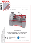
8YflkPfliE\n(*o+'>\Xi?\X[CXk_\
Your new E:AB8AJ® 13 x 40 Gear Head Lathe has been specially designed to provide many years of
trouble-free service. Close attention to detail, ruggedly built parts and a rigid quality control program
assure safe and reliable operation.
The Model M1098 Gear Head Lathe has precision-ground induction-hardened ways, removable gap with
40" between centers, an oil-bath headstock, threading gearbox, and apron. The 2 HP, 220V, 3-phase
motor drives the spindle at eight speeds. The four-way turret style tool post assures rigid tool holding
and accurate positioning. The Model M1098 includes a coolant pump, steady and follow rests, three and
four-jaw chucks, a 10" faceplate, and an MT#3 tailstock taper. The lathe is made of cast iron throughout
and has flame-hardened headstock gears.
Woodstock International, Inc. is committed to customer satisfaction in providing this manual. It is our
intent to make sure all the information necessary for safety, ease of assembly, practical use and durability of this product be included.
-3-
@EKIF;L:K@FE
D('0/(*o+'>\Xi?\X[CXk_\
@EKIF;L:K@FE
D('0/(*o+'>\Xi?\X[CXk_\
Jg\Z`]`ZXk`fej
Spindle Motor .............................2 HP, 6.5 A, 1.5 KW, 220V, Three-Phase, 1725 RPM
Overall Length .................................................................................... 78"
Overall Depth .................................................................................. 29.5"
Footprint ................................................................................70.5" x 15.5"
Height ............................................................................................52.5"
Bed Width......................................................................................... 7.3"
Swing Over Bed ................................................................................... 13"
Swing Over Gap .................................................................................18.3"
Swing Over Saddle ............................................................................... 7.8"
Distance Between Centers ......................................................................40"
Height of Center Line ........................................................................... 6.5"
Compound Slide Travel..........................................................................3.2"
Cross Slide Travel ................................................................................ 6.3"
Tailstock Barrel Travel ..........................................................................3.9"
Leadscrew Diameter......................................................................... 22 mm
Feed Rod ...................................................................................... 19 mm
Cutting Tool Maximum Size .......................................................... 16 X 16 mm
Camlock System ................................................................................. D1-4
Spindle Bore ...................................................................................... 1.5"
Spindle Taper ................................................................................... MT#5
Tailstock Diameter ........................................................................... 32 mm
Tailstock Taper ................................................................................. MT#3
Spindle Speeds ........................................................................ 70-2000 RPM
Feed Rate Range .................................................................. 0.14-0.376 mm/r
Thread Range (Inch) .................................................................... 2.25–40 TPI
Thread Range (Metric) ................................................................... 0.4-7 mm
Bed Ways.....................................................................1660 x 186 x 308 mm
Longitudal Feed ..................................................................0.052-1.392 mm/r
Cross Feed ....................................................................... 0.014-0.376 mm/r
Approximate Shipping Weight ............................................................ 1433 lbs.
Approximate Net Weight.................................................................. 1279 lbs.
-4-
@EKIF;L:K@FE
D('0/(*o+'>\Xi?\X[CXk_\
:fekifcjXe[=\Xkli\j
D
A
B
C
F
H
E
I
J
L
K
M
N
O
P
G
AM
Q
R
AF
AK
S
AH
T
U
AO
AO
W
V
Z
AN
AG
AJ
AI
AD
AE
AC
AB
AA
X
Y
The Model M1098 lathe.
8%
9%
:%
;%
<%
=%
>%
?%
@%
A%
B%
C%
D%
E%
F%
G.
H%
I%
J%
K%
Headstock
Spindle Speed Levers
Spindle
Chuck and Chuck Guard
Four-Way Tool Post
Work Light
Compound Rest and Handwheel
Steady Rest
Cross Slide and Handwheel
Coolant Hose
Dead Center and Quill
Follow Rest
Quill Lock
Tailstock Lock
Splash Guard
Tailstock Handwheel
Tailstock
Bed Ways
Bed
Lead Screw
L% Feed Rod
M% Rack
N% Thread Dial
O% Apron Oil Level Sight Glass
P% Spindle Rotation ON/OFF
Q% Half-Nut Lever
88% Power Feed Lever
89% Carriage Apron
8:% Longitudinal Feed Handwheel
8;% Headstock Oil Level Sight Glass
8<% Foot Brake
8=% Coolant Pump ON/OFF
8>% Thread Selection Dials
8?% Jog Button
8@% Emergency Stop
8A% Oil Level Sight Glass
8B% Power Lamp
8D% Lead Screw/Feed Rod Direction Lever
8E% Gap
8F% Lathe lifting location (4 locations)
-5-
D('0/(*o+'>\Xi?\X[CXk_\
J8=<KP
J8=<KP
I<8;D8EL8C9<=FI<FG<I8K@E>D8:?@E<%
=8@CLI<KF=FCCFN@EJKIL:K@FEJ9<CFNN@CC
I<JLCK@EG<IJFE8C@EALIP%
Indicates an imminently hazardous situation which, if not avoided, WILL
result in death or serious injury.
Indicates a potentially hazardous situation which, if not avoided, COULD
result in death or serious injury.
Indicates a potentially hazardous situation which, if not avoided, MAY
result in minor or moderate injury.
EFK@:<
This symbol is used to alert the user to useful information about proper
operation of the equipment, and/or a situation that may cause damage
to the machinery.
JkXe[Xi[JX]\kp@ejkilZk`fej
(% K_fifl^_cpi\X[k_\@ejkilZk`feDXelXcY\]fi\fg\iXk`e^pflidXZ_`e\%Learn the applications,
limitations and potential hazards of this machine. Keep the manual in a safe and convenient place
for future reference.
)% B\\gnfibXi\XZc\XeXe[n\ccc`^_k\[%Clutter and inadequate lighting invite potential hazards.
*% >ifle[Xcckffcj%If a machine is equipped with a three-prong plug, it must be plugged into a threehole grounded electrical receptacle or grounded extension cord. If using an adapter to aid in accommodating a two-hole receptacle, ground using a screw to a known ground.
+% N\Xi\p\gifk\Zk`feXkXcck`d\j%Use safety glasses with side shields or safety goggles that meet
the appropriate standards of the American National Standards Institute (ANSI).
,% 8mf`[[Xe^\iflj\em`ifed\ekj%Do not operate this machine in wet or open flame environments.
Airborne dust particles could cause an explosion and severe fire hazard.
-% <ejli\Xcc^lXi[jXi\j\Zli\cp`egcXZ\and in working condition.
.% DXb\jli\jn`kZ_`j`ek_\F==gfj`k`febefore connecting power to machine.
/% B\\gnfibXi\XZc\Xe#free of clutter, grease, etc.
0% B\\gZ_`c[i\eXe[m`j`kfijXnXp%Visitors must be kept at a safe distance while operating unit.
('% :_`c[giff]pflinfibj_fgwith padlocks, master switches or by removing starter keys.
((% JkfgXe[[`jZfee\Zkk_\dXZ_`e\n_\eZc\Xe`e^#X[aljk`e^fij\im`Z`e^%
-6-
D('0/(*o+'>\Xi?\X[CXk_\
()% ;f efk ]fiZ\ kffc% The machine will do a safer and better job at the rate for which it was
designed.
(*% Lj\Zfii\Zkkffc%Do not force machine or attachment to do a job for which it was not designed.
(,% I\dfm\Z_lZbb\pj#iX^j#Xe[kffcj%Before turning the machine on, make it a habit to check that
all chuck keys and wrenches have been removed.
(-%8mf`[lj`e^Xe\ok\ej`feZfi[%But if you must use one, examine the extension cord to ensure it is
in good condition. Immediately replace a damaged extension cord. Always use an extension cord that
uses a ground pin and connected ground wire. Use an extension cord that meets the amp rating on
the motor nameplate. If the motor is dual voltage, be sure to use the amp rating for the voltage you
will be using. If you use an extension cord with an undersized gauge or one that is too long, excessive
heat will be generated within the circuit, increasing the chance of a fire or damage to the circuit.
(.% B\\ggifg\i]ffk`e^Xe[YXcXeZ\ at all times.
(/% CfZbk_\dfY`c\YXj\]ifddfm`e^Y\]fi\]\\[`e^k_\nfibg`\Z\`ekfk_\dXZ_`e\.
(0% ;f efk c\Xm\ dXZ_`e\ leXkk\e[\[% Wait until it comes to a complete stop before leaving the
area.
)'% G\i]fiddXZ_`e\dX`ek\eXeZ\Xe[ZXi\%Follow lubrication and accessory attachment instructions
in the manual.
)(% B\\gdXZ_`e\XnXp]ifdfg\e]cXd\%Operating machines near pilot lights or open flames creates
a high risk if dust is dispersed in the area. Dust particles and an ignition source may cause an explosion. Do not operate the machine in high-risk areas, including but not limited to, those mentioned
above.
))% @]XkXepk`d\pflXi\\og\i`\eZ`e^ difficulties performing the intended operation, stop using the
machine! Then contact our technical support or ask a qualified expert how the operation should be
performed.
)*% 9\XnXi\k_XkZ\ikX`edXk\i`XcjdXpZXlj\XeXcc\i^`Zi\XZk`fe`eg\fgc\Xe[Xe`dXcj, especially
when exposed to fine dust. Make sure you know what type of material dust you will be exposed to
and the possibility of an allergic reaction.
)+%?XY`kjÇ^ff[Xe[YX[ÇXi\_Xi[kfYi\Xb%Develop good habits in your shop and safety will become
second-nature to you.
-7-
J8=<KP
(+%N\Xigifg\iXggXi\c%Do not wear loose clothing, neck ties, gloves, jewelry, and secure long hair
away from moving parts.
D('0/(*o+'>\Xi?\X[CXk_\
J8=<KP
8[[`k`feXcJX]\kp@ejkilZk`fej
]fi>\Xi?\X[CXk_\j
I<8;Xe[le[\ijkXe[k_`j
\ek`i\ `ejkilZk`fe dXelXc
Y\]fi\lj`e^k_`jdXZ_`e\%
J\i`flj g\ijfeXc `ealip
dXp fZZli `] jX]\kp Xe[
fg\iXk`feXc`e]fidXk`fe`j
efk le[\ijkff[ Xe[ ]fc$
cfn\[% ;F EFK i`jb pfli
jX]\kpYpefki\X[`e^
LJ<k_`jXe[fk_\idXZ_`e\ipn`k_ZXlk`fe
Xe[ i\jg\Zk% 8cnXpj Zfej`[\i jX]\kp ]`ijk#
Xj `k Xggc`\j kf pfli `e[`m`[lXc nfib`e^
Zfe[`k`fej%Efc`jkf]jX]\kp^l`[\c`e\jZXe
Y\ Zfdgc\k\Ç\m\ip j_fg \em`ifed\ek `j
[`]]\i\ek%=X`cli\kf]fccfn^l`[\c`e\jZflc[
i\jlck `e j\i`flj g\ijfeXc `ealip# [XdX^\
kf\hl`gd\ekfigffinfibi\jlckj%
(% I\X[Xe[le[\ijkXe[k_`jdXelXcY\]fi\fg\iXk`e^k_`jdXZ_`e\%
)% ;fefkZc\XiZ_`gjYp_Xe[% Use a brush, and never clear chips while the lathe is turning.
*% 8cnXpjj\c\Zkk_\i`^_kZlkk\i]fik_\afY, Xe[dXb\jli\Zlkk\ijXi\j_Xig% The right tool
decreases strain on the lathe components and provides a better finish.
+% 8cnXpji\dfm\Z_lZbb\p% Never walk away from the lathe with the key in the chuck.
,% DXb\jli\nfibg`\Z\`jgifg\icp_\c[`eZ_lZbY\]fi\jkXik`e^cXk_\% A workpiece thrown from
the chuck will severely injure you or a bystander.
-% KliecXk_\F==Y\]fi\Z_Xe^`e^jg\\[j% The lathe must be turned F== and the spindle brought
to a complete stop before changing gears.
.% >\kXjj`jkXeZ\n_\e`ejkXcc`e^cXi^\Z_lZbj% Large lathe chucks are very heavy and awkward to
hold, so protect your hands and the precision ground ways. Always use a chuck cradle or piece of
plywood over the ways of the lathe.
/% Jlggfik`e^cfe^nfibg`\Z\jif a workpiece extends out of the end of the headstock for a turning
operation, make sure it is supported as not to wobble violently when the lathe is turned on.
0% DXb\jli\nfibg`\Z\_XjX[\hlXk\Zc\XiXeZ\Y\]fi\jkXik`e^dXZ_`e\%Check tool and tool post
clearance, chuck clearance, and saddle clearance before starting the lathe.
('%8cnXpjlj\k_\Xggifgi`Xk\]\\[Xe[jg\\[iXk\j%
((%E\m\iXkk\dgkkfjcfnfijkfgk_\cXk_\Z_lZbYplj`e^pfli_Xe[%
()%DX`ekX`e`e^XjX]\nfibgcXZ\% Never leave lathe unattended while it is running.
(*%8mf`[`e^Xj\m\i\\ekXe^c\d\ek`ealip% Long hair, ponytails, loose clothing and sleeves is an
entanglement hazard. Make sure they are all tied out of the way and do not dangle.
(+. Gi\m\ek`e^cXk_\ZiXj_\j% Release any automatic feeds after completing a job.
-8-
D('0/(*o+'>\Xi?\X[CXk_\
8mf`[`e^Gfk\ek`Xc@eali`\j
J8=<KP
=`^li\(%Always protect the bed ways, and
unplug the lathe when retooling the lathe.
=`^li\*% Always wear face and eye protection
when using lathes.
=`^li\)%Never walk away from the lathe leaving the chuck key inserted in the chuck.
=`^li\+% Never use hands to stop or slow the
chuck when shutting down the lathe.
=`^li\,%Never wear loose clothing or gloves
when working with the lathe.
-9-
D('0/(*o+'>\Xi?\X[CXk_\
))'M*$g_Xj\Fg\iXk`fe
<C<:KI@:8C
The E:AB8AJ Model M1098 power supply requirement
is 220 volt, three-phase. If you do not have three-phase
power available, you will have to install a phase converter.
We recommend that you hard-wire this lathe to a dedicated circuit with a verified ground, using the circuit breaker
size given below. Never replace a circuit breaker with one
of higher amperage without consulting a qualified electrician to ensure compliance with wiring codes. @]pflXi\
lejli\XYflkk_\n`i`e^Zf[\j`epfliXi\XfipflgcXe
kf Zfee\Zk pfli dXZ_`e\ kf X j_Xi\[ Z`iZl`k# pfl dXp
Zi\Xk\ X ]`i\ _XqXi[ÇZfejlck X hlXc`]`\[ \c\Zki`Z`Xe kf
i\[lZ\k_`ji`jb%
If you must use a plug and receptacle, you will need a
NEMA-style 15-15 plug and receptacle (j\\=`^li\-).
;FEFKXkk\dgkkfnfibfepflij_fg
\c\Zki`ZXc jpjk\d `] pfl Xi\ lejli\
XYflk \c\Zki`ZXc Zf[\j Xe[ n`i`e^
J\\bXjj`jkXeZ\]ifdXhlXc`]`\[\c\Z$
ki`Z`Xe%@^efi`e^k_`jnXie`e^ZXeZXlj\
\c\ZkifZlk`fe
:8LK@FE1 Using a circuit breaker rated higher than
10 amps will increase the risk of fire!
<ok\ej`fe:fi[j
DO NOT use an extension cord for 220V/440V high
amperage industrial shop machines. You must follow all
local electrical codes when connecting this machine to a
power source.
OFF
>ifle[`e^
This machine must be grounded! If you have any
questions about correct electrical installation, contact
a qualified electrician for assistance to make sure all
connections are safe and adhere to your local electrical
codes.
KLIEF==Xe[CF:Bpfli
dXjk\igfn\ijn`kZ_jf
ef gfn\i `j XmX`cXYc\
kf k_\ cXk_\ Y\]fi\
Zfee\Zk`e^ \c\Zki`ZXc
n`i\j @] pfl `^efi\
k_`j nXie`e^ j\i`flj
\c\Zki`ZXc j_fZb dXp
fZZli# ZXlj`e^ `ealip fi
[\Xk_
G
G
Z
Z
X
X
W
W
15-15P
15-15R
=`^li\-% Typical 220V 3-phase 15 Amp
4-prong plug and receptacle.
-10-
D('0/(*o+'>\Xi?\X[CXk_\
J<KLG
LegXZb`e^
The E:AB8AJ Model M1098 has been carefully packaged for safe transporting. If you notice the machine has
been damaged, please contact your authorized E:AB
8AJ dealer immediately.
@k\djE\\[\[]fiJ\kLg
The following items are needed, but not included, to
setup your machine:
Fork Lift or 1.5-Ton Hoist
1.5 Ton lifting straps and hooks
Precision Level
Safety Glasses (for each person)
Solvent for cleaning
Shop Rags for cleaning
Floor Anchors
J<KLG
•
•
•
•
•
•
•
I<8;Xe[le[\ijkXe[k_`j\ek`i\`ejkilZ$
k`fe dXelXc Y\]fi\ lj`e^ k_`j dXZ_`e\%
J\i`flj g\ijfeXc `ealip dXp fZZli `]
jX]\kpXe[fg\iXk`feXc`e]fidXk`fe`jefk
le[\ijkff[ Xe[ ]fccfn\[% ;F EFK i`jb
pflijX]\kpYpefki\X[`e^
K_\Df[\cD('0/n\`^_jXggifo`dXk\$
cp ()/' cYj% J\i`flj g\ijfeXc `ealip
dXp fZZli `] jX]\ dfm`e^ d\k_f[j Xi\
efk ]fccfn\[% Pfl n`cc e\\[ gfn\i
c`]k`e^ \hl`gd\ek Xe[ Xjj`jkXeZ\ kf
i\dfm\ k_`j dXZ_`e\ ]ifd k_\ ZiXk\%
Fk_\in`j\#j\i`fljg\ijfeXc`ealipdXp
fZZli%
JL==F:8K@FE
?8Q8I;
@dd\[`Xk\cp [`jZXi[
Xcc gcXjk`Z YX^j Xe[
gXZb`e^ dXk\i`Xcj kf
\c`d`eXk\ Z_fb`e^&jl]$
]fZXk`fe _XqXi[j ]fi
Z_`c[i\eXe[Xe`dXcj%
-11-
D('0/(*o+'>\Xi?\X[CXk_\
@em\ekfip
The following is a description of the main components
shipped with the E:AB8AJ® Model M1098. Lay the
components out to inventory them.
B
D
C
DX`e:fek\ekj=`^li\. HKP
8% Model M1098 Gear Head Lathe ..........................1
9% Steady Rest .................................................1
:% Follow Rest .................................................1
;% Three-Jaw Chuck ..........................................1
A
J<KLG
8ZZ\jjfipDflek`e^j=`^li\/
<% 10" Faceplate...............................................1
I% 8" Four-Jaw Universal Chuck ............................1
>% Four-Jaw Chuck Key.......................................1
?% Hardware Bag
• Camlock Studs ...........................................3
• Camlock Stud Fasteners ................................3
=`^li\.% Main contents.
Kffc9fo:fek\ek=`^li\0
@% Tool Box .....................................................1
A% Oil Gun ......................................................1
B% Open End Wrenches 10/12, 14/17, 17/19 .........1 EA
C% Slotted Screwdriver .......................................1
D% Phillips Head Screwdriver ................................1
E% Three-Jaw Chuck Jaws ...................................3
F% Hex Wrenches 3, 4, 5, 6, 8, 10MM ..................1 EA
G% MT#3 Dead Centers........................................2
H% MT#5-#3 Morse Taper Sleeve .............................1
I% Center Sleeve MT#5 to MT#3 ............................1
J% Three-Jaw Chuck Key .....................................1
K% Tool Post Wrench ..........................................1
L% Change Gear 40T) ........................................1
F
E
H
G
=`^li\/% Accessories.
If any parts appear to be missing, examine the packaging carefully to be sure those parts are not among the
packing materials. If any parts are missing, find the
part number in the back of this manual and contact
Woodstock International, Inc. at (360) 734-3482 or at
[email protected]
I
J
U
Q
K
P
L
R
EFK@:<
O
S
T
M
N
N_\efi[\i`e^i\gcXZ\d\ekgXikj#i\]\ikfk_\gXikj
c`jkXe[[`X^iXd`ek_\YXZbf]k_\dXelXc%
=`^li\0% Tool box contents.
-12-
D('0/(*o+'>\Xi?\X[CXk_\
:c\Xe`e^DXZ_`e\
The ways and other unpainted parts of your Gear Head
Lathe are coated with a waxy grease that protects them
from corrosion during shipment. Clean this grease off
with a solvent cleaner or citrus-based degreaser. DO NOT
use chlorine-based solvents such as brake parts cleaner
or acetone—if you happen to splash some onto a painted
surface, you will ruin the finish.
*-NXcc:c\XiXeZ\
,(%,
(,%,
DXZ_`e\GcXZ\d\ek
=cffiCfX[1 Your Gear Head Lathe represents a
large load (1279 Lbs.) distributed in a 70 1/2" x 15 1/2"
footprint. We recommend placing this machine on
concrete floors only.
Nfib`e^:c\XiXeZ\j1 Consider existing and
anticipated needs, size of material to be processed
through the machine, and space for auxiliary stands,
work tables or other machinery when establishing a
location for your gear head lathe (see =`^li\(').
C`^_k`e^1 Lighting should be bright enough to
eliminate shadow and prevent eye strain.
<c\Zki`ZXc1Electrical circuits must be dedicated or
large enough to handle amperage requirements.
Outlets must be located near each machine, so
power or extension cords are clear of high-traffic
areas. Follow local electrical codes for proper
installation of new lighting, outlets, or circuits.
-13-
.'%,
(+)%,
=`^li\('% Minimum wall clearances.
D8B< pfli j_fg ÈZ_`c[ jX]\%É <ejli\
k_Xk pfli nfibgcXZ\ `j `eXZZ\jj`Yc\ kf
pfle^jk\ij Yp Zcfj`e^ Xe[ cfZb`e^ Xcc
\ekiXeZ\j n_\e pfl Xi\ XnXp% E<M<I
Xccfn lekiX`e\[ m`j`kfij `e pfli j_fg
n_\e Xjj\dYc`e^# X[aljk`e^ fi fg\iXk$
`e^\hl`gd\ek%
J<KLG
8CN8PJ nfib `e n\cc$m\ek`cXk\[
Xi\Xj ]Xi ]ifd gfjj`Yc\ `^e`k`fe
jfliZ\j n_\e lj`e^ jfcm\ekj kf
Zc\Xe dXZ_`e\ip% DXep jfcm\ekj
Xi\ kfo`Z n_\e `e_Xc\[ fi
`e^\jk\[%Lj\ZXi\n_\e[`jgfj`e^
f] nXjk\ iX^j Xe[ kfn\cj kf Y\
jli\k_\p;FEFKZi\Xk\]`i\fi
\em`ifed\ekXc_XqXi[j%
E<M<I lj\ ]cXddXYc\j jlZ_ Xj ^Xj fi
fk_\ig\kifc\ld$YXj\[jfcm\ekjkfZc\Xe
pflidXZ_`e\%K_\j\gif[lZkj_Xm\cfn
]cXj_ gf`ekj Xe[ gi\j\ek k_\ i`jb f]
\ogcfj`feXe[j\m\i\g\ijfeXc`ealip
D('0/(*o+'>\Xi?\X[CXk_\
Dflek`e^CXk_\feJ_fg
=cffi
Although not required, we recommend that you mount
your new machine to the floor. Because this is an
optional step and floor materials may vary, floor mounting hardware is not included. Generally, you can either
bolt your machine to the floor or mount it on machine
mounts. Both options are described below. Whichever
option you choose, it will be necessary to use a precision
level to level your machine.
J<KLG
9fck`e^kf:feZi\k\=cffij
Lag shield anchors with lag bolts (=`^li\(() and anchor
studs (=`^li\()) are two popular methods for anchoring
an object to a concrete floor. We suggest you research
the many options and methods for mounting your
machine and choose the best that fits your specific application.
=`^li\((% Typical lag shield anchor and
lag bolt.
EFK@:<
8eZ_fijkl[jXi\jkife^\iXe[dfi\g\idXe\ekXck\i$
eXk`m\jkfcX^j_`\c[XeZ_fij2_fn\m\i#k_\pn`ccjk`Zb
flkf]k_\]cffi#n_`Z_dXpZXlj\Xki`gg`e^_XqXi[`]
pfl[\Z`[\kfdfm\pflidXZ_`e\XkXcXk\igf`ek%
Lj`e^DXZ_`e\Dflekj
Using machine mounts, shown in =`^li\(*, gives the
advantage of fast leveling and vibration reduction. The
large size of the foot pads distributes the weight of the
machine to reduce strain on the floor.
=`^li\()% Typical anchor stud.
=`^li\(*% Machine mount example.
-14-
D('0/(*o+'>\Xi?\X[CXk_\
?Xe[n_\\c?Xe[c\j
KfXkkXZ_k_\_Xe[c\j#[fk_\j\jk\gj1
Cross feed
Handwheel
Using the screwdriver, attach the handles (=`^li\(+) to
the threaded hole in the handwheels.
Longitudinal
Handwheel
K\jkIle
The purpose of the test run is to make sure the lathe
operates correctly before proceeding with additional
set up. Check to make sure that the auto feed is not
engaged, the chuck is secure in the spindle, and there
are no loose parts around the spindle. Set the lathe to
the slowest RPM before the test run.
=`^li\(+% Longitudinal and cross feed
handle locations.
KfY\^`ek_\k\jkilegifZ\[li\#[fk_\j\jk\gj1
(%
Make sure there are no obstructions around or
underneath the spindle.
*%
Set the lathe to (0'IGD. Refer to GX^\** to
adjust RPM.
+%
Put on safety glasses, and make sure any bystanders
are wearing safety glasses and are out of the way.
,%
Plug the lathe in, or move the power supply lever at
the power supply panel to FE. The power lamp on
the lathe will then illuminate.
• If it does not illuminate, disconnect power to the
machine, and inside of the main electrical box,
move the circuit breaker to the FE position.
-%
Move the Jg`e[c\IfkXk`feFE&F== lever so the
chuck turns. The lathe should run smoothly, with
little or no vibration or rubbing noises.
• If you hear squealing or grinding noises,turn
the machine F== immediately and unplug the
machine. Correct any problem before further
operation.
• If the the problem is not readily apparent, refer
to KiflYc\j_ffk`e^ on GX^\+/.
.%
Turn the lathe F== and complete the Jg`e[c\
9i\Xb$@e on GX^\*+ before using the lathe.
-15-
J<KLG
)% Make sure the lathe is lubricated and all gear box
oil levels are full. Refer toClYi`ZXk`fe on GX^\*0.
D('0/(*o+'>\Xi?\X[CXk_\
FG<I8K@FEJ
>\e\iXc
EFK@:<
Complete the Jg`e[c\9i\Xb$@e procedure on GX^\*+
before using this lathe for any cutting or threading
operations.Fk_\in`j\^\XiYfo[XdX^\n`ccfZZli%
The Model M1098 will perform many types of operations
that are beyond the scope of this manual. Many of these
operations can be dangerous or deadly if performed incorrectly.
FG<I8K@FEJ
The instructions in this section are written with the understanding that the operator has the necessary knowledge
and skills to operate this machine. @] Xk Xep k`d\ pfl
Xi\\og\i`\eZ`e^[`]]`Zlck`\jg\i]fid`e^Xepfg\iXk`fe#
jkfglj`e^k_\dXZ_`e\
8cnXpjn\XijX]\kp^cXjj\jn_\efg\i$
Xk`e^k_\>\Xi?\X[CXk_\%=X`cli\kf
ZfdgcpdXpi\jlck`ej\i`fljg\ijfeXc
`ealipi\hl`i`e^Xe\p\gXkZ_%
If you are an inexperienced operator, we strongly recommend that you read books, trade articles, or seek training
from an experienced lathe operator before performing
any unfamiliar operations. 8Yfm\Xcc#pflijX]\kpj_flc[
Zfd\]`ijk
Klie`e^FeGfn\i
See =`^li\(,, once plugged in, there is power to the
lathe at all times unless it is unplugged or the main
power panel lever is moved to the F== position. When
illuminated, the power light on the lathe indicates that
the power is being supplied to the lathe. If you press the
emergency stop button, the power light will go out and
cut power to potential machine operations only. Twisting
the EMERGENCY STOP button and letting it pop out will
restore power to machine operations. To completely, cut
all power to the lathe, it must be unplugged, or the main
shop power supply lever must be moved and locked in
the F== position.
;FEFK`em\jk`^Xk\gifYc\djfiX[aljk
k_\ >\Xi ?\X[ CXk_\ n_`c\ `k `j ile$
e`e^%NX`klek`ck_\dXZ_`e\`jklie\[
f]]#legcl^^\[Xe[Xccnfib`e^gXikj
_Xm\Zfd\kfXZfdgc\k\jkfgY\]fi\
gifZ\\[`e^
Power Light
Emergency Stop
Efk\1 K_\Jg`e[c\IfkXk`feFE&F==C\m\ifek_\Xgife
jkXikjk_\jg`e[c\dfkfi`eXgXik`ZlcXi[`i\Zk`fe%
=`^li\(,% Power light and emergency
stop locations.
-16-
D('0/(*o+'>\Xi?\X[CXk_\
K_i\\$AXn;`i\ZkDflek
JZifcc:_lZb
Three-jaw scroll chucks feature hardened steel jaws that
self-center the workpiece within 0.002"-0.003". An extra
set of jaws is included for machining larger workpieces.
The three-jaw direct mount scroll chuck featured in these
instructions has three cam-lock studs that mount directly
to the chuck and hold the chuck tight to the spindle
nose.
Kfi\dfm\fidflekpflik_i\\$aXn[`i\ZkdflekjZifcc
Z_lZbpfln`cce\\[k_\]fccfn`e^kffcj1
•
•
•
•
Chuck Key
Dead Blow Hammer
A Chuck Cradle or a piece of plywood large enough
to span the bedways and support the weight of the
chuck
Breaker Bar (optional)
G@E:? ?8Q8I; Gifk\Zk pfli _Xe[j
Xe[ gi\Z`j`fe ^ifle[ Y\[nXpj
n`k_ gcpnff[ n_\e i\dfm`e^ cXk_\
Z_lZb K_\ _\Xmp n\`^_k f] X ]Xcc$
`e^ Z_lZb ZXe ZXlj\ j\i`flj `ealip%
Kfi\dfm\k_\\o`jk`e^Z_lZb#[fk_\j\jk\gj1
(% DISCONNECT POWER TO THE LATHE!
*.
Loosen the 3 cam-locks by turning the chuck key
counterclockwise until the mark on the cam-lock
aligns with the single mark on the spindle nose in
=`^li\(.% This will be approximately one-third of a
turn. If you look carefully, you will see the cam-lock
rise up out of the spindle nose. If the cam-lock stud
does not freely release from the cam-lock, wiggle
the cam-lock until the cam-lock stud releases.
FG<I8K@FEJ
)% Lay a chuck cradle or protective layer of plywood
over the bedways to protect the precision ground
surfaces from damage and to prevent fingers from
being pinched (see =`^li\(-).
=`^li\(-%Simple chuck cradle made of
scrap lumber.
Efk\1 K_\j\ZXd$cfZbjdXpY\m\ipk`^_k%8Yi\Xb\i
YXidXpY\lj\[kfX[[c\m\iX^\%
=`^li\(.%Loosening the cam-locks.
-17-
D('0/(*o+'>\Xi?\X[CXk_\
+%
Using a dead blow hammer or other soft mallet,
lightly tap around the outer circumference of the
chuck body to break the chuck free from the camlocks and from the spindle nose taper.
CXi^\ Z_lZbj Xi\ m\ip _\Xmp% 8cnXpj ^\k Xjj`jkXeZ\
n_\e i\dfm`e^ fi `ejkXcc`e^ cXi^\ Z_lZbj kf gi\m\ek
g\ijfeXc `ealip fi [XdX^\ kf k_\ Z_lZb fi cXk_\%
,%
With a rocking motion, carefully remove the chuck
from the spindle nose (see =`^li\(/).
Kf`ejkXcck_\k_i\\$aXnjZifccZ_lZb#[fk_\j\jk\gj1
Spindle Nose Taper
=`^li\(/%Installing and removing a small
chuck.
(% DISCONNECT POWER TO THE LATHE!
FG<I8K@FEJ
)% Lay a chuck cradle or protective layer of plywood
over the bedways to protect the precision ground
surfaces from damage and to prevent fingers from
being pinched.
*%
If the three-jaw scroll chuck does not have the camlock studs assembled, screw the cam-lock studs into
the chuck body.
+%
Measure the height of the cam-lock studs from the
previously installed chuck (see =`^li\(0).
,%
Adjust the cam-lock studs in the three-jaw chuck to
match the measurement from the previous chuck.
=`^li\(0% Measuring height of cam-lock
studs.
Efk\1 Ki`Xc$Xe[$\iifiX[aljkd\ekn`ccY\e\\[\[`]
pfl[fefk_Xm\Xgi\m`fljZXd$cfZbjkl[kfi\]\i$
\eZ\%
-%
Once the proper length is obtained, thread the cap
screws to lock the cam-lock studs into position.
.%
Lift the chuck, and insert the studs onto the spindle
nose.
/%
Tighten each cam-lock clockwise until you feel the
cam-lock engage the cam-lock stud. Continue to
turn until you can't turn any further. You will see
the chuck body draw-up to the spindle nose. Ideally
the cam-lock mark will fall between the two pointed
arrows on the spindle nose (see =`^li\)').
-18-
=`^li\)'%Tightening the cam-locks.
D('0/(*o+'>\Xi?\X[CXk_\
KfcfX[Xnfibg`\Z\#[fk_\j\jk\gj1
(%
With the chuck key, open the jaws so the workpiece
lays flat against the chuck face and jaw step, or
fits in the through hole. For jaw and work holding
options, see=`^li\)(.
)%
Turn each jaw until it makes contact with the
workpiece.
:cXdg`e^feXeFlkj`[\;`Xd\k\i
*% Turn the chuck by hand to make sure you have even
contact with all three jaws and the workpiece is not
off center.
• If the workpiece is off center, loosen the jaws and
adjust the workpiece.
:cXdg`e^`eXe@ej`[\;`Xd\k\i
=`^li\)(% Loading a workpiece.
• If the workpiece is seated correctly, tighten the
jaws.
I\gcXZ`e^AXnj
=`^li\))% Jaw number identification.
Three-jaw scroll chucks come with two sets of hardened steel jaws. The outside jaws are used to hold the
workpiece from the outer diameter. The inside jaws are
for holding larger work usually from the inside diameter.
The inside jaws can hold a workpiece from the outside
when held in the central position (see =`^li\)().
The jaws are numbered 1–3 and must be installed in this
sequence (see =`^li\))).
-19-
FG<I8K@FEJ
J\Zli\cp ZcXdg pfli nfibg`\Z\ Xe[
i\dfm\ k_\ Z_lZb b\p K_ifne fYa\Zkj
]ifdXcXk_\ZXeZXlj\j\i`flj`ealipfi
[\Xk_kfk_\fg\iXkfiXe[kfYpjkXe[\ij
dXep]\\kXnXp%
D('0/(*o+'>\Xi?\X[CXk_\
Kfi\dfm\Xj\kf]aXnj#[fk_\j\jk\gj1
(% DISCONNECT POWER TO THE LATHE!
)% Identify the jaw position by the number usually
stamped on the side of the jaw groove (see =`^li\
)*).
Jaw Number
Efk\1K_\Z_lZb_XjXeldY\i`ek_\aXn^l`[\k_Xk
Zfii\jgfe[jkfk_\aXneldY\ij\\=`^li\)* %@]
`k[f\jefk#cfZXk\k_\aXneldY\ifek_\aXnXe[
dXibk_\Z_lZbkf`[\ek`]pk_Xkgfj`k`fe%
*.
+.
Turning the chuck key counterclockwise, back the
jaws out of the chuck body. They will be released
from the scroll thread in a reverse sequence.
=`^li\)*%Typical jaw number location.
Jaw Guide Number
Set the jaws aside in a safe place.
Kf`ejkXccXj\kf]aXnj#[fk_\j\jk\gj1
(% DISCONNECT POWER TO THE LATHE!
FG<I8K@FEJ
)% Identify the jaw by the number stamped on the side.
*%
Locate the corresponding jaw guide on the chuck
body (see =`^li\)+).
+.
Insert the chuck key into the chuck.
,.
Look into the jaw guide and you will see the scroll
rotating as you turn the chuck key. When the leading thread of the scroll comes into view at the top
of the #1 jaw guide, stop turning the chuck key (see
=`^li\),).
-.
Slide jaw #1 into the jaw guide until it stops.
..
Turn the chuck key so the leading thread of the scroll
picks up the first thread on the jaw. When the lead
thread engages, you will see the jaw being drawn to
the center of the chuck (see =`^li\),).
=`^li\)+% This chuck has jaw references
on the inside of the jaw guide. (Chuck
removed from spindle for clarity).
Lead Thread
=`^li\),% Lead thread on scroll.
-20-
D('0/(*o+'>\Xi?\X[CXk_\
/%
Continue to turn the chuck key until the leading
thread of the scroll comes to the second jaw guide
(see =`^li\)-).
0%
Repeat Jk\gj,Æ. with jaw #2.
Lead Thread
('% Continue to turn the chuck key until the leading
thread of the scroll comes to the third jaw guide.
((% Repeat Jk\gj,Æ. with jaw #3.
=`^li\)-%Lead thread coming in to view
for jaw #2.
Lead Thread
-21-
FG<I8K@FEJ
=`^li\).%Lead thread coming in to view
for jaw #3.
D('0/(*o+'>\Xi?\X[CXk_\
=fli$AXn;`i\ZkDflek
@e[\g\e[\ek:_lZb
Four-jaw chucks feature hardened steel jaws that are
adjusted independently. Each jaw can be removed from
the chuck body and reversed. Independent jaw adjustment and reversal allows for a wide range of work holding versatility.
The four-jaw direct mount independent chuck featured in
these instructions mounts the same way as the three-jaw
chuck. Refer to the three-jaw chuck instructions beginning on GX^\(.%
FG<I8K@FEJ
CXi^\Z_lZbjXi\m\ip_\Xmp%8cnXpj_Xm\Xjj`jkXeZ\
n_\e i\dfm`e^ fi `ejkXcc`e^ cXi^\ Z_lZbj kf gi\m\ek
g\ijfeXc `ealip fi [XdX^\ kf k_\ Z_lZb fi cXk_\%
G@E:? ?8Q8I; Gifk\Zk pfli _Xe[j
Xe[ gi\Z`j`fe ^ifle[ Y\[nXpj
n`k_ gcpnff[ n_\e i\dfm`e^ cXk_\
Z_lZb K_\ _\Xmp n\`^_k f] X ]Xcc$
`e^ Z_lZb ZXe ZXlj\ j\i`flj `ealip%
=`^li\(%Simple chuck cradle made of
scrap lumber.
-22-
D('0/(*o+'>\Xi?\X[CXk_\
KfcfX[Xnfibg`\Z\`ek_\]fli$aXnZ_lZb#[fk_\j\
jk\gj1
(%
Using the chuck key, open each jaw so the
workpiece will lay flat against the chuck face.
)%
Support the workpiece.
*%
Lock the tailstock and then turn the tailstock quill
so the dead center makes contact or is close to the
center point of your workpiece (see=`^li\)/).
+%
Turn each jaw until it just makes contact with the
workpiece.
=`^li\)/% Clamping workpiece.
,% In an opposing pattern, tighten each jaw in small
increments. After you have adjusted the first jaw,
continue tightening the opposing jaw. Check the
dead center alignment frequently to make sure
you have not wandered off your index point due to
applying too much pressure to a single jaw.
After the workpiece is held in place, back the
tailstock away and rotate the chuck by hand. The
center point will move if the workpiece is out of
center.
.%
Make fine adjustments by slightly loosening one jaw
and tightening the opposing jaw until the workpiece
is precisely aligned. Use a dial indicator for fine tuning adjustments in alignment (see=`^li\)0).
/%
Use a lower RPM when machining heavy eccentric
workpieces.
-23-
=`^li\)0% Centering workpiece.
FG<I8K@FEJ
-%
D('0/(*o+'>\Xi?\X[CXk_\
=XZ\gcXk\
The faceplate can be used to turn non-cylindrical parts or
for off-center turning by clamping the workpiece to the
faceplate.
Kf`ejkXcck_\]XZ\gcXk\#[fk_\j\jk\gj1
Installing the faceplate follows the same steps as any of
the lathe chucks. Install according to the instructions for
three-jaw chucks found on GX^\(..
FG<I8K@FEJ
KfcfX[Xnfibg`\Z\#[fk_\j\jk\gj1
(.
Support the workpiece.
)%
Slide the tailstock to the workpiece.
*%
Lock the tailstock and then turn the tailstock quill so
the dead center makes contact with the center point
of your workpiece. For more information refer to
:\ek\ij in this section on GX^\)0%
+%
Lock the tailstock quill when sufficient pressure is
applied to hold the workpiece in place. Depending
on the workpiece, some additional support may be
needed.
,%
Secure the workpiece with a minimum of three independent clamping devices (see =`^li\*'). Failure
to follow this step may lead to deadly injury to yourself or bystanders. Take into account rotation and
the cutting forces applied to the workpiece when
clamping to the faceplate. DXb\jli\pfliZcXdg`e^
Xggc`ZXk`fen`ccefk]X`c
-%
Use a lower RPM when machining heavy eccentric
workpieces.
=`^li\*'% Typical faceplate with properly
clamped workpiece in four locations.
Lj\ X d`e`dld f] k_i\\ `e[\g\e[\ek
ZcXdg`e^[\m`Z\jn_\eklie`e^\ZZ\eki`Z
nfibg`\Z\j% =X`cli\ kf gifm`[\ X[\hlXk\
ZcXdg`e^ n`cc ZXlj\ nfibg`\Z\ kf \a\Zk%
J\Zli\cp ZcXdg pfli nfibg`\Z\ Xe[
i\dfm\k_\Z_lZbb\pK_ifnefYa\Zkj
]ifdXcXk_\ZXeZXlj\j\i`flj`ealipfi
[\Xk_kfk_\fg\iXkfiXe[kfYpjkXe[\ij
dXep]\\kXnXp%
-24-
D('0/(*o+'>\Xi?\X[CXk_\
>XgG`\Z\I\dfmXc
The Model M1098 comes equipped with a gap piece below
the spindle that can be removed for turning large diameter parts or when using a large diameter faceplate.
The gap piece is installed, then ground at the factory
during lathe assembly for precise fit and alignment.
Factors during the remaining assembly apply additional
forces to the gap; therefore, replacing the gap to the
original position will be very difficult. @]pflZ_ffj\kf
i\dfm\k_\^Xgg`\Z\#n\[feki\Zfdd\e[Xkk\dgk$
`e^kfi\gcXZ\`k%
Taper Pins
Kfi\dfm\k_\^Xgg`\Z\#[fk_\j\jk\gj1
Find the two taper pin nuts located on the bed of
the gap piece (see =`^li\ *().
)%
Using an open-ended wrench, tighten the nut. This
will cause the taper pin to release. Remove the
taper pin and repeat for the second nut.
*%
Remove the four socket head cap screws.
+%
Tap the outside of the gap piece with a dead blow
hammer to loosen, and remove the gap piece.
-25-
=`^li\*(% Lathe gap piece.
FG<I8K@FEJ
(%
D('0/(*o+'>\Xi?\X[CXk_\
KX`cjkfZb
The tailstock (=`^li\*)) of the Model M1098 lathe can
be used to support workpieces with the use of a live or
dead center. It can drill or bore holes in the center of a
part, using a drill chuck fitted with a #3 taper and a drill
bit, or bypass the drill chuck and use a #3 tapered shank
drill bit. Tthe tailstock can also be used for cutting shallow tapers by using the offset adjustment.
Kffg\iXk\k_\kX`cjkfZb#[fk_\j\jk\gj1
Tailstock Lock
(%
Slide the tailstock to the desired position.
)%
Pull up on the tailstock lock handle to lock the
tailstock in place.
Quill Lock
Lever
Stop
Posts
=`^li\ *)% Tailstock and quill lock handles
in locked position.
Kffg\iXk\k_\kX`cjkfZbhl`cc#[fk_\j\jk\gj1
FG<I8K@FEJ
Quill Feed
(%
With the tailstock locked, push down the quill lock
handle to unlock.
)%
Turn the quill feed handle clockwise to feed/move
the quill towards the spindle, or counterclockwise to
move away from the spindle.
*%
Pull up on the quill lock handle to lock the quill in
place.
;i`cc`e^n`k_k_\KX`cjkfZb
Kf`ejkXcck_\kXg\i\[[i`ccZ_lZb#[fk_\j\jk\gj1
(%
With the tailstock locked, push down to unlock the
quill lock handle.
)%
Turn the quill feed handle clockwise to extend the
quill about one inch.
*%
Insert a tapered drill arbor (=`^li\**), or the
tapered drill shank (=`^li\*+), into the quill until
the taper is firmly seated. The matching tapers hold
the arbor.
+%
Turn the quill feed handle clockwise to feed the drill
bit into the rotating workpiece.
,%
To remove the chuck taper, turn the quill feed handle counterclockwise until the chuck is pushed out
from the tailstock taper.
-26-
=`^li\**% Setting up tailstock for drilling.
=`^li\*+% Tapered shank drill fitting into
quill taper.
D('0/(*o+'>\Xi?\X[CXk_\
:lkk`e^J_XccfnKXg\ij
n`k_k_\KX`cjkfZb
The tailstock can be offset to cut a shallow taper on a
part.
Lock
Screw
Right Jack Screw
Kfj\klgk_\kX`cjkfZbkfZlkkXg\ij#[fk_\j\jk\gj1
(%
Lock the tailstock in position.
)%
Loosen the lock screw (see =`^li\*,).
*%
Alternately loosen and tighten the left and right
jack screws until the desired offset is indicated on
the scale (see =`^li\*-).
+%
Retighten the lock screw.
Efk\1 Kfi\kliek_\kX`cjkfZbYXZbkfk_\fi`^`eXc
gfj`k`fe#i\g\Xkk_\gifZ\jjlek`ck_\Z\ek\i\[gfj`$
k`fe`j`e[`ZXk\[fek_\jZXc\%
=`^li\ *,% Tailstock off-set adjustments.
KX`cjkfZb8c`^ed\ek
Left Jack
Screw
Scale
KfXc`^ek_\kX`cjkfZb#[fk_\j\jk\gj1
(%
Using a precision level on the bedways, make sure
the lathe is level side-to-side and front-to-back. If
the lathe is not level, correct this condition before
proceeding.
)%
Get two pieces of steel round stock, 2.00" in diameter x 6.00" long.
*%
Center drill both ends of one piece of the round
stock. Set it aside for use in Jk\g-%
+%
Using the other piece of stock, make a dead center
by turning a shoulder to make a shank. Flip the piece
over in the chuck and turn a 60º point (see =`^li\
*.)%
Continued on next page
-27-
=`^li\*-% Off-set scale.
=`^li\*.% Tailstock centering dead
center.
FG<I8K@FEJ
The tailstock on the Model M1098 is aligned at the factory
with the headstock. We recommend that you take the
time to ensure that the tailstock is aligned to your own
desired tolerances.
D('0/(*o+'>\Xi?\X[CXk_\
Efk\1 8jcfe^Xjk_\[\X[Z\ek\ii\dX`ej`ek_\
Z_lZb#k_\gf`ekf]pfliZ\ek\in`cci\dX`ekil\kf
k_\jg`e[c\Xo`j%B\\g`ed`e[k_Xkk_\gf`ekn`cc
_Xm\kfY\i\]`e`j_\[n_\e\m\i`k`ji\dfm\[Xe[
i\klie\[kfk_\Z_lZb%=fidfi\`e]fidXk`fei\]\i
kf:\ek\ijfeGX^\)0`ek_`jj\Zk`fe%
,%
Place the live center in the tailstock.
-%
Attach a lathe dog to the bar stock and mount it
between centers (see =`^li\*/)%
.%
Turn approximately 0.010" off the diameter.
/%
Measure the stock with a micrometer.
=`^li\*/% Checking tailstock alignment.
• If the stock is fat at the tailstock end, the
tailstock needs to be moved toward the operator
half the distance of the amount of the taper (see
=`^li\*0).
FG<I8K@FEJ
• If the stock is thinner at the tailstock end, the
tailstock needs to be moved away from the operator half the distance of the amount of the taper
(see =`^li\+').
0%
Mount a dial indicator so the dial plunger is on the
tailstock barrel before making adjustments to the
tailstock.
('% Refer to :lkk`e^J_XccfnKXg\ijN`k_K_\KX`cjkfZb
on GX^\).for making adjustments to the tailstock
center. Turn another 0.010" off of the diameter and
check for a taper. Repeat this process as necessary
until the desired amount of accuracy is achieved.
=`^li\*0% Tailstock adjustment option
#1.
=`^li\+'% Tailstock adjustment option
#2.
-28-
D('0/(*o+'>\Xi?\X[CXk_\
:\ek\ij
The dead center is used in the tailstock to support
workpieces. When used in the tailstock, make sure to
keep the dead center tip and workpiece lubricated.
The Model M1098 lathe is supplied with two MT#3 dead
centers, one is HSS and one is carbide tipped. The supplied MT#5-#3 sleeve fits into the spindle taper to hold
the MT#3 center.
Kf`ejkXccX[\X[fic`m\Z\ek\i#[fk_\j\jk\gj1
Feed the quill out about 1" so that the dead center
can be inserted.
)%
Insert the dead center into the quill opening.
Matching tapers provide the locking action (see
=`^li\+().
*%
Move the tailstock into position and lock in place.
+%
Feed the quill into the workpiece.
Efk\1DXb\jli\k_\i\`jXZ\ek\i[i`cc\[_fc\`e
k_\\e[f]k_\nfibg`\Z\]fik_\[\X[Z\ek\i%
,%
Lock the quill into place once the live center and
the part rotate together. The quill may need to be
adjusted during operation.
-%
To remove the dead center, retract the quill until
the dead center pops free.
The dead center can also be used in the spindle. The
most common application is when using the faceplate (see
=`^li\ +)).
Kf `ejkXcc k_\ [\X[ Z\ek\i `e k_\ jg`e[c\# [f k_\j\
jk\gj1
(%
Remove the chuck from the spindle.
)%
Install the dead center in the spindle sleeve.
*%
Install the sleeve and center into the spindle opening.
+%
Attach the faceplate to the spindle.
Efk\1 N_\elj`e^k_\[\X[Z\ek\i`ek_\jg`e[c\#
lj\XcXk_\[f^jfk_XkpfligXikn`ccifkXk\n`k_
k_\jg`e[c\Xe[efkjg`efek_\[\X[Z\ek\ik`g%
-29-
=`^li\+(% Inserting dead center.
=`^li\+)% Faceplate and dead center
setup.
EFK@:<
=X`cli\kfb\\g[\X[Z\ek\igf`ekn\cc
clYi`ZXk\[n`cc[XdX^\[\X[Z\ek\iXe[
nfibg`\Z\%
FG<I8K@FEJ
(%
D('0/(*o+'>\Xi?\X[CXk_\
Jk\X[pI\jk
The steady rest serves as a support for long shafts (l/d ratio
of 3:1 or greater). The steady rest can be placed anywhere
along the length of the part.
Kf`ejkXcc&lj\k_\jk\X[pi\jk#[fk_\j\jk\gj1
Knurled
Knob
(% Place the steady rest on the lathe bedways so the
triangular notch fits over the angled portion of the
rear bedway.
)%
FG<I8K@FEJ
*%
Loosen the three set screws so the finger position can
be adjusted (see =`^li\ +*).
Loosen the knurled knob (see =`^li\+*) and open the
steady rest so a workpiece can fit inside of the fingers
(see =`^li\ ++).
+%
Position the steady rest where desired. Tighten the
bolt at the base of the steady rest to secure in place.
,%
Close the steady rest so that the workpiece is inside
the fingers and tighten the knob.
-%
Set the fingers snug to the workpiece and secure by
tightening the three set screws. Fingers should be
snug and allow rotational movement of the workpiece.
Lubricate the finger tips with an anti-seize grease during operation.
.%
After prolonged use, the fingers will show wear. Either
mill or file the tips for a new contact surface.
Knob
Set Screws
=`^li\+*% Steady rest adjustments.
Finger Adjustment Knobs
=`^li\++% Positioning workpiece in steady
rest.
=fccfnI\jk
The follow rest in =`^li\+, is mounted on the saddle and follows the movement of the tool. It can be
attached/removed by two socket head cap screws located
at the base of the follow rest. The follow rest requires
only two fingers, as the cutting tool acts as the third.
The follow rest is used on long, slender parts to prevent
flexing of the workpiece from the pressure of the cutting
tool.
The sliding fingers are set similar to those of the steady
rest—free of play but not binding. Always lubricate during
operation. Remove the follow rest from the saddle when
not in use. After prolonged use, the fingers will need to be
milled or filed to cleanup the contact surface.
-30-
=`^li\+,% Follow rest attachment.
D('0/(*o+'>\Xi?\X[CXk_\
J\kk`e^:fdgfle[Jc`[\
The compound slide is used to cut tapers on parts or to
set the proper infeed angle when threading. It may also
be used to cut specific lengths longitudinally, when set
parallel to the spindle axis.
Cap
Screws
Compound Slide
The compound slide handwheel has a graduated dial for
precise inch feed increments. The base of the compound
slide has a graduated scale for angular setup.
Kfj\kk_\Xe^lcXigfj`k`fe#[fk_\j\jk\gj1
(%
Loosen the two cap screws, one on each side of the
compound slide (see =`^li\+-).
)%
Rotate the compound slide to the desired angular
position. Use the scale at the base of the slide and
the indicator marks on the carriage to set the position.
*%
=`^li\+-% Compound slide set at an
angle.
Tool Post Bolts
Tighten the two cap screws. Be sure to not overtighten, as you may strip threads.
=fli$NXpKffcGfjk
FG<I8K@FEJ
The four-way tool post is mounted on top of the compound slide, and allows a maximum of four tools to be
loaded simultaneously.
The four-way tool post allows for quick indexing to new
tools. This is accomplished by rotating the top handle
counterclockwise and then rotating the tool post to the
desired position. Rotate the top handle clockwise to lock
the tool into position.
=`^li\+.% Tool holder and tool post.
EFK@:<
KfcfX[k_\kffcgfjk#[fk_\j\jk\gj1
@dd\[`Xk\cp i\dfm\ kffc gfjk ni\eZ_
X]k\i lj\% Kffc gfjk ni\eZ_ Zflc[ Y\
g`Zb\[lgYpZ_`gXe[k_ifne%
(%
Choose the desired cutting tool.
)%
Loosen the tool post bolts so that the cutting tool
can fit underneath.
*%
Use a minimum of two tool post bolts to hold down
the cutting tool and tighten firmly (see =`^li\+.).
+%
Repeat Jk\gj($* for the three remaining openings,
as needed.
-31-
D('0/(*o+'>\Xi?\X[CXk_\
=ffk9iXb\
The Model M1098 lathe comes equipped with a foot brake
(see =`^li\+/ % The foot brake is intended to be used
primarily as a time saving tool. The best method for using
the foot break is turn the spindle F== and then apply
pressure to the foot brake with your foot, slowing the
spindle to a stop.
Stepping on the foot brake while the spindle is FEwill
kill the power to the spindle control lever and will bring
the spindle to a stop. Stopping the spindle in this manner is harder on the machine and should be reserved for
emergency situations. Once stopped, the control lever
will then need to be returned to the neutral position. The
power light will show the power is still FE. Only the circuit to the Spindle Rotation ON/OFF Lever will be interrupted.
Efk\1 ;fefkZfe]lj\k_`j]\Xkli\n`k_k_\\d\i^\eZp
jkfgYlkkfe%K_\\d\i^\eZpjkfgYlkkfeZlkjgfn\ikf
k_\dXZ_`e\Xe[dljkY\i\j\kkfi\jkfi\gfn\ikfk_\
cXk_\%
Spindle Control Lever
Foot Brake
=`^li\+/% Foot brake and spindle control
lever.
Compound Slide Handwheel
Cross Feed
Handwheel
FG<I8K@FEJ
DXelXc=\\[
You can manually move the cutting tool around the lathe
with three methods. This section will review the individual controls on the carriage and provide descriptions
of their uses (see =`^li\+0).
Cfe^`kl[`eXc?Xe[n_\\c
Longitudinal Handwheel
The longitudinal handwheel moves the carriage left or
right along the bed. This control is helpful when setting
up the machine for turning or when manual movement is
desired during turning operations.
:ifjj=\\[?Xe[n_\\c
The cross slide handwheel moves the top slide toward
and away from the work. Turning the dial clockwise
moves the slide toward the workpiece. The graduated
dial can be adjusted by holding the handwheel with one
hand and turning the dial with the other.
:fdgfle[Jc`[\?Xe[n_\\c
The compound slide handwheel controls the position of
the cutting tool relative to the workpiece. The compound
slide is adjustable for any angle within its range. The
graduated dial is adjustable using the same method as
the dial on the cross slide. Angle adjustment is controlled
by cap screws on the base of the compound slide.
-32-
=`^li\+0% Carriage controls.
D('0/(*o+'>\Xi?\X[CXk_\
J\kk`e^IGD
Kf[\k\id`e\Xe[j\kk_\e\\[\[Zlkk`e^IGD1
(%
:lkk`e^Jg\\[j]fi?`^_Jg\\[Jk\\c
?JJ :lkk`e^Kffcj
Use the table in =`^li\,' to determine the cutting
speed required for the material of your workpiece.
=X`cli\ kf ]fccfn IGD Xe[ ]\\[ iXk\ ^l`[\c`e\j dXp
k_i\Xk\efg\iXkfijX]\kp]ifd\a\Zk\[gXikjfiYif$
b\ekffcj%
)%
Determine the final diameter, in inches, for the cut
you are about to take.
Efk\1 =fik_`jjk\gpfln`cce\\[kfXm\iX^\flkk_\
[`Xd\k\ijfinfibn`k_k_\]`e`j_[`Xd\k\i]fipfli
ZXcZlcXk`fej%
*%
:lkk`e^Jg\\[o+ 4IGD
;`Xd\k\if]:lk
+%
With the calculated RPM, decide on the closest cutting RPM to what you need.
,%
Make sure the spindle is completely stopped before
proceeding.
-%
Move the levers to the RPM that is closest to your
calculated RPM. The long lever (Range Lever) selects
High or Low range, and the shorter lever (RPM Lever)
selects the RPM in that range (=`^li\,().
Efk\1 PfldXpe\\[kfifkXk\k_\jg`e[c\Yp_Xe[
kf^\kk_\c\m\ijkfgifg\icp\e^X^\%
Cutting Speed
(sfm)
Aluminum & alloys
300
Brass & Bronze
150
Copper
100
Cast Iron, soft
80
Cast Iron, hard
50
Mild Steel
90
Cast Steel
80
Alloy Steel, hard
40
Tool Steel
50
Stainless Steel
60
Titanium
50
Plastics
300-800
Wood
300-500
Efk\1 =fiZXiY`[\Zlkk`e^kffcj#[flYc\
k_\Zlkk`e^jg\\[%K_\j\mXcl\jXi\X
^l`[\c`e\fecp%
Refer to the D8:?@E<IPJ?8E;9FFB for
more detailed information.
=`^li\,'% Cutting speed table for HSS
cutting tools.
Range
Lever
RPM
Lever
=`^li\ ,(% Spindle speed selector levers.
-33-
FG<I8K@FEJ
Use the following formula to determine the needed
RPM for your operation:
Workpiece Material
D('0/(*o+'>\Xi?\X[CXk_\
Jg`e[c\9i\Xb$@e
It is essential to closely follow the proper break-in procedure to ensure correct bearing and gear tooth seating and
mating. Complete this process once you have familiarized
yourself with all instructions in this manual.
KfY\^`ek_\Yi\Xb$`egifZ\[li\#[fk_\j\jk\gj1
EFK@:<
=X`cli\ kf ]fccfn jkXik lg Xe[ jg`e[c\
Yi\Xb$`e gifZ\[li\j n`cc ZXlj\ iXg`[
[\k\i`fiXk`fef]jg`e[c\[i`m\jpjk\d%
FG<I8K@FEJ
(% Check oil levels in headstock and apron. Correct
oil levels if required. Refer to ClYi`ZXk`fein the
D8@EK<E8E:<section on GX^\*0of this manual.
)%
Make sure there are no obstructions around or underneath the spindle.
+%
Set the spindle speed to 190 RPM, refer to section
J\kk`e^IGD on GX^\**%
,%
Turn the lathe power FE#andmove the Jg`e[c\
IfkXk`feFE&F==C\m\i(=`^li\,)) to either the
FORWARD or REVERSE position, and verify that the
spindle rotates in the proper direction.
-%
Let the lathe run for a minimum of 10 minutes.
.%
Turn the lathe F==, change gears to the next highest
RPM and repeat this step for each RPM setting in Low
and High Range.
/%
Change the headstock lubricant, refer to GX^\*0.
=`^li\,)% Spindle Rotation ON/OFF
Lever.
Cross slide feed rate will be 0.438" travel
per revolution of the chuck, and the longitudal feed rate will be 0.127" travel per
revolution of the chuck.
J\kk`e^Gfn\i=\\[IXk\
The carriage has longitudinal and cross slide power feed
capabilities. Efk\1 K_\j\`ejkilZk`fejXi\mXc`[n`k_X
Zflek\iZcfZbn`j\ifkXk`fef]k_\jg`e[c\cffb`e^Xkk_\
Z_lZb%8cc[`i\Zk`feji\m\ij\n_\ejg`e[c\ifkXk`fe`j
i\m\ij\[%
Kfj\kXe[\e^X^\k_\gfn\i]\\[#[fk_\j\jk\gj1
(%
From your cutting and feed rate calculations, select
the feed rate that you need from the chart (see
=`^li\,*).
)%
Install the 40 tooth change gear at location X shown
on the chart.
*%
Turn the feed dials to the setting indicated on the
chart. Efk\1PfldXpe\\[kfifkXk\k_\Z_lZbYp
_Xe[fidfm\k_\cfe^`kl[`eXc_Xe[n_\\ckf^\k
j\c\ZkfijXe[^\Xijkf\e^X^\%
-34-
=`^li\,*% Selecting power feed rate.
D('0/(*o+'>\Xi?\X[CXk_\
+%
Make sure the half nut lever shown in =`^li\,+ is
disengaged.
,%
Use the feed selector lever shown in =`^li\,, to
engage the cross feed or longitudal feed when needed.
-%
Use the Jg`e[c\IfkXk`feFE&F==C\m\i(=`^li\
,,) to start the lathe and the power feed operation
when needed.
Spindle Rotation
ON/OFF Lever
Half Nut Lever
EFK@:<
=\\[iXk\`jYXj\[fejg`e[c\IGD%?`^_]\\[iXk\j
ZfdY`e\[n`k__`^_jg`e[c\jg\\[ji\jlck`eXiXg`[cp
dfm`e^ZXii`X^\fiZifjjjc`[\%GXpZcfj\Xkk\ek`fekf
k_\]\\[iXk\pfl_Xm\Z_fj\eXe[Y\i\X[pkfglj_
k_\]ffkYiXb\%=X`cli\kf]lccple[\ijkXe[k_`jn`cc
ZXlj\k_\ZXii`X^\kfZiXj_`ekfk_\jg`e[c\%
EFK@:<
Up: Cross Feed
Central:
Feeds is
Disengaged
Down: Longitudinal Feed
=`^li\,,% Feed selector lever.
-35-
FG<I8K@FEJ
DXb\ jli\ Xcc gfn\i ]\\[ j\kk`e^j Xi\ [`j\e^X^\[
Y\]fi\ jkXik`e^ k_\ cXk_\ K_fifl^_cp ]Xd`c`Xi`q\
pflij\c] n`k_ Xcc k_\ Zfekifcj Xe[ k_\`i ]leZk`fej
Y\]fi\lj`e^gfn\i]\\[
=`^li\,+% Disengaging half nut lever.
D('0/(*o+'>\Xi?\X[CXk_\
K_i\X[J\kk`e^j
The Model M1098 lathe is capable of cutting inch and
metric threads. Most inch threads can be cut without
changing out gears. Metric threads and a few inch threads
require that you change the gears.
Thread cutting will be three threads per
inch.
Kf[\k\id`e\k_i\X[j\kk`e^j#[fk_\j\jk\gj1
(%
Calculate your required cutting speed, and move the
spindle RPM levers so it will run at the closest RPM.
)%
Determine the threads per inch (TPI) for inch
threads or pitch for metric threads.
*%
Install the +' tooth gear at position X, and the *'
tooth gear at position Y as shown on the chart (see
=`^li\,-).
+%
Turn the feed dials to the setting indicated on the
chart (see =`^li\,-).
FG<I8K@FEJ
Efk\1PfldXpe\\[kfifkXk\k_\Z_lZbYp_Xe[fi
dfm\k_\cfe^`kl[`eXc_Xe[n_\\ckf^\kj\c\Zkfij
Xe[^\Xijkf\e^X^\%
,%
Move the feed selector lever to the central position
shown in =`^li\,. to disengage the cross feed or
longitudal feed.
-%
Use the Jg`e[c\IfkXk`feFE&F==C\m\ito start the
lathe when needed.
.%
Use the half nut lever to engage and disengage the
apron for threading operations.
=`^li\,-% Feed and thread chart in TPI
and metric pitch.
Half Nut Lever
Central Position: Feed is Disengaged
=`^li\ ,.% Apron control levers.
-36-
D('0/(*o+'>\Xi?\X[CXk_\
:_Xe^\>\Xij
The Model M1098 lathe comes with 40, 127, 120, and 30
tooth gears installed. One extra 40 tooth gear is included
so gear ratios can be altered for threading operations.
The charts on the machine indicate which ratios are
applicable for an intended operation.
Thumb
Knob
KfZ_Xe^\k_\^\Xij#[fk_\j\jk\gj1
(%
DISCONNECT POWER TO THE LATHE!
)%
Remove two thumb knobs and remove the headstock
gear cover to expose the change gears (=`^li\,/).
Loosen the gear adjuster (=`^li\,0),and let the
gear swing down.
+%
Remove the appropriate change gear according to
your the chart, and install the required gear (see
=`^li\,0).
,%
Mesh the gear teeth, and tighten the gear adjuster
back in place so there is a slight amount of geartooth backlash, approximately from 0.002" to 0.005".
Efk\1J\kk`e^k_\^\Xijkffk`^_kn`ccZXlj\\oZ\j$
j`m\n\XiXe[ef`j\%J\kk`e^k_\^\Xijkffcffj\dXp
ZXlj\jc`ggX^\Xe[gfjj`YcpYi\Xb^\Xik\\k_%
Gear
Adjuster
-% Oil the gears, reinstall the gear cover, and reconnect power to the machine.
>\XiiXk`f`jXj]fccfnj1
+'KÇ5()'K
().KÇ5+'K
=`^li\,0% Change gear locations.
-37-
FG<I8K@FEJ
*%
=`^li\ ,/% Gear cover.
D('0/(*o+'>\Xi?\X[CXk_\
K_i\X[`e^Fg\iXk`fe
FG<I8K@FEJ
(%
Set the compound rest to the appropriate angle
for the given thread you want to cut. For a Unified
National Series thread, this is 29º off of perpendicular to the spindle axis.
)%
Set the tool tip perpendicular to the workpiece and
center it vertically.
*%
Make sure the thread dial is engaged with the lead
screw. If not, use a hex wrench to loosen the screw
and rotate the thread dial until the gear engages
with the lead screw, then tighten the screw to hold
the dial in place.
+%
Select the RPM you want to use. A slower RPM will
give you more time to react especially if threading
over a short distance or threading up to a shoulder.
,%
Set the feed direction lever for either right or lefthanded threads.
-%
With the feed rate selectors to the appropriate settings, turn FE the spindle to verify settings. Check
to see that the lead screw is turning and verify that
the apron moves in the correct direction by engaging the half nut lever shown in =`^li\-'.
.%
Once you are confident the settings are correct, disengage the half nut and turn F== the spindle.
/%
Examine the indicator table on the machine or in
=`^li\-(to determine which numbers (on the
thread dial) will engage the half nut.
Efk\1 K_\i\Xi\XkfkXcf]\`^_kdXibjfek_\
k_i\X[[`Xc#`eZcl[`e^k_\eldY\ij($+%8epdXib
ZXeY\lj\[kfZlk\m\eeldY\i\[k_i\X[j%Lj\k_\
eldY\i\[c`e\j#(#)#*#fi+kfZlkf[[eldY\i\[
k_i\X[j%KfdX`ekX`eXZZliXZpXe[Zfej`jk\eZp#
\e^X^\k_\_Xc]elkfek_\jXd\dXibfe\XZ_gXjj%
=X`cli\kfjkXikfek_\jXd\eldY\i\XZ_k`d\dXp
c\X[kfZlkk`e^f]]k_\k_i\X[dX[\`ek_\gi\m`flj
gXjj%
0%
If cutting metric threads, you will not use the thread
dial. Once the half nut is engaged, you must leave it
engaged until the threads are complete.
-38-
EFK@:<
=X`cli\ kf ]fccfn IGD Xe[ ]\\[ iXk\
^l`[\c`e\j `e k_`j dXelXc n`cc glk
le[l\jkiX`efedfm`e^gXikj#j_fik\e
kffc c`]\# Xe[ Zi\Xk\ gffi nfibg`\Z\
i\jlckj%
Thread Dial
Half Nut Lever
=`^li\-'% Half nut and thread dial
location.
=`^li\-(% Thread dial chart.
D('0/(*o+'>\Xi?\X[CXk_\
D8@EK<E8E:<
>\e\iXc
Regular periodic maintenance on your E:AB8AJ®
Model M1098 will ensure its optimum performance. Make
a habit of inspecting your machine each time you use it.
:_\Zb]fik_\]fccfn`e^Zfe[`k`fejXe[i\gX`ifi
i\gcXZ\n_\ee\Z\jjXip1
Loose mounting bolts.
Worn switch or safety features.
Worn or damaged cords and plugs.
Damaged V-belt.
Any other condition that could hamper the safe
operation of this machine.
:c\Xe`e^
Make sure to unplug the lathe before cleaning it. Clean
your machine every day or more often as needed.
Remove chips as they accumulate. Chips left on the
machine soaked with water based coolant will eventually
invite oxidation and gummy residue to build up around
moving parts. Cleaning will help keep your lathe running
smoothly. Always be safe and responsible with the use
and disposal of cleaning products.
D8B< JLI< k_Xk pfli dXZ_`e\ `j
legcl^^\[ [li`e^ Xcc dX`ek\eXeZ\ gif$
Z\[li\j@]k_`jnXie`e^`j`^efi\[#j\i`$
fljg\ijfeXc`ealipdXpfZZli%
Headstock Oil Sight Glass
Gear Box
Oil Sight
Glass
ClYi`ZXk`fe
=`^li\-)% Oil sights and filler locations.
Headstock Oil Drain Behind Gear
Gear Box Oil Drain
=`^li\-*% Headstock and gear box drain
locations.
-39-
D8@EK<E8E:<
The headstock, gear box and apron can use any quality ISO 32 hydraulic oil. Keep the oil levels at 3/4-full as
seen in the sight glasses (see =`^li\j-), -*#and-+).
After break-in, change the oil in the headstock after three
months. After that change the all oils at the same time
on an annual basis or more frequently if extreme machine
use requires it.
D('0/(*o+'>\Xi?\X[CXk_\
For daily lubrication, use the manual oil gun with the same
gear box lubricant to lubricate all oil fittings. To control
surface rust on machined surfaces, wipe the unprotected
metal as required with this same oil.
Apron Oil Fill
KfclYi`ZXk\k_\cXk_\#[fk_\j\jk\gj1
(% Wipe off the oil port before and after oiling to keep
out contaminants.
Apron Oil Sight Glass
)% Oil all ball fittings daily with one to two shots of oil.
See =`^li\-,for some typical locations.
These areas include:
• Cross Slide, Compound Rest, and Carriage
• Tailstock, Lead Screw, and Feed Rod
• Handwheels, Ways, Change Gear Teeth, and Axles
Apron Oil Drain
=`^li\-+% Apron lubrication references.
:ffcXekJpjk\d
KfdX`ekX`ek_\ZffcXekjpjk\d#[fk_\j\jk\gj1
(% Remove the four screws and pump access cover, and
slide out the pump and reservoir (see =`^li\--).
)%
Empty the old coolant and remove large chips from
1st and 2nd stage separators.
*% Fill the reservoir with approximately three gallons of
coolant solution.
D8@EK<E8E:<
+%
=`^li\-,%Typical ball fitting locations.
Open the valve on the coolant nozzle.
,% Turn the coolant pump FEto prime the coolant system and to see if the coolant is cycling properly.
-% Reinstall the pump access cover.
9@FCF>@:8CXe[GF@JFE
?8Q8I;
The reservoir on this machine is designed to store coolant. During storage some fluids grow dangerous microbes, or collect toxic heavy metals in the fluid making
it a biological and poison hazard.
• To prevent infections and poisoning, use the correct
personal protection equipment when handling
coolant.
• To properly dispose of toxic coolant, follow federal,
state, and fluid manufacturer procedures.
-40-
=`^li\--%Coolant pump and reservoir.
EFK@:<
=X`cli\kf]fccfnclYi`ZXk`fe^l`[\c`e\j
n`cc c\X[ kf iXg`[ [\k\i`fiXk`fe f]
cXk_\Zfdgfe\ekj%
D('0/(*o+'>\Xi?\X[CXk_\
J<IM@:<
>\e\iXc
This section covers the most common service adjustments
or procedures that may need to be made during the life
of your machine.
:ifjj=\\[9XZbcXj_
Backlash is the amount of play found in a lead screw.
It can be found by turning the cross slide handwheel in
one direction, and then turning the handwheel the other
direction. When the cross slide begins to move, the backlash has been taken up.
Kfi\dfm\\oZ\jj`m\YXZbcXj_#[fk_\j\jk\gj1
(%
Tighten the socket head cap screw in small increments (see =`^li\-.).
)% Test after each adjustment until the backlash meets
the needs of the operator and operation.
D8B< JLI< k_Xk pfli dXZ_`e\ `j
legcl^^\[ [li`e^ Xcc j\im`Z\ gifZ\$
[li\j @] k_`j nXie`e^ `j `^efi\[# j\i`$
fljg\ijfeXc`ealipdXpfZZli%
Cross Feed Backlash
Adjustment Cap Screw
Efk\18mf`[k_\k\dgkXk`fekffm\ik`^_k\ek_\jfZb$
\k_\X[ZXgjZi\n%Fm\ik`^_k\e`e^n`ccZXlj\\oZ\j$
j`m\n\Xikfk_\jc`[`e^YcfZbXe[c\X[jZi\n%
>`Yj
The saddle, cross feed, compound rest, and tailstock gibs
can all be adjusted on the Model M1098 lathe.
Efk\1 N_\eX[aljk`e^^`Yj#b\\g`ed`e[k_Xkk_\^fXcf]
^`YX[aljkd\ek`jkfi\dfm\jcfgg`e\jjn`k_flkZXlj`e^
k_\jc`[\jkfY`e[%Cffj\^`YjdXpZXlj\gffi]`e`j_\jfe
k_\nfibg`\Z\Xe[dXpZXlj\le[l\n\Xifek_\jc`[\%
Fm\i$k`^_k\e`e^dXpZXlj\gi\dXkli\n\Xifek_\jc`[\#
c\X[jZi\n#Xe[elk%
=`^li\-.%Cross feed backlash
adjustment socket head cap screw.
KfX[aljkk_\jX[[c\^`Y#[fk_\j\jk\gj1
J<IM@:<
(%
Loosen four hex nuts found at the bottom rear of
the cross slide and back off one full turn each (see
=`^li\-/).
=`^li\-/%Saddle gib adjustments.
-41-
D('0/(*o+'>\Xi?\X[CXk_\
)%
Turn the four square head bolts with a hex wrench
until a slight resistance is felt when moving the saddle. DO NOT overtighten.
*%
Move the carriage with the handwheel to feel the
current drag. Adjust the bolts until the desired drag
is achieved.
Efk\1 Fm\ik`^_k\e`e^n`ccZXlj\\oZ\jj`m\gi\dXkli\
n\Xifek_\^`YjfiZiXZbk_\_flj`e^%
+%
Rear Gib
Screw
Tighten the four hex nuts.
KfX[aljkk_\Zifjj]\\[Xe[Zfdgfle[i\jk^`Yj#[f
k_\j\jk\gj1
(%
Loosen the gib locking set screw and the rear gib
screw approximately one turn. (see =`^li\-0).
)%
Tighten the front gib screw a quarter turn (see
=`^li\.').
=`^li\-0% Rear cross feed gib screw.
Gib
Locking
Set Screws
*% Turn the cross feed handwheel to feel the current
drag and adjust the front screw until the desired
drag is achieved.
+% When satisfied with the adjustment, snug the gib
locking set screw.
Front Gib
Screw
,% Repeat Jk\gj($+ on the compound rest.
=`^li\.'% Front cross feed gib screw.
J<IM@:<
KfX[aljkk_\kX`cjkfZbcfZb#[fk_\j\jk\gj1
(%
Move the tailstock lock handle to the unlocked position.
)%
Slide the tailstock to an area that will allow access
to the hex nut under the tailstock block.
*%
Tighten the tailstock hex nut 1/4 turn. Test to see
that sufficient clamping pressure is applied so the
tailstock will not move. Repeat as necessary (see
=`^li\.().
Hex
Nut is
Under
Block
=`^li\.(% Tailstock lock adjustment.
-42-
D('0/(*o+'>\Xi?\X[CXk_\
I\gcXZ`e^M$9\ck
Kfi\gcXZ\k_\M$Y\ckjfek_\cXk_\#[fk_\j\jk\gj1
(%
DISCONNECT POWER TO THE LATHE!
)%
Remove the change gear cover at from the headstock.
*%
Remove the tension off the old V-belts by loosening
the motor mount hex bolts (see=`^li\.)).
+%
Remove the old belts and install the new ones.
Always replace these belts in pairs.
,%
Tighten the motor mount bolts until you achieve 1⁄4"
of belt deflection when lightly pushed with your finger tips.
-%
Close the change gear cover, and reconnect the
lathe to the power source.
Motor
Mounting Bolts
=`^li\.)%V-belt adjustments.
J<IM@:<
-43-
D('0/(*o+'>\Xi?\X[CXk_\
DX`e<c\Zki`ZXc9fo
Transformer
Circuit
Breaker
Circuit
Breaker
Spindle Motor
Contactors
Pump Relay
Change
Gear Cover
Anti-Start
Limit
Switch
Ground Block
J<IM@:<
Terminal Bar
=`^li\.*% M1098 Electrical panel.
-44-
D('0/(*o+'>\Xi?\X[CXk_\
N`i`e^;`X^iXdD('0/))'M*$G_Xj\
WARNING
1&
,
,
2
6
7
5
5
,
7
3
4
6
Disconnect power to
the lathe before performing any electrical
work, service, or
adjustment.
+-
7
5
6
+-
+-
5 6 7
-
3PINDLE
0H
OFF
-
0UMP
0H
0%
2
4
4#
2
6
1&
3"
31
8
4
31
31
+!
31
(,
LEGEND
%,
+
+!
3!
+-
+!
+-
+-
3"
31
+! +-
+-
J<IM@:<
M = Motor
KM = Contactor
KA = Relay
EL = Work Lamp
HL = Indicator Lamp
SB = Button
SA = Button
SQ = Limit Switch
TC = Transformer
QF = Circuit Breaker
FR = Relay
31
31
-45-
D('0/(*o+'>\Xi?\X[CXk_\
Dfkfi:fee\Zk`fejD('0/))'M*$G_Xj\
Chuck Guard Limit Switch Inside.
=`^li\.+% M1098 chuck guard limit
switch.
Brown
Red
Spindle Motor
220V 3-Ph
W2
U2
v2
U1
V1
W1
Ground
Yellow/Green
Blue
=`^li\.-% M1098 spindle motor.
Black
Black
Black
Pump Motor
220V 3-Ph
Black
Blue
Red
Ground
Yellow/Green
Foot
Brake
Limit
Switch
J<IM@:<
Cover Anti-Start Limit Switch.
Spindle Rotation
Limit Switches.
=`^li\..% M1098 coolant pump motor.
=`^li\.,% M1098 limit switches.
-46-
D('0/(*o+'>\Xi?\X[CXk_\
KiflYc\j_ffk`e^
This section covers the most common Gear Head Lathe problems. DO NOT make any adjustments until
the Gear Head Lathe is unplugged and moving parts have come to a complete stop.
JPDGKFD
Motor will not start.
GFJJ@9C<:8LJ<
:FII<:K@M<8:K@FE
1. Limit switch is triggered.
2. Emergency switch is pushed in.
3. No voltage or open connection.
4. Faulty start capacitor.
Fuses or circuit breakers
trip open.
1. Short circuit in line cord or plug.
2. Short circuit in motor or loose
connections.
3. Incorrect fuses or circuit breakers
in power supply.
1. Install headstock cover, close chuck guard.
2. Rotate emergency switch so it pops out.
3. Test for voltage, close circuit breakers, replace
fuses, test magnetic switches—replace as required.
4. Replace start capacitor.
1. Inspect cord or plug for damaged insulation and
shorted wires and replace extension cord.
2. Inspect all connections on motor for loose or
shorted terminals or worn insulation.
3. Install correct fuses or circuit breakers.
Motor overheats.
1. Motor overloaded.
2. Air circulation through the motor
restricted.
1. Reduce load on motor.
2. Clean out motor to provide normal air circulation.
Carriage hard to move.
1. Carriage lock is tightened down.
2. Chips have loaded up on bedways.
1. Check to make sure table locks are fully released.
2. Frequently clean away chips that load up during
turning operations.
3. Lubricate bedways and handles.
3. Bedways are dry and in need of
lubrication.
4. Longitudinal stops are interfering.
5. Gibs are too tight.
4. Check to make sure that stops are floating and not
hitting the center stop.
5. Loosen gib screw(s) slightly.
Loud, repetitious noise
coming from machine.
1. Chuck is hitting the carriage or
tool post.
1. Shut lathe F== Hit emergency stop button or step
on foot pedal.
Machine is loud when
cutting. Overheats or bogs
down in the cut.
1. Excessive depth of cut.
2. RPM or Feed Rate wrong for
operation.
3. Dull cutters.
1. Decrease depth of cut.
2. Refer to RPM Feed rate chart for appropriate rates.
Tailstock quill will not
feed out of tailstock.
1. Quill lock is tightened down.
1. Unlock.
Bad surface finish.
1. Wrong RPM or feed rate.
2. Dull tooling or poor tool selection.
3. Too much play in gibs.
1. Adjust for appropriate RPM and feed rate.
2. Sharpen tooling or select a better tool for the
intended operation.
3. Tighten gibs.
Gear change levers will
not shift into position.
1. Gears not aligned in headstock.
1. Rotate spindle by hand until gear falls into place.
Can't remove tapered tool
from quill.
1. Quill had not retracted all the way
back into the tailstock.
2. Debris was not removed from
taper before inserting into quill.
1. Turn the quill handwheel until it forces taper out
of quill.
2. Always make sure that taper surfaces are clean.
J<IM@:<
-47-
3. Sharpen or replace cutters.
D('0/(*o+'>\Xi?\X[CXk_\
9\[#C\X[JZi\n#Xe[=\\[If[;`X^iXd
''''J\i`\jGXikj
+0
.'
,*
+.$(
-0
+
*
(
,+$(
(*
)
((
.(
-(
,)
+-
,(
,
,(
)*
))
(-
,*
,+
(0
.
('
,(
),
,/
)/
-.
,+
,0
).
,*
+'
)-
+*
-($(
,)
+(
-/
*0
0
+)
)+
+,
G8IKJ
++
-48-
D('0/(*o+'>\Xi?\X[CXk_\
9XZbjgcXj_#:_`gKiXp#Xe[JkXe[;`X^iXd
''''J\i`\jGXikj
.,
.)
.*
.-
.0
.+
./
/*
..
/'
/(
/)
0(
/+
0)
/,
0'
/-
/.
G8IKJ
//
/0
-49-
D('0/(*o+'>\Xi?\X[CXk_\
<d\i^\eZp9iXb\;`X^iXd
''''J\i`\jGXikj
0*
0+
0,
('('.
('-
('(
00
0-
0/
(',
(''
0.
('/
('+
('*
(')
('0
200
(((
G8IKJ
(('
-50-
D('0/(*o+'>\Xi?\X[CXk_\
''''J\i`\jGXikjC`jk
REF PART #
DESCRIPTION
REF
PART #
DESCRIPTION
1
XM10980001
MOTOR BASE
71
XPS03M
PHLP HD SCR M6-1 X 8
2
3
XM10980002
XM10980003
PULLEY
BED
72
73
XPS19M
M10980073
PHLP HD SCR M5-.8 X 6
COVER
4
XM10980004
GAP
74
M10980074
ELECTRICAL BOX
5
6
XM10980005
XM10980006
END COVER
L-BRACKET
75
76
M10980075
XPS68M
SPALSH GUARD
PHLP HD SCR M6-1 X 10
7
XM10980007
COLLAR-BRACKET
77
XPS47M
PHLP HD SCR M6-1 X 25
9
10
XM10980009
XM10980010
COLLAR
HANDLE
78
79
XPN01M
M10980079
HEX NUT M6-1
OIL PLATE
11
XM10980011
RACK (LONG)
80
XPS68M
PHLP HD SCR M6-1 X 10
13
16
XM10980013
XM10980016
RACK (SHORT)
LEAD SCREW
81
82
M10980081
M10980082
COVER
LEFT BED STAND
19
XM10980019
FEED ROD
83
M10980083
BED STAND
22
23
XM10980022
XM10980023
SHAFT
COLLAR
84
85
M10980084
XPS68M
COVER
PHLP HD SCR M6-1 X 10
24
25
26
XM10980024
XM10980025
XM10980026
SHAFT
HANDLE
BRAKE RING
86
87
88
XPS68M
M10980087
XPSB73M
PHLP HD SCR M6-1 X 10
COVER
CAP SCREW M12-1.75 X 50
27
28
XM10980027
XM10980028
COLLAR
KEY
89
90
M10980089
XPS68M
LEFT PLATE BRACKET
PHLP HD SCR M6-1 X 10
39
40
41
XM10980039
XM10980040
XM10980041
KNOB M8-1.25
PLUG
PLUG
91
92
93
M10980091
M10980092
M10980093
PLATE
RIGHT PLATE BRACKET
BREAK SHAFT
42
43
44
XM10980042
XM10980043
XM10980044
PLUG
SPECIAL SCREW
COVER
94
95
96
XPRP40M
M10980095
M1098096
ROLL PIN 2.5 X 12
BRAKE PULL ROD
CAP-SHAPE SCREW
45
46
47-1
XM10980045
XPSS05M
XPSS11M
KNOB M8-1.25
SET SCREW M5-.8 X 10
SET SCREW M6-1 X 16
97
98
99
XPN01M
XPRP40M
M10980099
HEX NUT M6-1
ROLL PIN 2.5 X 12
PEDAL ARM
49
51
52
53
54
54-1
58
59
61
61-1
67
68
69
70
XPSB47M
XPSB02M
XPSB60M
XPN03M
XPSS19M
XPSB63M
XPRP16M
XPRP71M
XPRP46M
XPRP34M
M10980067
M1098068
XM10980069
XPB14M
CAP SCREW M10-1.5 X 40
CAP SCREW M6-1 X 20
CAP SCREW M8-1.25 X 55
HEX NUT M8-1.25
SET SCREW M8-1.25 X 30
CAP SCREW M12-1.75 X 60
ROLL PIN 3 X 25
ROLL PIN 6 X 22
ROLL PIN 6 X 28
ROLL PIN 6 X 55
COMPRESSION SPRING 1 X 7.5 X 25
OIL BALL 8MM
SET SCREW M8-1.25 X 60
HEX BOLT M10-1.5 X 35
100
101
102
103
104
105
106
107
108
109
110
111
200
M10980100
M10980101
M10980102
XPS39M
XPRP28M
M10980105
XPRP05M
M10980107
M10980108
XPSB71M
XPN02M
M10980111
M10980200
CONNECTING SHAFT
DRAW SPRING
SWITCH BLOCK
PHLP HD SCR M8-1.25 X 10
ROLL PIN 5 X 40
DRIVING SHAFT (LONG)
ROLL PIN 5 X 30
DRVING SHAFT (SHORT)
PEDAL
CAP SCREW M10-1.5 X 60
HEX NUT M10-1.5
BRAKE ROD SUPPORT
SPINDLE MOTOR
G8IKJ
-51-
D('0/(*o+'>\Xi?\X[CXk_\
?\X[jkfZb:Xj\Xe[J_`]k:fekifcj;`X^iXd
('''J\i`\jGXikj
('/.
(''0 (((-
('((
('./
(',(
((**
('+/
(','
('**
(''.
((+/
((+0
(',.
(('*
('00
('0.
('(*
((,(
('-0
(('*
('0.
('-/
((,'
('('
(((+
('(('-+
((+)
((*+
(',- ((*-
((+.
(',)
((+.
((+)
('0*
((*'
((*0
((*+
('-,
((''
('(,
('-('()
('0,
('(+
G8IKJ
('//
((+.
(()'
(()0
('0*
((+(
((+'
('0-
-52-
('0-
D('0/(*o+'>\Xi?\X[CXk_\
Gi`dXipXe[J\Zfe[Xip;i`m\;`X^iXd
('''J\i`\jGXikj
(').
(()+
('.+
(''+
((*/
(()-
('/+
('+(
('+'
('*0
('*/
('*.
(('/
('),
(')(')/
(()((,+
('.*
(')0
((,*
(((0
((,((,,
('',
((,)
('*)
('/-
((,.
(',0
('/'
((,/
((,0
('*('*,
('*'
(('0
('*+
('**
((((
((',
('*(
('*'
('0*
((*.
(''-
G8IKJ
((),
-53-
D('0/(*o+'>\Xi?\X[CXk_\
Jg`e[c\Xe[=\\[>\Xi;i`m\;`X^iXd
('''J\i`\jGXikj
(''*
(()/
('.,
('')
(')+
('+)
((('
('/0
('+*
(()(
('+.
(')*
(('/
(().
('++
(('(()*
('++
('+-
(''/
('+,
('/.
('..
(()*
(''(
(()*
('-.
('.-
('-.
(())
(('.
(',*
(((*
(())
(',+
(')'
((*,
('/,
(('+
('(0
('))
(((.
('.0
((')
(',,
(')(
(((.
G8IKJ
('(/
-54-
('(.
D('0/(*o+'>\Xi?\X[CXk_\
('''J\i`\jGXikjC`jk
DESCRIPTION
REF PART#
DESCRIPTION
1001 XM10981001
COLLAR
1051 XM10981051
ANCHORPIN
1002 XM10981002
1003 XM10981003
COLLAR
REARCOVER
1052 XM10981052
1053 XM10981053
SHAFT
GEAR30T
1004 XM10981004
REARCOVER
1054 XM10981054
SHAFT
1005 XM10981005
1006 XM10981006
PULLEY
PLUG
1055 XM10981055
1056 XM10981056
SHAFT
THRUSTWASHER
1007 XM10981007
MAINCASTING
1057 XM10981057
GEARSHAFT17T
1008 XM10981008
1009 XM10981009
FRONTCOVER
SHIFTLEVER
1059 XM10981059
1064 XM10981064
SPECIALSHOULDERSCREW
LEVER
1010 XM10981010
SHAFTHOUSING
1065 XM10981065
LEVER
1011 XM10981011
1012 XM10981012
COVER
HANDLEBODY
1066 XM10981066
1067 XM10981067
LEVER
COLLAR
1013 XM10981013
CRANKSHAFT
1068 XM10981068
SHIFTFORK
1014 XM10981014
1015 XM10981015
HANDLEBODY
HANDLEBLOCK
1069 XM10981069
1073 XM10981073
SHIFTFORK
GASKET
1016 XM10981016
1017 XM10981017
1018 XM10981018
HUB
GEAR37T
SPACER
1074 XM10981074
1075 XM10981075
1076 XM10981076
GASKET
GASKET
GASKET
1019 XM10981019
1020 XM10981020
SLOTTEDCOLLAR
THRUSTWASHER
1077 XM10981077
1078 XM10981078
GASKET
GASKET
1021 XM10981021
1022 XPW06M
1023 XM10981023
GEAR40T
FLATWASHERM12-1.75
GEAR37T
1079 XM10981079
1080 XM10981080
1084 XPS02M
OILSEAL
OILSEAL
PHLPHDSCRM4-.7X12
1024 XM10981024
1025 XM10981025
1026 XM10981026
SPANNERNUT
GEAR43T
GEAR51T
1085 XPSB24M
1086 XPSB01M
1087 XPSB14M
CAPSCREWM5-.8X16
CAPSCREWM6-1X16
CAPSCREWM8-1.25X20
1027 XM10981027
1028 XM10981028
1029 XM10981029
SPACER
GEARSHAFT16T
COVER
1088 XPSB02M
1089 XPSB06M
1093 XPSS04M
CAPSCREWM6-1X20
CAPSCREWM6-1X25
SETSCREWM6-1X12
1030
1031
1032
1033
1034
1035
1036
1037
1038
1039
1040
1041
1042
1043
1044
1045
1046
1047
1048
1050
CASTWASHER
SHAFT
SPACER
COLLARW/GEAR21T
GEAR29T
GEAR46T
GEAR38T
COLLAR
GEAR26T
GEAR34T
GEAR53T
PLUG
GEAR74T
GEAR37T
SPINDLE
SPRING
PIN
CAM
SHAFT
GEAR51T
1095
1096
1097
1099
1100
1102
1103
1104
1105
1106
1107
1108
1109
1110
1111
1113
1114
1117
1119
SETSCREWM8-1.25X8
SETSCREWM8-1.25X10
SETSCREWM8-1.25X12
PHLPHDSCRM8-1.25X35
PHLPHDSCRM4-.7X10
HEXNUTM12-1.75
KEY5X5X15
KEY5X5X18
KEY5X5X50
KEY6X6X40
KEY6X6X55
KEY6X6X120
KEY6X6X120
KEY8X8X18
KEY5X5X20
ROLLPIN3X10
ROLLPIN4X18
EXTRETAININGRING20
EXTRETAININGRING35
XM10981030
XM10981031
XM10981032
XM10981033
XM10981034
XM10981035
XM10981036
XM10981037
XM10981038
XM10981039
XM10981040
XM10981041
XM10981042
XM10981043
XM10981044
XM10981045
XM10981046
XM10981047
XM10981048
XM10981050
-55-
XPSS20M
XPSS16M
XPSS14M
XPS42M
XPS38M
XPN09M
XPK20M
XPK14M
XPK36M
XPK11M
XPK49M
XPK50M
XPK50M
XPK51M
XPK34M
XPRP44M
XPRP01M
PR09M
PR12M
G8IKJ
REF PART#
D('0/(*o+'>\Xi?\X[CXk_\
('''J\i`\jGXikjC`jk
DESCRIPTION
REF PART#
DESCRIPTION
1120 PR43M
EXTRETAININGRING50MM
1138 XM10981138
O-RING3.1X47
1121 XPR44M
1122 XM1019322
EXTRETAININGRING72
E-CLIP42
1139 XM10981139
1140 XM10981140
COMPRESSIONSPRING1X6X7
COMPRESSIONSPRING1X6X25
1123 XM10981123
BEARING700104E
1141 XM10981141
COMPRESSIONSPRING0.9X4.4X19
1124 XM10981124
1125 XP203
BEARING240E
BEARING203
1126 XM10981126
BEARING204D
1142 XM10981142
1147 XM10981147
1148 XM10981148
SHIFTHUB
LEVERSLEEVE
COVER
1127 XM10981127
1128 XM10981128
BEARING7210E
BEARING7212D
1151 XPSB84M
1152 XM10981152
CAPSCREWM10-1.5X35
CONNECTINGBOARD
1129 XM10981129
STEELBALL5
1153 XPRP49M
ROLLPIN5X25
1130 XM10981130
1133 XM10981133
STEELBALL6
O-RING2.4X14
1154 XM10981154
1155 XM10981155
SHAFT
BREAKSHAFT
1134 XM10981134
O-RING2.4X20
1156 PR03M
EXTRETAININGRING12
1135 XM10981135
1136 XM10981136
O-RING2.4X25
O-RING3.1X30
1157 XM10981157
1158 XM10981158
BREAKSHOE
POSITIONINGAXLE
1137 XM10981137
O-RING3.1X40
1159 PR39M
EXTRETAININGRING8
G8IKJ
REF PART#
-56-
D('0/(*o+'>\Xi?\X[CXk_\
>\XiYfo?flj`e^Xe[J_`]k:fekifcj;`X^iXd
)'''J\i`\jGXikj
)'(/
)'(-
)'(*
)'(+
)'('
)'(.
)'(,
)'(.
)''(
)'')
)'(0
)'(/
)'()
)''*
)'((
)'()'(.
)'))
)'(+ )')*
)''0
)'(0
)'(.
)'(+ )')(
)''+
)')'
)'',
)''-
)'',
)')+
)''-
)''/
)''+
)'),
)''.
)')-
)''.
)').
)')-
)')/
)')0
)').
)'*'
)'*/
)'*'
)'))').
)'*(
)'+(
)'*'
)'*'
)'*)
)'**
)'+'
)'))').
)'*( )'*'
)'*'
)'*'
)'*0
)'*+
)'*,
)'*- )'*.
)'*/
)'*'
G8IKJ
-57-
D('0/(*o+'>\Xi?\X[CXk_\
>\XiYfo;i`m\kiX`e;`X^iXd
)'''J\i`\jGXikj
)'+0
)',)
)',(
)','
)',+
)'-)'-,
)'+/
)'+-
)',*
)',(
)'+.
)'-+
)'),
)'-*
)'+,
)'-)
)',+
)',)',+
)'-( )',)'),
)'.,
)'-'
)'+)
)',0
)'-.
)'.+
)'.) )'.*
)'-/
)',/
)',.
)',+
)'/)'.(
)',)',+
)'.'
)',,
)'/,
)'/+
)'-0
)',+
)',+
)'/*
)'-/
)'0'
)'-.
)'/)
)'/(
)'),
)'/'
)'-( )',)'.0
)'-'
)',0
)'./
)'..
)',/
)',.
)'.)',)',+
)'0.
)'/0 )',)'0)'/)',)',+
)'//
)'), )'0,
)'/.
)'0+
)'),
)'0*
)'++
)'+*
)'-)
)'0)
G8IKJ
)',*
)',+ )'0(
)',,
-58-
)'),
D('0/(*o+'>\Xi?\X[CXk_\
>\XiYfo:_Xe^\>\XiXe[8[aljk\i;`X^iXd
)'''J\i`\jGXikj
)('+
)(',
)('/
)('.
)('-
)(')
)(''
)('*
)'+-
)('(
)'+*
)'+.
)('(
)(')'0/
)(('
)(((
)(()
)'0/
)'00
)('0
)(''
)'0/
G8IKJ
-59-
D('0/(*o+'>\Xi?\X[CXk_\
)'''J\i`\jGXikjC`jk
REF PART#
DESCRIPTION
REF PART#
DESCRIPTION
2001 XM10982001
CASTING
2048 XPK33M
KEY5X5X45
2002 XM10982002
2003 XM10982003
LARGECASTINGCOVER
LARGECASTINGCOVER
2049 XP6203
BEARING6203
2050 XM10982050 BUSHING
2004 XM10982004
DRAINOILFITTING
2051 XM10982051 SPECIALCLIP
2005 XM10982005
2006 XM10982006
"O"-RING17X1.8
SLIDINGBLOCK
2052 XM10982052 GEAR
2053 XM10982053 THRUSTWASHER
2007 XPSB66M
CAPSCREWM8-1.25X65
2054 XP6204
2008 XM10982008
2009 XM10982009
TAPERPIN6X30
EXTENSIONFASTNERM8-1.25
2055 XM10982055 THRUSTWASHER
2056 XPR09M
EXTRETAININGRING20MM
2010 XM10982010
BLOCK
2057 XPR19M
2011 XPRP08M
2012 XM10982012
ROLLPIN6X30
RACK
2058 XM10982058 GEAR
2059 XM10982059 GEAR
2013 XM10982013
BLOCK
2060 XPK38M
2014 XPRP08M
2015 XM10982015
ROLLPIN6X30
RACK
2061 XM10982061 GEAR
2062 XP6204
BEARING6004
2016 XM10982016
2017 XM10982017
2018 XM10982018
SHAFT
RETAININGDOG
"O"-RING8.75X1.8
2063 XM10982063 GASKET
2064 XM10982064 BEARINGCOVER
2065 XM10982065 XIAXLE
2019 XPSS31M
2020 XM10982020
SETSCREWM5-.8X8
BLOCK
2066 XPRP29M
ROLLPIN5X45
2067 XM10982067 BEARINGCOVER
2021 XM10982021
2022 XM10982022
2023 XM10982023
RACK
BLOCK
RACK
2068 XM10982068 GASKET
2069 XM10982069 GEAR
2070 XM10982070 GEAR
2024 XM10982024
2025 XPSB24M
2026 XM10982026
CONTROLRODSUPPORT
CAPSCREWM5-.8X16
GEAR
2071 XM10982071 BUSHING
2072 XM10982072 GEAR
2073 XM10982073 BUSHING
2027 XM10982027
2028 XM10982028
2029 XM10982029
"O"-RING7X1.9
GASKET
FEEDBOXCOVER
2074 XM10982074 VIIIAXLE
2075 XPK71M
KEY4X4X45
2076 XM10982076 BUSHING
2030
2031
2032
2033
2034
2035
2036
2037
2038
2039
2040
2041
2042
2043
2044
2045
2046
2047
CAPSCREWM6-1X25
TAPERPIN5X25
ROLLPIN5X40
LEVERSUPPORT
STEELBALL6MM
COMPRESSIONSPRING1X5X20
SETSCREWM8-1.25X16
LABEL
SPECIALSCREWM3-.5X4
SETSCREWM6-1X8
OILSIGHTGLASS
LABEL
SPECIALRING26X2.4
BEARINGCOVER
GASKET
THRUSTWASHER
KEY5X5X45
VIIAXLE
2077
2078
2079
2080
2081
2082
2083
2084
2085
2086
2087
2088
2089
2090
2091
2092
2093
G8IKJ
XPSB06M
XM10982031
XPRP28M
XM10982033
XM10982034
XM10982035
XPSS06M
XM10982037
XM10982038
XPSS03M
XM10982040
XM10982041
XM10982042
XM10982043
XM10982044
XM10982045
XPK33M
XM10982047
-60-
XM10982077
XM10982078
XM10982079
XM10982080
XM10982081
XM10982082
XM10982083
XPK93M
XM10982085
XPK102M
XM10982087
XM10982088
XM10982089
XM10982090
XM10982091
XM10982092
XM10982093
BEARING6004
EXTRETAININGRING28MM
KEY4X4X22
GEAR
BUSHING
GEAR
GEAR
GEAR
BUSHING
GEAR
KEY4X4X80
XAXLE
KEY4X4X18
BEARINGCOVER
GASKET
GEAR
IXAXLE
BUSHING
GEAR
GASKET
D('0/(*o+'>\Xi?\X[CXk_\
)'''J\i`\jGXikjC`jk
REF PART#
DESCRIPTION
REF PART#
DESCRIPTION
2094 XM10982094
BEARINGCOVER
2104 XM10982104
GEARCOVER
2095 XM10982095
2096 XM10982096
SPECIALRING25X40X7
XIIAXLE
2105 XM10982105
2106 XM10982106
SPECIALSHOULDERBOLT
WIDE-CASTWASHER
2097 XPRP10M
ROLLPIN5X35
2107 XPN02M
HEXNUTM10-1.5
2098 XPN09M
2099 XM10982099
HEXNUTM12-1.75
THRUSTWASHER
2108 XM10982108
2109 XM10982109
STUDM10-1.5
WIDE-CASTWASHER
2100 XM10982100
BEARING600
2110 XM10982110
GEAR
2101 XPR21M
2102 XM10982102
INTRETAININGRING35MM
GEAR
2111 XM10982111
2112 XPSB06M
THRUSTWASHER
CAPSCREWM6-1X25
2103 XM10982103
SLEEVE
G8IKJ
-61-
D('0/(*o+'>\Xi?\X[CXk_\
8gife?flj`e^Xe[J_`]k`e^:fekifcj;`X^iXd
*'''J\i`\jGXikj
*''.
*'//
*'.+
*'.*
*'-.
*'/.
*')/
*'-/
*'.*
*')0
*'-,
*'/*
*'.,
*'(*
*'-/
*','
*'+'
*',(
*''0
*'//
*'(*'/(
*''/
*''(
*',)
*'0*',.
*'.(
*'0/
*'0.
*'/+
*')+
*',*
*'.0
*'),
*'(-$(
*'-*
*''+
*'-+
*''*
*',+
*',0
G8IKJ
*'-)
*'*'
-62-
*'0*',/
*'.(
D('0/(*o+'>\Xi?\X[CXk_\
8gife?flj`e^Xe[J_`]k`e^:fekifcj;`X^iXd
*'''J\i`\jGXikj
*'./
*'.)
*'(/
*'-'
*'/)
*'(0
*'((
*'))
*'(.
*')*
*'-' *'*+
*'/'
*'(+
*'**
*'(,
*'-0
*'+) *'-0
*'/'
*'++
*'*(
*'0,
*')*'*)
*'/+
*'0)
*'.'
*'()
*'+(
*'',
*'-+
*',,
*',-
*'('
*'+*
*'..
*'')
G8IKJ
-63-
D('0/(*o+'>\Xi?\X[CXk_\
K_i\X[;`Xc;`X^iXd
*'''J\i`\jGXikj
*'0(
*'',$(
*'/+
*'-*''-
*'*,
*'*0
*'*/
*'*0
*'/-
G8IKJ
*'/0
-64-
D('0/(*o+'>\Xi?\X[CXk_\
*'''J\i`\jGXikjC`jk
REF
PART#
DESCRIPTION
REF PART#
DESCRIPTION
3001
XM10983001
CASTING
3051 XM10983051 OILSIGHTCOLLAR
3002
3003
XM10983002
XM10983003
HANDWHEEL
BOX
3052 XM10983052 OILSIGHT
3053 XM10983053 HANDLE
3004
XM10983004
COVER
3054 XM10983054 PLUG"A"
3005
XM10983005
THREADINGDIALBODY
3055 XM10983055 PLUG"B"
3005-1 XM10983005-1 HUB
3006 XM10983006 SPACER
3056 XM10983056 HANDLE
3057 XM10983057 COMPRESSIONSPRING
3007
3008
XM10983007
XM10983008
GIB
HUB
3058 XM10983058 CPMPRESSIONSPRING
3059 XM10983059 SPECIALKEY
3009
XM10983009
SHAFT
3060 XPSB33M
CAPSCREWM5-.8X12
3010
XM10983010
INDEXRING
3062 XPSB26M
CAPSCREWM6-1X12
3011
3012
XM10983011
XM10983012
COVER
SHAFT
3063 XPSB01M
3064 XPSB06M
CAPSCREWM6-1X16
CAPSCREWM6-1X25
3013
3014
3015
XM10983013
XM10983014
XM10983015
GEARROLLPIN60T
GEARSHAFT18T
GEAR
3065 XPSB13M
3066 XPSB05M
3067 XPS40M
CAPSCREWM8-1.25X30
CAPSCREWM8-1.25X50
PHLPHDSCRM5-.8X16
3016 XM10983016 SHAFT
3016-1 XM10983016-1 BRACKET
3017 XM10983017 COVER
3068 XPSB26M
3069 XPS68M
3070 XPSS26M
CAPSCREWM6-1X12
PHLPHDSCRM6-1X10
SETSCREWM5-.8X6
3018
3019
3022
XM10983018
XM10983019
XM10983022
GEAR30T
GEAR46T
GEAR63T
3071 XPSS02M
3072 XPSS01M
3073 XPSS34M
SETSCREWM6-1X6
SETSCREWM6-1X10
SETSCREWM5-.8X16
3023
3024
XM10983023
XM10983024
SHIFTFORK
SHIFTLEVER
3074 XPSS29M
3075 XPSS01M
SETSCREWM6-1X35
SETSCREWM6-1X10
3025
3026
3028
XM10983025
XM10983026
XM10983028
SHIFTHANDLE
GEAR40T
BRACKET
3077 XPS14M
3078 XPRP16M
3079 XPRP03M
PHLPHDSCRM6-1X12
ROLLPIN3X25
ROLLPIN5X20
3029
3030
3031
3032
3033
3034
3035
3038
3039
3040
3041
3042
3043
3044
3050
XM10983029
XM10983030
XM10983031
XM10983032
XM10983033
XM10983034
XM10983035
XM10983038
XM10983039
XM10983040
XM10983041
XM10983042
XM10983043
XM10983044
XM10983050
HALFNUT
WORM
GEAR22T
SHAFT
GEAR18T
SHAFT
THREADINGDIALBODY
COMBOGEAR32T/30T/28T
SPACER
BAR
HANDLESTUD
CASTWASHER
CASTWASHER
CASTWASHER
OILSIGHTCOLLAR
3080
3081
3082
3083
3084
3086
3087
3088
3089
3091
3092
3095
3096
3097
3098
ROLLPIN5X30
ROLLPIN5X32
ROLLPIN5X25
ROLLPIN6X12
OILER8MM
FLATWASHER8MM
HEXNUTM5-.8
HEXNUTM6-1
HEXNUTM8-1.25
RIVET3X8
O-RING20X2.4
KEY5X5X18
STEELBALL
FLATWASHER10MM
PLUGM10X1
XPRP05M
XPRP45M
XPRP49M
XPRP41M
XM10983084
XPW01M
XPN06M
XPN01M
XPN03M
XM10983091
XM10983092
XPK14M
XM10983096
XPW04M
XM10983098
G8IKJ
-65-
D('0/(*o+'>\Xi?\X[CXk_\
KffcGfjk#KfgJc`[\#Xe[Jn`m\cJc`[\;`X^iXd
+'''J\i`\jGXikj
+'*'
+'-)
+'*/
+'(*
+'(+
+')0
+'(,
+'-*
+',,
+''+
+'()
+'-+
+'*.
+',,
+'(-
+'-0
+'-0
+')*
+',*
+'',
+'(0
+'+0
+'(.
+'(/
+'*)
+'-'
+''*
+'-(
+',.
+''-
G8IKJ
+'*)
-66-
+'--
D('0/(*o+'>\Xi?\X[CXk_\
JX[[c\Xe[:ifjjJc`[\;`X^iXd
+'''J\i`\jGXikj
+'')
+')'
+'*,
+'*(
+',)
+'-+
+'+/
+'*-
+',/
+',-
+'*(
+'-+
+')/
+'--
+'-.
+''.
+''0
+'))
+'+*
+'+*
+',+
+')+
+','
+')-
+')*
+'+,
+'**
+''(
+'(0
+'-+
+'*0
+'),
+'*+
+',+'-+
+',0
+'('
+',+'+-
+''/
+'+'
+',0
+').
+'++
+'+.
+'((
+'+.
G8IKJ
-67-
D('0/(*o+'>\Xi?\X[CXk_\
+'''J\i`\jGXikjC`jk
REF PART#
DESCRIPTION
REF PART#
DESCRIPTION
4034 XM10984034 GIBSTRIP
4002 XM10984002 CROSSSLIDE
4003 XM10984003 SWIVELSLIDE
4035 XM10984035 T-BLOCK
4036 XM10984036 BLOCK
4004 XM10984004 TOPSLIDE
4037 XM10984037 DRAGNUT
4005 XM10984005 COLLAR
4006 XM10984006 GIB
4038 XM10984038 FEMALEKNOBM8-1.25
4039 XM10984039 WIPER
4007 XM10984007 HUB
4040 XM10984040 WIPER
4008 XM10984008 STRIP
4009 XM10984009 GIB
4043 XP8102
4044 XPS02M
THRUSTBEARING8102
PHLPHDSCRM4-.7X12
4010 XM10984010 STRIP
4045 XPS76M
PHLPHDSCRM8-1.25X12
4011 XM10984011 FRONTSTRIP
4012 XM10984012 T-BOLT
4046 XPB09M
4047 XPB09M
HEXBOLTM8-1.25X20
HEXBOLTM8-1.25X20
4013 XM10984013 HANDLEBASE
4048 XPSB01M
CAPSCREWM6-1X16
4014 XM10984014 HANDLESHAFT
4015 XM10984015 STOP
4049 XPSB02M
4050 XPSB06M
CAPSCREWM6-1X20
CAPSCREWM6-1X25
4016 XM10984016 LEADSCREW
4017 XM10984017 INDEXRING
4018 XM10984018 BALLENDCRANK
4052 XPSB11M
4053 XPSS02M
4054 XPSS03M
CAPSCREWM8-1.25X16
SETSCREWM6-1X6
SETSCREWM6-1X8
4019 XM10984019 HANDLE
4020 XM10984020 COLLAR
4055 XPSS01M
4056 XPSS11M
SETSCREWM6-1X10
SETSCREWM6-1X16
4022 XM10984022 THRUSTWASHER
4023 XM10984023 SPECIALNUT
4024 XM10984024 INDEXRING
4057 XPSS20M
4058 XPSS16M
4059 XPN01M
SETSCREWM8-1.25X8
SETSCREWM8-1.25X10
HEXNUTM6-1
4025 XM10984025 PLATE
4026 XM10984026 PLATEW/WIPER
4027 XM10984027 PLATE
4060 XPN03M
HEXNUTM8-1.25
4061 XPW01M
FLATWASHER8MM
4062 XM10984062 TOOLPOSTSCREWM10-1.5X40
4028 XM10984028 LEADSCREW
4029 XM10984029 LOADWASHER
4030 XM10984030 POSTBASE
4063 XM10984063 COMPRESSIONSPRING0.64X4X18
4064 XM10984064 OILBALL8
4066 XPRP02M
ROLLPIN3X16
4031 XM10984031 GIBADJUSTINGSCREW
4032 XM10984032 GIBADJUSTINGSCREW
4033 XM10984033 BALLENDCRANK
4067 XPRP42M
ROLLPIN3X20
4069 XM10984069 BALLBEARING
G8IKJ
4001 XM10984001 SADDLE
-68-
D('0/(*o+'>\Xi?\X[CXk_\
KX`cjkfZb;`X^iXd
,'''J\i`\jGXikj
,'))
,'+,'')
,'*0
,'+)
,''/
,'*)
,'*+
,')(
,')0
,'*(
,'((
,')-
,''0
,'()
,'**
,'('
,'(*
,'*,
,''*
,'(+
,'+-
,'(+
,'+-
,''(
,''.
,'*,'*,
,'*.
,'+.$(
,')*
G8IKJ
-69-
D('0/(*o+'>\Xi?\X[CXk_\
KX`cjkfZb:cXdgXe[9Xj\;`X^iXd
,'''J\i`\jGXikj
,'*'
,'+(
,'(,
,')'
,'(0
,'+'
,'(,'*/
,'',
G8IKJ
,''+
-70-
D('0/(*o+'>\Xi?\X[CXk_\
,'''J\i`\jGXikjC`jk
REF
PART#
DESCRIPTION
REF
PART#
DESCRIPTION
5001
XM10985001
CASTING
5023
XM10985023
PIVOTBLOCK
5002
5003
XM10985002
XM10985003
FLANGECOVER
HANDWHEEL
5026
5029
XM10985026
XM10985029
HANDLE
FEMALEKNOBM8-1.25
5004
XM10985004
CLAMPPLATE
5030
XM10985030
FEMALEKNOBM10-1.5
5005
5007
XM10985005
XM10985007
BASE
QUILL
5031
5032
XPSB17M
XPSB01M
CAPSCREWM4-.7X10
CAPSCREWM6-1X16
5008
XM10985008
LEADSCREW
5033
XPSS57M
SETSCREWM5-.8X20
5009
5010
XM10985009
XM10985010
SHOULDERWASHER
SPECIALSCREW
5034
5035
XPSS01M
XM10985035
SETSCREWM6-1X10
SPECIALSTOPSCREW
5011
XM10985011
SPECIALSCREW
5036
XPSS74M
SETSCREWM8-1.25X35
5012
5013
XM10985012
XM10985013
LEVERSTUDM8-1.25X40
SHAFT
5037
5038
XPN03M
XPN09M
HEXNUTM8-1.25
HEXNUTM12-1.75
5014
XM10985014
SPECIALSTOPSCREW
5039
XPK47M
KEY4X4X15
5015
5016
5019
5020
5021
XM10985015
XM10985016
XM10985019
XM10985020
XM10985021
COLLAR
PIVOTSTUD
SHAFT
LEVERSTUDM10-1.5X50
SHOULDERNUT
5040 XPW06M
5041 XPRP06M
5042 XP51102
5046 XM10985046
5047-1 XM10985047-1
5022
XM10985022
INDEXRING
FLATWASHER12MM
ROLLPIN5X24
THRUSTBEARING51102
OILBALL8MM
LIVECENTERMT-3
G8IKJ
-71-
D('0/(*o+'>\Xi?\X[CXk_\
=fccfnI\jk;`X^iXd
-'''J\i`\jGXikj
-''(
-'')
-''*
-''+
-'',
-''-
-''.
-''/
-'('
-''0
G8IKJ
-'((
-72-
D('0/(*o+'>\Xi?\X[CXk_\
-'''J\i`\jGXikjC`jk
REF PART#
DESCRIPTION
REF PART#
DESCRIPTION
6001 XM10986001 PINNEDKNOB
6007 XPSS02M
SETSCREWM6-1X6
6002 XPRP15M
ROLLPIN3X8
6003 XM10986003 BUSHING
6008 XPN01M
6009 XPSS25M
HEXNUTM6-1
SETSCREWM6-1X20
6004 XM10986004 SPECIALSCREW
6010 XM10986010 BASECASTING
6005 XM10986005 SLEEVE
6006 XM10986006 BRASSFINGER
6011 XPSB45M
CAPSCREWM8-1.25X45
G8IKJ
-73-
D('0/(*o+'>\Xi?\X[CXk_\
Jk\X[pI\jk;`X^iXd
.'''J\i`\jGXikj
.''(
.'')
.''*
.''+
.'',
.''-
.'(0
.''.
.''/
.''0
.'('
.'((
.'()
.'(*
.'(+
.'(,
.'(-
.'(.
G8IKJ
.'(/
-74-
D('0/(*o+'>\Xi?\X[CXk_\
.'''J\i`\jGXikjC`jk
REF PART#
DESCRIPTION
REF PART#
DESCRIPTION
7001 XM10987001
PINNEDKNOB
7011 XPB29M
HEXBOLTM6-1X30
7002 XPRP64M
7003 XM10987003
ROLLPIN3X18
BUSHING
7012 XM10987012
7013 XM10987013
PIVOTBOLT
BASECASTING
7004 XM10987004
SPECIALSCREW
7014 XPN09M
HEXNUTM12-1.75
7005 XM10987005
7006 XM10987006
SLEEVE
BRASSFRINGER
7015 XPW06M
7016 XPSS02M
FLATWASHER12MM
SETSCREWM6-1X6
7007 XM10987007
KNOBM10-1.5
7017 XM10987017
CLAMPPAD
7008 XPN01M
7009 XPSS25M
HEXNUTM6-1
SETSCREWM6-1X20
7018 XM10987018
7019 XM10987019
CLAMPSCREW
TOPCASTING
7010 XPN01M
HEXNUTM6-1
G8IKJ
-75-
D('0/(*o+'>\Xi?\X[CXk_\
GldgXe[NfibC`^_k;`X^iXd
/'''J\i`\jGXikj
/''(
/'')
/''+
/''*
/''-
/'',
/''/
/''.
/'((
/''0
G8IKJ
/'('
-76-
D('0/(*o+'>\Xi?\X[CXk_\
/'''J\i`\jGXikjC`jk
REF
PART#
DESCRIPTION
REF PART#
DESCRIPTION
8001
XM10988001
WORKLIGHT
8007 XM10988007
RUBBERTUBE
8002
8003
XPS15M
XM10988003
PHLPHDSCRM6-1X14
LAMPBRACKET
8008 XPSB38M
8009 XM10988009
CAPSCREWM5-.8X25
COOLANTPUMP1/8HP
8004
XPSB02M
CAPSCREWM6-1X20
8010 XM10988010
WATERTANK
8005
8006
XM10988005
XM10988006
CONNECTEDTUBE
COOLANTPUMP
8011 XPN06M
HEXNUTM5-.8
G8IKJ
-77-
D('0/(*o+'>\Xi?\X[CXk_\
DX`eN`i`e^9foXe[:fekifcj;`X^iXd
0'''J\i`\jGXikj
9017
9016
9001
9015
9002
9003
9004
9014
9005
9006
9013
9007
9012
9009
G8IKJ
9008
-78-
9010
D('0/(*o+'>\Xi?\X[CXk_\
0'''J\i`\jGXikjC`jk
REF PART#
DESCRIPTION
REF PART#
DESCRIPTION
9001 XM10989001 SWITCHASSEMBLY
9009 XM10989009 STRAINRELIEF
9002 XM10989002 LAMPASSEMBLY
9003 XM10989003 PUSHBUTTONASSEMBLY
9010 XM10989010 TERMINALBUS
9012 XM10989012 CONTACTOR
9004 XM10989004 EMERGENCYSTOPSWITCHASSEMBLY
9013 XM10989013 LIMITSWITCH
9005 XM10989005 TRANSFORMER
9006 XM10989006 CONTACTOR
9014 XM10989014 CONTACTOR
9015 XM10989015 CIRCUITBREAKER
9007 XM10989007 TERMANALBLOCK
9016 XM10989016 CIRCUITBREAKER
9008 XM10989008 CONTACTOR
9017 XM10989017 ELECTRICALBOXANDDOOR
G8IKJ
-79-
N8II8EKP
Nff[jkfZb@ek\ieXk`feXc#@eZ%nXiiXekjXccJ_fg=fodXZ_`e\ipkfY\]i\\f][\]\Zkj]ifdnfibdXej_`g
Xe[dXk\i`Xcj]fiXg\i`f[f]knfp\Xij]ifdk_\[Xk\f]fi`^`eXcgliZ_Xj\Ypk_\fi`^`eXcfne\i%
K_`jnXiiXekp[f\jefkXggcpkf[\]\Zkj[l\[`i\Zkcpfi`e[`i\Zkcpkfd`jlj\#XYlj\#e\^c`^\eZ\fi
XZZ`[\ekj#cXZbf]dX`ek\eXeZ\#fii\`dYlij\d\ekf]k_`i[gXikp\og\ej\j`eZlii\[%
Nff[jkfZb@ek\ieXk`feXc#@eZ%n`cci\gX`ifii\gcXZ\#Xk`kj\og\ej\Xe[Xk`kjfgk`fe#k_\J_fg=fo
dXZ_`e\fidXZ_`e\gXik#n_`Z_`eefidXclj\_Xjgifm\ekfY\[\]\Zk`m\#gifm`[\[k_Xkk_\fi`^`eXc
fne\ii\kliejk_\gif[lZkgi\gX`[kfXJ_fg=fo]XZkfipj\im`Z\Z\ek\in`k_giff]f]k_\`igliZ_Xj\
f]k_\gif[lZkn`k_`eknfp\Xij#Xe[gifm`[\jNff[jkfZb@ek\ieXk`feXc#@eZ%i\XjfeXYc\fggfikle`kpkf
m\i`]pk_\Xcc\^\[[\]\Zkk_ifl^_`ejg\Zk`fe%@]`k`j[\k\id`e\[k_\i\`jef[\]\Zk#fik_Xkk_\[\]\Zk
i\jlck\[]ifdZXlj\jefkn`k_`ek_\jZfg\f]Nff[jkfZb@ek\ieXk`feXc@eZ%jnXiiXekp#k_\ek_\fi`^`eXc
fne\idljkY\Xik_\Zfjkf]jkfi`e^Xe[i\klie`e^k_\gif[lZk%
K_`j`jNff[jkfZb@ek\ieXk`feXc#@eZ%jjfc\ni`kk\enXiiXekpXe[XepXe[XccnXiiXek`\jk_XkdXp
Y\`dgc`\[YpcXn#`eZcl[`e^Xepd\iZ_XekXY`c`kpfi]`ke\jj#]fiXepgXik`ZlcXigligfj\#Xi\_\i\Yp
c`d`k\[kfk_\[liXk`fef]k_`jni`kk\enXiiXekp%N\[fefknXiiXekk_XkJ_fg=fodXZ_`e\ipZfdgc`\j
n`k_k_\gifm`j`fejf]XepcXnfiXZkj%@eef\m\ekj_XccNff[jkfZb@ek\ieXk`feXc#@eZ%jc`XY`c`kple[\i
k_`jnXiiXekp\oZ\\[k_\gliZ_Xj\gi`Z\gX`[]fik_\gif[lZk#Xe[Xepc\^XcXZk`fejYifl^_kX^X`ejk
Nff[jkfZb@ek\ieXk`feXc#@eZ%j_XccY\ki`\[`ek_\JkXk\f]NXj_`e^kfe#:flekpf]N_XkZfd%N\j_Xcc
`eef\m\ekY\c`XYc\]fi[\Xk_#`eali`\jkfg\ijfejfigifg\ikpfi]fi`eZ`[\ekXc#Zfek`e^\ek#jg\Z`Xcfi
Zfej\hl\ek`Xc[XdX^\jXi`j`e^]ifdk_\lj\f]fligif[lZkj%
<m\ip\]]fik_XjY\\edX[\kf\ejli\k_XkXccJ_fg=fodXZ_`e\ipd\\kj_`^_hlXc`kpXe[[liXY`c`kp
jkXe[Xi[j%N\i\j\im\k_\i`^_kkfZ_Xe^\jg\Z`]`ZXk`fejXkXepk`d\Y\ZXlj\f]fliZfdd`kd\ekkf
Zfek`elfljcp`dgifm\k_\hlXc`kpf]fligif[lZkj%
FOLD ALONG DOTTED LINE
Place
Stamp
Here
NFF;JKF:B@EK<IE8K@FE8C@E:%
G%F%9FO)*'0
9<CC@E>?8D#N80/)).$)*'0
FOLD ALONG DOTTED LINE
TAPE ALONG EDGES--PLEASE DO NOT STAPLE