1
Sensor Systems
LINEAR GAGE
Catalog No. E4174-542/572/575
Linear displacement sensors offer superb durability
and environmental resistance, resistance to suit
production line applications
Features
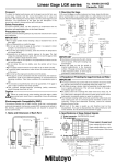
1. A range of models available
The gage heads described offer five measuring ranges (5, 10, 25, 50 and 100mm) and six resolution
settings (0.01, 0.005, 0.001, 0.0005, 0.0001 and 0.00001mm) to enable the choice of gage to be closely
matched to the application requirements. Various output modes are also available, including differential
square-wave, Digimatic code (SPC) and sine wave.
2. Suitable for production line use
The gage heads offer superb durability and environmental resistance, making them ideal for in-line
measurements. Durability is ensured by strong construction and linear ball bearings in the slider unit
(except for models LGS and LGB), which are designed to last up to 10 million vertical spindle strokes
(according to Mitutoyo’s internal tests). Moreover, excellent dust/water protection (IP66) is provided for
effective use in severe in-line environments (model LGF and others).
Suitable for in-line use
3. High-density design
The slender design of the standard gages enables installation in confined spaces or where the application
demands close-pitched gaging. Slim-line models with outside diameters of 8mm are also available for
measurements in spaces of 10mm or less. Gages come in two different cable arrangements — vertical
and horizontal — to suit the type of fixture used.
4. Simple mounting
All gages can be mounted by the plain section of the stem using the split-clamp method. Alternatively,
some gages are threaded at the bottom and so can also be installed simply by drilling a hole of the
appropriate size in a fixture and clamping the gage with a plain nut or by using a thrust stem (see page
33). Gages with a stem threaded at the top can be mounted using a thrust stem as an alternative to the
split clamp.
5. A choice of output format
Suitable for close-pitched applications
The gage head display units offer a range of output formats to best match the application requirements:
I/O, BCD, RS-232C and Digimatic code (SPC) types are available. The EH/EV counter has an RS link
function to be connected with multiple counters for multi-gage measurement (see page 36).
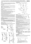
Measurement principle
The gage heads mainly use transmissiontype photoelectric linear encoders, as
shown below. In this type, the light source
(LED) and the detector element (photodiode)
face each other with the main scale
and index scale (20μm pitch) positioned
between them.
As the scale moves with respect to the
detector, the intensity of the light passing
Output
through the window in the index scale
varies constantly. At this time, two
synchronized sine-wave signals having a
relative 90-degree phase difference are
output. These signals are then amplified
and split electrically (with additional
waveforms inserted) and output as 0.1µm,
0.5µm, 1µm or 5µm square-wave signals.
-AIN¬SCALE
The gage head processes internally
detected signals and outputs square-wave
signals as shown below. These operating
signals, which are square waves having
a phase difference of 90 degrees, are
equivalent to RS-422A signals, allowing
for the independent use of the gage head.
However, certain models (LGD and LGS),
do not output square-wave signals but
generate Digimatic code (SPC) output in
order to identify the measurement position.
0HOTODIODE
0HASE0!
0HASE!
3IGNAL¬PITCH
«M
,%$
)NDEX¬SCALE
0HASE0"
0HASE"
«M
#ONDENSER¬LENS
-EASURING¬PITCH
Contents
Traceability System to National Standards
Applications
Gage Head Overview
Display Unit Overview
4-5
6-9
10 - 12
13
Gage Heads
14
15
16
17
LGK
LGF
LGF
LGF
LGS
LGD
LGB
LGB
Display Units
Slim Type
Standard Type
with Origin Point Mark
0.1µm Resolution Type
Absolute Type
Absolute Type
Extremely Compact ø9.5mm Stem Type
Extremely Compact ø8mm Stem Type
18
19
20
21
LG Long Stroke Type
LGM Motor-drive, Long Stroke Type
Laser Hologage High-resolution Type
Litematic Head and Litematic
22
23
24
25
Signal ID-C Absolute Type
Output Signal Specifications
Air Drive Unit
Gage Head Mounting Fixtures
Optional Accessories
26 - 27
28 - 30
31
32 - 33
34 - 36
System Connection and Comparison of Counter Functions
SENSORPAK
EC Counter
EG Counter
37
38
39
40 - 41
EB Counter
EH Counter
D-EV Display Unit
EV Counter
42 - 45
46 - 50
50
51 - 55
Optional Accessories
Quick Guide to Precision Measurement
56 - 57
58 - 61
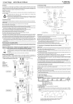
Traceability System to National Standards
Traceability System of Length Standard
Traceability of
temperature field
Traceability of length field
National Metrology Institute of Japan / National Institute of Advanced Industrial Science and Technology (NMIJ/AIST)
633nm Iodine Stabilized He-Ne Laser <National (Primary) Standard>
NMIJ/AIST
Temperature
fixed points
<National (Primary)
Standard>
Mitutoyo Metrology Calibration Center (JCSS Accredited Cal. Lab. No.0031)
633nm Iodine Stabilized He-Ne Laser <Secondary Standard>
Mitutoyo Miyazaki Plant
(JCSS Accredited Cal. Lab. No.0030)
633nm Stabilized He-Ne Laser
<Laboratory Reference Standard>
Mitutoyo Utsunomiya
Calibration Center
(JCSS Accredited Cal.Lab. No.0078)
633nm Stabilized He-Ne Laser
<Laboratory Reference Standard>
Mitutoyo Metrology
Calibration Center
(JCSS Accredited Cal.Lab. No.0031)
633nm Stabilized He-Ne Laser
JCSS Accredited Cal. Lab.
Stabilized He-Ne Laser
<Laboratory Reference Standard>
JCSS Accredited
Cal. Lab.
Temperature fixed point /
Platinum resistance
thermometer
<Secondary Standard>
Mitutoyo Utsunomiya
Calibration Center
(JCSS Accredited Cal.Lab. No.0078)
Standard Gauge Block
<Laboratory Reference Standard>
Mitutoyo Techno Service
Business Division (JCSS
Accredited Cal. Lab. No.0186)
Standard Gauge Block /
Step Gage
Working
Standard
Measuring
Instrument
Step Gage
Coordinate
Measuring Machine
Mitutoyo Utsunomiya
Calibration Center (JCSS
Accredited Cal. Lab. No.0078)
Standard Gauge Block /
Micrometer Standard /
Step Gage
Gauge Block
Scale unit
Iodine Absorption Stabilized He-Ne Laser used
for calibrating length standards
(Metrology Calibration Center)
Ring Gage
Precision
Sensors
Mitutoyo Metrology
Calibration Center
(JCSS Accredited
Cal. Lab. No.0031)
Temperature fixed point
(Triple point of water) /
Platinum resistance
thermometer
<Laboratory
Reference Standard>
Mitutoyo Hiroshima
Calibration Center (JCSS
Accredited Cal. Lab. No.0109)
Standard Gauge Block /
Micrometer Standard /
Step Gage
<Laboratory Reference Standard>
Dial Gage
Tester
Measuring
Tool
Standard
Scale
Form
Measuring Machine
Laser Length
Measuring
Machine
Vision
Measuring Machine
Interferometer used for calibrating gauge blocks
(Miyazaki Plant)
JEMIC
Temperature fixed point
<National (Sub-Primary)
Standard>
Optical
Flat/Parallel
Optical
Measuring
Machine
Thermometer
Interferometer used for calibrating linear scales
(Metrology Calibration Center)
Mitutoyo Group Accredited Calibration Laboratories
National metrology
institute
Accreditation body
APLAC
<MRA>
Japan
NMIJ/
AIST
Accredited calibration laboratory
Mitutoyo Miyazaki Plant No.0030
Mitutoyo Metrology Cal.Center No.0031*1
JCSS
IAJapan/NITE
Mitutoyo Utsunomiya Cal.Center No.0078
Mitutoyo Hiroshima Cal.Center No.0109*2
Mitutoyo Kawasaki Cal.Center (Force) No.0086
ILAC
<MRA>
Singapore
Indonesia
Thailand
Vietnam
Mitutoyo Techno Service Business Division No.0186
Mitutoyo Asia Pacific No.LA-1996-0102-C*2
Mitutoyo Asia Pacific (Indonesia office) No.LA-1996-0102-C-1*2
SACSINGLAS
SPRING
Mitutoyo Thailand No.LA-1996-0102-C-2*2
Mitutoyo Thailand (Cholburi Branch) No.LA-1996-0102-C-2-1*2
Mitutoyo Asia Pacific (Ho Chi Minh office) No.LA-1996-0102-C-4
Malaysia
SIRIM
DSM
Mitutoyo Malaysia No.SAMM152*2
Taiwan
NML
TAF
Mitutoyo Taiwan No.0336*2
India
NPLI
NABL
Mitutoyo South Asia No.C-0349*2
USA
NIST
A2LA
Canada
NRCINMS
CLAS/
SCC
Mexico CENAM
EMA
EA
<MRA>
Mitutoyo America (Elk Grove) No.0750.01*1
Mitutoyo America Field Service No.1643.01*2
Mitutoyo Canada No.2003-05*2
Mitutoyo Mexicana (Length) No.D-45
Mitutoyo Mexicana (Hardness) No.DZA-10
Mitutoyo UK No.0332*2
UK
NPL
The Netherlands
NMi
RvA
Mitutoyo Netherland No.K 086
Germany
PTB
DKD
Mitutoyo Messgeräte No.DKD-K-14501
Switzerland
METAS
SAS
Mitutoyo Schweiz No.SCS074
Italy
IMGC
SIT
Mitutoyo Italiana No.107
SP
SWEDAC
Mitutoyo Scandinavia No.1794
Sweden
Brazil INMETRO
Argentina
INTI
UKAS
RBC
Mitutoyo Sul Americana No.031*2
OAA
Mitutoyo Argentina No.LC 010
AIST........ National Institute of Advanced Industrial
Science and Technology
NMIJ....... National Metrology Institute of Japan
JCSS ....... Japan Calibration Service System
NITE........ National Institute of Technology and Evaluation
IAJapan ... International Accreditation Japan
SPRING ... Standards, Productivity and Innovation Board
SAC........ Singapore Accreditation Council
NML ....... National Measurement Laboratory
TAF......... Taiwan Accreditation Foundation
SIRIM...... Standards and Industrial Research Institute of
Malaysia
DSM ....... Department of Standards Malaysia
NIST........ National Institute of Standards and Technology
A2LA ...... American Association for Laboratory Accreditation
NRC-INMS.. National Research Council of Canada-Institute
for National Measurement Standards
CLAS ...... Calibration Laboratory Assessment Service
SCC........ Standards Council of Canada
CENAM... Centro Nacional de Metrología
EMA ....... Entidad Mexicana de Acreditación, a.c.
NPL......... National Physical Laboratory
UKAS...... United Kingdom Accreditation Service
NMi ........ Nederlands Meetinstituut
RvA ........ Raad voor Accreditatie
PTB......... Physikalisch-Technische Bundesanstalt
DKD ....... Deutscher Kalibrierdienst
METAS ... The Swiss Federal Office of Metrology and
Accreditation
SAS ........ Swiss Accreditation Service
IMGC ..... Istituto di Metrologia “GUSTAVO COLONNETTI”
SIT .......... Servizio di Taratura in Italia
SP........... Swedish National Testing and Research Institute
SWEDAC ... Swedish Board for Accreditation and
Conformity Assessment
INMETRO... Instituto Nacional de Metrologia Normalização
e Qualidade Industrial
RBC ........ Rede Brasileira de Calibração
INTI......... Instituto Nacional de Tecnologia Industrial
OAA ....... Organismo Argentino de Acreditaci
NPL......... National Physical Laboratory
NPLI........ National Physical Laboratory of India
NABL ...... National Accreditation Board for Testing and
.....International Laboratory Accreditation Cooperation
(ILAC) ....Asia-Pacific Laboratory Accreditation Cooperation
(APLAC)
(EA) ........European Accreditation Cooperation
(MRA).....Mutual Recognition Arrangement
# ............ Accreditation No.
No mark is only length
*1 Length and Temperature
*2 Length and Hardness
Mitutoyo has 27 accredited calibration laboratories posted worldwide as illustrated above, where each of the labs has
established and implemented traceability of their reference standards through calibration to nationally or internationally
recognized standards. It is this traceability system that enables Mitutoyo to contribute to industries worldwide in helping
customers implement the base for their quality management and quality assurance program.
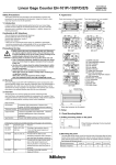
Applications
Multipoint measurement of automobile doors
Measurement of aircraft fuselage distortion
Gage heads (LGS with EV counter) can be used to perform multi-point
measurements for automobile doors and evaluate errors against the
specified tolerances. When there are many points to measure, the use of
the LGS gage provides higher cost-effectiveness.
Gage heads (LGD with EV counter) can be used to help measure changes
in stress generated in an aircraft fuselage. For the very large workpiece,
the use of an absolute type gage head is recommended, since the master
settings then need to be done just once.
Measurement of hydraulic coupling dimensions
Multipoint measurement of turbine blades
Gage heads (LGF with EH counter) can be used to measure the outside
diameters and thicknesses of hydraulic couplings used in mechanical
diggers. The EH counter allows for the calculation of sums and differences
between two gages.
Gage heads (LGB with EV counter) can be used to perform multi-point
measurements of gas turbine blades.
Measuring outside
diameter and thickness
Measurement of camshaft displacement
Built-in sensor for inside diameter measurement
tools
Gage heads (LGF with EH counter) can be used to measure camshaft lift.
The EH counter is easily installed in the equipment panel.
Measuring
displacement
A gage head (LGF with EH counter) can be used to measure inside
diameters.
When strong sideways force
would otherwise be exerted on
the gage, as in this application,
take measurements indirectly
using a fixture in order to avoid
subjecting the gage to excessive
loads or wear.
Multipoint measurement of wheel hubs
Inspecting rivets
Gage heads (LGF with EH counter) can be used to inspect a wheel hub for
compliance with runout limits.
A gage head (LGD with EG counter) can be used to inspect the condition of
fixing of a rivet or bolt. Inspection of parts press-fitted is also done in the
same way.
Built-in sensor for machine tools
Measurement of sash rail warp
A gage head (LGM with EH counter) can be used to measure a workpiece
which has been machined on a surface grinder.
Gage heads (LGF with EV counter) can be used to measurethe warp of sash
rails.
Measurement of pipe wall thickness/outside
diameter
Measurement of elevator drive-rail deflection
A gage head (LGF with EB counter) can be used to measure deflection in the
drive rail of an elevator. Measured data can be output from the EB counter
to a personal computer in order to plot the displacement.
A gage head (LGF with EH counter) can be used to measure the wall
thickness or outside diameter of a pipe.
Pipe wall thickness
measurement
Deflection data
tolerance judgement
Outside diameter
measurement
Roller to hold workpiece
Roller to support workpiece
When strong sideways force would
otherwise be exerted on the gage, as in this
application, take measurements indirectly
using a fixture in order to avoid subjecting
the gage to excessive loads or wear.
Plotted deflection
data
Measurement of caulking height
Measurement of cylindrical pin displacement
A gage head (LGF with EB counter) can be used to measure the caulking
height of a crimp contact, etc.
Gage heads (LGB with EH counter) can be used to measure the
displacement of tape-winding capstan pins in cassette recorders. The EH
counter is capable of calculating sums and differences between two gages.
X-direction :
Measuring pin
displacement
Y-direction :
Measuring pin
displacement
Measurement of bridge-support joint
Multipoint measurement on parabolic antenna
Gage heads (LGD with EG counter) can be used to measure the
displacement of a bridge-support joint. Since this measurement is performed
intermittently over a long period of time, use an absolute-type gage head
that requires power only during measurement.
Gage heads (LGB with EV counter) can be used to perform multi-point
measurements on a parabolic antenna surface.
Measuring
displacement
Applications
Multipoint measurement of VTR chassis
Flatness measurement of tape cassette
Gage heads (LGF with EV counter) can be used to measure VTR components
at several points.
Gage heads (LGK with EV counter) can be used to perform flatness
measurement on a tape cassette surface.
Measurement of hub runout for floppy disks
Contour measurement of CRT panel
The gage head (LGB with EH counter) can be used to measure the runout of
the disk's hub.
Gage heads (LGS with EV counter) can be used to measure the surface
contour of CRT panels.
Measuring
the run-out
When strong sideways force would
otherwise be exerted on the gage, as in this
application, take measurements indirectly
using a fixture in order to avoid subjecting
the gage to excessive loads or wear.
Parallelism measurement of copying machine
parts
Multipoint measurement on copying machine
chassis
Gage heads (LGD with EV counter) can be used to measure the parallelism
of copying machine parts.
Gage heads (LGS with EV counter) can be used to perform multi-point
measurement on a copying machine chassis. In the case of large workpieces
an absolute type that eliminates the necessity of setting a master workpiece
will be useful.
Run-out measurement of motor shaft
Sorting of parts
Gage heads (LGF with EH counter) can be used to measure the radial
and axial run-out of motor shafts. The EH counter can display both
measurements simultaneously.
A gage head (LGF with EB counter) can be used to sort parts by size. The
EB counter can divide the dimension into seven steps and output the signal
for sorting.
When strong sideways force
would otherwise be exerted on
the gage, as in this application,
take measurements indirectly
using a fixture in order to avoid
subjecting the gage to excessive
loads or wear.
Multipoint measurement of LCD panel
X-Y stage positioning
Gage heads (LGF with EH counter) can be used to measure distortion of
LCD panels.
Gage heads (LGF with EH counter) can be used to position a precision stage.
Height measurement of cell
Built-in sensor for material testing machines
A gage head (LGF with EH counter) can be used to measure the height of
built-in dry cells.
A gage head (LG with EH counter) can be used to measure the extension of
a specimen during a tensile test.
Extension
measurement
Deformation measurement of bathtub
Incorporation into auto-measurement machine
Gage heads (LGD with EV counter) can be used to measure the deformation
of bathtubs. An origin setting when first mounting the gage head can
eliminate the need for subsequent resetting with a standard.
Gage heads (LGF with EH counter) can be incorporated into the automeasurement unit for outside diameter and/or height measurement.
Built-in sensor for tablet forming machine
Incorporation into vision measuring machine /
microscope
A gage head (LGF with EH counter) can be used to measure the stroke of a
tablet forming machine.
A gage head (LGF with EH counter) can be incorporated into a measuring
machine for height measurement.
Gage Head Overview
Laser Hologage
•0.01µm resolution
•Sine wave output
•ø15mm plain stem
Laser Hologage
Range: 10mm / .4”
•0.1µm resolution
•Square wave out put
•ø15mm plain stem
Page 24
Compatible display unit
EG-101P
A low measuring force
model is available
•1µm resolution
•Square wave out put
•ø9.5mm stem
Page 24
Compatible display unit
EH-102S
LGB series
Range: 10mm / .4”
EH-101P
EH-102P
LGB series
Range: 5mm / .2”
Range: 5mm / .2”
•0.1 / 1µm resolution
•Square wave output
•ø9.5 / ø8mm stem
Page 20
Compatible display unit
Page 20
Compatible display unit
EG-101P
EB-11P
EG-101P
EB-11P
EH-101P
EH-102P
EH-101P
EH-102P
EV-16P
A low measuring force
model is available
Page 21
ø8mm stem
ø9.5mm stem
With stem
clamp nut
EV-16P
LGB series
Range: 10mm / .4”
•1µm resolution
•Square wave output
•ø9.5 / ø8mm stem
Compatible display unit
EG-101P
EB-11P
EH-101P
EH-102P
Page 20
Page 21
ø8mm stem
ø9.5mm stem
With stem clamp nut
LGK series
ø8mm stem
ø9.5mm stem
With stem clamp nut
High accuracy, low measuring force and sine
wave output models available
EV-16P
Page 20
Page 21
With pneumatic cylinder
Range: 10mm / .4”
•0.1 / 0.5 / 1µm
resolution
•Square wave output
•ø8mm stem
Page 14
Page 14
Page 14
Compatible display unit
EG-101P
EB-11P
EH-101P
EH-102P
0.1µm / 4µinch
0.5µm / .00002”
1µm / .00004”
EV-16P
LG series
LGM series
Range: 100mm / 4”
•0.1 / 1µm resolution
•Square wave output
•ø20mm stem
Range: 100mm / 4”
•0.1 / 1µm resolution
•Square wave output
•ø20mm stem
•Motor-drive
operation
Page 22
Compatible display unit
Page 23
Motor-drive unit
Compatible display unit
EG-101P
EB-11P
EG-101P
EB-11P
EH-101P
EH-102P
EH-101P
EH-102P
EV-16P
EV-16P
10
LGF series
Range: 10mm / .4”
Range: 25mm / 1”
Range: 50mm / 2”
•0.5 / 1µm resolution
•Square wave output
•ø8mm / ø15mm stem
Compatible display unit
EG-101P
EB-11P
EH-101P
EH-102P
EV-16P
ø8mm stem
0.5µm / .00002”
ø15mm stem
1µm / .00004”
Page 15
0.5µm / .00002”
1µm / .00004”
ø15mm stem
Page 15
Page 15
0.5µm / .00002”
LGF series
Range: 10mm / .4”
Range: 25mm / 1”
1µm / .00004”
Range: 50mm / 2”
•0.5 / 1µm resolution
•Square wave output
•ø8mm / ø15mm stem
•With origin point
mark
Compatible display unit
EG-101Z
EB-11Z
EH-102Z
EV-16Z
ø8mm stem
0.5µm / .00002”
ø15mm stem
1µm / .00004”
Page 16
0.5µm / .00002”
1µm / .00004”
ø15mm stem
Page 16
LGF series
Range: 10mm / .4”
Page 16
Range: 25mm / 1”
•0.1µm resolution
•Square wave output
•ø8mm / ø15mm stem
0.5µm / .00002”
1µm / .00004”
Compatible display unit
EG-101P
EB-11P
EH-101P
EH-102P
ø8mm stem
ø15mm stem
Page 17
EV-16P
Page 17
LGF series
Range: 25mm / 1”
Range: 50mm / 2”
•5µm resolution
•Square wave output
•ø15mm stem
Compatible display unit
EG-101P
EB-11P
EH-101P
EH-102P
EV-16P
Page 15
11
Page 15
Gage Head Overview
LGD series
Range: 10mm / .4”
Range: 25mm / 1”
Range: 50mm / 2”
•0.01mm resolution
•Digimatic output
•Absolute linear encoder
•ø8mm / ø15mm stem
Compatible display unit
EC-101D
EG-101D
EB-11D
EH-102D
Page 19
EV-16D
ø8mm stem
LGS series
Page 19
Range: 12.7mm / .5”
ø15mm stem
•0.01mm resolution
•Digimatic output
•Absolute linear encoder
•ø8mm stem
Page 19
Compatible display unit
EC-101D
EG-101D
EB-11D
EH-102D
ø15mm stem
Page 18
EV-16D
Signal ID-C
Range: 12.7mm / .5”
•0.001mm resolution
•Digimatic output
•Absolute linear encoder
•ø8mm stem
Compatible display unit
EC-101D
EG-101D
EB-11D
EH-102D
EV-16D
Page 26
System Connections
0.5 / 1 / 5µm gage head
LGK
LG
LGF
LGM
LGB
0.1µm gage head
LGK
LG
LGF
LGM
LGB
Laser Hologage*
*EB-11P and EV-16P are not applicable.
Gage head with Origin Point Mark
LGF
Absolute type gage head
LGS
LGD
EG-101P
EB-11P
EH-101P
EH-102P
EV-16P
EG-101Z
EB-11Z
EH-102Z
EV-16Z
EC-101D
EG-101D
EB-11D
EH-102D
0.01µm gage head
Laser Hologage
EV-16D
EH-102S
Applicable gages Function Output
3/5-stage Limit, BCD
3/5-stage limit, 7ch limit, Serial BCD, Simple analog
3/5-stage limit, RS-232C, Simple BCD, Simple analog
3/5-stage limit, Segment, Parallel BCD, RS-232C
Programmable Controller
3/5-stage limit, BCD
3/5-stage limit, 7ch limit, Serial BCD, Simple analog
3/5-stage limit, RS-232C, Simple BCD, Simple analog
3/5-stage limit, Segment, Parallel BCD, RS-232C
3/5-stage limit, Digimatic
Personal computer
3/5-stage limit, BCD
3/5-stage limit, 7ch limit, Serial BCD, Simple analog
3/5-stage limit, RS-232C, Simple BCD, Simple analog
3/5-stage limit, Segment, Parallel BCD, RS-232C
3/5-stage limit, RS-232C, Simple BCD, Simple analog
12
Digimatic Mini-processor DP-1VR
Display Unit Overview
EC counter
For Digimatic output gage heads
Single function type
Page 39
EG counter
EC-101D
For Digimatic output gage heads
Single function type
For square wave output gage
heads
For square wave output gage
heads with origin point mark
Page 40
EG-101P
EG-101D
EB counter
For Digimatic output gage heads
Multi-function type
For square wave output gage
heads
EG-101Z
For square wave output gage
heads with origin point mark
Page 42
EB-11P
EB-11D
EH counter
For Digimatic output gage heads
Multi-function type
For square wave output gage
heads (1-axis / 2-axis)
EB-11Z
For square wave output gage
heads with origin point mark
Page 46
EH-101P
EH-102D
EH-102Z
For Sine wave output gage heads
EH-102P
EH-102S
EV counter
For Digimatic output gage heads
Multi-function type
for multi-gage system
For square wave output gage
heads
For square wave output gage
heads with origin point mark
Page 51
EV-16D
EV-16P
13
EV-16Z
Gage
Heads
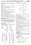
LGK
Slim Type
Unit: mm
Connector
Connecting cable
82.7
10mm range, 0.1 / 0.5 / 1µm resolution, Differential square-wave output
FEATURES
•A slim-body model which has succeeded the proven LGF series in terms of vibration- and impactresistance. The sectional area is only a 1/5 compared to that of the LGF-110L model.
•Provides a resolution of 0.1 / 0.5 / 1μm, whichever is selectable.
RM12BPE-6PH
(HIROSE)
20.4
30
Dimensions
Unit: mm
542-158: 0.1µm resolution model
542-157: 0.5µm resolution model
542-156: 1µm resolution model
ø12
ø12
ø12
125.5
73.1
6.5
0
ø8-0.009
10.6 or longer (stroke)
10.6 or longer (stroke)
14
125.5
6.5
125.5
6.5
Attachment thread for thrust stem
M9.5X0.5
14
0
ø8-0.009
10.6 or longer (stroke)
0
ø8-0.009
Attachment thread for thrust stem
M9.5X0.5
14
Attachment thread for thrust stem
M9.5X0.5
Connecting cable: 2m
73.1
Connecting cable: 2m
73.1
Connecting cable: 2m
SPECIFICATIONS
Order No.
Measuring range
Resolution
Accuracy (20°C)*1
Spindle DOWN
Horizontal
Spindle UP
Position-detection sensor
Max. response speed*2
Measuring force
Output signal
Signal pitch
Mass
Dust/Water protection level*3
Contact point
Stem size
Bearing type
Connecting cable length
Connector
Operating environment
Standard accessory
Optional accessories
542-158
542-157
10mm
0.0005mm
0.0001mm
(0.8+L/50)µm (L=mm)
542-156
0.001mm
(1.5+L/50)µm (L=mm)
Approx. 0.8N or less
Approx. 0.75N or less
Approx. 0.7N or less
Transmission-type photoelectric linear encoder*4
400mm/s
1500mm/sec
90° phase difference, differential square wave (RS-422A equivalent); minimum edge intervals 200ns for 0.1µm model,
250ns for 0.5µm model, and 500ns for 1µm model
0.4µm
2µm
4µm
250g
IP66
ø3mm carbide (mounting: M2.5x0.45), 901312
ø8mm
Linear ball bearing*5
2m
Plug used: RM12BPE-6PH (HIROSE), Compatible socket: RM12BRD-6S (HIROSE)
0°C to 40°C (20%RH to 80%RH, without condensation)
Wrench for contact point (538610)
238772: 10mm rubber boot (spare)
02ADB680: Thrust stem and wrench set
02ADB681: Thrust stem
02ADB683: Thrust stem wrench
*1: Excluding quantizing error of ±1 count.
*2: When the travel speed of spindle exceeds 1500mm/s (400mm/s for the case of 0.1µm model), an alarm signal will be output and an error display will result if any Mitutoyo counter is used. For the method of making use of alarm
signals where any Mitutoyo counter is not used refer to Page 30. However, note that the spindle’s free travel may exceed the given speed limit to cause an error if the contact point is released quickly after it has been pressed in,
depending on the amount of over-travel produced.
*3: IP level is the standard of protection against the ingress of solids/foreign matter and water. This may not be applicable for liquids other than water .
*4: Patent registered (Japan, U.S.A., Germany, U.K.)
*5: Patent registered (Japan)
14
Gage
Heads
LGF
Standard Type
Connector
Unit: mm
41
10 / 25 / 50mm range, 0.5 / 1 / 5µm resolution, Differential square-wave output
ø18
ø11.8
FEATURES
•Excellent protection against dust ingress and water splash (IP66) in harsh shop-floor environments.
•Uses linear stroke ball bearings on the spindle movement for resistance to external shock and vibration.
•Thrust Stem with a clamp nut is optional.
Dimensions
Unit: mm
542-173: 0.5µm resolution, 50mm range model
542-163: 1µm resolution, 50mm range model
542-613: 5µm resolution, 50mm range model
542-171: 0.5µm resolution, 10mm range model
542-161: 1µm resolution, 10mm range model
542-172: 0.5µm resolution, 25mm range model
542-162: 1µm resolution, 25mm range model
542-612: 5µm resolution, 25mm range model
Clamp nut
02ADB692
M18×1
(24.2)
Clamp nut
02ADB692
M18×1
174
(316)
29.6
6
M14×0.5
Attachment thread
for thrust stem
142
93.6 6.5
13.8
0
ø15-0.015
0
ø18 -0.018
21
21
(24.2)
8.6
51.5 or longer
(stroke)
22
0
ø15 -0.015
M14×0.5
Attachment thread
for thrust stem
Dimensions with a thrust stem installed
124.9
4.5
18.5
9
5
8.6
0
ø18 -0.018
Thrust stem
02ADN371
(208.3)
Thrust stem
02ADN371
Connecting
cable
2m
114.7
Connecting cable
2m
26 or longer
(stroke)
75.7
6.9(129.5)
46.9 14
61.7
34
5
Clamp nut
02ADB682
M9.5×0.5
12.3
56.1
41
20.6
0.6 20
(screw top
height)
Dimensions with a thrust stem installed
84.1
4.5
9 18.5
12
(13.8)
10.6 or longer
(stroke)
0
ø9.5-0.015
6
M9.5×0.5
Attachment thread
0
for thrust stem ø8-0.009
61.7
34
30.7
41
Connecting cable
2m
61.5
34
17.3
Dimensions with a thrust stem installed
45.9 5
14.5
9.5
4
Thrust stem
02ADB681
20.6
0.6 20
(screw top
height)
ø18
ø18
15.4
0.6 14.8
(screw top
height)
41
ø18
13.8
SPECIFICATIONS
Order No.
Measuring range
Resolution
Accuracy (20°C)*1
Spindle DOWN
Measuring
Horizontal
force
Spindle UP
Position-detection method
Max. response speed*2
Output signal
Signal pitch
Mass
Dust/water protection*3
Contact point
Stem size
Bearing type
Connecting cable length
Connector
Operating environment
Standard accessory
Optional accessories
542-171
542-161
542-172
542-162
542-612
542-173
542-163
542-613
25mm
50mm
0.0005mm
0.001mm
0.0005mm
0.001mm
0.005mm
0.0005mm
0.001mm
0.005mm
(1.5+L/50)µm for 0.5µm / 1µm model, (7.5+L/50)µm for 5µm model (L=mm)
1.2N or less
4.6N or less
5.7N or less
1.1N or less
4.3N or less
5.3N or less
1.0N or less
4.0N or less
4.9N or less
Transmission-type photoelectric linear encoder*4
1500mm/sec
90° phase difference, differential square wave (RS-422A equivalent);
minimum edge intervals 250ns for 0.5µm model, 500ns for 1µm model, 1000ns for 5µm model,
4µm
2µm
4µm
2µm
4µm
2µm
250g
300g
400g
IP66
ø3mm carbide (mounting: M2.5x0.45) 901312
ø8mm
ø15mm
Linear ball bearing*5
2m
Plug used: RM12BPE-6PH (HIROSE), Compatible socket: RM12BRD-6S (HIROSE)
0°C to 40°C (20%RH to 80%RH, without condensation)
Wrench for contact point (538610)
Wrench for contact point (210187)
962504 25mm rubber boot (spare)
962505 50mm rubber boot (spare)
238772: 10mm rubber boot (spare)
02ADB680: Thrust stem and wrench set
02ADN370: Thrust stem and wrench set
02ADB683: Thrust stem rench
02ADB693: Thrust stem wrench
10mm
*1: Excluding quantizing error of ±1 count.
*2: When the travel speed of spindle exceeds 1500mm/s (400mm/s for the case of 0.1µm model), an alarm signal will be output and an error display will result if any Mitutoyo counter is used. For the method of making use of alarm
signals where any Mitutoyo counter is not used refer to Page 30. However, note that the spindle’s free travel may exceed the given speed limit to cause an error if the contact point is released quickly after it has been pressed in,
depending on the amount of over-travel produced.
*3: IP level is the standard of protection against the ingress of solids/foreign matter and water. This may not be applicable for liquids other than water .
*4: Patent registered (Japan, U.S.A., Germany, U.K.)
*5: Patent registered (Japan)
15
with Origin Point Mark
Connector
Unit: mm
Sleeve
ø16.7
10 / 25 / 50mm range, 0.5 / 1µm resolution, Differential square-wave output
FEATURES
34.0
•The origin point signal output function enables the measuring system to be reset easily when this gage is
incorporated in a machine tool. This function helps boost productivity by drastically reducing reset time,
since the origin position can be recaptured very easily even when lost due to over-speed errors, etc.
Dimensions
ø6.2
LGF
542-176: 0.5µm resolution, 50mm range model
542-166: 1µm resolution, 50mm range model
Unit: mm
ø16.7
542-175: 0.5µm resolution, 25mm range model
542-165: 1µm resolution, 25mm range model
34
174
(316)
0
ø15-0.015
M14×0.5
Attachment thread
for thrust stem
(24.2)
29.6
114.7
22
13.8
0
ø18-0.018
Clamp nut
02ADN371
M18×1
51.5 or longer
(stroke)
Clamp nut
02ADB692
M18×1
8.6
13.8
21
21
(24.2)
Thrust stem
02ADN371
Dimensions with a thrust stem installed
124.9
4.5
9 18.5
5
M14×0.5
Attachment thread
for thrust stem
6.5
93.6
0
ø15 -0.015
0
ø18-0.018
(208.3)
8.6
26 or longer
(stroke)
75.7
6.9(129.5)
14
46.9
12.3
34.0
Connecting
cable
2m
Connecting
cable
2m
Thrust stem
02ADN371
Dimensions with a thrust stem installed
4.5
84.1
18.5
9
5
12
(13.8) Clamp nut
02ADB682
M9.5×0.5
10.6 or longer
(stroke)
ø9.5
0
-0.015
Connecting
cable
6
2m
M9.5×0.5
Attachment thread
0
for thrust stem ø8-0.009
61.7
34
30.7
34
20.6
0.6 20
(screw top
height)
61.5
34
17.3
Dimensions with a thrust stem installed
45.9 5
9.5 14.5
4
15.4
0.6 14.8
(screw top
height)
61.7
34
56.1
ø16.7
ø16.7
Thrust stem
02ADB681
20.6
0.6 20
(screw top
height)
6
542-174: 0.5µm resolution, 10mm range model
542-164: 1µm resolution, 10mm range model
34
ø16.7
142
Gage
Heads
SPECIFICATIONS
Order No.
Measuring range
Resolution
Accuracy (20°C)*1
Spindle DOWN
Horizontal
Spindle UP
Position-detection method
Origin point
Repeatability of origin point (20°C)
Max. response speed*2
Measuring force
Output signal
Signal pitch
Mass
Dust/water protection*3
Resistance to impact
Contact point
Stem size
Bearing type
Connecting cable length
Connector
Operating environment
Standard accessory
Optional accessories
542-174
542-164
542-175
10mm
0.0005mm
542-165
25mm
542-176
542-166
50mm
0.001mm
0.0005mm
0.001mm
0.0005mm
0.001mm
(1.5+L/50)µm (L=mm)
1.2N or less
4.6N or less
5.7N or less
1.1N or less
4.3N or less
5.3N or less
1.0N or less
4.0N or less
4.9N or less
Transmission-type photoelectric linear encoder*4
Approx. 3mm from initial contact with tip
Approx. 5mm from initial contact with tip
≤0.5µm (passing speed less than 300mm/s in the same direction)
1500mm/s
90° phase difference, differential square wave (RS-422A equivalent); minimum edge intervals 500ns for 1µm model,
250ns for 0.5µm model
2µm
4µm
2µm
4µm
2µm
4µm
260g
300g
400g
IP66
1000m/s2, 11ms (IEC68-2-27)
ø3mm carbide (mounting: M2.5x0.45), 901312
ø8mm
ø15mm
Linear ball bearing*3
2m
Plug used: PRC05-P8M (TAJIMI), Applicable receptacle: PRC05-R8F (TAJIMI)
0°C to 40°C (20%RH to 80%RH, without condensation)
Wrench for contact point (538610)
Wrench for contact point (210187)
962504: 25mm rubber boot (spare)
962505: 50mm rubber boot (spare)
238772: 10mm rubber boot (spare)
02ADB680: Thrust stem and wrench set
02ADN370: Thrust stem and wrench set
02ADB683: Thrust stem wrench
02ADB693: Thrust stem wrench
*1: Excluding quantizing error of ±1 count.
*2: When the travel speed of spindle exceeds 1500mm/s (400mm/s for the case of 0.1µm model), an alarm signal will be output and an error display will result if any Mitutoyo counter is used. For the method of making use of alarm
signals where any Mitutoyo counter is not used refer to Page 30. However, note that the spindle’s free travel may exceed the given speed limit to cause an error if the contact point is released quickly after it has been pressed in,
depending on the amount of over-travel produced.
*3: IP level is the standard of protection against the ingress of solids/foreign matter and water. This may not be applicable for liquids other than water .
*4: Patent registered (Japan, U.S.A., Germany, U.K.)
*5: Patent registered (Japan)
16
Gage
Heads
LGF
0.1µm Resolution Type
Connector
30
10 / 25mm range, 0.1µm resolution, Differential square-wave output
Unit: mm
82.7
FEATURES
20.4
•Excellent protection against dust ingress and water splash (IP66) in harsh shop-floor environments.
•Uses linear stroke ball bearings on the spindle movement for resistance to external shock and vibration.
•Thrust Stem with clamp nut is optional.
Dimensions
82.7
Unit: mm
542-181
20.4
30
542-182
0.6
(screw top
height)
30
61.7
20
34
30.7
82.7
20.6
20.4
17.3
12.3
M18×1
114.7
M14×0.5
Attachment thread
for thrust stem
(208.3)
22
13.8
(24.2)
21
12
6.5
Clamp nut
02ADB692
93.6
0
ø15 -0.015
ø18
26 or longer
(stroke)
75.7
ø8
0
-0.009
6.9(129.5)
M9.5×0.5
Attachment thread
for thrust stem
Thrust stem
02ADN371
Dimensions with a thrust stem installed
4.5
84.1
18.5
9
5
M9.5×0.5
(13.8)
Connecting cable
2m
14
Clamp nut
02ADB682
6
8.6
46.9
0
ø9.5 -0.015
34
10.6 or longer
(stroke)
Dimensions with a thrust stem installed
5
45.9
14.5
9.5
4
Thrust stem
02ADB681
Connecting
cable
2m
61.5
15.4
0.6 14.8
(screw top
height)
SPECIFICATIONS
Order No.
Measuring range
Resolution
Accuracy (20°C)*1
Accuracy (20°C)
Spindle DOWN
Horizontal
Spindle UP
Position-detection method
Max. response speed*2
Output signal
Signal pitch
Mass
Dust/water protection*3
Contact point
Stem size
Bearing type
Connecting cable length
Connector
Operating environment
Standard accessory
Measuring force
Optional accessories
542-181
10mm
542-182
25mm
0.0001mm
(0.8+L/50)µm (L=mm)
(0.8+L/50)µm (L=mm)
1.2N or less
1.1N or less
1.0N or less
4.6N or less
4.3N or less
4.0N or less
Transmission-type photoelectric linear encoder*4
400mm/s
90° phase difference, differential square wave (RS-422A equivalent); minimum edge intervals 200ns
0.4µm
310g
350g
IP66
ø3mm carbide (mounting: M2.5x0.45), 901312
ø8mm
ø15mm
Linear ball bearing*5
2m
Plug used: RM12BPE-6PH (HIROSE), Applicable receptacle: RM12BRD-6S (HIROSE)
0°C to 40°C (20%RH to 80%RH, without condensation)
Wrench for contact point (538610)
Wrench for contact point (210187)
238772: 10mm rubber boot (spare)
962504: 25mm rubber boot (spare)
02ADB680: Thrust stem and wrench set
02ADB690: Thrust stem and wrench set
02ADB683: Thrust stem wrench
02ADB693: Thrust stem wrench
*1: Excluding quantizing error of ±1 count.
*2: When the travel speed of spindle exceeds 1500mm/s (400mm/s for the case of 0.1µm model), an alarm signal will be output and an error display will result if any Mitutoyo counter is used. For the method of making use of
alarm signals where any Mitutoyo counter is not used refer to Page 30. However, note that the spindle’s free travel may exceed the given speed limit to cause an error if the contact point is released quickly after it has been
pressed in, depending on the amount of over-travel produced.
*3: IP level is the standard of protection against the ingress of solids/foreign matter and water. This may not be applicable for liquids other than water .
*4: Patent registered (Japan, U.S.A., Germany, U.K.)
*5: Patent registered (Japan)
17
Gage
Heads
LGS
Absolute Type
Connector: LGS
Unit: mm
37
8.6
12.7mm range, 0.01 resolution, Digimatic code (SPC) output
20
FEATURES
•Employing the ABSOLUTE linear encoder, the LGS always displays the position of the spindle relative to
the current origin, previously set by the user, at power-on. The unlimited response speed of the gage
eliminates over-speed errors.
Dimensions
Unit: mm
575-303
24.2
17.4
35
Connecting cable: 2m
6.8
37.3
17
5.9
146.1
65.9
25.9
ø10.5
SPECIFICATIONS
Order No.
Measuring range
Resolution
Accuracy (20°C)*1
Spindle DOWN
Horizontal
Spindle UP
Position-detection method
Response speed
Output signal
External input
Mass
Dust/water protection*2
Contact point
(mounting threads)
Stem size
Bearing type
Connecting cable length
Operating environment
Measuring force
Optional accessories
575-303
12.7mm
0.01mm
0.015mm
575-313
.5”
.0005”
.0008”
Approx. 2N or less
Approx. 1.8N or less
Approx. 1.6N or less
Capacitance-type absolute linear encoder*3
Unlimited; measurement by scanning cannot be performed
Digimatic
Origin-setting signal (ABS origin can be changed externally)*4
190g (including cable)
IP66
ø3mm carbide (M2.5X0.45mm)
ø8mm
ø3mm carbide (#4-48unf)
ø9.5mm
Slide-bearing type
2m
0°C to 40°C (20%RH to 80%RH, without condensation)
238774: Rubber boot (spare)
903594: Air drive unit for 575-303, 903598: Air drive unit for 575-313
02ADF640: Joint for extension SPC cable
02ADD950: Extension SPC cable (0.5m), 936937: Extension SPC cable (1m), 965014: Extension SPC cable (2m)
*1: Excluding quantizing error of ±1 count.
*2: IP level is the standard of protection against the ingress of solids/foreign matter and water. This may not be applicable for liquids other than water.
*3: Patent registered (Japan, U.S.A., Germany, U.K., Switzerland, Sweden, China)
*4: The ABS origin is user-settable anywhere within the measuring range and holds value through power interruptions.
18
Gage
Heads
LGD
Absolute Type
Connector
Unit: mm
37
8.6
10 / 25 / 50mm range, 0.01mm resolution, Digimatic code (SPC) output
20
FEATURES
•The use of an Absolute scale in the gage head makes it possible to maintain the user-defined origin
setting even when the power is switched off.
•Special linear ball bearings are used for the spindle guide to ensure a long service life.
Dimensions
Unit: mm
575-328: 50mm range model
20
37
8.6
8.6
575-327: 25mm range model
20
8.6
34
13.8
(316)
29.6
6
M14×0.5
Attachment thread
for thrust stem
51.5 or longer
(stroke)
M18×1
0
ø15 -0.015
(24.2)
13.8
21
21
Clamp nut
02ADB692
M18×1
6.5
93.6
M14×0.5
Attachment thread
for thrust stem
Dimensions with a thrust stem installed
124.9
4.5
18.5
9
5
114.7
(208.3)
22
0
ø15 -0.015
0
0
ø18 -0.018
Clamp nut
02ADB692
8.6
142
30.7
8.6
Thrust stem
02ADN371
Connecting
cable
2m
ø18 -0.018
(24.2)
Connecting
cable
2m
61.7
34
26 or longer
(stroke)
14
12.3
Thrust stem
02ADN371
Dimensions with a thrust stem installed
84.1
4.5
9 18.5
5
12
(13.8) Clamp nut
02ADB682
M9.5×0.5
75.7
6.9(129.5)
17.3
20.6
0.6 20
(screw top
height)
46.9
0
ø9.5 -0.015
Connecting
cable
2m
M9.5×0.5
Attachment thread 0
for thrust stem ø8-0.009
6
10.6 or longer
(stroke)
9.5 14.5
Thrust stem
02ADB681
61.5
34
4
Dimensions with a thrust stem installed
45.9 5
15.4
0.6 14.8
(screw top
height)
174
37
37
20
61.7
20.6
0.6 20
(screw top
height)
56.1
575-326: 10mm range model
SPECIFICATIONS
575-326, 575-326-3, 575-336, 575-336-3, 575-327, 575-327-3, 575-337, 575-337-3, 575-328, 575-328-3, 575-338, 575-338-3,
575-326-5, 575-326-7 575-336-5, 575-336-7 575-327-5, 575-327-7 575-337-5, 575-337-7 575-328-5, 575-328-7 575-338-5, 575-338-7
Measuring range
10mm
.4”
25mm
1”
50mm
2”
Resolution
0.01mm
.0005”
0.01mm
.0005”
0.01mm
.0005”
Accuracy (20°C)*1
20µm
.001”
20µm
.001”
30µm
.001”
Spindle DOWN
Approx. 1.2N or less
Approx. 4.6N or less
Approx. 5.7N or less
Measuring Horizontal
Approx. 1.1N or less
Approx. 4.3N or less
Approx. 5.3N or less
force
Spindle UP
Approx. 1.0N or less
Approx. 4.0N or less
Approx. 4.9N or less
Position-detection method
Capacitance-type absolute linear encoder*3
Response speed
Unlimited; measurement by scanning cannot be performed
Output signal
Digimatic
External input
Origin-setting signal (ABS origin can be changed externally)*4
Mass
260g
300g
400g
Dust/water protection*2
IP-66 equivalent*2
Contact point
ø3mm carbide (mounting: M2.5x0.45), 901312
Stem size
ø8mm
ø15mm
Bearing type
Linear ball bearing*5
Connecting cable length
2m (no suffix), 3m ( suffix “-3”), 5m (suffix “-5”), 7m (suffix “-7”)
Operating environment
0°C to 40°C (20%RH to 80%RH, without condensation)
Standard accessory
Wrench for contact point (538610)
Wrench for contact point (210187)
238772: 10mm rubber boot (spare)
962504: 25mm rubber boot (spare)
962505: 50mm rubber boot (spare)
Optional accessories
02ADB680: Thrust stem and wrench set
02ADN370: Thrust stem and wrench set
02ADB683: Thrust stem wrench
02ADB693: Thrust stem wrench
Order No.
*1: Excluding quantizing error of ±1 count.
*2: IP level is the standard of protection against the ingress of solids/foreign matter and water. This may not be applicable for liquids other than water.
*3: Patent registered (Japan, U.S.A., Germany, U.K., Switzerland, Sweden, China)
*4: The ABS origin is user-settable anywhere within the measuring range and holds value through power interruptions.
*5: Patent registered (Japan)
19
Gage
Heads
LGB
Extremely Compact ø9.5mm Stem Type
Connector*
82.7
5 / 10mm range, 0.1 / 1µm resolution, Differential square-wave output*
*Sine-wave output: 542-421
FEATURES
Unit: mm
Connecting cable
•Extremely compact design.
•The small photoelectric linear encoder assures high precision over the entire stroke range.
•The ball bearings* used in the spindle unit ensure superb durability. *Patent registered (Japan)
RM12BPE-6PH
(HIROSE)
30
20.4
*Differential square-wave output model
Dimensions
Unit: mm
542-262
542-262H: High accuracy model
542-264: Low measuring force model
542-246: L-shape model, 0.1µm model
542-244: L-shape model, 1µm model
Connecting cable (2m)
Connecting cable (2m)
ø4.2
ø9
ø9
ø7.9
6.3
18
82.7
L
4.9 (thread)
20.4
30
(HIROSE)
RM12BPE-6PH
L=11.5 to 13.0
ø12
113
20.2
L
ø14
Clamp nut
No.200365
15.9
20.4
ø9.5
34.9
30
(HIROSE)
RM12BPE-6PH
4.9 (thread)
75
25.1
15.9
82.7
Knurl
0
-0.009
0
ø9.5-0.009
ø14
Clamp nut
No.200365
L=11.5 to 13.0
542-421: Sine-wave output model
30
20.4
542-270: Air-lifter model
Compatible air hose (ID: 2.5)
Cable (2m)
Connecting cable (2m)
ø4.2
60.1
ø7.9
L = 11.5 to 13.0
L
15.9
4.5
Clamp nut
No.200365
29.3
20.4
30
(HIROSE)
RM12BPE-6PH
113
82.7
0
ø9.5-0.009
0
ø9.5-0.009
ø14
L = 11.5 to 13.0
Knurl
50.3
L
20.2
ø12
4.9 (thread)
Dsub 15-pin
34.9
100
15.9
113
47
Knurl
Clamp nut
No.200365
SPECIFICATIONS
Order No.
Measuring range
Resolution
Accuracy (20°C)*1
Spindle DOWN
Horizontal
Spindle UP
Position-detection method
Max. response speed
Output signal
Signal pitch
Mass
Dust / water protection*2
Contact point
Stem size
Bearing type
Connecting cable length
Connector
Operating environment
Spindle-drive method
Standard accessory
Optional accessory
Measuring force
542-246
542-244
5mm (.2”)
0.0001mm
0.8µm
2µm
0.65N or less
0.6N or less
0.55N or less
542-262
542-262H
542-264
542-270
542-421
10mm (.4”)
0.001mm
2µm
1µm
2µm
2µm
2µm
0.8N or less
0.6N or less
0.8N or less
0.75N or less
0.55N or less
0.75N or less
0.7N or less
0.5N or less
0.7N or less
Transmission-type photoelectric linear encoder
900mm/sec
90° phase difference, differential square wave (RS-422A equivalent)
Sine wave
0.4µm pitch
4µm pitch
160g
150g
170g
180g
IP54
ø3mm carbide (mounting: M2.5x0.45), 901312
ø9.5mm
Linear ball bearing
2m
Plug used: RM12BPE-6PH (HIROSE), Compatible socket: RM12BRD-6S (HIROSE)
0°C to 40°C (20%RH to 80%RH, without condensation)
None
Air lifter*3
None
Wrench for contact point (538610)
238773: 5mm rubber boot (spare)
238772: 10mm rubber boot (spare)
*1: Excluding quantizing error of ±1 count.
*2: IP level is the standard of protection against the ingress of solids/foreign matters and water. This may not be applicable for liquids other than water.
*3: Spindle extends when air is supplied. Required air-pressure range: 0.3 to 0.4 MPa
20
Gage
Heads
LGB
Extremely Compact ø8mm Stem Type
Connector*
82.7
5 / 10mm range, 1µm resolution, Differential square-wave output*
*Sine-wave output: 542-401
FEATURES
Unit: mm
Connecting cable
•Extremely compact design. Available with an outside diameter as small as 8mm.
•The small photoelectric linear encoder assures high precision over the entire stroke range.
•The ball bearings* used in the spindle unit ensure superb durability. *Patent registered (Japan)
RM12BPE-6PH
(HIROSE)
30
20.4
*Differential square-wave output model
Dimensions
542-222
542-222H: High accuracy model
542-224: Low measuring force model
542-204: L-shape model
Connecting cable (2m)
Connecting cable (2m)
9.2
542-230: Air-lifter model
4.9
9.6
10.5
Unit: mm
Compatible air hose
(ID: 2.5)
Cable (2m)
ø9
7.3
30
15.4
21.2
20.4
23.9
7.3
542-401: Sine-wave output model
30
(HIROSE)
RM12BPE-6PH
(39.3)
20.4
(HIROSE)
RM12BPE-6PH
0
ø9.5-0.009
102
60.1
82.7
15.4
30
(HIROSE)
RM12BPE-6PH
0
ø8 -0.009
34.9
24.6
20.4
82.7
0
ø8-0.009
9
30
113
75
82.7
ø9
18
542-223: Air-lifter model
20.4
Cable (2m)
7.3
0
ø8-0.009
20.4
30
(HIROSE)
RM12BPE-6PH
34.9
Dsub 15-pin
0
ø8-0.009
34.9
15.4
100
113
15.4
82.7
21.2
113
47
40.9
Connecting
cable (2m)
Compatible air hose
(ID: 2.5)
9.2
14.3
5
10
SPECIFICATIONS
Order No.
Measuring range
Resolution
Accuracy (20°C)*1
Spindle DOWN
Measuring
Horizontal
force
Spindle UP
Position-detection method
Response speed
Output signal
Signal pitch
Mass
Dust / water protection*2
Contact point
Stem size
Bearing type
Connecting cable length
Connector
Operating environment
Spindle-drive method
Standard accessory
Optional accessory
542-204
5mm (.2”)
2µm
0.65N or less
0.6N or less
0.55N or less
145g
542-222
542-222H
542-224
542-230
542-223
10mm (.4”)
0.001mm
2µm
1µm
2µm
2µm
0.8N or less
0.6N or less
0.8N or less
0.75N or less
0.55N or less
0.75N or less
0.7N or less
0.5N or less
0.7N or less
Transmission-type photoelectric linear encoder
900mm/sec
90° phase difference, differential square wave (RS-422A equivalent)
4µm pitch
140g
165g
IP54
ø3mm carbide (mounting: M2.5x0.45), 901312
ø8mm
Linear ball bearing
2m
Plug used: RM12BPE-6PH (HIROSE), Compatible socket: RM12BRD-6S (HIROSE)
0°C to 40°C (20%RH to 80%RH, without condensation)
None
Air lifter*3
Air lifter*4
Wrench for contact point (538610)
238773: 5mm rubber
boot (spare)
238772: 10mm rubber boot (spare)
*1: Excluding quantizing error of ±1 count.
*2: IP level is the standard of protection against the ingress of solids/foreign matter and water. This may not be applicable for liquids other than water.
*3: Spindle extends when air is supplied. Required air-pressure range: 0.3 to 0.4 MPa
*4: Spindle retracts when air is supplied. Required air-pressure range: 0.3 to 0.4 MPa
21
542-401
2µm
0.8N or less
0.75N or less
0.7N or less
Sine wave
160g
None
Gage
Heads
LG
Long Stroke Type
Connector
Unit: mm
41
ø18
ø11.8
100mm range, 0.1 / 1µm resolution, Differential square-wave output
FEATURES
•There are three types including the standard model, low measuring force model, and rubber boot model
(“made to order” basis) available.
•The resolution of each model can be selected to be 0.1µm or 1µm.
473.5
ø6
20
17
34
7
67
36
50
0
ø20-0.013
Rubber boot
34
236
Stroke 102 or longer
ø20
Connecting cable 2m
429
0
-0.013
13
36 7
50
68
Connecting Cable 2m
191.5
6
Stroke 102 or longer
Lifting lever
33
243.5
RM12BPG-6P (HIROSE)
2-ø4.5, ø9 depth 5
33
49
2-ø4.5, ø9 depth 4 243.5
49
542-314: 0.1µm resolution, rubber boot model
542-334: 1µm resolution, rubber boot model
RM12BPG-6P (HIROSE)
542-312: 0.1µm resolution model
542-316: 0.1µm resolution, low measuring force model
542-332: 1µm resolution model
542-336: 1µm resolution, low measuring force model
6
Unit: mm
11PRH/12PRH (Compatible counter
depends on the gage)
Dimensions
20
17
SPECIFICATIONS
Order No.
Measuring range
Resolution
Accuracy (20°C)*1
Spindle DOWN
Measuring
force
Horizontal
(Approx.)
Spindle UP
Position-detection method
Max. response speed*2
Output signal
Signal pitch
Mass
Dust/water protection*3
Sealed-spindlle method
Contact point
Stem size
Bearing type
Resistance to impact
Connecting cable length
Connector
Operating environment
Standard accessories
Optional accessory
542-312
542-316
542-314
542-332
542-336
542-334
100mm
0.0001mm
0.001mm
(2+L/100)µm ≤ 2.5µm (L=mm)
(2.5+L/100)µm ≤ 3µm (L=mm)
8.0N or less
3.0N or less
8.0N or less
8.0N or less
3.0N or less
8.0N or less
6.5N or less
Not available
6.5N or less
6.5N or less
Not available
6.5N or less
5.0N or less
Not available
5.0N or less
5.0N or less
Not available
5.0N or less
Reflection-type photoelectric linear encoder
400mm/s
800mm/s
90° phase difference, differential square wave (RS-422A equivalent)
4µm
Approx. 750g
Approx. 780g
Approx. 750g
Approx. 780g
IP54
IP66
IP54
IP66
Scraper type
Rubber boot type
Scraper type
Rubber boot type
ø3mm carbide (mounting: M2.5x0.45), 901312
ø20mm
Linear ball bearing*4
60g (According to Mitutoyo's internal tests)
2m
Plug used: RM12BPE-6PH (HIROSE), Compatible socket: RM12BRD-6S (HIROSE)
0°C to 40°C (20%RH to 80%RH, without condensation)
Wrench for contact point (210187), hex-head bolt (M4x0.7x35, 2pcs.), washer (M4, 2pcs.), lifting lever (137693), lever holder (02ADG181)
02ADA004:
02ADA004:
—
—
Rubber boot (spare)
Rubber boot (spare)
*1: Excluding quantizing error of ±1 count.
*2: Note that an over-speed error may occur if the contact point is released quickly after it has been pressed in, depending on the amount of over-travel produced.
*3: IP level is the standard of protection against the ingress of solids/foreign matter and water. This may not be applicable for liquids other than water.
*4: Patent pending (Japan)
22
Gage
Heads
LGM
Motor-drive, Long Stroke Type
Connector
Unit: mm
41
ø18
ø11.8
100mm range, 0.1 / 1µm resolution, Differential square-wave output
FEATURES
•There are three types including the standard model, low measuring force model, and rubber boot model
(“made to order” basis) available.
•The resolution of each model can be selected to be 0.1µm or 1µm.
Dimensions
542-315: 0.1µm resolution, rubber boot model
542-335: 1µm resolution, rubber boot model
243.5
0
ø20-0.013
542-313
542-315
542-333
542-335
100mm
0.0001mm
0.001mm
(2+L/100)µm ≤ 2.5µm (L=mm)
(2.5+L/100)µm ≤ 3µm (L=mm)
L3 (approx. 3.0N)
L4 (approx. 4.5N)
L3 (approx. 3.0N)
L4 (approx. 4.5N)
L7 (approx. 6.5N)
Not available
L7 (approx. 6.5N)
Not available
H4 (approx. 9.5N)
L9 (approx. 6.0N)
H4 (approx. 9.5N)
L9 (approx. 6.0N)
Reflection-type photoelectric linear encoder
400mm/s
800mm/s
90° phase difference, differential square wave (RS-422A equivalent)
4µm
Approx. 940g
Approx. 970g
Approx. 940g
Approx. 970g
IP54
IP66
IP54
IP66
Scraper
Rubber boot
Scraper
Rubber boot
Sø3mm carbide (mounting: M2.5x0.45), 901312
ø20mm
Electric motor
Linear ball bearing*4
60g (According to Mitutoyo's internal tests)
2m
Plug used: RM12BPE-6PH (HIROSE), Compatible socket: RM12BRD-6S (HIROSE)
Plug used: HR10A-7P-6P (HIROSE), Compatible socket: HR10A-7P-6P (HIROSE)
Plug used: HR10A-10R-10S (HIROSE), Compatible socket: HR10A-10R-10P (HIROSE)
0°C to 40°C (20%RH to 80%RH, without condensation)
Wrench for contact point (210187), hex-head bolt (M4x0.7x35, 2pcs.), washer (M4, 2pcs.)
02ADA004:
02ADA004:
—
—
Rubber boot (spare)
Rubber boot (spare)
*1: Excluding quantizing error of ±1 count.
*2: Both the plunge speed and measuring force of the motor-driven type can be varied with the supplied motor drive unit.
*3: IP level is the standard of protection against the ingress of solids/foreign matter and water. This may not be applicable depending on the kind of liquid.
*4: Patent pending (Japan)
23
34
Rubber boot
20
SPECIFICATIONS
Optional accessory
7
Stroke 102 or longer
ø6
17
Order No.
Measuring range
Resolution
Accuracy (20°C)*1
Measuring Spindle DOWN
force
Horizontal
(Approx.)
Spindle UP
Position-detection method
Response speed*2
Output signal
Signal pitch
Mass
Dust/water protection*3
Spindle-sealing method
Contact point
Stem size
Spindle-drive method
Bearing type
Resistance to impact
Connecting cable length
Data output
Connector Gage control
types
External control
Operating environment
Standard accessories
36
50
236
68
34
473.5
429
243.5
RM12BPG-6P (HIROSE)
2-ø4.5, 9 depth 5
HR10A-7P-6P (HIROSE)
Drive unit cable 2m
Output cable 2m
191.5
6
Stroke 102 or longer
0
-0.013
13
36 7
50
33
67
33
49
ø20
HR10A-7P-6P (HIROSE)
11PRH/12PRH
(Applicable counter depends on the gage)
RM12BPG-6P (HIROSE)
2-ø4.5, ø9 depth 4
542-313: 0.1µm resolution model
542-333: 1µm resolution model
Drive unit cable 2m
Output cable 2m
Unit: mm
17
Motor Drive Unit
(provided as standard)
FEATURES
Controls spindle extension/
retraction of motor-driven type
gage heads.
•Measuring force: Can be set
appropriately with the rotary switch
on the main unit (to one of the
combinations of H/L and a number
between 0 and 9) depending on the
mounting position.
•Dimensions (WxDxH): 90x175x74mm
(without rubber boot)
•Input signal: Spindle extend / Spindle
retract
•Output signal: Spindle stopped at
upper limit of travel
•Mass: Approx. 830g
•Power supply: AC100 to 240V
Gage
Heads
Laser Hologage
High-resolution Type
10mm range, 0.1 / 0.01µm resolution, Sine-wave output
FEATURES
•Excellent measuring stability — the design is also highly resistant to the unfavorable effects of
environmental conditions such as air movement and atmospheric pressure changes.
•High-precision linear ball bearings are used in the guide for extremely smooth movement and exceptional durability.
The Mitutoyo Laser Hologage is a high-end digital gaging system that employs diffracted laser beam
interference to make highly accurate and repeatable measurements. It features ultra-fine-pitch diffraction
gratings on the scale.
542-925:0.01µm model with display unit
542-926:0.01µm and low measuring force model
with display unit
Dimensions
Unit: mm
45.4
542-711-1: 0.1µm model
542-712-1: 0.1µm and low measuring force model
Connector for
lifting cable
Connecting cable: 2m
25
10 (Measuring range)
82.7
0
ø15h6 -0.011
25
30
10 (Measuring range)
20.4
148.3
85
Connector for
lifting cable
146
85
45.4
Connecting cable: 2m
0
ø15h6-0.011
SR5 carbide point
18
10
40
SR1.5 carbide point
18
Display Unit
10
144
Cable: 2m
20
SPECIFICATIONS: Gage head
Order No.
Measuring range
Resolution
Accuracy (20°C)*1
Repeatability (2s)
Retrace error
Spindle DOWN
Measuring Horizontal
force
Spindle UP
Position-detection sensor
Response speed
Output signal
Scale pitch
Mass (gage head)
Dust/Water protection
Contact point
Stem size
Bearing type
Connecting cable length
Connector types
Display unit
Standard accessory
Optional accessories
542-711-1
542-712-1
542-925z
10mm
0.1µm
0.2µm
0.1µm
0.1µm
542-926z
(3.1)
72
40
20
10mm
0.01µm
0.1µm
0.02µm
0.05µm
0.55N or less
0.45N or less
0.35N or less
0.1N
0.55N or less
0.1N
Not available
0.45N or less
Not available
Not available
0.35N or less
Not available
Laser-hologram measuring sensor
250mm/s
90° phase difference, two-phase sine wave
0.25µm
200g
Not specified
SR1.5mm carbide
SR5mm carbide
(mounting: M2.5x0.45)
(mounting: M2.5x0.45)
ø15mm
High-precision linear ball bearing*2
2m
Plug used: RM12BPE-6PH (HIROSE),
—
Compatible socket: RM12BRD-6S (HIROSE)
Optional
Provided
Wrench for contact point (538610)
971751: Stem fixture A, 971752: Stem fixture B, 971753: Spindle lifting cable,
971750: Stand, 238772: 10mm rubber boot (spare)
z : Suffix A for 110V, D for 220/230V, E for 240V, DC for China, K for Korea or none for 100V, No Suffix is required for JIS/100V
*1: Excluding quantizing error of ±1 count.
*2: Patent registered (Japan)
24
156.7
148.2
11.2
137
SPECIFICATIONS: Display unit
Display
Range
Functions
Data output
Power supply
Power
consumption
Operating
temperature
Mass
8-digit fluorescent tubes and a [-] sign
±999.99999mm
Zero-set, preset, halved reading,
double reading (diameter display),
ABS/INC measurement switching,
measurement direction switching,
mm/inch display, linear error
compensation, error alarm
Via RS-232C interface (provided)
100-120V/200-240V AC, 50/60Hz
Approx. 30VA
10°C to 30°C (20%RH to 80%RH,
without condensation)
2kg
Gage
Heads
Litematic Head and Litematic
High resolution and low measuring force
Litematic Head
Dimensions
Unit: mm
103.2
150
170
85
12.5
Operating switch
(11
°)
4-M4x0.7 depth 10
300
202
80 14.8
103.2
50.2
186.4
Connecting cable 2m
Litematic
42
186.4
Operating switch
50.2
Super Litematic
12.5
172
128.2
286
56
Display
(11
°)
29
103.2
80.2
Worktable
ø26
Measuring table
clamp screw
172
128.2
286
(11
°)
186.4
42
50.2
SPECIFICATIONS
Order No.
Model name
318-213z
318-211z
318-217z
Litematic Head
Litematic
Super Litematic
Measuring range
50mm
Resolution
Accuracy (20°C)*1
Repeatability (s)
Measuring force
Contact point
Measuring table
Display
Functions
Output signal
External I/O
80 14.8
Connecting cable 2m
103.2
397.8
•Ceramic anvil is free from corrosion and easy
to maintain (Litematic and Super Litematic).
•The measuring unit can be mounted onto
fixtures or an optional stand to allow great
flexibility of use (Litematic Head).
•With SPC output.
Display unit
4-M4x0.7 depth 10
300
202
202
•The Litematic is designed for measuring easilydeformed workpieces and high-precision parts
such as pin gages, thin-wall bearings, plastic
parts, and springs.
•Extra-low measuring force of 0.01N (1gf).
•Super Litematic employs an unique Laser
Holoscale as the length standard, ensuring
excellent measuring accuracy and repeatability.
ø32
Measuring unit
ø60
FEATURES
150
170
Measuring table ø100
Measuring table
clamp screw
ø60
202
Contact point
80.2
Worktable
ø26
85
380.2
397.8
103.2
82.95
50.2
29
Measuring unit
56
(11
°)
80.2
Display unit
ø32
172
56
Display
82.95
Measuring table ø100
Measuring table
clamp screw
380.2
Contact point
80.2
0.01µm / 0.1µm / 1µm switchable
(0.5+L/100)µm L=Measured length (mm)
0.15µm (0.25µm: 35 - 50mm)
0.05µm
0.02µm
0.01N
SR1.5mm carbide
SR1.5mm carbide (mounting
(mounting threads: M2.5 (P=0.45)x5mm), 901312
threads: M2.5 (P=0.45)x5mm)
—
ø100mm grooved ceramic anvil ø26mm grooved ceramic anvil
8 digits and 14mm character height
Normal measurement, peak (maximum, minimum, runout) measurement, zero-set,
preset, data hold, tolerance judgment
SPC output, RS-232C output
Input: Motor UP / DOWN, FAST / SLOW, Output: Workpiece detection
z: To denote your AC line voltage add the following suffixes to the order No. (e.g.: 318-217A):
A for UL/CSA, D for CEE, E for BS, F for SAA, DC for China, K for EK, No suffix is required for JIS/100V
*1: Excluding quantizing error of ±1 count, 20°C±0.5°C for Super Litematic
25
202
Gage
Heads
Signal ID-C
Absolute Type
12.7mm range, 0.001mm resolution
FEATURES
Dimensions
•Employing the ABSOLUTE linear encoder, the
Signal ID-C always displays the true spindle
position from the currently set origin at power
on. Also, unlimited response speed eliminates
over-speed errors.
•With the max./min. value holding function,
the signal ID-C can output the GO/±NG
judgment result against the peak values set.
The judgment is carried out by calculation,
within the gage, on the measurement data
obtained. This provides high reliability with no
concerns about deterioration of contact points
as for electromechanical systems.
•The signal can be output to an external device,
such as a sequencer, through the opencollector output.
•The GO/±NG judgment result is also indicated
by a green/red LED and "<, O, >" symbols on
the LCD.
Unit: mm
543-280
ISO/JIS type
20
28.5
20
4m, ø5mm,
Core wire AWG/24
ø10.5
49.6
10.6
37.2
13.5
0
ø8-0.009
67.4
80.7
43.5
ø6.5
16
ø54
ø60.5
5
7.3
M2.5×0.45
7.6
Note 1: Dimensions of the inch (ANSI/
AGD Type) dial indicator partly
differ from those of the metric
(ISO/JIS Type) indicator.
Note 2: Inch (ANSI/AGD Type) dial
indicator is provided with
a stem of 3/8" dia. and
#4-48UNF thread mount for
the contact point.
SPECIFICATIONS
Order No.
543-280
543-280B
Measuring range
12.7mm
Resolution
0.001mm
Accuracy (20°C)*1
0.003mm
Measuring force
Position-detection method
Response speed
Output signal
External input
Mass
Dust/water protection*2
Contact point (mounting threads) SR1.5mm carbide (M2.5X0.45mm)
Stem size
ø8mm
Type of back
Lug
Flat
Connecting cable length
Operating environment
543-281
543-281B
543-282
543-282B
543-283
543-283B
5”
.00005” / 0.001mm
.0005” / 0.01mm
.00012”
2.0N or less
Capacitance-type absolute linear encoder*3
Infinite (scanning measurement is not available.)
NPN open collector
Remote control (hold-preset, preset-recall, zero-set)
175g
IP54
SR1.5mm carbide or steel (#4-48unf)
ø9.5mm
Lug
Flat
Lug
Flat
Lug
Flat
4m
0°C to 40°C (20%RH to 80%RH, without condensation)
125317: Rubber boot (spare)
902011: Spindle lifting lever for mm model, 902794: Spindle lifting lever for inch/mm model, 540774: Spindle lifting cable
Optional accessories
*1: Excluding quantizing error of ±1 count.
*2: IP level is the standard of protection against the ingress of solids/foreign matter and water. This may not be applicable for liquids other than water.
*3: Patent registered (Japan, U.S.A., Germany, U.K., Switzerland, Sweden, China)
Tolerance judgment output signals
Wire
Orange (– NG)
Green (OK)
Brown (+ NG)
LED
LCD
– NG
Low
High
High
Red
<
OK
High
Low
High
Green
O
+ NG
High
High
Low
Red
>
I/O Specifications
Error condition alert
High
High
High
Red (blinking)
“x.xxE” indication
26
Wire
Black
Red
Orange
Green
Brown
Yellow
Signal
– V (GND)
+ V (GND)
– NG
OK
+ NG
PRESET_RECALL ZERO
Blue
HOLD_RESET
Shield
FG
I/O
—
I
O
O
O
I
Description
Power supply return
Power supply (12 - 24VDC)
Tolerance judgment result output: The
signal wire corresponding to a judgment
result is set to the 'Low' level.
External input terminal: If the relevant
terminal is set to the Low level, its signal
becomes true.
— Connected to GND
I
Digimatic Connection Example
Indicator
Display unit
Signal Output Type
External device
Counter / processor
OK/NG output
Single function type
Standard Type
EC-101D
BCD output
Signal ID-C
Single function type
Programmable
Controller
EG-101D
Tolerance judgment output
(3/5 steps, 3 kinds)
Digimatic
output
Calculation Type
ID-C ID-U ID-S
Digimatic
output
Compact Type
Multi-gage system
EV-16D
ID-N
Digimatic
Mini-processor
DP1-VR (264-504)
RS-232C
Calculation ID-C
Peak Hold Type
Tolerance judgment output /
Segment output / BCD output
Digimatic
output
Max. 10
counter units
(Max. 60
channels)
RS Link
Display unit
D-EV
ID-B
Refer to the leaflet
for more details.
Six input counter
EV-16D
Digimatic
output
Tolerance
judgment
result
output
Peak hold ID-C
Multi-function type
Single function type
Tolerance judgment
result output
EB-11D
Input tool
Digimatic output
Multi-function type
EH-102D
Digimatic output
RS-232C
USB output /
Keyboard output
Digimatic
output
ID-F
ID-H
Digimatic preset
Input tool
RS-232C
USB output / Keyboard output
With an Input tool connected to the keyboard
connector on a personal computer, measurement
data from a measuring tool can be loaded directly
into a spreadsheet such as Excel or Lotus 1-2-3.
27
Personal computer
RS-232C
Gage
Heads
Output Signal Specifications
Differential square-wave
0.1µm LGB
0.1µm LGK/LGF 0.5µm LGK/LGF 1µm LG/LGB/LGF
5µm LGF
Output signal
90° phase difference, differential square wave (RS-422A equivalent)
2µm
4µm
20µm
Signal pitch
0.4µm
Minimum edge interval
250nsec.
200nsec.
250nsec.
500nsec.
1000nsec.
+5V (4.8 to 5.2V, 80mA) øA, øA, øB, øB: TTL output, line driver output, AM26LS31 or equivalent
Output signal level
Plug type
RM12BPE-6PH (HIROSE)
Compatible socket
RM12BRD-6S (HIROSE)
Recommended receiver
Differential input, line receiver, AM26LS32 or equivalent
Gage connecting cable length
2 m; directly connected to the gage
Maximum extension cable length
20m (extension cables of 5, 10 and 20m in length are available)
A special signal (see the chart below) is output when an alarm condition occurs
Alarm output*1
Power supply
+5V (120mA), power supply ripple voltage 200mV p-p max.
1) Pin assignment
RM12BPE-6PH
(HIROSE)
Pin No.
1
2
3
4
5
6
1
2
6
3
5
Assignment
+5V
øA
øB
øA
GND
øB
4
*: Power supply (120mA) to a sensor (gage head)
Power supply ripple voltage: 200mVp-p or less
*1: With an LGF gage, a seventh signal line may be provided to output the error alarm. (Factory option).
2) Recommended processing circuit for received waveform
RM12BRD-6S
K2
K4 51
K3
K6 51
K1
+5V
10k
33pF
26LS32 equivalent
33pF
!
!
DOWN PULSE
10k 100p
"
"
UP PULSE
B
10k 100p
+5V
This time constant controls
UP/DOWN pulse length.
GND
K5
+5V
10k
A
3) Timing chart (normal)
4) Timing chart (occurrence of gage alarm)
!
!
A
B
UP PULSE
DOWN PULSE
¬2ESOLUTIONS¬VARY¬DEPENDING¬ON¬THE¬GAGE
"
"
tw
¬0HASE"¬WILL¬BE¬THE¬HALF¬OF¬NORMAL¬OUTPUT
Differential square-wave with Origin Point Mark
Output signal
Signal pitch
Minimum edge interval
Output signal level
Plug type
Compatible socket
Recommended receiver
Gage connecting cable length
Maximum extension cable length
Alarm output
Power supply
0.5µm reading
1µm reading
90° phase difference, differential square wave (RS-422A equivalent)
4µm
2µm
250nsec.
500nsec.
+5V (4.8 to 5.2V, 120mA) øA, øA, øB, øB, øZ: TTL, line driver, AM26LS31 or equivalent
PRC05-P8M (TAJIMI)
PRC05-R8F (TAJIMI)
Differential input, line receiver, AM26LS32 or equivalent
2 m; directly connected to the gage
20m (extension cables of 5, 10 and 20m in length are available)
A special signal (see the chart below) is output when an alarm detection occurs
+5V (120mA), power supply ripple voltage 200mV p-p max.
2) Recommended processing circuit for received waveform
LGF output circuit
øA, øB
øZ
+5V
GND
+5V
47k
470pF
+5V
4.7k
200
+5V
1
8
6
2
5
3
4
*: Power supply to a gage head
Supply voltage: 5V (4.8-5.2V)
Ripple voltage: 200mVp-p or less
Current consumption: 120mA
Pin No.
1
2
3
4
5
6
7
8
Signal
+5V
GND
øA
øA
øB
øB
øZ
øB
!
33pF
51
7
3) Timing chart (normal)
Recommended receiving circuit
øA, øB
1) Pin assignment
PRC05-P8M
(TAJIMI)
"
26LS32
equivalent
:
1.8k
GND
470pF
¬¬8Z
8Z
¬¬¬8Z¬2EPEATABILITY¬OF¬ORIGIN¬POINT¬POSITION¬EDGE¬REPRODUCIBILITY¬¬¬¬¢«M
¬¬¬¬¬¬¬¬¬¬AT¬A¬SCALE¬TRAVEL¬SPEED¬LESS¬THAN¬MMSEC¬IN¬THE¬SAME¬DIRECTION
¬¬¬8Z¬0ULSE¬WIDTH¬OF¬ORIGIN¬POINT¬SIGNALS¬¬!PPROX¬¬TO¬«M¬REFERENCE
GND
28
¬¬8Z
Differential square-wave
Data output timing: 1µm resolution LGB and 1µm / 0.5µm
resolution LGF
The gages listed above use the following three output signal modes.
Reception circuitry can be designed that includes an error detecting process
making use of these mode patterns:
Data output timing: 0.1µm resolution LGB / LGF and 1µm / 0.1µm
resolution LG / LGM
The gages listed above use the following two output signal modes.
Reception circuitry can be designed that includes an error detecting process
making use of these mode patterns:
1)Real-time pulse output (Phase-A wave advances when the
spindle is retracted.)
1)Real-time pulse output (Phase-A wave advances when the
spindle is retracted.)
Phase A
Phase A
Phase B
Phase B
Tr (min.)
Tr (min.)
5µm / 1µm / 0.5µm (resolution)
1µm / 0.5µm / 0.1µm (resolution)
1. Output condition: Spindle speed ≤ Gage response speed*3
2. Minimum edge-to-edge interval = Tr
3. Output delay time*1: Max. 2.5µs
1. Output condition: Spindle speed ≤ 250mm/s*
2. Minimum edge-to-edge interval = Tr
3. Output delay time*1: Max. 1µs
2
2)Burst mode output (Phase-A wave advances when the spindle
is retracted.)
When the spindle speed reaches the limit of real-time pulse output,
the gage head switches its signal output to burst mode. These pulse
bursts are 2-phase square wave signals that are forcibly created from
the internal clock with a minimum edge-to-edge interval smaller than
the normal real-time pulse output. The bursts will not always be output
to exactly reflect the actual spindle motion and the delay in signals also
becomes larger, but the counting values will still be valid provided this
output form continues.
2)Error output
Phase A
Phase B
Te (min.)
1. Output condition: Gage heads will identify an error under the following
conditions and produce an output as described above.
• Gage response speed*3 < Spindle speed
• At a disturbance such as interference, vibration, etc.
2. Minimum width of output pulses = Te
Phase A
Minimum edge-to-edge interval / pulse width under each condition
Phase B
Tb (min.)
5µm / 1µm / 0.5µm (resolution)
Model
1. Output condition: 250mm/s*2 < Spindle speed ≤ Gage response speed*3
2. Minimum edge-to-edge interval = Tb
3. Output delay time*1: •At one-way displacement = Max. 5µs
•At two-way displacement (including the reverse direction) = Max. 10µs
LGB
LGF
LGK
LG / LGM
LGF
LGK
LGB
LGF
LGK
LG / LGM
3)Error output
The pulse generation circuit may sometimes overstep its response limit,
if the output wave is subject to extreme disturbance due to vibration
or impact on the gage head, or if the spindle moves faster than the
output limit of burst mode. However, at this timing, as the gage head
automatically switches its output signal from burst mode to error mode,
in addition to synchronizing Phase A and Phase B of the 2-phase square
wave signals, the user can make use of this facility for error detection.
Resolution
1µm
0.5µm
0.1µm
Tr (real-time output)
Tb (burst output)
Te (error output)
1µs
0.5µs
0.2µs
0.4µs
0.2µs
1µs
0.2µs
—
—
0.2µs
—
0.4µs
0.2µs
0.2µs
0.2µs
0.2µs
—
0.2µs
[NOTE]
> Since any output during an error condition cannot be used as the attribute data, it is necessary to detect the
error condition at the reception circuitry side.
> It is recommended to design user circuitry based on an IC chip that is capable of counting at 5Mcps (equivalent
to square wave of 1.25MHz) or greater.
*1 :Output delay time: Time until the counting pulse catches up to the spindle position.
*2 :The actual limit of real-time pulse output will be depreciated to this value. This
is because actual detection signals unavoidably contain acceleration components
in association with the spindle motion as well as error components from a little
noise included in the signal itself. As a result, some burst pulses at a speed
below the ideal conditions (i.e. ideal signal form at constant speed) may be
generated.
*3 :Gage respond speed: Refer to the specifications section in the User’s Manual.
Phase A
Phase B
Te (min.)
1. Output condition: LGB will identify an error under the following conditions
and produce its output in one of the modes described above.
• Gage response speed*3 < Spindle moving speed
• At a disturbance such as interference, vibration, etc.
2. Minimum pulse width of output pulses = Te
29
Gage
Heads
Output Signal Specifications
Digimatic code
1. Pin assignments and signals
Gage plug
3.Data format
Compatible socket:
Sumitomo 3M : V Low-Proheader
Model: 7610-5002XX or equivalent
External device
socket
Signal
GND
DATA
CK
N.C.
I/O
—
Output
Output
—
5
REQ
Input
Input for data transmission request from external device
ORIG
N.C.
N.C.
+5V
GND(F.G.)
Input
—
—
—
—
Input for absolute-origin setting signal
Not used
Not used
Power supply (+5V ±10%)*2
Frame ground
6*
7*1
8*1
9*1
10*1
d2
d3
Description
Signal ground
Measurement data-output terminal
Synchronized clock-output terminal
Not used
Vcc
CMOS
input
Tr
C
74HC14, etc.
d10
d11
d12
d13
Measured value
Decimal point (0-5) e.g.0 000000.
1 00000.0
5 00.0000
t5
t6
t1 t2 t3 t4
R1
d9
t7
REQ
CK
DATA
ORIG
Absolute origin setting
t8
active
t10
t11
Standard (for reference)
Symbol
*t1
t2
t3
t4
t5
*t6
*t7
*t8
Recommended external I/F
R1
d8
4. Timing chart
Recommended receiving circuit
• REQ,ORIG
Vdd
d7
• Data is output as 13-digit (52-bit) based on 4 bits = 1 digit.
• Data is output in order from d1 to d13. Each digit is output in the order of LSB to
MSB.
• Measurement data is output in the order of MSD to LSD.
• The sign, measurement data, decimal position and unit are output in BCD based on
positive logic (0=L, 1=H).
• Output terminal format:CK, DATA
N-channel open drain
Maximum output current:
400µA max. (when Vol=0.4V)
Output withstand voltage: -0.3V to 7V
• Input terminal format: REQ, ORIG
Pull-up CMOS input
Internal power supply voltage:Vdd=1.35 to 1.65V
R1= 10 to 100KΩ
Pull-up resistance:
”H” level input voltage:
VIH= .1V min.:
VIL= 0.3V max.
“L” level input voltage:
R2
d6
Unit (mm: 0, inch: 1)
2. I/O electrical specifications
LGD side
d5
ALL "F"
*1 : LGD, LGS uses a unique specification.
All others use the common Digimatic output specification (10-pin, square).
*2 : Current consumption of LGD,LGS: Idd=20mA max.
• CK,D ATA
d4
Sign (+: 0, -: 8)
Pin No.
1
2
3
4*1
1
d1
For Vcc=5V system
R1, R2=22KΩ±10%
C=330pF±20%
Tr=NPN open-collector or N-channel open drain (2SC2855, etc.)
"L" level output voltage VOL=0.2Vmax. (IOL=10mA, etc.)
"H" level leak current: IIK=2µAmax. (at VOH=5.5V)
min.
0µs
15µs
100µs
100µs
0µs
—
—
—
max.
2sec
—
—
—
—
—
—
—
Completed
LGD
LGS
Symbol
*t1
t2
t3
t4
t5
*t6
*t7
*t8
min.
30µs
15µs
100µs
100µs
0µs
—
100µs
—
max.
95ms
—
—
—
—
100µs
—
30ms
Symbol
*t10
*t11
min.
1.5s
—
max.
—
4s
Symbol
*t1
t2
t3
t4
t5
*t6
*t7
*t8
min.
160µs
150µs
150µs
300µs
0µs
—
100µs
—
max.
85ms
180µs
180µs
330µs
—
100µs
—
—
Note 1: The specifications indicated by an asterisk (*) are applicable only to LGD, LGS. All other
Digimatic output specifications are common to all models.
Note 2: Read data only when CK is at the “L” level.
Note 3: Do not input REQ signal (fixed at “H”) while the absolute origin is being set (during t11).
Note 4: If t5, t6 and t7 are satisfied and REQ is continuously input, an output is obtained from
LGD, LGS at intervals of approximately 95ms.
Note 5: Start inputting ORIG and REQ after two or three seconds have elapsed (the estimated
time required for internal circuit/sensor to stabilize) following power-on.
Note: Since the power supply voltages are different between the gage side and the
external device side, be sure to use an open collector or open drain circuit.
Do not use CMOS output or the like.
30
Gage
Heads
Air Drive Unit
FEATURES
•Advances or retracts the spindle of a gage head by using a pneumatic cylinder.
•Spindle advance speed can be adjusted by using the speed controller of the drive unit.
•Automatic measurement is possible by using a solenoid valve.
For LGS: 903594 (mm), 903598 (inch)
For 10mm LGD / LGF / LGK: 02ADE230
Unit: mm
(83.6)
(85.48)
With LGD-B/LGF-B series attached
OFF
Extension rod
(accessory)
11.4
19
8.8
ON
6
6.5
13
37
Air supply OFF state
For 25mm LGD / LGF: 02ADE250
1
(10.5) 10 or more (stroke)
7
ø6
18
14
54.4
15
28
15 (cylinder stroke)
Speed controller
Air supply hose
Air cylinder with built-in magnet
SMC-made CDJ2 series
(Tube ID: 10mm)
SMC-made band-mount type
auto-switch is available.
E.g.: D-C73 (SMC)
[Accessories]
Hex-socket head bolt M5x25
Washer
31
42
LG clamp bolt
(with hex-socket head M4xn)
Air supply ON state
For 50mm LGD / LGF: 02ADE270
Unit: mm
Unit: mm
With an LGD-B/LGF-B series attached
With an LGD-B/LGF-B series attached
Speed controller
Speed controller
Air supply hose
Air supply hose
(183.1)
(159.48)
6.3
66
21
9.1
(
31
42
Guide (accessory)
4
ON
LG clamp bolt
with hex-socket
head M5x12
20
OFF
14.4
Air supply ON state
15
7
15
6.3
95.9
66.5
55 (stroke)
Air supply OFF state
25 or more
(stroke)
(25.5)
14.8
18
ø6
Plain washer (accessory)
O-ring (accessory)
46
11
18
Air supply OFF state
(51)
50 or more
(stroke)
)
42
O-ring (accessory)
11
46
(
31
Guide (accessory)
Plain washer (accessory)
6.3
6.3
21
LG clamp bolt
with hex-socket
head M5x12
12.5 14
OFF
ON
[Accessories]
Hex-socket head bolt M5x25
Washer
4.5
15
7
12.5 14
15
30 (stroke)
77.6
41.5
20
ø6
6.3
Air cylinder with
built-in magnet
SMC-made CDJ2 series
(Tube ID: 16mm)
14.8
Air cylinder with built-in magnet
SMC-made CDJ2 series
(Tube ID: 16mm)
[Accessories]
Hex-socket head bolt M5x25
Washer
SMC-made band-mount
type auto-switch is available.
E.g.: D-C73 (SMC)
(119.2)
(110.48)
SMC-made band-mount type
auto-switch is available.
E.g.: D-C73 (SMC)
Air supply ON state
SPECIFICATIONS
Order No.
Stroke
Compatible gage head
Air supply
Mass
903594
10mm
903598
.4”
LGS
0.49MPa
60g
02ADE230
10mm
150g
31
02ADE250
25mm
LGD, LGF
0.2 to 0.4MPa
250g
02ADE270
50mm
300g
)
Gage Head Mounting Fixtures
Gage heads are mounted on a fixture or stand using the precision-machined
cylindrical stem. Stems can be any one of several standard diameters and
are either just plain or with a fixing thread at one end or the other.
All gages can be mounted using the split-clamp method which is suitable
for a range of applications, especially where small axial adjustments may
be required. However, care is needed to avoid over-tightening the clamp,
which could interfere with the spindle movement.
Those stems with a thread at the spindle end can also be mounted just
by using a nut to clamp them into a hole in a fixture. They can also use a
`thrust stem' (see page 33) that is clamped into a larger hole in a fixture
and into which the gage is screwed. Stems with a thread at the body end
can also use this method of mounting.
Example of plain-stem mounting
The recommended clamping torque is 0.4 to 0.5Nm (LGB-0105L: 0.2 to
0.3Nm). Overly tightening the stem will prevent smooth movement of the
spindle.
Split-clamp
mounting
2
2
A-A' section
A-A' section
30
30
ø4.5, ø7.5 depth 4.4
ø4.5, ø7.5 depth 4.4
15 (9)
15 (9)
7.5
A 7.5
(4.5)
A (4.5)
20
20 10
10
1
1
+0.015
ø10H7
0
ø10H7+0.015
0
Slit set at 90 degrees
Slittoset
at
90
degrees
setscrew
to setscrew
A'
A'
2
•To mount a gage head with an 8mm diameter stem, use a 9.5mm
diameter stem bushing.
0
ø10h7-0.015
0
ø10h7-0.015
ø8H7 +0.015
0
ø8H7 +0.015
0
A-A' section
A-A' section
Split-clamp mounting fixtures
2
1
1
Unit: mm
30
30
Setscrew method
A'
A'
ø8H7 +0.015
0
ø8H7 +0.015
0
Unit: mm
6
A
15
15
A
M4x0.7
M4x0.7
Example 2
Nut mounting
15(9)
15(9)
7.5
7.5
(4.5)
(4.5)
16
16
Split-clamp method
6
Example 1
15
15
Gage
Heads
M4x0.7
M4x0.7
15 (9)
15 (9)
Unit: mm
546288
546343
ø9.5x15
ø9.5x8.5
+
"
*
!
!
&
#
%
ø9.5
"
11.5
40
"
"
50
6.5
'
( '
, % 18 ,
15
)
20
( % ø4.5 %
!
"
&
"
#
'
'
$
!
*
+
$
#
$
&
&
303572
"
)
)
&
*
&
$
A
#
B
+
C
D
E
(
& F%
G
)
H
I
(
!
#
%
$
*
'
#
$
&
*
'
#
%
303560
'
'
ø9.5
9
15
20
23
5
11
8
1.5
32.5
4.5
ø3.4
M3x0.5
#
+
+
$
303569
ø9.5
14.5
20
30
35
7
16
12
3.25
42.5
7.25
ø4.5
M3x0.5
32
$
&
)
&
)
'
&
(
%
#
$
*
#
%
$
* !
"
!
'
!
(
%
!
$
*
A
B
C
D
E
F
G
H
I
J
K
L
M
$
$
!
"
$
*
,
)
ø9.5
14.5
20
30
35
7
16
12
3.25
42.5
7.25
Part No.
)
(
Part No.
&
(
+
)
ø9.5
9
15
20
23
5
11
8
1.5
32.5
4.5
&
%
303569
$
!
303568
A
ø9.5
"
#
#
B
%11.5
%
C
"20
"
D
30
E +
35
+
$ F
$
' 7
'
G
16
( ' 12 ( '
H
#
# % 1.75)
%
)
I
J
40
K
ø4.5
(
"
)
(
!
+
"
!
!
'
303560
&
%
)
$
"
#
&
#
(
*
'
"
%
-
$
Part No.
&
&
Part No.
&
#
-
!
)
,
*
(
) %
*
%
'
%
!
&
#
!
&
+
(
#
$
*
$
*
!
!
$
*
*
$!
) "
303569
A
ø9.5
ø9.5
B
9
14.5
C
20
% 15
"
%
"
#D
#
"
"
30
'20
+ 35
#23 + '
E #
F
5
7
G
11
16
,
,
H
8
12
)
&
*
)
&I
1.5 *
3.25
(
'
(
'
J
32.5
42.5
!
)
303560
"
!
)
!!
Part No.
$
!
ø9.5
14.5
+ 20"
"
"+
30)
35
7
16
12
( '
) 3.25
)
*%
42.5
7.25 %
%
ø4.5
M3x0.5
&
$
'
#
*
"
*
$
!
$
*
)
&
'
&
+
303569
"
+
(
A
B
C
D
E
F
G
H
I
J
K
(
&
)
!
!
!
&
+
)
"
)
( '
)%
ø9.5
9
"
15
+20
,23
5 ,
11
8 ( '
1.5 %
*
#
32.5
( 4.5 (
ø3.4
M3x0.5
&
&
$
#
#
'
#
Unit: mm
$
!
303560
+
$
A
B
C
D
E
F
G
H
I
J
K
L
M
'
%
$
#
Part No.
•A gage head with a 9.5mm diameter stem threaded at the bottom can be
installed without additional parts or machining.
%
'
#
&
&
(
#
Nut-clamp mounting fixtures
%
'
#
"
!
*
,
$
,
"
+
(
"
!
-
(
& %
'
(
, %
'
,
Part No.
303570
Part No.
303572
A
B
C
D
E
F
G
ø9.5
11.5
60
5.5
40
20
ø4.5
A
B
C
D
E
F
G
H
I
ø9.5
11.5
40
50
6.5
18
15
20
ø4.5
Mounting with a thrust stem
A thrust stem is available as an option for the LGF, LGK, LGE and LGD gage
heads. Installing a thrust stem on the stem allows direct mounting, simply
by drilling a hole in a section of suitable thickness on the fixture.
For 25mm LGD / LGF: 02ADN370
Unit: mm
45.9
Thrust stem 02ADN371
4.5
4.5
Clamp nut
02ADB692
M18×1
0
ø18 -0.018
18.5
9
5 18.5
9
5 0
ø18 -0.018
84.1
14.5
9.5
4
0
ø9.5 -0.015
Clamp nut
02ADB682
Unit: mm
Thrust stem 02ADN371
5 Thrust stem 02ADB681
For 50mm LGD / LGF: 02ADN370
Unit: mm
Clamp nut
02ADB692
124.9
For 10mm LGD / LGF / LGK: 02ADB680
Thrust Stem for
10mm LGD / LGF / LGK
M18×1
M9.5×0.5
(24.2)
12
21
(13.8)
21
(24.2)
* A mounting section with a thickness of 6 through 10.5mm
is suitable.
* A mounting section with a thickness of 10 through 12mm
is suitable.
* A mounting section with a thickness of 10 through 12mm
is suitable.
With the use of a thrust stem and clamp nut, a
gage fixture can be arranged simply by drilling
a 9.5mm dia. hole. A gage can be secured
firmly with ease with this arrangement.
With the use of a thrust stem and clamp nut, a
gage fixture can be arranged simply by drilling
an 18mm dia. hole. A gage can be secured
firmly with ease with this arrangement.
With the use of a thrust stem and clamp nut, a
gage fixture can be arranged simply by drilling
an 18mm dia. hole. A gage can be secured
firmly with ease with this arrangement.
IMPORTANT
In attaching a thrust stem, be sure to fix
the stem first with a dedicated wrench
(02ADB683). An excessive force applied
between the gage main body and stem may
cause damage to the gage.
IMPORTANT
In attaching a thrust stem, be sure to fix
the stem first with a dedicated wrench
(02ADB693). An excessive force applied
between the gage main body and stem may
cause damage to a gage.
IMPORTANT
In attaching a thrust stem, be sure to fix
the stem first with a dedicated wrench
(02ADB693). An excessive force applied
between the gage main body and stem may
cause damage to a gage.
NOTE
Both the dedicated wrench (02ADB683) and
M9.5x0.5 threaded section are for mounting
a thrust stem. Do not use them for other
purpose than mounting a thrust stem.
NOTE
Both the dedicated wrench (02ADB693) and
M14x0.5 threaded section are for mounting
a thrust stem. Do not use them for other
purpose than mounting a thrust stem.
NOTE
Both the dedicated wrench (02ADB693) and
M14x0.5 threaded section are for mounting
a thrust stem. Do not use them for other
purpose than mounting a thrust stem.
SPECIFICATIONS
Set order No.*
Compatible gage
Thrust stem
Clamp Nut
Wrench
Gage mounting hole diameter (nominal)
Recommended plate thickness (mounting section)
Part No.
02ADB680
10mm LGD / LGF / LGK
02ADB681
02ADB682
02ADB683
ø9.5mm
6 to 10.5mm
02ADN370
25 / 50mm LGD / LGF
02ADN371
02ADN372
02ADB693
ø18mm
10 to 12mm
*: A thrust stem set is comprised of a thrust stem and clamp nut. A dedicated wrench is required for tightening.
33
Gage
Heads
Optional Accessories
Spare rubber boot
Output divider for multiple gage heads
Display unit
Linear gage separator
238772
Connecting cable
(optional)
Gage head
Display unit
Protects the spindle bearing of a gage head from dust.
Enables the output from one gage head to be sent to multiple destinations.
SPECIFICATIONS
SPECIFICATIONS
Order No.
238773
238772
962504
962505
02ADA004
238774
Order No.
959458
958454
971790
Compatible Gage head
5mm LGB
10mm LGB / LGD / LGF / LGK / Laser Hologage
25mm LGD / LGE / LGF
50mm LGD / LGE / LGF
LG / LGM
LGS
No. of output channels
2ch
3ch
4ch
Description
“made to order” basis
“made to order” basis
“made to order” basis
*For LG, LGB, LGF, and LGK models.
(Excluding the LGB of sine-wave output, LGF with Origin Point Mark, Laser Hologages, LGS and LGD models)
Extension signal cable
Extension signal cable for gage head with Origin
Point Mark
SPECIFICATIONS
Order No.
902434
902433
902432
SPECIFICATIONS
Order No.
02ADF260
02ADF280
02ADF300
Cable length
5m
10m
20m
The distance between a gage head* and display unit can be extended up
to 20m by using these cables (max. 3 cables).
•A signal cable from the head to the receiver circuitry can be extended.
•Maximum number of connectable cables is limited to 3, and the
maximum total extension length is limited to 20m.
*Not available for LGF with Origin Point Mark, LGS, LGD models, and Laser Hologage.
Digimatic cable extension adapter: 02ADF640
4IELAP
STANDARD¬ACCESSORY
Cable length
5m
10m
20m
#ABLE¬EXTENSION¬
ADAPTER
This adapter can be used when the LGS or LGD gage head is to be
connected to a display unit where the provided cable length is not sufficient
for this connection.
Do not joint more than one piece of this product together for use.
34
Measuring stand
Release with damper: 971753
Useful for long-stroke LG / LGM models.
Spindle-lift release for the Laser Hologage. A sudden drop of the spindle is
prevented by the return-speed adjustment knob.
Granite comparator stand
Unit: mm
504
43
12(stroke)
Order No.
Base material
Base size
Base flatness
Fine adjustment
Stem size
ø24
SPECIFICATIONS
215-156
Granite
W300 x D250 x H95
3.5µm
Square thread
ø20, ø8
Return-speed adjustment knob
Mass: 50g
Digimatic power supply unit
This is used to power the gage head (LGD or LGS model) when it is connected
to an external device, except for a display unit (e.g. MUX-10F, DP1-VR).
Comparator stand
SPECIFICATIONS
SPECIFICATIONS
Order No.
Base material
Base size
Base flatness
Fine adjustment
Stem size
215-505
Hardened steel
W150 x D150 x H64
2µm
Square thread
ø20, ø8
Measuring stand for Laser Hologage
Order No.: 971750
External zero-set,
data output,
W60 x D40 x H20
Useful when the Laser Hologage is mounted on an alternate fixture rather
than the regular measuring stand. M4X0.76 hex-socket head bolt
M4X0.76 hex-socket head bolt
C2
(for clamping the gage)
(for clamping the gage)
Gage mounting
direction
14.5
100
270
(350)
Holder mounting
surface
ø15H7
(Gage mounting hole ID)
80
Holder A (for mounting on the upper surface)
Mass: 23kg
35
2-M5X0.8,
depth10
25
25
C2
15±0.2
Mounting reference
surface
23
45
Gage mounting
direction
12.5
Unit: mm
25
23
45
250
25
ø50
37±0.2
50
ø2-5.5 through-hole
ø9.5 w/countersinking depth of 5.5
Mounting
reference surface
110
25
Function
LGD, LGS model
Mounting holder A, B
Unit: mm
LGH-110 : 0 to 139mm
LGH-1010 : 0 to 137mm
34 to 175 Max. measuring range
965275
Dimensions
300
ø15H7 for
gage mounting
Order No.
Compatible
gage head
Holder mounting
ø15H7
(Gage mounting hole ID)
surface
Holder B (for mounting on the lower surface)
Optional Accessories
Gage
Heads
Interchangeable contact points
•With all gage heads, the mounting-thread specification for the
interchangeable contact points is M2.5x0.45x5mm, except for the inch
versions of the LGS gages (575-311 and 575-312) which conform to the
UNF thread specification (#4-48 UNF).
•After replacing a contact point, it should be tightened firmly so that it will
not loosen during usage. (Recommended tightening torque=5N-cm)
•Ruby and carbide contact points show the best resistance to abrasion.
ø3mm Ball Points
60° Conical Points
Ball Points
L
Unit: mm
Needle Points
7.3
L
L
SR1.5
Plastic
15
20
25
Ruby
Carbide
Ruby
Carbide
Ruby
Carbide
Ruby
Order No.
21AAA349
21AAA350
101122
21AAA351
21AAA352
D
1
1.5
1.8
2.5
4
5
A
M2.5x0.45
M2.5x0.45
M2.5x0.45
M2.5x0.45
M2.5x0.45
SR0.4
A
Order No.
101120
101190
L
10
12.7
l
11
21
31
A
M2.5x0.45
#4-48UNF
L
SR2.5 (.16")
l
3
3
5
5
5
8
8
10
10
13
18
20
20
28
40
40
40
A
A
( ): For inch type
* For waterproof dial indicators.
Flat Points*
ø5
8
!
L
15
A
A
Order No.
101117
101188
101189
A
M2.5x0.45
#4-48UNF
#4-48UNF
ø2
D
5.2
7.5
10.5
L
5
10
10
A
SR
5
7
10
Order No.
120058
120059
120060
L
5
10
10
L
10
15
20
25
30
35
40
45
50
23
15
Order No.
120041
120042
120043
A
ø10
A
M2.5x0.45
M2.5x0.45
M2.5x0.45
Order No.
901954
901991
3
9
A
M2.5x0.45
#4-48UNF
ø5
W
2
2
4
Order No.
120061
120062
120063
A
M2.5x0.45
M2.5x0.45
M2.5x0.45
Knife Edge Point (Carbide)
8
5
L
A
øD
ød
d
4.3
6.5
9.5
A
M2.5x0.45
M2.5x0.45
M2.5x0.45
Roller Points
L
1.7
T
0.4
0.6
1
A
M2.5x0.45
Extension Rods
øD
8
A
M2.5x0.45
Order No.
120068
L
1.7
S
A
A
0.5
Spherical Points (Carbide)
Flat Points (Carbide)*
Order No.
120056
A
M2.5x0.45
#4-48UNF
#4-48UNF
T
Order No.
101119
101205
101204
SR
7
7
9
ø2
L
5
3.18
2.38
10
2.5
D
øD
D
10
12.7
9.53
A
M2.5x0.45
M2.5x0.45
M2.5x0.45
M2.5x0.45
M2.5x0.45
M2.5x0.45
M2.5x0.45
M2.5x0.45
M2.5x0.45
M2.5x0.45
M2.5x0.45
M2.5x0.45
M2.5x0.45
M2.5x0.45
M2.5x0.45
M2.5x0.45
M2.5x0.45
Blade Points (Carbide)
8
SR
L
L
10
9.53
9.53
A
M2.5x0.45
øD
A
M2.5x0.45
#4-48UNF
Order No.
120057
90°
Order No.
131365
133017
D
5.2
7
10.5
Spherical Points
A
D
10
12.7
9.53
90° Conical Points (Carbide)
Order No.
120066
120065
21AAA329
21AAA330
21AAA335
21AAA331
127257
21AAA332
21AAA336
120064
21AAA257
21AAA333
21AAA337
21AAA258
21AAA334
21AAA338
21AAA339
Order No.
303611
21AAA259A
303612
21AAA259B
303613
21AAA259C
21AAA259D
21AAA259E
21AAA259F
L
55
60
65
70
75
80
90
100
Order No.
21AAA259G
304146
21AAA259H
21AAA259J
21AAA259L
21AAA259M
304147
303614
ø4
A
M2.5x0.45
M2.5x0.45
A
M2.5x0.45
#4-48UNF
Order No.
902119
900986
Material
Carbide
Steel
Order No.
101385
101191
L
5
7.14
A
#4-48UNF
M2.5x0.45
M2.5x0.45
#4-48UNF
M2.5x0.45
#4-48UNF
M2.5x0.45
M2.5x0.45
#4-48UNF
D
0.45
1
0.45
1
1.5
1
2
1
1.5
1.5
2
1
1.5
2
1
1.5
2
90°
ø1
8.3*
Order No.
101184
101386
101118
101185
137393
101186
101387
101388
101187
L
3.97
5
10
12.7
15
19.05
20
25
25.4
ø5.2
L
A
M2.5x0.45
M2.5x0.45
M2.5x0.45
7
l
L
L
SR1.5
Order No.
101121
21AAA255
21AAA256
Needle Points (Carbide)
90° Conical Points
Shell Type Points
L
15
25
35
øD
7.3
Steel
A
M2.5x0.45
#4-48UNF
M2.5x0.45
M2.5x0.45
#4-48UNF
M2.5x0.45
M2.5x0.45
M2.5x0.45
M2.5x0.45
M2.5x0.45
M2.5x0.45
M2.5x0.45
ø5
Carbide
SøD
A
Order No.
901312
901454
900030
901994
902018
120047
120049
120051
137391
137392
120053
120055
Material
(ø5)
L
ø5
ø5
ø5
l
15
Order No.
120067
A
A
M2.5x0.45
*Note: If the perpendicularity with the stem or parallelism with the reference surface is required
when using Flat Points, it is necessary to use a custom-made indicator/contact-point
assembly. Consult Mitutoyo for advice.
36
Display
Units
System Connections and Comparison of
Counter Functions
Applicable gages Function Output
0.5 / 1 / 5µm gage head
LGK
LG
LGF
LGM
LGB
EG-101P
3/5-stage Limit, BCD
EB-11P
3/5-stage limit, 7ch limit, Serial BCD, Simple analog
EH-101P
3/5-stage limit, RS-232C, Simple BCD, Simple analog
EH-102P
0.1µm gage head
LGK
LG
LGF
LGM
LGB
Laser Hologage*
EV-16P
3/5-stage limit, BCD
EB-11Z
3/5-stage limit, 7ch limit, Serial BCD, Simple analog
EH-102Z
*EB-11P and EV-16P are not applicable.
3/5-stage limit, RS-232C, Simple BCD, Simple analog
EV-16Z
Gage head with Origin Point Mark
LGF
3/5-stage limit, Segment, Parallel BCD, RS-232C
EC-101D
3/5-stage limit, BCD
EB-11D
3/5-stage limit, 7ch limit, Serial BCD, Simple analog
EH-102D
*1: When an optional D-EV is connected.
3/5-stage limit, Segment, Parallel BCD, RS-232C
EH-102S
EC Counter
EC-101D
Display unit
Applicable gages
0.01µm Laser Hologage
0.1µm Laser Hologage
0.1µm LG / LGM
0.1µm LGK / LGB / LGF
0.5µm LGK / LGF
0.5µm LGF with Origin Point Mark
1µm LGF with Origin Point Mark
1µm LG / LGM
1µm LGK / LGB / LGF
5µm LGF
0.01mm LGD / LGS
Functions
Number of connectable gages
Display
Zero set
Presetting
Direction switch
GO/NG indication
GO/NG output
5-stage tolerance display/output
3-stage tolerance display/output
mm/inch switch
ABS gage zero set
ABS/INC gage changeover
Peak (max / min) hold
Run out (TIR) measurement
Double count
Sum / difference calculation
Lower digit blank-out
External zero set
External preset
External hold
External tolerance set (when a PC is used)
External tolerance memory siwtch (when I/O is used)
External peak-hold cancel
Inter-axial calculation function
Output
Power-supply voltage error
Overspeed error
Overflow error
Gage error
Tolerance setting error
Communication error
Parallel BCD output
Serial BCD output
Simple BCD output
Simple analog output
Tolerance judgment output
Limit output
Segment output
RS-232C output
Digimatic output
USB output for SESORPAK
RS link
RS link (maximum number of gages)
3/5-stage limit, RS-232C, Simple BCD, Simple analog
EV-16D
0.01µm gage head
Laser Hologage
EG-101P
√
√
√
√
√
1
√
√
√
√
√
√
√
√
√
√
*2
√
√
√
√
√
√
√
*3
√
√
√
√
√
√
EB-11P
EB Counter
EB-11Z
EB-11D
√
√
√
√
√
1
√
√
√
√
√
√
√
√
√
√
√
√
√
√
√
1
√
√
√
√
√
√
√
√
√
1
√
√
√
√
√
√
√
√
√
√
√
1
√
√
√
√
√
√
√
√
√
√
√
√
√
√
√
√
√
1
√
√
√
√
√
√
√
√
√
√
√
√
√
*2
√
√
*2
√
√
*2
√
√
*2
√
√
*2
√
√
*2
√
√
√
√
√
√
√
√
√
√
√
√
√
√
√
√
√
√
√
√
√
√
√
√
√
√
√
√
√
√
√
√
√
√
√
√
√
√
√
√
√
√
√
√
√
√
√
√
√
√
√
√
√
√
√
√
*5
*2: Enabled by setting “0” via external presetting.
√
Digimatic Mini-processor DP-1VR
3/5-stage limit, RS-232C, Simple BCD, Simple analog
EG Counter
EG-101Z EG-101D
1
√
√
√
√
√
√
√
√
√
Personal computer
3/5-stage limit, Digimatic
EG-101D
Absolute type gage head
LGS
LGD
Programmable Controller
3/5-stage limit, Segment, Parallel BCD, RS-232C
EG-101Z
√
√
√
√
√
√
*3: Switchable between the Digimatic output.
37
√
EH-101P
EH Counter
EH-102P EH-1002Z EH-102S
EH-102D
EV-16P
EV Counter
EV-16D
EV-16Z
√
√
√
√
√
√
√
√
√
√
√
√
√
√
√
1
√
√
√
√
√
√
√
√
√
2
√
√
√
√
√
√
√
√
√
2
√
√
√
√
√
√
√
√
√
2
√
√
√
√
√
√
√
√
√
√
√
√
√
√
√
√
√
√
√
√
√
√
√
√
√
√
√
√
√
√
√
√
√
√
√
√
√
√
√
√
√
√
√
√
√
√
√
√
√
√
√
√
√
√
√
√
√
*3
*4
√
*3
6
√*1
√*1
√
√
√
√
√
√
√
√
√
√
6
*1
*1
*1
√
√
√
6
*1
*1
*1
√
√
√
6
*1
*1
*1
√
√
√
√
√
√
√
√
√
√
√
√
√
√
√
√
2
√
√
√
√
√
√
√
√
√
√
√
√
√
√
√
√
√
√
√
√
√
√
√
√
√
√
√
√
√
√
√
√
√
√
√
√
√
√
√
√
√
√
√
√
√
√
√
√
√
√
√
√
√
√
√
√
√
√
√
√
√
√
√
√
√
√
√
√
√
√
√
√
√
√
√
√
√
√
√
√
√
√
√
√
√
√
√
√
√
√
√
√
√
√
√
√
√
√
√
√
√
√
√
√
√
√
√
√
*3
*4
√
*3
12
*3
*4
√
*3
12
*3
*4
√
*3
12
*3
*4
√
*3
12
√
√
√
√
√
√
*4: Switchable between the RS-232C output.
√
60
*5: Switchable between the tolerance judgment output.
√
60
√
60
Display
Units
SENSORPAK
Real-time measurement data indication / monitoring program
This software facilitates the loading of measurement data from the EH / EV counter
or Litematic USB connection is possible with EH counter, too into user’s personal
computer.
FEATURES
•Maximum 60 channels of measuring points can be processed.
•Arithmetical calculation and maximum width calculation using the measurement data.
•Export of measurement data into MS-Excel.
•Various graphic functions (numeric value display, meter display, bar-graph display,
overall judgment display)
•Frequency of data loading: Max. 9999 times (60ch) to 60000 times (6CH)
Real-time measurement data display
Measurement screen
Measures the tilt of a pin in three directions to determine
its reference position and inclination. With the real-time
measurement data display, workpieces can be set up while
positioning.
#
#
!
!
"
"
Meter screen
Ongoing measurement data feedback monitoring
Monitors ongoing feedback of press work in progress. This allows
confirmation of time series data.
Chart screen
SPECIFICATIONS
Order No.
Display function
Calculation function
Total tolerance judgment
Input function
Output function
Connectable items
Product requirement
02ADM260
02ADM270
(Software only)
(Software plus I/O cable)
Display type: Counter, bar graph, meter, chart (capable of simultaneous display)
Tolerance judgment result: Color display (green/red)
Connectable gages: Max. 60 gages
Calculation items: Sum, difference, total, average, maximum, minimum, range (maximum–minimum), calculation with a constant
Connectable gages: Max. 30 calculation items (between desired gages)
GO/NG judgment (by specifying gages to be used for total tolerance judgment)
GO/NG signal output with optional I/O cable
Trigger function: by means of key, timer or external TRG (with optional I/O cable)
Data input frequency: Max. 9999 times (with 60 gages connected) to 60000 times (with 6 gages connected)
Direct output to EXCEL spreadsheet, CSV file output (compatible with MeasureLink)
Various Mitutoyo counters (those compatible with RS_LINK)
Recommendation: PC/AT compatible machine, CPU: Pentium4 2GHz or higher, Memory: 256MB or more
Disk: 100MB or more
OS: Windows ME, 2000, XP
38
Display
Units
EC Counter
DIN size (96 x 48mm) assembly-type display unit
FEATURES
•Employs the DIN size (96x48mm) and mount-on-panel configuration, which greatly facilitates incorporation into a system.
•Can either produce tolerance judgment output or Digimatic output.
SPECIFICATIONS
Order No.
Model No.
Number of gage inputs
Maximum input frequency
542-007z
EC-101D
1
Depends on the gage head connected
0.01mm, 0.001mm (automatically set
depending on the gage.)
6-digit and a negative [-] sign LED (amber,
green, red)
Preset, GO/±NG judgment
-NG, OK, +NG (open-collector)
Digimatic code
Preset, data hold
Via AC adaptor
0º to 40º
W96 x H48 x D156mm
936937: SPC cable (1m)
965014: SPC cable (2m)
214938: DC plug PJ-2
C162-155: I/O cable
LGD, LGS, ID-C
220g
Resolution
Display
Function
Tolerance judgment
Output
(selectable) Data
Input
Control signal
Power supply
Operating temperature
Dimensions
Dimensions
48
44.4
Unit: mm
Optional accessories
96
(8)
67
6.6
Compatible gage heads
Mass
44.4
z (suffix): A for 110V, D for 220/230V, E for 240V, DC for China, K for Korea or no suffix for 100V.
91.4
Input / output specifications
TD62583
Output
0.01µF
1)Compatible plug
MIL type connector FAS-10-17 (YAMAICHI), XG4M-1030-T (OMRON)
2)Pin assignment
Relay circuitry
Counter
Supply voltage:
Max. 24V
Output current:
Max. 10mA
Output saturation voltage: Max. 0.7V
2. Input circuit (PSET, HOLD)
Input is valid when the line is “L”.
Protection
diode*
COM
* Protection diode rating 60V/100mA minimum
Counter
/54
Input current: Imax=1mA
Input voltage: H=4 to 24V,
L=Max.1V
Example circuit at external
user equipment: Design so as
to make use of the
open-collector output or relay
output.
+5V
5K7 5K7
0.01µF
Pin No. I/O Description
Function
1
COM
Connected to the internal GND
2
O
+NG
Tolerance output: The relevant
3
O
GO
output terminal falls to L.
4
O
-NG
At an error display [+NG=-NG=L]
5
I
HOLD
HOLD input
6
I
P.SET
PRESET input (to cancel the error)
Other than the above listed shall be unconnected.
Optional I/O cable color
Light brown/black
Light brown/red
Yellow/black
Yellow/red
Bright green/black
Bright green/red
4)Timing chart
1.Tolerance judgment output
5PPER¬TOLERANCE¬LIMIT
,OWER¬TOLERANCE¬LIMIT
#OUNTING¬DATA
n .'
MS
MS
.'
*Output from each pin in the Digimatic output mode may differ from those which are described in the table above.
*One end of the I/O cable (2m, optional) consists of separate wires for connection as appropriate. The cable’s F.G
wire (with solderless terminal, green) should be connected to the grounding terminal of the main unit.
6ARIES¬DEPENDING¬ON¬THE¬GAGE
2.External preset/HOLD
3)I/O circuit
1.Output circuit (-NG, GO, +NG)
Transistor is “ON” when the open-collector output is “L”.
Relay circuitry
Counter
Supply voltage:
Max. 24V
Output current:
Max. 10mA
Output saturation voltage: Max. 0.7V
TD62583
03%4
)NPUT¬IS¬ACTIVE¬
¬¬WHEN¬,(¬,
5)Optional I/O cable (2m)
Output
0.01µF
COM
Protection
diode*
* Protection diode rating 60V/100mA minimum
Counter
Input current: Imax=1mA
Input voltage: H=4 to 24V,
L=Max.1V
+5V
5K7 5K7
0.01µF
Example circuit at external
user equipment: Design so as
to make use of the
open-collector output or relay
output.
39
-IN¬MS
-IN¬MS
Display
Units
EG Counter
DIN size (96 x 48mm) assembly-type display unit
FEATURES
•Possible to produce 3-step/5-step x 3 kinds of tolerance output and BCD output.
•Smoothing function can reduce fluctuation of display digits.
•Employs the DIN size (96x48mm) and mount-on-panel configuration, which greatly facilitates incorporation into a system.
542-015
542-017
For differential square-wave output gage
head
For differential square-wave output gage
head with Origin Point Mark
542-016
For Digimatic code output gage head
SPECIFICATIONS
542-015
EG-101P
Dimensions
*2: Excluding Origin Point Mark and sine wave types
91.4
91.4
542-017
48
6.6
96
96
137
154.6
(11)
(11)
137
48
6.6
154.6
542-015
91.4
44.4
44.4
Unit: mm
44.4
*1: Depending on the gage head connected,
(11)
Compatible gage heads
Mass
40
96
96
137
Optional accessories
Depends on the gage head connected
1.25MHz*1 (differential square-wave)
0.01mm, 0.005mm, 0.001mm, 0.0005mm, 0.0001mm
0.01mm, 0.001mm
LED display (3 steps: amber, green, red / 5 steps: amber, amber flashing, green, red flashing, red)
Preset, direction switch, tolerance judgment (3/5-step, 3 kinds). peak (max., min., runout) measurement, calculation with a constant,
smoothing, error display/output, protection over keys
L1 to L5 (Switchover between open-collector output and BCD output by means of parameter)
NOM (normal signal) open-collector
6-digit (positive/negative-true logic) open-collector (Switchover between tolerance judgment output by means of parameter)
Preset, display hold, peak value clear, tolerance judgment BANK switch
DC+12 to 24V
6W (500mA) or less (Secure power supply more than 1A for each unit.)
0ºC to 40ºC (20%RH to 80%RH, without condensation)
W96 x H48 x D156mm
02ADB440: Output connector with cover, 02ADN460: AC adaptor, AC adaptor connecting cable, Connecting cable,
02ADF180: External switch box
LGF with Origin Point Mark
LGD, LGS, ID-C
LGF, LGK, LGB, LGM, 0.1µm Laser Hologage
400g
6.6
Tolerance judgment
Control signal
BCD
Input
Control signal
Power supply voltage
Power consumption
Operating temperature
Dimensions
Output
542-016
EG-101D
542-016
48
Function
542-017
EG-101Z
1
154.6
Order No.
Model No.
Number of gage inputs
Maximum input frequency
Resolution
Tolerance judgment display
96
96
Input / output specifications
1)Compatible plug: 02ADB440 (with cover)
2)Pin assignment
4) Timing chart
1. Power ON
characteristics
1. In tolerance judgment mode
Pin No. I/O
1, 2
3
O
4
O
5
O
6
O
7
O
10
O
Description
COM
L1
L2
L3
L4
L5
NOM
27
I
SET1
28
I
SET2
29
I
MODE
34
35
I
I
HOLD
PSET
36
I
BANK
NC
0OWER
SUPPLY
(/,$
I/O
O
O
O
O
O
O
O
O
O
O
Description
COM
COM
1X100
2X100
4X100
8X100
1X101
2X101
4X101
8X101
1X10²
2X10²
Function
Connected to the internal GND
Tolerance output: The relevant output terminal
falls to L.
At an error display [L1=L5=L]
-AX¬¬¬SEC
5PPER¬TOLERANCE¬LIMIT
2. Tolerance output
,OWER¬TOLERANCE¬LIMIT
#OUNTING¬DATA
Normal output
BANK, Peak mode setting: Enter the setting value with SET.
Determines
the mode and bank to be used with MODE and BANK,
respectively.
Determining the change of peak value: Combined operation
with SET
HOLD input
At normal measurement: Preset
At peak value measurement: Peak clear
Determining the change of BANK: Combined operation
with SET
Other than the above listed shall be unconnected.
-AX¬MS
-AX¬MS
.'
.'
%'$¬#OUNTER¬DEPENDS¬ON¬THE¬GAGE
3. External preset/
Peak clear
03%4
-IN¬MS
4. Peak mode/BANK
specification
3%4¬¬
-/$%q"!.+
-IN¬MS
Pin No. I/O
13
O
14
O
15
O
16
O
17
O
18
O
19
O
20
O
21
O
22
O
23
O
24
O
Description
4X10²
8X10²
1X10³
2X10³
4X10³
8X10³
1X10⁴
2X10⁴
4X10⁴
8X10⁴
1X10⁵
2X10⁵
Pin No. I/O
25
O
26
O
27
I
28
I
29
I
30
—
31
O
32
O
33
O
34
I
35
I
36
I
$!4!
Description
4X10⁵
8X10⁵
SET1
SET2
MODE
NC
SIGN
NOM
READY
HOLD
PSET
INH
Supply voltage:
Max. 24V
Output current:
Max. 10mA
Output saturation voltage: Max. 0.7V
TD62583
Output
Counter
0.01µF
TD62583
COM
Output
0.01µF
COM
Counter
0.01µF
-IN¬MS
-AX¬MS
)NPUT¬IS¬ACTIVE¬WHEN¬,(¬,
HOLD
5. HOLD timing
Min. 10ms
Min. 10ms
BCD data*1
Max. 10ms
Error cancellation Waiting for origin point to be detected*2
*1:With the serial BCD unit in the command mode (Pin No. 35 = 0)
*2: (Only for EG-Z) Resetting of origin point (Pin No. 42 = 1)
-IN¬MS
6. Interval mode
The data will be continuously
output according to the
internal timing of the counter.
7. Command mode
The data will be output
with both the HOLD
and READY lines being
synchronized.
8 INH input
Relay circuitry
BCD data output is OFF
during the input of INH.
Protection
diode*
Protection
diode*
* Protection diode rating 60V/100mA minimum
Example circuit at external
* Protection diode rating 60V/100mA minimum
+5V
Input current: Imax=1mA
user equipment: Design so as
2.Input
circuit
(SET,
PSET, HOLD)
Input voltage:
H=4 to
24V, MODE, BANK,
5K7 5K7
to make use of the
Counter
0.01µF+5V
5K7 5K7
-IN¬MS
2%!$9
"#$¬DATA
-IN¬MS
¬$EPENDS¬ON¬THE¬SETTING¬OF¬PARAMETER¬.O¬
HOLD
Data latch period: Max. 10µs (10ms at peak measurement)
Max. 10ms (200ms when smoothing is ON)
READY
BCD data
Relay circuitry
Counter
Supply voltage:
Max. 24V
Output current:
Max. 10mA
Output saturation voltage: Max. 0.7V
-IN¬MS
"#$¬DATA
-AX¬MS
3) I/O circuit
1. Output circuit (NOM, L1 to L5)
Transistor is “ON” when the open-collector output is “L”.
Input current: Imax=1mA
Input voltage: H=4 to 24V,
L=Max.1V
-AX¬MS
)/
OUTPUT
¬¬¬ REPRESENTS¬%'$
* Pin Nos. 3 to 26, and 31 can be logically inverted via the corresponding parameter.
* SIGN: Represents the sign of counting value as either “H” for positive value or “L” for negative value.
* READY: It will be “L” during the output data determination.
* INH: During input operation each output from Pin No. 3 to 26, and 31 will be “H”.
* External output terminal is valid at “L”.
* NOM, HOLD, and PSET function in the same way as in the tolerance judgment mode.
* External input uses negative true logic as “L” corresponding to “Valid”.
L=Max.1V
-IN¬MS
./2-!,
2. In BCD output mode
Pin No.
1
2
3
4
5
6
7
8
9
10
11
12
-IN¬¬¬SEC
open-collector output or relay
output. circuit at external
Example
user equipment: Design so as
to make use of the
open-collector output or relay
output.
41
-IN¬MS
(/,$
"#$¬DATA
-AX¬MS
-AXMS
Display
Units
EB Counter
DIN size (96 x 48mm) assembly-type display unit
FEATURES
•Possible to produce 3-step/5-step x 7 kinds of tolerance output and limit value output independently for each of 7 channels.
•Provided with serial BCD output capability, which makes the connection to a programmable controller or personal computer, etc., possible with
the minimum cabling requirement.
•Possible to perform dynamic measurement with the simplified analog output.
542-092-2
542-094-2
For differential square-wave output
gage head
For differential square-wave output
gage head with Origin Point Mark
542-093-2
For Digimatic code output gage head
LGB
LGF
LGK
EB-11P
Tolerance judgment result output
Serial BCD output
Analog output
Program Controler
LGF with
Origin Point Mark
EB-11Z
Serial BCD output
Analog output
Personal computer
LGD
LGS
EB-11D
Digimatic output
External switch box
Digimatic Mini-processor
DP1-VR (264-504)
SPECIFICATIONS
Order No.
Model No.
Number of gage inputs
Maximum input frequency
Resolution
Tolerance judgment display
Serial BCD
Analog output
Interface
Digimatic input/
output
Output
Tolerance judgment
Control signal
Input
Control signal
Power supply voltage
Power consumption
Operating temperature
Dimensions
Optional accessories
Compatible gage heads
Mass
542-092-2
EB-11P
542-094-2
542-093-2
EB-11Z
EB-11D
1
Depends on the gage head connected
1.25MHz*1 (differential square-wave)
0.01mm, 0.005mm, 0.001mm, 0.0005mm, 0.0001mm
0.01mm, 0.001mm
LED display (3 steps: amber, green, red / 5 steps: amber, amber flashing, green, red flashing, red)
Bit-serial format, open-collector
2.5V + Counting value X voltage resolution (25mV/2.5mV): Full-scale 0 to 5V
• Connecting to the external switch box (02ADF180) makes it easy to enter tolerance limits and preset values.
Note) This cannot be used when the gage is connected to a Mitutoyo DP-1VR Digimatic Mini-Processor
• Possible to connect to a Mitutoyo DP-1VR Digimatic Mini-Processor.
• Number of tolerance steps can be expanded by using multiple EB-D counters.
L1 to L5, open-collector
Normal operation signal (NORMAL), open-collector
Preset, display hold, peak value clear, tolerance judgment BANK switch, open-collector or no-voltage contact signal (with/without contact
point)
DC+12 to 24V
6W (500mA) or less (Secure power supply more than 1A for each unit.)
0ºC to 40ºC (20%RH to 80%RH, without condensation)
W96 x H48 x D156mm
02ADB440:Output connector with cover, 02ADN460:AC adapter, AC adaptor connecting cable,Connecting cable,
02ADF180: External switch box
LGK, LGB, LGF
LGF with Origin Point Mark
LGD, LGS, ID-C
400g
400g
400g
*1: Depends on the gage head connected.
42
Dimensions
Unit: mm
91.4
44.4
(11)
44.4
154.6
6.6
6.6
6.6
137
154.6
137
(11)
44.4
(11)
137
154.6
91.4
91.4
96
96
96
96
96
96
542-093-2
48
542-094-2
48
48
542-092-2
Powerful tolerance judgment function
1)Keeps up to seven 3-step/5-step tolerance limits in memory.
It is possible to switch these tolerance limits with an appropriate button
operation or external signal.
• Stop position adjustment
Adjust the stop position depending on the workpiece type. For this
control use the tolerance judgment signals.
• Indicator display/output where 5 steps of tolerance limit are set
GO/NG indicator
Measured value < S1
S1 ≤ measured value ≤ S2
S2 ≤ measured value ≤ S3
S3 ≤ measured value ≤ S4
S4 ≤ measured value
Amber ON
Amber flash
Green ON
Red flash
Red ON
LIMIT indicator and
I/O output
L1
L2
L3
L4
L5
2)Possible to selectively keep two of the limit values for 7 channels.
It is possible to switch these tolerance limits with an appropriate button
operation or external signal.
• Sorting workpieces by value
It is possible to sort workpieces according to user-defined value
ranges.
• Indicator display/output where 3 steps of tolerance limit are set
GO/NG indicator
Measured value < S1
S1 ≤ measured value ≤ S4
S4 ≤ measured value
Amber ON
Green ON
Red ON
#(
LIMIT indicator and
I/O output
L1
L3
L5
#(
#(
#(
#(
#(
4ARGET¬ 4ARGET¬
#(
4ARGET¬ 4ARGET¬
"!.+
"!.+
$ECELERATION¬
"!.+¬
3TOP
$ECELERATION¬
/VERRUN
"!.+¬
"!.+¬
43
Display
Units
EB Counter
DIN size (96 x 48mm) assembly-type display unit
Input / output specifications
Simple Analog Output
Output waveforms can be monitored with an analog recorder
connected.
1)Suitable plug: 02ADB440 (with cover)
2)Pin assignment
1) Output specifications
1
18
36
Pin No.
1
2
3
4
5
6
7
8
9
10
11 - 20
21
22
23
24
25
26
27
28
29
30
31
32
33
34
Description
COM
COM
BANK1/L1
BANK2/L2
BANK3/L3
BANK4/L4
BANK5/L5
BANK6
BANK7
NOM
N.C.
BCD_CK
BCD_ST
BCD_DT
ANALG
ANGND
AREG
SET1
SET2
SET3
MODE
N.C.
BANK
N.C.
HOLD
19
I/O
—
—
OUT
OUT
OUT
OUT
OUT
OUT
OUT
OUT
—
OUT
OUT
OUT
OUT
OUT
IN
IN
IN
IN
IN
—
IN
—
PSET
IN
36
N.C.
—
6
Function
Common terminal for input/output circuit (to be connected
to the internal GND)
n
Tolerance judgment result output
• At an error
AL1, AL5= Output of “L”
AL2, AL3, AL4 = Output of “H”
2)Measuring range
3
0
Outputs “L” where counting is possible.
Unconnected terminal
Serial BCD output
Analog output
Analog range changeover: Enter in combination with SET
BANK: Sets the PSET tolerance to the specified bank.
MODE: NOM, MAX, MIN, TIR settings
AREG: Analog range specification
SET
2 1
0 0
0
0
1
0
1
0
0
1
1
1
0
0
Parameter
No.30
10µm gage
0
±0.99 /
0.01
1
±9.99 /
0.01
2
±99.90 /
0.1
3
±999.00 /
1
4
±9990.00 /
10
Measuring range (mm) / Resolution (mm)
5µm gage 1µm gage 0.5µm gage
±0.095 /
±0.099 /
±0.0095 /
0.005
0.001
0.0005
±0.995 /
±0.999 /
±0.0995 /
0.005
0.001
0.0005
±9.950 /
±9.990 /
±0.9950 /
0.05
0.01
0.005
±99.500 / ±99.900 / ±9.9500 /
0.5
0.1
0.05
±995.000 / ±999.000 / ±99.500 /
5
1
0.5
6
#/).
/UTPUT¬OF¬,.)4¬ETC
#/-
LD NOT
AND
CLC (41)
LD NOT
AND NOT
STC (40)
LD NOT
@ROL (27)
@ROL (27)
LD NOT
@MOV (21)
@MOV (21)
74HC14
equivalent
2. Input circuit (SET, MODE, BANK, PSET, HOLD)
Counter
External equipment
Example circuit
+5V
5KΩ
5KΩ
Use any no-voltage
output such as
open-collector output
or relay output.
0.01µF
Input current: IMAX 1mA
Input voltage: H=4 to 24V
L=Max. 1V
UNCONNECTED
).
/54
9
#/-
#/-
4)Sample program for collecting serial BCD outputs
For OMRON CQM1 (to connect one unit of counter)
Output
COM
25mA
$#
Example circuit
0.01µF
25mA
#/-
5KΩ
TD62583 equivalent
25mA
6
External equipment
+5V
25mA
6
3)I/O circuit
1. Output circuit
Transistor is “ON” when the open-collector output is “L”.
Supply voltage: Max. 24V
Output current:
Max. 10mA
Output saturation voltage: Max. 0.7V
Voltage
2.5mA
-ODEL¬0,#¬$#¬SUPPLY¬SPECIlCATION
-ITSUBISHI¬&8
/-2/.¬#1-
#OUNTER
)NPUT¬OF¬03%4¬ETC
Counter
0.1µm gage
±0.0099 /
0.0001
±0.099 /
0.0001
±0.9990 /
0.001
±9.9900 /
0.01
±99.900 /
0.1
3)Example of connection to external equipment
This is a connection example to an external programmable controller.
Peak changeover: Enter in combination with SET.
Unconnected terminal
BANK changeover: Enter in combination with SET.
Unconnected terminal
•The display value is held during input.
•Data output proceeds while the serial BCD interface is used.
•When an error has occurred, the error will be cleared at the
rise of this signal.
•Perform presetting.
•Peak clear: When entered during the peak mode, it serves
as peak clear.
Unconnected terminal
IN
35
Output voltage= 2.5V + (counter value)x(voltage resolution
25mV/2.5mV)
Range: 0-5V
Response speed : 10Hz (updating at 5ms)
: ±5% (0-5V)
Accuracy
±0.5% (2.5V±200mA, after offset adjustment)
Accuracy is rated at 5V level
Load resistance : 300KΩ or more
6
Socket: 10236-52A2
(3M) equivalent
Output saturation voltage:
Max. 0.7V or less
44
0000
0002
P0: Detecting if CK = “H”.
P2(DATA) = L CY clear
P0: Detecting if CK = “H”.
0000
0002
0000
DM0350
DM0351
0001
DM0350
DM0351
DM0360
DM0361
P2(DATA) = H CY clear
P0: Detecting the rise of CK.
Left-rotate shift with carry
Right-rotate shift with carry
P1: Detecting if STB = H
Transfers the result.
Transfers the result.
6)Timing chart
1. Power ON characteristics
External switch box (optional)
Makes it easy to enter tolerance settings
and preset values.
-IN¬¬¬SEC
02ADF180 (with a 2m cable)
0OWER¬SUPPLY
-IN¬MS
(/,$
-AX¬MS
./-IN¬¬¬SEC
)/¬OUTPUT
¬¬¬RESPRESENTS¬%"$¬
2. Tolerance judgment result output period
5PPER¬TOLERANCE¬LIMIT
,OWER¬TOLERANCE¬LIMIT
#OUNTING¬DATA
-AX¬MS
.'
-AX¬MS
.'
3. External preset/Peak clear
03%4
-IN¬«S
-IN¬«S
$!4!
-AX¬«S
4. Peak mode/BANK specification
3%4¬¬
!2%'q-/$%q
"!.+
-IN¬MS
-IN¬MS
-IN¬MS
$!4!
-AX¬MS
5. HOLD timing
(/,$
-IN¬MS
3ERIAL¬"#$
34"
-IN¬MS
-AX¬MS
¬7ITH¬THE¬SERIAL¬"#$¬UNIT¬IN¬THE¬COMMAND¬MODE¬0.O
¬/NLY¬FOR¬%6:¬2ESETTING¬OF¬ORIGIN¬POINT¬0.O¬
%RROR¬CANCELLATION
7AITING¬FOR¬ORIGIN¬POINT¬
TO¬BE¬DETECTED
45
Display
Units
EH Counter
DIN size (144 x 72mm) assembly-type display unit
FEATURES
• Multi-functional counter with functions of zero-set, preset, and tolerance judgment
• Equipped with an RS-232C interface as standard. This allows data transfer to a personal computer, etc.
• A multi-point measuring system can easily be built up with the built-in networking function (RS link). (Max. 12 points)
542-075z
542-075-1
For differential square-wave output gage head
(single axis)
542-071z
542-071-1
542-073z
542-073-1
For differential square-wave output gage
heads with Origin Point Mark (2 axes)
For differential square-wave output gage
heads (2 axes)
542-074
542-074-1
542-072
542-072-1
For Digimatic code output gage heads (2 axes)
For differential sine-wave output gage heads
(2 axes)
SPECIFICATIONS
Order No.
Model No.
Number of gage inputs
Maximum input frequency
Resolution
Tolerance judgment display
Interface
Output
Control signal
Input
Control signal
Power supply voltage
Power consumption
Operating temperature
Dimensions
Optional accessory
Compatible gage head
Mass
542-075z
542-075-1*1
EH-101P
1
542-071z
542-071-1*1
EH-102P
542-073z
542-073-1*1
EH-102Z
542-074z
542-074-1*1
EH-102S
542-072z
542-072-1*1
EH-102D
2
1MHz*2 (differential
Depends on the gage
sine-wave)
head connected
0.01mm, 0.001mm,
Depends on the gage
0.01mm, 0.001mm, 0.0001mm
0.0001mm, 0.00001mm
head connected
LED display (3 steps: amber, green, red / 5 steps: amber, amber flashing, green, red flashing, red)
RS-232C / USB / Digimatic code (parameter selectable), 3-step tolerance / 5-step tolerance / digit-BCD (parameter selectable),
total tolerance judgment output, analog output (1V to 4V)
Normal operation signal (NORMAL), open-collector
Display BANK switch, peak mode, preset, display hold, individual axis hold: open-collector or no-voltage contact signal (with/without contact point)
DC+12 to 24V (02ADN460: AC adaptor, AC adaptor connecting cable)
8.4W (700mA) or less (Secure power supply more than 1A for each unit.)
0ºC to 40ºC (20%RH to 80%RH, without condensation)
W144 x H72 x D156.7mm
02ADB440: Output plug with cover
LG, LGB, LGF, LGK
LGF with Origin Point Mark LGB with sine-wave output
LGD, LGS, ID-C
760g
800g
800g
900g
800g
1.25MHz* (differential square-wave)
2
z (suffix): A for 110V, D for 220/230V, E for 240V, DC for China, K for Korea or no suffix for 100V.
*1: Wuthout AC adapter. *2: Depends on the gage head connected.
46
Standard Accessories
Dimensions
––––––––:
02ADN460:
––––––––:
––––––––:
02ADC304:
––––––––:
Unit: mm
11.2
5.1
27
72
AC adapter
137
138
68
02ADB440: I/O output plug w/ cover
02ADD950: RS Link connecting cable (0.5m)
936937:
RS Link / SPC connecting cable
(1m)
965014:
RS Link / SPC connecting cable
(2m)
148.2
137
144
(Approx. 10º)
Optional Accessories
156.7
(3.1)
Washer (M4, 6 pcs.)
AC adaptor
AC adaptor connecting cable
DC plug
Stand
Rubber foot
Functions
1. Zero-set
Sets the displayed value to 0 at any position
of the spindle.
5-stage
judgement
–NG
GO
Limit1
–NG
Lower-limit
tolerance
Upper-limit
tolerance
GO1
2. Tolerance judgment indication/output
Sets two (or four) desired tolerances for
three (or five) stages. Judgment results can
be output to an external device.
3-stage
judgement
(GO/±NG)
5. Preset
Presets the display at any value. Counting
begins at the preset value.
+NG
Limit2
Limit3
GO2
GO3
Limit4
+NG
3. Peak hold/TIR measurement
Allows switching to the measurement mode
for maximum value, minimum value, and
run out value (maximum - minimum), in
addition to the normal measurement mode.
-!8
-).
4)2¬RUNOUT¬¬-AXIMUM¬¬MINIMUM
4. Digimatic output
Data can be output to various printers and
statistical processing devices, such as DP1VR and MUX-10LF, using Digimatic code
(SPC) output.
6. Segment output
The function used to divide the specified
range into 21 equal segments and output
where the measured value falls among the
23 segments, including the segments before
and after the divided segments.
7. BCD output
The displayed value can be output as one of
I/O signal to a sequence, etc.
8. Double count
Displays a value twice the actual count
value. Allows the direct reading of diameter
for cylindrical objects.
3HOWS
THE¬DISPLACEMENT
OF¬RADIUS
AS¬THAT
OF¬DIAMETER¬
9. I/O output
For input/output of external control signals
and tolerance judgment result to/from the
PLCs or other external devices.
10.External control
Zero set, preset and display hold can be
controlled from the I/O terminals.
47
11.Direction switch
Selects the counting direction of (+) or
(-), whichever is convenient with a given
direction of spindle movement.
2EFERENCE
SURFACE
12.Inch/mm switch
Selects mm or inch as the unit of display,
and enables the automatic conversion of
displayed values according to the selected
unit.
13.ABS gage zero set
Sets the absolute origin of an LGD gage
from the counter side. Once set, the
absolute origin will be maintained even
during a power failure or when the counter
is disconnected.
14.Sum/difference calculation
Enables measurement of thickness or step
height using two gages.
15.Communication via RS-232C interface
RS-232C allows communication with a
personal computer. It allows not only the
reading of measured values but also data
transmission to the counter and remote
operations, such as when changing various
settings.
EH Counter
Display
Units
DIN size (144 x 72mm) assembly-type display unit
BCD Output
RS Link* Function
Simultaneously outputs at channels [A] and [B] in groups of 4 bits.
1) Timing chart
It is possible to connect a maximum of 10 counter units together to carry a
maximum of 20 channels of multi-point measurement at a time.
For this connection use a dedicated RS link cable; 02ADD950 (0.5m),
936937 (1m) or 965014 (2m) (The maximum total length of RS link cables
permitted for the entire system is 10m.)
MIN
5ms
MIN
2ms
SET1
MIN
5ms
MIN
5ms
BCD output timing
* Patent registered (Japan, U.S.), Patent pending (E.U.)
BCDCK
RS-232C Communication Functions
REDY
Makes it possible not only to log measured values but also make various
remote settings including the zero-setting of a counter, etc.
MAX
2ms
MIN10msx8=80ms
2) Data format
LSD (Least significant digit)
A/B_bit0
A/B_bit1
A/B_bit2
A/B_bit3
A/B_bit4
D1
D2
1 x 100
2 x 100
4 x 100
8 x 100
SIGN
1 x 100
1 x 100
1 x 100
1 x 100
BANK
+: H
-: L
BANK1: L
BANK2: H
MSD (Most significant digit)
D3
D4
D8
1 x 10⁷
2 x 10⁷
4 x 10⁷
8 x 10⁷
PEAK1
NOM
MAX
MIN
TIR
PEAK2
PEAK1
L
H
L
H
PEAK2
L
L
H
H
Data output example
D1 D2 D3 D4 D5 D6 D7 D8
Bits 0-3 1 0 6 5 4 3 2 1
SIGN L
Command format
Corresponding output
GA**CRLF
G#**, +01234.567CRLF
CN**CRLF
CH**CRLF
CX**CRLF
CH**CRLF
CM**CRLF
CH**CRLF
CW**CRLF
CH**CRLF
CR**CRLF
CL**CRLF
CP**, +01234567CRLF
CD**, +01234567CRLF
CE**, +01234567CRLF
CF**, +01234567CRLF
CG**, +01234567CRLF
CS**CRLF
CK**CRLF
CH**CRLF
CH**CRLF
CH**CRLF
CH**CRLF
CH**CRLF
CH**CRLF
CH**CRLF
CH**CRLF
CH**,$CRLF ($=0 or 1)
Function
Outputs the [Displayed value] through
RS-232C.
Switches the display to the [Current
value].
Switches the display to the [Maximum
value].
Switches the display to the [Minimum
value].
Switches the display to the [TIR
(runout)].
Zeroset
Clears the peak value.
Inputs the preset value.
Inputs tolerance value S1.
Inputs tolerance value S2.
Inputs tolerance value S3.
Inputs tolerance value S4.
Cancels the error.
Checks the HOLD status.
**: denotes a gage channel number between 01 and 99 ("00" means all channels).
#: denotes the type of data [N: Current value, X: Maximum value, M: Minimum value, W: TIR (runout).
CRLF: CR (carriage return), LF (line feed).
Note 1:For presetting and tolerance limit setting, enter each value consisting of a sign and 8 digits of numeric
value without a decimal point.
Note 2:Perform the tolerance limit setting in the order of CD and CG for the case of 3-step tolerance judgment,
and in the order of CD, CE, CF, and CG for the case of 5-step tolerance judgment.
Note 3:The RS communication function will be suspended during key operation (e.g. setting parameters, preset
values, or tolerance limits). It automatically resumes the command and data output operation when the
gage is recovered to such a condition that the counting is possible.
Note 4:For canceling the counting-standby state, use CS00CRLF (specification of all channels).
–12345601
* Negative logic output is possible for SIGN, BANK, PEAK, DATA (PNo.21=1).
Simple analog output
Monitoring of output waveforms is possible with an analog recorder connected.
1) Output specification
2.5V
1.0V
–1999
0
Digimatic Code Output Specifications
Output voltage= 2.5V + [counter value]x[voltage resolution]
(0.75mV)
Range: 1.0-4.0V
Response speed : 10Hz (updating at 5ms)
Accuracy
: ±1% (0.5-4.5V)
Accuracy is rated at 4V level
Load resistance : 300KΩ or more
4.0V
Possible to externally output the measured data and connect with a DP-1VR
Digimatic Mini-Processor.
1) Socket to be used
1999
2) Measuring range
Parameter
No.30
0
1
2
2)Data output format: A total of 13 digits will be output as follows.
Each digit is represented by a 4-bit binary, and will be output beginning
with the LSB (least significant bit) of the least significant digit in the order
of 20 - 21 - 22 - 23.
Measuring range (mm) / Resolution (mm)
5µm gage
1µm gage
10µm gage
±19.99(0.01)
±1.999(0.001) ±0.1999(0.0001)
±199.90(0.01) ±19.990(0.01) ±1.9990(0.001)
±1999.00(0.1) ±199.900(0.1) ±19.9900(0.01)
d1
d2
d3
d4
d5
d6
ALL "F"
d7
d8
d9
d10
d11
d12
Measured value
Sign (+: 0, -: 8)
Decimal point (0-5) e.g. 0 000000.
1 00000.0
5 00.0000
Unit (mm: 0, inch: 1)
48
d13
Input / output specifications
6)Timing chart
1. Power ON characteristics
1)Suitable plug: 02ADB440 (with cover)
Min. 2s
2)Pin assignment
1
18
Power supply
Min. 30ms
HOLD
36
Socket: 10236-52A2 (3M) equivalent
Pin No.
1
2
3
4
5
6
7
8
9
Description
COM
COM
AL1
AL2
AL3
AL4
AL5
N.C.
N.C.
I/O
—
—
OUT
OUT
OUT
OUT
OUT
IN
IN
10
NOM
OUT
11
12
13
14
15
16 - 33
BL1
BL2
BL3
BL4
BL5
N.C.
OUT
OUT
OUT
OUT
OUT
IN
34
HOLD
OUT
35
PA
OUT
36
PB
IN
19
Max. 30ms
NOM
Function
Note :With the RS link established the reference counter will
be the one that was powered on last.
Common terminal for input/output circuit (to be connected
to the internal GND)
A-axis tolerance judgment result output pin
> Only the pin that is involved in the judgment will output
“L”.
> At an error
AL1, AL5 = Output of “L”
AL2, AL3, AL4 = Output of “H”
Unconnected terminal
Unconnected terminal
Outputs “L” where counting is possible.
“H” will be output when an error occurs on either of A
and B axes.
B-axis tolerance judgment result output pin
> Only the pin that is involved in the judgment will output
“L”.
> At an error
BL1, BL5 = Output of “L” BL2, BL3, BL4 = Output of “H”
normally outputs “H”.
Unconnected terminal
> The display value is held during input.
> When an error has occurred, the error will be cleared by
this signal.
> Perform presetting.
> Peak clear: Entering a PA signal during input of HOLD
signal in the peak mode serves as peak clear.
Presetting or peak clear on B-axis
2. Tolerance judgment result output period
Upper tolerance limit
Lower tolerance limit
Max. 30ms
L1
L3
L5
3. External preset (PA, PB) input
MIN. 30ms
Note : Excluding the period during key input, RS-232C communication or Digimatic processing.
4.Peak clear input
(After inputting HOLD, or simultaneous input with the preset value)
Min. 30ms
Data latch period: Max. 10µs (±20ms)*1
Example circuit
+5V
Error clear
Max. 40ms of data OUT*2
PA, PB
5KΩ
TD62583 equivalent
Min. 30ms
HOLD
External equipment
Supply voltage: Max. 24V
Output current:
Max. 10mA
Output saturation voltage: Max. 0.7V
MIN. 30ms
PA, PB
3)I/O circuit
1. Output circuit
NOM, AL1 to AL5, BL1 to BL5 Transistor is “ON” to drive the line to
“L” (open-collector output).
Counter
Max. 30ms
Output
0.01µF
Min. 30ms
74HC14
equivalent
COM
5. RS-232C command input and response output
2. Input circuit (SET, MODE, BANK, PSET, HOLD)
PA, PB (only with 542-062), HOLD Input is valid when the line is “L”.
Counter
Command
External equipment
5KΩ
LF
Response output
Use any no-voltage
output such as
open-collector output
or relay output.
LF
Max. 20ms*
0.01µF
Input current: IMAX 1mA
Input voltage: H=4 to 24V
L=Max. 1V
LF
Example circuit
+5V
5KΩ
Min. 0ms
*1: ( ) represents the case either in the peak mode or in such the mode that an input of HOLD
triggers RS-232C output.
*2: Case in such the mode that input of HOLD triggers RS-232C output.
*3: The PRESET indicator will be flashing during the input operation of HOLD.
Min. 10ms
Note : Excluding the period during key input, RS-232C communication or Digimatic processing.
Output saturation voltage:
Max. 0.7V or less
49
EH Counter
Display
Units
DIN size (144 x 72mm) assembly-type display unit
External display unit for EV counter
FEATURES
RS-232C specifications
•Display unit for the EV counter.
•Using this display allows various settings for the EV counter to be made
without the need for a personal computer or other equipment.
•Able to display each axis measurement value and GO/NG judgment result,
total GO/NG judgment result for all axes, setting details, and errors.
•DIN compatible compact panel-mounting - cutout dimensions 45 +00.8 x92 +00.8
•The required power supply is DC +12 to +24V, 200mA at the terminal
block.(AC adaptor 02ADN460 is available.)
1)Compatible plug:
D-sub9 pin (female), inch thread specification
2)Pin assignment
Pin No.
2
3
4
5
6
7
8
1, 9
Description
RXD
TXD
DTR
GND
DSR
RTS
CTS
N.C.
I/O
IN
OUT
OUT
—
IN
OUT
IN
—
Function
Receive data
Send data
Data terminal ready
Ground
Data set ready
Request to send
Clear to send
Connection impossible
3) Communication specifications (conforming to EIA RS-232C)
Communication method
Data transfer rate
Bit configuration
Setting the communication
conditions
SPECIFICATIONS
DTE (Data Terminal Equipment)
Use a cross-type cable.
Half-duplex, teletype protocol
4800, 9600, 19200bps
Start bit: 1
Data bits: (7, 8) ASCII, upper-case characters
Number of parity bits: None, even, odd
Number of stop bits: 2
Order No.
Model No.
Number of
connectable units
Displayed digits
Set via parameters.
LED display
Operating switches
Switches and their
functions
Input/output
Error display
Power supply
Operating temperature
(humidity) range
02ADD400
D-EV
One display unit allows external display and setting for one
EV counter.
It uses a single sign plus six digits (EV counter operates on
eight-digit data internally but displays only the last six digits).
Channel display (also for display of judgment result) : 3
(three-color LED) Measurement mode display (current,
maximum, minimum, runout) : 2
Status display : 1 (two-color)
4
Channel switching, measurement mode switching (current
value, maximum value, minimum value and runout),
parameter setting, preset, and tolerance setting
RS Link connectors: 1 in and 1 out.
Overspeed, gage error and others.
Terminal block (M3 screws), DC +12 to +24V, 200mA
0°C to 40°C (20%RH to 80%RH, without condensation)
Dimensions
Unit: mm
48
Home position
D-EV Display Unit
44.4
Display
Units
96
91.4
50
6.6
67
(11)
Display
Units
EV Counter
DIN size (144 x 72mm) assembly-type unit for multi-gage systems
FEATURES
•Able to connect up to 10 EV counters to one personal computer using the RS link function to facilitate the configuration of a multi-point
measurement system comprising a maximum of 60 gages.
•A range of output modes to choose from; I/O output for tolerance judgment and segment output, BCD data output and RS-232 output are available.
For differential square-wave output gage
heads (6 axes)
For differential square-wave output gage
heads with Origin Point Mark (6 axes)
542-063
For Digimatic code output gage heads (6 axes)
542-067
542-064
Dimensions
4
Unit: mm
72
64
Tie block
4
136
144
4
5
161
16
139
5
4.5
6
4
6.5
Mounting
fixture
16
SPECIFICATIONS
Order No.
542-063
542-067
542-064
Model No.
EV-16P
EV-16Z
EV-16D
Number of gage inputs
6
Maximum input frequency
1.25MHz (differential square-wave): Max counting Speed: 5MHz
Depends on the gage head connected
Resolution
0.0005mm, 0.001mm, 0.005mm, 0.01mm
Depends on the gage head connected
LED indication
Parameter indication: 8, Error indication: 1
Error indication
Overspeed, gage error
SPECIFICATIONS
Available external display
D-EV display unit (optional)
No. of input switches
4
Input switch functions
Measurement mode switching, parameter setting
Measurement data and control signal, Conform to EIA RS-232C standard, Home position: DTE (Data Terminal Equipment), use a cross-type cable.
RS-232C
Interface
RS Link
Max. No. of connectable counters: 10 (6: EH counter is mixed.), Max. total length of RS link cable: 10m, Data transfer time: 1sec/60CH at 19200bps
Tolerance judgment
1 to 6-axis (L1, L2, L3), open-collector
BCD output
BCD parallel output (positive logic / negative logic), open-collector
Segment output
Turns ON the output terminal corresponding to the measurement value, open-collector
Input /
output
Control output
Normal operation signal (NORMAL), open-collector
Output channel designation (segment, BCD output modes), preset, peak value clear, range switching (segment output mode), data hold,
Control input
open-collector or no-voltage contact signal (with/without contact point)
Power supply
Terminal block (M3 screws), DC +12 to +24V, 700mA (max.)
Power consumption
8.4W or less
Operating temperature
0°C to 40°C (20%RH to 80%RH, without condensation)
Dimensions
W144 x H72 x D156.7mm
Standard accessories
Mounting fixture (4 pcs.), tie block (4 pcs.9, screw M4 x 12 (8 pcs.)
02ADB440: Output plug with cover, 02ADD400: D-EV display unit, 02ADD950: RS Link / SPC connecting cable (0.5m),
936937: RS Link / SPC connecting cable (1m), 965014: RS Link / SPC connecting cable (2m), 02ADD930: Terminal connecting cable,
Optional accessories
02ADN460: AC adaptor, AC adaptor connecting cable
Compatible gage head
LGK, LGB (ex. 0.0001mm resolution), LGF
LGF with origin point mark
LGD, LGS
Mass (main unit only)
910g
830g
51
Display
Units
EV Counter
DIN size (144 x 72mm) assembly-type unit for multi-gage systems
System configuration
D-EV
Tolerance judgment result output
BCD output
Segment output
RS-232C output
EV-16P
Program Controller
Gage head
EV-16Z
RS-232C output
EV-16D
Personal computer
Gage head
EH
Internal block diagram
Gage selector
It is possible to assign gage signals
one-to-one or one-to-many to
the internal counters through
parameter settings. This allows the
user to set more than one origin
point and/or tolerance limit on one
gage head.
Internal counters
NORMAL mode
High-speed mode
Differential
measurement mode
CEL1
Origin•Tolerance•
Peak
measurement
Sum
of CEL-derived
results
CEL2
Origin•Tolerance•
Peak
measurement
Mean
of CEL-derived
results
Gage
selector
Gage A
Gage B
Gage C
CEL3
Origin•Tolerance•
Peak
measurement
Maximum
of CEL-derived
results
Output format
RS-232C
Gage D
Origin•Tolerance•
Peak
measurement
Minimum
of CEL-derived
results
Origin•Tolerance•
CEL5
Peak
measurement
MaximumMinimum
of CEL-derived
results
Origin•Tolerance•
Peak
measurement
Tolerance
judgment
on calculation
results
CEL4
CEL specification
Peak mode change
Zeroset
Peak clear
Tolerance value input
Can be used simultaneously.
Gage E
Gage F
CEL6
Gage selector
Internal counter
Tolerance,
segment,
BCD
I/O output
Tolerance judgment output
Segment output
BCD output
CEL specification
Internal counters
Using the 6 internal counters (CEL1CEL6) it is possible to perform origin
setting, peak measurement, and
tolerance limit setting.
Calculation function
Each of the internal counters is
assigned a unique calculation
function so that various kinds of
calculation can be made between
the internal counters specified with
the parameters.
Output function
The output format can be selected
from among RS-232C, BCD,
tolerance judgment result and
segment output. The objective CEL
of the output can be selected with
an appropriate RS-232C command
or SET signal.
Calculation function
52
RS Link* function
*Patent registered (Japan, U.S.),
Patent pending (E.U.)
When used with an EH counter, up to 6 counter units can be connected.
It is possible to connect a maximum of 10 counter units together to carry a
maximum of 60 channels of multi-point measurement at a time.
For this connection use the dedicated RS link cable; 02ADD950 (0.5m),
936937 (1m) or 965014 (2m) (The maximum total length of RS link cables
permitted for the entire system is 10m.)
5NIT¬
).
5NIT¬
/54
).
/54
).
23#¬CONNECTOR
/54
).
/54
23#¬CONNECTOR
23#
CABLE
%XTERNAL¬DISPLAY¬UNIT¬
%XTERNAL¬DISPLAY¬UNIT¬
0ERSONAL¬COMPUTER
'AGE¬.O
RS-232C Communication Functions
RS-232C specifications
Makes it possible not only to log measured values but also make various
remote settings including the zero-setting of a counter, etc.
1)Compatible plug:
D-sub 9-pin (female), inch thread specification
2)Pin assignment
Command format
GA**CRLF
CN**CRLF
CX**CRLF
CM**CRLF
CW**CRLF
CR**CRLF
CL**CRLF
CP**, +01234567CRLF
CD**, +01234567CRLF
CG**, +01234567CRLF
CS**CRLF
CK**CRLF
CT**CRLF
Corresponding output Function
the [Displayed value] through
G#**, +01234.567CRLF Outputs
RS-232C.
Switches the display to the [Current
CH**CRLF
value].
Switches the display to the [Maximum
CH**CRLF
value].
Switches the display to the [Minimum
CH**CRLF
value].
Switches the display to the [TIR
CH**CRLF
(runout)].
CH**CRLF
Zeroset
CH**CRLF
Clears the peak value.
Inputs the preset value and performs
CH**CRLF
presetting.
CH**CRLF
Inputs tolerance value.
CH**CRLF
Inputs tolerance value.
CH**CRLF
Cancels the error.
CH**, $CRLF ($=0 or 1)
Confirms the HOLD state.
Outputs
the [Displayed value] through
CH**,+01234.567CRLF
RS-232C.
Pin No.
2
3
4
5
6
7
8
1, 9
Description
RXD
TXD
DTR
GND
DSR
RTS
CTS
N.C.
I/O
IN
OUT
OUT
—
IN
OUT
IN
—
Contents (application)
Receive data
Send data
Data terminal ready
Ground
Data set ready
Request to send
Clear to send
Connection impossible
3) Communication specifications (conforming to EIA RS-232C)
**: denotes a gage channel number between 01 and 99 (“00” means all channels).
#: denotes the type of data [N: Current value, X: Maximum value, M: Minimum value, W: TIR (runout).
CRLF: CR (carriage return), LF (line feed).
Note 1:For presetting and tolerance limit setting, enter each value consisting of a sign and 8 digits of numeric
value without a decimal point.
Note 2:Perform the tolerance limit setting in the order of CD and CG for the case of 3-step tolerance judgment,
and in the order of CD, CE, CF, and CG for the case of 5-step tolerance judgment.
Note 3:The RS communication function will be suspended during key operation (e.g. setting parameters, preset
values, or tolerance limits). It automatically resumes the command and data output operation when the
gage is recovered to such a condition that the counting is possible.
Note 4:For canceling the counting-standby state, use CS00CRLF (specification of all channels).
Home position
Communication method
Data transfer rate
Bit configuration
Setting the communication
conditions
53
DTE (Data Terminal Equipment)
Use a cross-type cable.
Half-duplex, teletype protocol
4800, 9600, 19200bps
Start bit: 1
Data bits: (7, 8) ASCII, upper-case characters
Number of parity bits: None, even, odd
Number of stop bits: 2
Set via parameters.
Display
Units
EV Counter
DIN size (144 x 72mm) assembly-type unit for multi-gage systems
Input / output specifications
1)Compatible plug: 02ADB440 (with cover)
2)Pin assignment
18
36
Socket: 10236-52A2 (3M) equivalent
1
19
Output functions
Select either “Tolerance judgment result output”, “Segment output”, or
“BCD output” depending on the application needs.
Pin No.
1
2
3
4
5
6
7
8
9
10
11
12
13
14
15
16
17
18
19
20
21
22
23
24
25
26
27
28
29
30
31
32
33
34
35
36
Tolerance judgment result output
Description Function
COM
Common terminal for I/O circuit
(to be connected to the internal GND)
COM
CEL1_-NG
judgment result output
CEL1_GO Tolerance
pin (1CH)
CEL1_+NG
CEL1_NOM Outputs “L” where counting is possible.
CEL2_-NG
judgment result output
CEL2_GO Tolerance
pin (2CH)
CEL2_+NG
CEL2_-NOM Outputs “L” where counting is possible.
CEL3_-NG
judgment result output
CEL3_-GO Tolerance
pin (3CH)
CEL3_+NG
CEL3_NOM Outputs “L” where counting is possible.
CEL4_-NG
judgment result output
CEL4_GO Tolerance
pin (4CH)
CEL4_+NG
CEL4_NOM Outputs “L” where counting is possible.
CEL5_-NG
judgment result output
CEL5_GO Tolerance
pin (5CH)
CEL5_+NG
CEL5_NOM Outputs “L” where counting is possible.
CEL6_-NG
judgment result output
CEL6_GO Tolerance
pin (6CH)
CEL6_+NG
CEL6_NOM Outputs “L” where counting is possible.
“L” while the RS command is
EXTEND Output
processed.
READY Data confirmation signal
START First CEL identification signal
NORMAL Normal signal
P.SET
Preset
OUTCEL Set the objective CEL of output.
CEL specification data or segment
SET1
range data
CEL specification data or segment
SET2
range data
CEL specification data or segment
SET3
range data
HOLD Hold/Peak clear
Segment output
I/O Description Function
—
COM
Common terminal for I/O circuit (to
be connected to the internal GND)
—
COM
O
-OVER - over-range
O
-L10
O
-L9
O
-L8
O
-L7
O
-L6
O
-L5
O
-L4
O
-L3
O
-L2
O
-L1
With the specified channel ranges,
O
L0
make output from ±10 divisions.
O
+L1
O
+L2
O
+L3
O
+L4
O
+L5
O
+L6
O
+L7
O
+L8
O
+L9
O
+L10
O
+OVER + over-range
O NOM (ANG) Outputs “L” where counting is possible.
“L” while the RS command
O EXTEND Output
is processed.
O
READY Data confirmation signal
O
START First CEL identification signal
O NORMAL Normal signal
I
P.SET
Preset
I
OUTCEL Set the objective CEL of output.
CEL specification data or segment
I
SET1
range data
CEL specification data or segment
I
SET2
range data
CEL specification data or segment
I
SET3
range data
I
HOLD Hold/Peak clear
54
BCD output
I/O Description Function
—
COM Common terminal for I/O circuit (to
—
COM be connected to the internal GND)
O 1X100
O 2X100
O 4X100
O 8X100
O 1X101
O 2X101
O 4X101
O 8X101
O 1X10²
O 2X10²
O 4X10²
O 8X10² BCD output will be made through
O 1X10³ the specified channel.
O 2X10³
O 4X10³
O 8X10³
O 1X10⁴
O 2X10⁴
O 4X10⁴
O 8X10⁴
O 1X10⁵
O 2X10⁵
O 4X10⁵
O 8X10⁵
of the counting value
O
SIGN Sign
(+=”H”, -=”L”)
O READY Data confirmation signal
O START First CEL identification signal
O NORMAL Normal signal
I
P.SET Preset
I OUTCEL Set the objective CEL of output.
specification data or segment
I
SET1 CEL
range data
specification data or segment
I
SET2 CEL
range data
specification data or segment
I
SET3 CEL
range data
I
HOLD Hold/Peak clear
I/O
—
—
O
O
O
O
O
O
O
O
O
O
O
O
O
O
O
O
O
O
O
O
O
O
O
O
O
O
O
O
I
I
I
I
I
I
3) I/O circuit
1. Output circuit:
Tolerance judgment result output, NOM, segment output, etc.
Transistor is “ON” to drive the line to “L” (open-collector output).
Counter
2. Input circuit :
P.SET, HOLD, SET, etc. Input is valid when the line is “L”.
External equipment
Supply voltage: Max. 24V
Output current:
Max. 10mA
Output saturation voltage: Max. 0.7V
Counter
External equipment
Example circuit
+5V
5KΩ
TD62583 equivalent
5KΩ
4) Timing chart
1.Power ON characteristics
Where the RS link is established, the reference
counter shall be the one that was powered last.
¬¬¬%6$
-IN¬MS
(/,$
./2-!,
0.01µF
74HC14
equivalent
COM
-IN¬¬SEC¬-IN¬¬SEC
Input current: IMAX 1mA
Input voltage: H=4 to 24V
L=Max. 1V
b. Command mode (Individual CEL output)
Individual CEL data output (specified with
SET1 through SET3) can be performed while
the HOLD and READY lines are synchronously
controlled.
(/,$
2. Tolerance judgment result output period
All CELs will not output simultaneously.
Lower tolerance limit
Max. 35ms
(Max. 10ms)
[Max 90ms]
+NG
( ) : At an output under high-speed mode
Only from the specified CEL (excluding
the case of All-CEL output)
[ ] : At an output under calculation mode
Max. 35ms
(Max. 10ms)
[Max 90ms]
-AX¬MS
-AX¬MS
;-AX¬MS=
MSsMS
MSsMS
¬¬!T¬AN¬OUTPUT¬UNDER
¬ HIGHSPEED¬MODE
;¬=¬!T¬AN¬OUTPUT¬UNDER
¬ CALCULATION¬MODE
2%!$9
4OLERANCE¬JUDGMENT¬SEGMENT¬"#$¬DATA
c. Interval mode (All-CEL output)
All-CEL data (specified with SET1 through SET3)
will be sequentially output according to the
counter’s internal timing.
MSsMS
3.Data output
There are two data output methods; Command
mode and Interval mode. Either of them can
be set via the I/O output mode parameters.
a. Command mode (All-CEL output)
All-CEL data output (specified with SET1
through SET3) while the HOLD and READY lines
are synchronously controlled.
#%,
#%,
#%,
#%,
#%,
d. Interval mode (Individual CEL output
Individual CEL data (specified with SET1
through SET3) will be sequentially output
according to the counter’s internal timing.
MSsMS¬MS
-IN¬MS
$ATA¬LATCH¬PERIOD¬S¬MS¬AT¬PEAK¬MEASUREMENT¬/NLY¬FOR¬%60
#%,
Note:When it is required to operate in the high-speed mode or
All-CEL output mode, always use equipment whose input
response time is 1ms or less.
MSsMS¬MSsMS
¬¬¬!T¬AN¬OUTPUT¬UNDER
¬¬¬¬¬¬HIGHSPEED¬MODE
2%!$9
2%!$9
4OLERANCE¬JUDGMENT¬SEGMENT¬"#$¬DATA
#%,
#%,
#%,
#%,
-AX¬MS
Assigns the CEL that has been specified with
SET1 through SET3 to the data output CEL.
SET 1, 2, 3
OUTCEL
Max. 40ms
Clears the peak value.
3%4¬¬¬
03%4
$!4!
55
Min. 15ms
6.Peak clear
Note:The data update time in the case of 542-064 depends
on the type of gage being connected. In addition, the
same data may be output over multiple cycles.
Note: During HOLD input the UNIT LED (D-EV) will be flashing.
Min. 10ms
Input with SET3 through SET1 during
segment output. This usually operates as the
range specification data. (This acts as CEL
specification when OUTCEL is input.)
•NORMAL, High-speed mode: Specification
of the output CEL
•Differential calculation mode: Specification
of the calculation method
-IN¬MS
(/,$
#%,
-IN¬MS
5.Specification of objective CEL of output/
Specification of calculation method
4OLERANCE¬JUDGMENT¬SEGMENT¬"#$¬DATA
MSsMS
-IN¬MS
If presetting is executed, the peak value up
until then will be cleared. (Max=Min=Current
value, TIR=0)
MSsMS
(/,$
#%,
-IN¬MS
$!4!
DATA
4OLERANCE¬JUDGMENT¬SEGMENT¬"#$¬DATA
-AX¬MS
MSsMS
3%4¬¬¬
Min. 10ms
MSsMS
2%!$9
34!24
Takes the current value of CEL (which has been
specified with SET1 through SET3) as the preset
value.
34!24
Note:The output period in the case of ED-V counter depends
on the gage unit being connected.
-IN¬MS
4.External presetting
03%4
Note:When it is required to operate in the high-speed mode or
All-CEL output mode, always use equipment whose input
response time is 1ms or less.
Upper tolerance limit
Output saturation voltage:
Max. 0.7V or less
$ATA¬LATCH¬PERIOD¬S¬MS¬AT¬PEAK¬MEASUREMENT¬/NLY¬FOR¬%60
-AX¬¬SEC¬-AX¬¬SEC
-NG
-IN¬MS
-IN¬MS
-AX¬MS
)/
OUTPUT
Use any no-voltage
output such as
open-collector output
or relay output.
5KΩ
Output
0.01µF
0OWER
SUPPLY
Example circuit
+5V
-IN¬MS
-IN¬MS
-AX¬MS
Note:Peak clear takes effect only in the peak mode.
(In the case of a current value, this has the same effect
as a presetting operation.)
Display
Units
Optional Accessories
Input / output connector
02ADB440
Connector compatibility
This plug fits the I/O output
socket on EF/EV counters. Refer
to the corresponding technical
explanations (page 40 and 41) for
pin assignments.
The connectors listed below are compatible with the specific models of counter
shown for measurement, data output, and external control purposes.
Counter
Order No.
EC-101D 542-007
EG-101P 542-015
EG-101Z 542-017
EG-101D 542-016
Counter
GO/NG judgment output
BCD output, GO/NG judgment output
BCD output, GO/NG judgment output
BCD output, GO/NG judgment output
judgment output, serial BCD
EB-11P
542-092-2 GO/NG
output, simple analog output
judgment output, serial BCD
EB-11Z
542-094-2 GO/NG
output, simple analog output
judgment output, serial BCD
EB-11D 542-093-2 GO/NG
output, simple analog output
Remote input, GO/NG judgment output
EH-101P 542-075
RS-232C output
Remote input, GO/NG judgment output
EH-102P 542-071
RS-232C output
Remote input, GO/NG judgment output
EH-102Z 542-073
RS-232C output
Remote input, GO/NG judgment output
EH-102S 542-074
RS-232C output
Remote input, GO/NG judgment output
EH-102D 542-072
RS-232C output
Remote input, GO/NG judgment output
EV-16P
542-063 Segment output, BCD output
RS-232C output
Remote input, GO/NG judgment output
EV-16D 542-064 Segment output, BCD output
RS-232C output
Remote input, GO/NG judgment output
EV-16Z
542-067 Segment output, BCD output
RS-232C output
Analog output
LG-DA1 542-003 Pulse output
EXT.ZERO
LG-DF
572-041 Pulse output
AC adaptor / AC cable
Connected to the power supply
terminal
Order No.
02ADN460
02ZAA000
02ADD930
Description
AC adaptor
AC code
Terminal connecting cable
RS Link / SPC connecting cable
• Used to output the measured data from EC / EB / EH counters to
Digimatic mini-processor DP-1VR.
• Used to interconnect EH/EV counters comprising an RS link. Same as the
cable used for Digimatic code (SPC) output.
Order No.
02ADD950
936937
965014
Description
Cable length
0.5m
1m
2m
56
Connector
Order No.
C162-155
02ADB440
02ADB440
—
02ADB440
—
02ADB440
—
02ADB440
—
02ADB440
—
02ADB440
—
02ADB440
—
02ADB440
—
965617
965606
271254A
965606
D/A conversion unit LG-DA1: 542-003z
Difference / Sum unit LG-DF: 542-004
FEATURES
FEATURES
•This unit consists of the pulse control circuit, counting circuit, and D/A
conversion circuit to output gage head displacement in the form of an
analog voltage.
•This unit serves to output a differential calculation result (A+B, A-B) or
single value (A, B) of the counting values obtained from the gage heads*
with differential square-wave signal output that are connected to A and B
input connectors, respectively.
* The resolution of the gage heads that are connected to A and B input connectors should be
identical.
542-003z
542-004
z: Suffix A for 110V, D for 220/230V, E for 240V
SPECIFICATIONS
±10V / full-scale
±1000 steps of full-scale
1/2 LSB
Via AC adaptor (DC9V, 500mA)
236 x 160 x 44.2mm
AC adaptor, analog output cable
1500g
Spindle speed limit
Power supply
Power consumption
Dimensions (W x D x H)
Standard accessory
Mass
250mm/s when 5 / 10µm gage heads are connected
50mm/s when 1µm gage heads are connected
Via AC adaptor (DC9V, 500mA)
4.5W
236 x 160 x 44.2mm
Display unit connecting cable
2000g
Over-speed error output and the remedies
If either of the gage heads connected to the A and B input connectors is driven in
excess of the spindle speed limit, as stated above, the counter will display an overspeed error.
Measuring range / resolution
When connected to a 0.001mm gage head When connected to a 0.01mm gage head
Range
Resolution
Range
Resolution
±1mm
0.001mm
±5mm
0.005mm
±2mm
0.002mm
±10mm
0.01mm
±5mm
0.005mm
±25mm
0.025mm
±10mm
0.01mm
±50mm
0.05mm
±20mm
0.02mm
±100mm
0.1mm
±50mm
0.05mm
±250mm
0.25mm
Connection example
Measurement of curved-plate thickness
LG-DF
(rear panel)
D
Connection example
Display unit
D= (Displacement of gage head A) +
(Displacement of gage head B)
Linear gage
Zero-setting input signal
(typically from a push-switch).
Optional accessory
526688: AC adaptor
Analog output cable
Display unit cable
(optional)
Display unit
Optional accessory
965606: Display unit connecting cable
57
Gage
head A
Gage
head A
Workpiece
LG-DA1
Step measurement
Gage
head B
Gage
head B
H
Output voltage
Resolution of output voltage
Linearity of output voltage
Power supply
Dimensions (W x D x H)
Standard accessories
Mass
SPECIFICATIONS
H= (Displacement of gage head B) (Displacement of gage head A)
Quick Guide to Precision Measurement
Precision measuring terms
Zero set
The action of setting the measurement display to zero at the current
position of the spindle before making a measurement, which will then
be made relative to zero. This function is used when making an absolute
measurement relative to a reference surface, or when making a comparison
measurement relative to a master gage (or workpiece), although in the
latter case a calculation is necessary to add the size of the master to the
displayed value to get the true measurement value.
Nut and split-clamp stem mounting
Gage heads are mounted on a fixture or stand using the precision-machined
cylindrical stem. Stems can be any one of several standard diameters and
are either just plain or with a fixing thread at one end or the other.
All gages can be mounted using the split-clamp method which is suitable
for a range of applications, especially where small axial adjustments may
be required. However, care is needed to avoid over-tightening the clamp,
which could interfere with the spindle movement.
Those stems with a thread at the spindle end can also be mounted just
by using a nut to clamp them into a hole in a fixture. They can also use a
`thrust stem' (see page 33) that is clamped into a larger hole in a fixture
and into which the gage is screwed. Stems with a thread at the body end
can also use this method of mounting.
Nut mounting
Preset
The action of setting the measurement display to a non-zero value at
the current position of the spindle before making a measurement, which
will then be made relative to this `preset' value. This function is useful in
comparison measurement because it can be used to eliminate the need
for calculation, which otherwise would be necessary, to get the true
measurement value if the display was merely zeroed before measurement.
Split-clamp mounting
Comparison measurement
When a measurement is required that is beyond the measuring range of
a particular gage head, so that an ‘absolute’ measurement is impossible,
a calibrated master gage (e.g. gage blocks) or master workpiece can be
used to subtract the greater part of the distance involved so that the head
only has to measure the difference between the workpiece and the master.
This ‘comparing’ of the size of a workpiece with that of a master gives
rise to the term ‘comparison measurement’. (See page 59 for a detailed
description.)
Communication via RS-232C interface
RS-232C allows communication with a personal computer. It allows not
only the reading of measured values but also data transmission to the
counter and remote operations, such as when changing various settings.
Direction switch
Selects the counting direction of (+) or (-), whichever is convenient with a
given direction of spindle movement.
+/–
Reference
surface
Peak hold/TIR measurement
Allows switching to the measurement mode for maximum value, minimum
value, and run out value (maximum - minimum), in addition to the normal
measurement mode.
IP Codes
IP54
5
4
Type of protection Degree of protection
of dust is not totally prevented, but dust that
Protected against Ingress
does penetrate must not interfere with satisfactory
dust
operation of the apparatus or impair safety
MAX
Protected against Water splashed against the enclosure from any direction
splashing water
shall have no harmful effects
MIN
TIR (run-out) = Maximum - minimum
Tolerance judgment indication/output
Sets two (or four) desired tolerances for three (or five) stages. Judgment
results can be output to an external device.
IP66
Code digit
Type
Protection guarantee
6
Dust-proof
No ingress of dust allowed
6
Protected against Water projected in powerful jets against the enclosure
powerful water
from any direction shall have no harmful effects
jets
123.456
1.234
Measuring force
A force is produced when a workpiece is brought into contact with the tip
of a linear gage head and forces the spindle to retract against the action
of the return spring. This is known as the measuring force and is specified
in newtons (symbol N). As this force is spring-generated it increases with
spindle retraction.
Code digit
0.000
0.000
0.000
Upper-limit
tolerance
3step
(GO/±NG)
–NG
GO
Limit1
5step
–NG
Lower-limit
tolerance
GO1
+NG
Limit2
GO2
Limit3
GO3
Limit4
+NG
BCD output
The displayed value can be output in Binary Coded Decimal format.
Digimatic output
Data can be output to various printers and statistical processing devices, such
as DP-1VR and MUX-10LF, using the Digimatic code (SPC) output format.
58
Comparison measurements
The offset register
The following is a description of the interactions that occur between Origin
Point Mark detection, the Internal Counter, the Display and the Offset
Register while setting up and making a comparison measurement with a
linear gage head.
The purpose of the offset register is to supply a value to be added to the display so
that it indicates the correct measurement value. When a preset value (the master
gage dimension) is entered into the system the current internal counter value is
subtracted from this value and the result is stored in the offset register. From then
onward this resultant value is added to the internal counter to provide the display
value, which then indicates the correct dimension relative to the datum surface.
The preset value is shown on the display at the time of input
To the timing when the spindle passes over the originpoint,
the counter begins counting from the offset value.
(6)
(5)
Offset register value (invisible)
Internal counter value (invisible)
Display value (visible)
(13)
(3)
(8)
(12)
(4)
Limit of spindle retraction
(2)
(11)
6mm
4mm
(7)
Origin point
mark position
3mm
-3mm
12mm
Limit of spindle extension
Reference surface
5mm
8mm
(1)
(9)
(10)
Workpiece
Power ON
Note) The example linear gage used in the above explanation is LGF-0510 (110) ZL. This linear gage has its origin point marked at a position approximately 3mm from the
limit of the spindle extension. In the case of 25/50mm-stroke types the origin point mark is positioned approximately 5mm from the spindle extension limit.
Procedure
1. Turn the display unit connected to the gage head to ON. (The offset register is set to zero at this stage.)
2. Displace the gage head spindle approximately more than 3mm from the spindle extension limit position to
make it pass over the origin point mark.
3. The display unit will automatically read the origin point and zero-set itself.
4. Bring the gage head contact point into contact with the master gage as shown.
5. The display unit indicates the displacement from the origin point position. (Offset register still contains zero.)
6. Input the preset value (the calibrated size of the master gage, 12.000).
7. Remove the master gage so that the spindle extends to its limit.
8. The display unit displays position of the contact point relative to the datum surface (-3.000 + 8.000 = 5.000)
9. Turn OFF the display unit.
10.Turn ON the display unit.
11.Displace the gage head spindle approximately more than 3mm from the spindle extension limit position to
make it pass over the origin point mark.
12.The display unit will automatically read the origin point and the displayed value will effectively start from the
stored offset register value (0.000 + 8.000 = 8.000).
13.The contact tip can now be brought into contact with the workpiece to make the measurement and the
display will indicate the workpiece size (4.025 + 8.000 = 12.025).
59
Quick Guide to Precision Measurement
Before using the gage head
Gage head mounting precautions
About exporting
•Mitutoyo products are subject to Appended Table 1 of the Export
Trade Control Ordinance. In order to export relevant products, an
application may be required for an export license.
Avoid installing the gage in locations where:
•The gage will be exposed to direct sunlight, or where the ambient
temperature may drop below 0°C or exceed 40°C.
•The relative humidity may drop below 20%RH or exceed 80%RH, or
where a sudden change in temperature may cause condensation.
•The gage would be subject to corrosive gas, or where combustible
materials are placed nearby.
•The gage is subject to air containing significant amounts of dust, salt or
iron powder.
•The gage is subject to direct vibration or shock.
•The gage may come in contact with splashed water, oil or chemicals.
(The gage system components are not designed for protection against
water, oil or chemical attack, except for the gage unit.)
•Electronic noise is likely to affect the gage.
Conformance to EC Directive (89/336/EEC)
All Linear Gage series (gage head and display unit) conform to
EN55011:1992, EN50082-2:1995, EN61000-4-2, ENV50140,
ENV50204, ENV50141 and EN61000-4-4.
Preventing electrical interference
•Bundling the sensor cable with high-voltage lines or power lines
may cause the gage to malfunction. The sensor cable run should be
completely separate.
Power supply to the display unit
•If a generic switching regulator is used, provide grounding via the
frame’s ground terminal or ground terminal of the power supply.
•If a malfunction occurs due to superimposed noise on the power-supply
line, use a DC-regulated power supply that incorporates an isolation
transformer.
About grounding
•Avoid sharing the frame ground (F.G.) terminal of this unit with
the high-power line grounding but separately connect it to Class 3
Grounding.
Handling precautions
•This product is a precision measuring instrument. Avoid dropping or
otherwise subjecting it to impact.
•The spindle of the gage head is connected to the body via a spring.
Be careful not to pull the spindle in the extending direction or rotate it
with force. Doing so may cause permanent distortion and damage to
the spring.
•The gage is shipped with a standard contact point (901312 or 900032
for the inch version of the LGS) installed on the spindle. This contact
point can be replaced with a different type that best suits the shape of
workpiece. (See page 36.)
When installing or removing a contact point, place the wrench provided
on the catch in order to keep the spindle from rotating. Then grip the
contact point with pliers to install or remove it.
When gripping the contact point with pliers, insert a piece of felt or
other soft packing between the jaws and the point to protect it from
damage.
The illustrations below highlight the mounting precautions that should
be observed when a gage head or counter is used.
All models of gage head
•Mount the gage on a fixture or stand by using its stem only.
•Be careful not to over-tighten the stem. Doing so may cause problems
in gage operation.
•Never fasten the gage by placing the tip of a screw directly against the
stem.
•Never fasten the gage by any section other than its stem.
•Mount the gage in such a way that its stem is in line with the direction
of measurement required. If installed at an angle to this direction,
measurement errors will occur.
•Be careful not to exert force on the gage via the cables. Exercise due
care especially when using an additional extension cable.
Examples of the plain-stem mount
•The recommended clamping torque is 0.4 to 0.5Nm. Over-tightening the
stem clamp will prevent smooth movement of the spindle. Ensure the
spindle can move freely after clamping.
15(9)
7.5
(4.5)
16
A
Unit: mm
30
15
6
Example 1
A'
ø8H7 +0.015
0
A-A' section
Example 2
1
15 (9)
7.5
(4.5)
20
10
Unit: mm
A
0
ø10h7-0.015
ø8h7 +0.0115
0
30
15
ø10h7 +0.015
0
2
ø4.5, ø7.5 depth 4.4
15
M4x0.7
1
Slit set at 90 degrees
to setscrew
A-A' section
A'
M4x0.7
15 (9)
2
LGK, LGF and LGD models
The use of a thrust stem allows a gage head to
be mounted securely and easily just by drilling
a ø9.5mm hole (or ø18mm for ø15mm stems)
in a plate approximately 10mm thick (see page
33). A dedicated (optional) wrench is available
that fits the wrench-seat at the top of the stem
for holding the gage while the clamping nut is
tightened with a spanner. Ensure that no force
or torque is applied to the cable during this
operation, otherwise damage may be caused.
60
LGB model
Replacement of contact point
Insert a gage in the mounting hole
(recommendation: ø9.5_H6) and fix it with the
clamp nut supplied. For this gage, be sure to
hold the knurled section at the middle of the
gage body by hand and tighten the clamp nut
with the special wrench supplied. Ensure that no
force or torque is applied to the cable during this
operation, otherwise damage may be caused.
Optional mounting brackets are available.
Incidentally, when fabricating a mounting bracket,
it is recommended that dimension `B' (shown on
page 32) is 11.5mm.
All models of gage head
Gage heads have been widely introduced and accepted in various fields of industries. When
it comes to the matter of mounting gage heads onto equipment, however, the problem
encountered is a higher cost involved in fabricating mounting brackets. In order to avoid waste of
this kind, Mitutoyo offers mounting brackets (material: cast iron, FC45, nickel plated) that have
been fabricated with varieties of mounting methods taken into consideration in view of design
and machining. (See page 32.)
Air drive model
• Service air pressure: 0.3 to 0.4MPa
• Lubricating oil: Turbine oil class 1 (ISO VG32)
• Caution: Holding the air cylinder section while mounting gage will
exert force on section A, causing a gage failure. For the same reason it is
essential not to apply force to section A when connecting an air hose to
the gage head.
Example of air piping
Regulator
Display unit mounting precautions
EC, EG, EB and EV counters
(Three-piece set)
Provided with power supply terminal.
Input power of 12 to 24VDC (1A or more).
A
Valve
Lubricator
Air filter
Laser Hologage
A Laser Hologage can be mounted by inserting its stem in the mounting
hole of a dedicated stand or other equipment.
Recommended mounting hole diameter in fixture:
Stem
Screw
• Engage the key wrench (supplied) with the wrench-seat to prevent the
spindle from rotating, grip the contact point with a pair of pliers, then
loosen or tighten it as necessary.
When gripping a contact point with a pair of pliers, insert a piece of felt
or other soft packing between the jaws and the point to protect it from
damage.
• Torque exerted via the spindle on the internal mechanism of a gage
can cause damage to the gage. To avoid this problem, ensure that the
spindle is firmly held with a key wrench before loosening/tightening the
contact point.
• Contact points are interchangeable according to the required
specification of the customer.
Stem
Only the optional I/O output
connector No.02ADB440 is available
from Mitutoyo. This is because the
number of pins and length of cable
varies with application requirements
and accordingly wiring is better left
for customer’s arrangement.
This counter is dedicated to panel-mount application and is not suited for
direct bench-mount application. Choose an EH counter for bench-mount or
carry-on application.
15mm +0.024
–0.006
Screw
About dust / water protection
Fixture
Fixture
All gage heads, excluding the LGH and 100mm gage heads, are
protected to IP66 or IP54 (DIN40050/IEC529 standards).
•The preamplifiers and counters are not designed to provide dust or
water protection. Install them in places where they will not come into
direct contact with water or oil.
•When an extension cable is used, seal the preamplifier connection and
connectors completely, making sure no portion is left exposed.
•If the cable cover is damaged, water or other liquids may enter the
gage due to the capillary effect, causing gage failure. If the cable cover
becomes damaged it should be repaired or replaced immediately.
•Handle the gage with due caution to make sure that the rubber boots
will not be damaged by scuffing, etc. If the rubber boots are damaged,
the gage can no longer be protected from dust or water. When
damage is found, repair or replace the boots immediately.
•The rubber material used for the boots and seals does not provide
complete protection against coolants and chemicals, which are
becoming increasingly complex in composition. If rubber parts are
found to have deteriorated significantly, contact your nearest Mitutoyo
office.
•The gage must not be disassembled, since it will break the seals of
various components. Never attempt to disassemble the gage. Doing
so will prevent the gage from functioning to its original specifications.
Metal insert to protect stem
from damage
• The mounting hole shall be machined parallel with the direction of
measurement. Cosine-effect measurement error will occur if the gage is
misaligned with this direction.
• Excessive force in tightening the stem will affect smooth spindle
motion and should be avoided.
• In applications where a Laser Hologage is subject to movement, ensure
that the mounting is designed to avoid the cable being dragged when
in motion.
• Precautions for measurement:
- To help ensure accuracy, allow 30 minutes warm-up time for the system after
powering ON.
- Allow sufficient time for temperature stabilization for both the gage and
workpieces to be measured.
- Thoroughly clean the contact point and all surfaces to be measured before
measurement to avoid accuracy degradation due to dust or grease.
- Be aware of possible overspeed errors if the contact point is allowed to
drop significantly from surface to surface on the workpiece. Appropriate
measuring procedures should always be used with due consideration for the
part features.
61
A slim-body model — LGK series
Export permission by the Japanese government may be
required for exporting our products according to the Foreign
Exchange and Foreign Trade Law. Please consult our sales
office near you before you export our products or you offer
technical information to a nonresident.
Coordinate Measuring Machines
Assembly type display unit — EG counter
Vision Measuring Systems
Form Measurement
Optical Measuring
Sensor Systems
Test Equipment and
Seismometers
Multi-gage system — EV counter
Digital Scale and DRO Systems
Small Tool Instruments and
Data Management
Note: All information regarding our products, and in particular the illustrations, drawings, dimensional and performance data contained in this pamphlet, as
well as other technical data are to be regarded as approximate average values. We therefore reserve the right to make changes to the corresponding designs,
dimensions and weights. The stated standards, similar technical regulations, descriptions and illustrations of the products were valid at the time of printing. Only
quotations submitted by ourselves may be regarded as definitive.
125 0910 9 C (CR) PR, Printed in Japan
Low-cost type — LGS 1012P