1
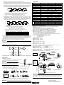
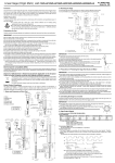
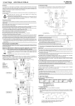
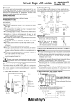
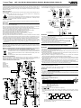
Linear Gage No. 99MBC102B1 Series No. 542 LGF-110L-B/125L-B/150L-B/0510L-B/0525L-B/0550L-B/525L-B/550L-B Foreword 2. Mounting the Gage To obtain the highest performance and the longest service life from your Linear Gage, carefully read this manual thoroughly prior to setup and operation. After reading this manual keep it near the Linear Gage for quick reference. The specifications of this gage and the description in this manual are subject to change without prior notification. To mount the gage on another instrument or a fixture, clamp the Φ8 stem or Φ15 stem. It is recommended to use a slotted holder or a split bushing for the mount structure. M4 x 0.7 thru 7.5 6 ・Example1 15 To ensure operator safety, use the instrument in conformance with the directions and specifications given in this User’s Manual. If a contact point with a sharp tip is used, exercise sufficient care in handling during replacement or use of it so as not to get hurt. If a contact point is released freely after it has been pressed in, the contact point may burst forth at a very high speed depending on the amount of spindle travel. Sufficiently exercise NOTE care so that your fingers or hand may not be pinched. Unit: mm 1 6 Safety Precautions 15 16 7.5 4.5 drill, 7.5 countersink, 4.4deep +0.020 +0.005 *2 Φ15 +0.024 +0.006 Cross section *1 Φ8 ・Example2 Carefully avoid the following attempts and conditions to protect the instrument from failure and malfunction. (2) Φ10 Φ17 (1) 12 *2 M4×0.7thru Notch position (90°with respect to tap) +0.020 +0.005 +0.024 *2 Φ15 +0.006 *1 Φ8 0 0 *1: For 10mm Stroke type *2 Φ17 -0.018 Cross section *1 Φ10 -0.015 (2)Split bushing 15 *2: For 25/50mm Stroke type 1 Do not apply sudden shocks including a drop or excessive force to the linear gage. Do not disassemble or modify the gage. Do not use and store the gage at sites where it is exposed to direct sunlight or at extremely hot or cold sites. To use the gage highly accurately, avoid sites where the temperature will change abruptly. Absolutely do not apply an electric engraver to the gage. The high voltage may damage electronic parts. Also, do not use the gage at sites where it is subject to large electric noises. Do not exert load on the spindle in the perpendicular direction and do not twist the spindle. Do not clamp the stem too tightly, since the spindle will not move smoothly. Do not apply excessive tension to the cable or do not bend it forcibly. To perform stable measurement, allow at least 10 minutes after turning on the power. Do not set up the origin point at either end of the stroke. If the gage is used in combination with other instruments, the maximum performance could not be obtained depending on environmental and operating conditions. Take those conditions into consideration prior to use. The functions and performance will not be guaranteed, if the gage is used in other conditions than those specified. Tale sufficient damage-preventive processing (safety measures), should this gage have been at fault. A contact point could hurt a workpiece depending on the workpiece material, measuring force, impact when the contact point comes in contact with the workpiece, etc. Check that there is no problem of hurts on a workpiece during measurement or accuracy variation depending on the measuring force, etc., in advance of use. 7.5 +0.005 +0.024 +0.006 IMPORTANT (1) 15 Precautions for Use 15 20 *1 +0.020 IMPORTANT Absolutely avoid pressing the stem directly with set screws. (The built-in bearing may be damaged.) Notice that excessively tightening the stem can cause trouble in the spindle operation. Never fix a linear gage at other than the stem. Mount the gages so that the spindle is directed perpendicular to the measured surface. If the gage is mounted at an angle to the measured surface, an error may be generated in measurement results. Exercise care so as not to exert a force on the gage through the cable. θ Error = L0 - L1 Electromagnetic Compatibility (EMC) This product complies with the EMC Directive. Note that in environments where electromagnetic interference exceeds EMC requirements defined in this directive, appropriate countermeasures are required to assure the product performance. Disposal of Old Electrical & Electronic Equipment (Applicable in the European Union and other European countries with separate collection systems) This symbol on the product or on its packaging indicates that this product shall not be treated as household waste. To reduce the environmental impact of WEEE (Waste Electrical and Electronic Equipment) and minimize the volume of WEEE entering landfills, please reuse and recycle. For further information, please contact your local dealer or distributors. Export Control Compliance The goods, technologies or software described herein may be subject to National or International, or Japanese Export Controls. To export directly or indirectly such matter without due approval from the appropriate authorities may therefore be a breach of export control regulations and the law. 1. Name and Dimension of Each Part (Hirose) (Thread height) (1) Stem (2) Rubber boot (3) Spindle (4) Contact point (5) Output cable (6) Output connector 3. Precautions in Protecting the Gage from Dust and Water IMPORTANT The output connector plug and preamplifier (counter side) is not protective structured. Install the gage at a place where it is not splashed directly with water or oil. If an extension cable is used, completely cover the preamplifier and connector area with a seal so as not to be exposed to environments. If the cable covering is broken, liquid will penetrate into the gage inside due to capillary phenomenon. This will cause damage to the gage. Immediately repair the cable. Be greatly careful not to damage the rubber boot due to chips, etc. If the rubber boot is damaged, dust-proof function will be deteriorated. Immediately replace or repair the rubber boot. The materials including rubber which are used for the rubber boot and other sealing parts are not universal against diversified coolants and chemicals. If those parts deteriorate unusually, consult the nearest Mitutoyo Service Center. If linear gages are used in adverse environments where they are subject to frequent splashes of water and oil, it is recommended to take preventive measures such as replacing them before being damaged. Each part of the gage is sealed up, and therefore must not be disassembled. If any part is disassembled, the rated performance will not be obtained. Do not absolutely disassemble the gage. 4. Connecting the Gage to a Counter Connect the output connector of the gage to the input connector on a linear gage counter. For detailed information, refer to the user’s manual of the linear gage counter. Cable length = 2m IMPORTANT If the gage cable is close to the power line for other instruments, the gage may malfunction. Connect the gage cable as apart from the power line as possible. If the gage is connected with other counter than Mitutoyo made, allow at least 0.2 second after the gage is turned on, then reset the counter. (Thrust stem mounting screw) 10.6 or more (stroke) LGF-0510L-B LGF-110L-B 5. Gage Output Signals (Hirose) (Thread height) (Hirose) (Thread height) Pin No. 1 2 Cable length = 2m Cable length = 2m 26 or more (stroke) Thrust stem mounting screw 1 1) Output connector: RM12BPE-6PH (Hirose) 2) Pin assignment LGF-0550L-B LGF-150L-B LGF-550L-B Signal name +5V *3 ΦA Pin No. 3 4 Signal name ΦB ΦA Pin No. 5 6 Signal name GND ΦB ΦB 51.5 or more (stroke) Tr (minimum) ⇒ 0.5μm, 1μm, 5μm (resolution) LGF-0525L-B LGF-125L-B LGF-525L-B 6 3 5 4 *3: Power supply to the gage head Power voltage; 5V (4.8N to 5.2V), Ripple voltage: 200mVp-p or less Current consumption: 120mA max. 3) Input/output signal level ΦA, ΦA, ΦB, ΦB, ΦZ (TTL line driver AM26LS31 or equivalent) 4) Output signal chart This series of gages are provided with the following three patterns for their output signals. Therefore, always design the reception circuitry so that it includes an error detecting process making use of these patterns: (A) Real-time pulse output (Phase-A wave advances when the spindle is retracted.) ΦA Thrust stem mounting screw 2 (1) Output condition: Spindle moving speed ≤ 250mm/s *4 (2) Minimum edge-to-edge interval of output pulses: Tr (See the following table.) (3) Output delay time *5: Max. 1μs (B) Burst pulse output (Phase-A wave advances when the spindle is retracted.) When the response speed reaches the speed limit of real-time pulse output, the linear gage will switch its signal output form to that consisting of burst pulses. At this time, these burst pulses will be such 2-phase square wave signals that are forcibly created from the internal clock so the minimum edge-to-edge interval in their output is smaller than the normal real-time pulse output. The burst pulses will not always be outputted so as to exactly reflect the actual motion and the delay in signals also becomes larger, but the counting values will be still valid as long as this output form continues. ΦA 7. Specifications Order NO. 542-161 542-162 542-163 Model No. LGF - 110L - B LGF – 125L - B LGF – 150L - B 1μm Resolution (1.5 + L/50) μm Accuracy (at 20 ℃) L = Measured length in mm 4μm Output signal pitch Minimum edge interval ΦB 500ns Order NO. 542-171 542-172 542-173 Model No. LGF – 0510 L - B LGF – 0525L - B LGF – 0550L - B Resolution Tb (minimum) ⇒ 0.5μm, 1μm, 5μm (resolution) 0.5μm (1.5 + L/50) μm Accuracy (at 20 ℃) (1) Output condition: 250 mm/s *4 < Spindle moving speed ≤ Gage response speed *6 (2) Minimum edge-to-edge interval of output pulses: Tb (See the following table.) (3) Output delay time *5: ●When feeding the spindle forward = Max. 5 μs ●When returning the spindle backward = Max. 10 μs (C) Error output The pulse generation circuit may sometimes overstep its response limit, if the output wave is subject to extreme disturbance due to vibration or impact in the gage unit, or if the spindle moves faster beyond the output limit of burst pulses. However, at this time, as the linear gage will automatically switch its output signal form from burst pulses to error pulses and also synchronize Phase A and Phase B of the 2-phase square wave signals, the user can make use of this facility for error detection. Output signal pitch 2μm Minimum edge interval 250ns Order NO. - 542-612 542-613 Model No. - LGF – 0525L - B LGF – 0550L - B Resolution - Accuracy (at 20℃) - Output signal pitch - Minimum edge interval Meas. force ΦA 5μm (7.5 + L/50)μm L = Measured length in mm 20μm - Measuring range ΦB L = Measured length in mm 1000ns 10mm 25mm 50mm Contact point downwards 1.2 N or less 4.6 N or less 5.7 N or less Contact point horizontal 1.1 N or less 4.3 N or less 5.3 N or less Contact point upwards 1.0 N or less 4.0 N or less 4.9 N or less Φ8 Stem Diameter Φ15 Te (minimum) (1) Output condition: The gage will be identified as error under the following conditions and produce its output in one of the above described special patterns. ● Gage response speed *6 < Spindle moving speed ● At a disturbance such as noise interference, vibration, etc. (2) Minimum edge-to-edge interval of output pulses: Te (See the following table.) Minimum edge-to-edge interval / pulse width under each condition Resolution Tr (for real-time pulse) Tb (for burst pulse) 5μm 1μs 1μs 1μm 1μs 0.5μs 0.5μm 1μs 0.25μs Te (for error pulse) 0.25μs 0.25μs 0.25μs *4: The actual limit of real-time pulse output will be depreciated to this value. This is because actual detection signals unavoidably contain acceleration components in association with the spindle motion as well as error components from a minute noise included in the signal itself. As a result, some burst pulses at a speed below the ideal conditions (i.e. ideal signal form at constant speed) may be generated. *5: Output delay time: Time until the counting pulse catches up the spindle position *6: Gage respond speed: Refer to the section of specifications of the Users Manual. IMPORTANT Since any output during error can not be used as the attribute data, it is necessary to detect the error condition at the reception circuitry side. It is recommended to design user circuitry based on an IC chip that is capable of counting at 5 Mcps (equivalent to a square wave of 1.25 MHz) or greater. 5) Input connector and recommended input circuit connector: RM12BRD-6S (HIROSE ELECTRIC) LGF output circuit Recommended input circuit ΦA, ΦB 33pF ΦA, ΦB Specifications common to all series ●Quantizing error: ±1 count ●Positional sensor: Photoelectric transmission linear encoder ●Response speed: 1.5m/s *7 ●Output method: 90°phase differential square wave (compatible with RS-422A) Refer to the above table for Output Signal pitch and Minimum edge interval ●Contact point: Φ3 carbide ball(Thread: M2.5x0.45) ●Bearing type: Stroke ball bearing ●Protection level: IP66 ●Output cable length: 2m(directly wired from the gage) ●Operating temperature (humidity) :0 to 40 ℃ (20 to 80%RH, with no condensation) ●Storage temperature (humidity) : -10 to 60 ℃ (20 to 80%RH, with no condensation) ●Accessory: No. 538610 Key spanner for contact point replacement (10mm type) No. 210187 Key spanner for contact point replacement (25/50mm type) *7: In the case of 50mm stroke type, an over speed error may occur depending on the spindle retraction amount, if the contact point is released freely after it is retracted. ●CE marking: EMC Directive:EN61326-1 Immunity test requirements: Clause 6.2 Table2 Emission limit: Class B 8. Optional Accessories ●Extension cable(5m) : No. 902434 ●Extension cable(10m) : No. 902433 ●Extension cable(20m) : No. 902432 ●Rubber boot (for 10mm type) : No. 238772 ●Rubber boot (for 25mm type) : No. 962504 ●Rubber boot (for 50mm type) : No. 962505 If the thrust stem and tightening nut are used, the gage mount fixture needs only Φ9.5 or Φ18 hole to be drilled, and also the gage can be mounted firmly and easily. (see below.) Thrust stem set (for 10mm type) ●Thrust stem (for 10mm type) :No. 02ADB682 No.02ADB680 ●Tightening nut (for 10mm type) :No. 02ADB682 ●Dedicated spanner (for 10mm type) : No. 02ADB683 51Ω 26LS32 or equivalent +5V +5V ●Thrust stem (for 25/50mm type) :No. 02ADN371 ●Tightening nut (for 25/50mm type) :No. 02ADB692 ●Dedicated spanner (for 25/50mm type) :No. 02ADB693 =Example of use= Thrust stem set (for 25/50mm type) No.02ADN370 Dedicated spanner Thrust stem ( Optional accessories ) ( Optional accessories ) LGF-0510L-B LGF-110L-B GND GND 6) Cable extendible length: The cable can be extended up to 20m using the extension cable (optional). Thrust stem / Mounting nut Mounting nut 6. Maintenance ( Optional accessories ) 1) Replacing the contact point Fit the supplied key spanner in the keyway of the spindle, then detach or attach the contact point by pinching it with a wrench, etc. LGF-0525L-B LGF-125L-B LGF-525L-B LGF-0550L-B LGF-150L-B LGF-550L-B IMPORTANT Key Way LGF-0510L-B LGF-110L-B LGF-0525L-B LGF-125L-B LGF-0550L-B LGF-150L-B Stem Key Way Spindle Rubber boot Key Way ( Optional accessories ) Rubber boot Mounting nut Thrust stem / Mounting nut ( Optional accessories ) Dimension between hexagonal opposing sides Fixture width L: within 10 to 13mm Contact point IMPORTANT (A) (A) Dedicated spanner Key spanner (for replacing contact points) (1) Remove the old rubber boot, then eliminate the dust and dirt in the grooves (part A) of the stem and spindle. (A) (A) Stem Spindle Thrust stem ( Optional accessories ) For 25mm stroke = (84.1) 2) Replacing the rubber boot Preventive replacement before being damaged is recommendable. (The rubber boot is available as an optional accessory.) Fixture width L: within 6 to 10.5mm For 50mm stroke = (124.9) If torque is applied to the sensor inside through the spindle, damage or malfunction in the sensor may result. Be sure to fix the spindle using the key spanner. Dimension between hexagonal opposing sides Before mounting the trust stem, be sure to secure the stem using the dedicated spanner (No.02ADB683/ No.02ADB693). Excessive force applied between the gage body and stem may cause damage to the gage. M9 x 0.5/M14 x 0.5 screw are sued only for mounting the trust stem. Do not use them for other purposes. Contact point (2) Insert a rubber boot between the stem and contact point, directing the greater inside diameter end to the stem. (3) Apply a small amount of silicone adhesive to the grooves (part A), and seal both ends of the rubber boot. IMPORTANT Mitutoyo Corporation If the adhesive is applied to the spindle, the spindle will not slide properly. Great care must be exercised. 20-1, Sakado 1-Chome, Takatsu-ku, Kawasaki-shi, Kanagawa 213-8533, Japan