1
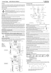
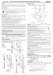
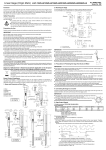
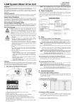
No.99MBC081B② SeriesNo.542 Linear Gage LGK series Foreword 2. Mounting the Gage To obtain the highest performance and the longest service life from your Linear Gage, carefully read this manual thoroughly prior to setup and operation. After reading this manual keep it near the Linear Gage for quick reference. The specifications of this gage and the description in this manual are subject to change without prior notification. (1)To mount the gage on another instrument or a fixture, clamp the φ8 stem. (2)It is recommended to use a slotted holder or a split bushing for the mount structure.(Recommended tightening torque in Example 1:4.0 to 5.0kgf・cm) Safety Precautions ・Example 1. 16 M4×0.7 thru 15 1 unit:mm 6 7.5 6 7.5 15 To ensure operator safety, use the instrument in conformance with the directions and specifications given in this User’s Manual. Precautions for Use Carefully avoid the following attempts to protect the instrument from failure and malfunction. Caution Please be careful enough when handling the knife edge or blade type contact point, since there is a possibility of injury at exchange and use. Electromagnetic Compatibility (EMC) This product complies with the EMC Directive. Note that in environments where electromagnetic interference exceeds EMC requirements defined in this directive, appropriate countermeasures are required to assure the product performance. 1. Name and Dimension of Each Part 73.1 125.5 0 φ 8 -0.009 ① 30 10.6 or more(stroke) ③ 31.9 ② 14 6.5 82.7 Thrust stem mounting screw M9.5×0.5 RM12BPE-6PH ⑥ (Hirose) unit:mm ⑤ Ring of discriminating a model ② φ 10 7.5 10 +0.020 +0.005 φ 10 0 -0.015 φ8 +0.020 +0.005 M4×0.7 thru ① 1 cross section Notch position (90°with respect to tap) IMPORTANT θ Absolutely avoid pressing the stem directly with set screws. (The built-in bearing may be damaged.) Mount the gage so that the spindle is directed perpendicular to the measured surface. If the gage is mounted at an angle to the measured surface, an error may be generated in measurement results. Error=L0-L1 3. Precautions in Protecting the Gage from Dust and Water IMPORTANT The output connector plug (counter side) is not protective structured. Install the gage at a place where it is not splashed directly with water or oil. If the cable covering is broken, liquid will penetrate into the gage inside due to capillary phenomenon. This will cause damage to the gage. Immediately repair the cable. Be greatly careful not to damage the rubber boot due to chips, etc. If the rubber boot is damaged, dust-proof and water-proof function will be deteriorated. Immediately replace or repair the rubber boot. The materials including rubber which are used for the rubber boot and other sealing parts are not universal against diversified coolants and chemicals. If those parts deteriorate unusually, consult the nearest Mitutoyo Service Center. Each part of the gage is sealed up, and therefore must not be disassembled. If any part is disassembled, the rated performance will not be obtained. Do not absolutely disassemble the gage. 4. Specifications of Gage Output Signals φ 12 Cable length 2m ②Split bushing ① 15 Do not apply sudden shocks including a drop or excessive force to the linear gage. Do not disassemble or modify the gage. Do not use and store the gage at sites where it is exposed to direct sunlight or at extremely hot or cold sites. To use the gage highly accurately, avoid sites where the temperature will change abruptly. Absolutely do not apply an electric engraver to the gage. The high voltage may damage electronic parts. Also, do not use the gage at sites where it is subject to large electronic noises. Do not exert load on the spindle in the perpendicular direction and do not twist the spindle. Do not clamp the stem too tightly, since the spindle will not move smoothly. Do not apply excessive tension to the cable or do not bend it forcibly. To perform stable measurement, allow at least 10 minutes after turning on the power. Do not set up the origin point at either end of the stroke. If the gage is used in combination with other instruments, the maximum performance could not be obtained depending on environmental and operating conditions. Take those conditions into consideration prior to use. The functions and performance will not be guaranteed, if the gage is used in other conditions than those specified. Take sufficient damage-preventive processing (safety measures), should this gage have been at fault. 15 20 ・Example 2. 4.5 drill, 7.5 countersink, 4.4 deep +0.020 +0.005 15 IMPORTANT cross section φ8 ①Stem ②Rubber boot ③Spindle ④Contact point ⑤Signal cable ⑥Output connector 1) Output connector:RM12BPE-6PH (Hirose) 2) Pin assignment Pin No. Signal name 1 ※ 1 +5V ※ :Power supply to the gage head 2 6 2 φA Power voltage:5V(4.8V to 5.2V) 3 φB Ripple voltage:200mVp-p or less 4 φA Current consumption:120mA max. 3 5 5 GND 4 6 φB 3) Output signal level φA、φA、φB、φB(TTL line driver AM26LS31 or equivalent) 4) Input connector and recommended input circuit Suitable connector:RM12BRD-6S (Hirose) LGK output circuit Recommended input circuit φ A,φ B 33pF φ A,φ B ④ 51Ω +5V +5V GND GND 26LS32 or equivalent 5) Output signal chart This Linear gage outputs two patterns of waveform signal shown below. When designing an input circuit, error detection function must be prepared. (1) Real-time pulse output (When the spindle is pushed in,φA precedes φB) phase A Phase B Tr(MIN) → 1μ m/0.5μ m/0.1μ m(Resolution) ①Output condition : Spindle movement speed ≦ Response speed※1 ②Output signal’s minimum edge interval : Tr※2 ③Output delay※3: Maximum 2.5μs (2) Error output phase A Phase B T e(MIN) ①Output condition : In the conditions below, the gage turns to the error status and outputs the special pattern shown in the above. Response speed※1 < Spindle movement speed When suffering electric noise or physical shock. ②Output minimum pulse width : Te※2 ※1 )Response speed : See specifications. )Minimum edge interval, pulse width : See specifications. ※3 )Output delay : The time required for the output to catch up with the spindle position. 6) Cable extendible length The cable can be extended up to 20m using the extension cable (optional). ※2 IMPORTANT Since error output can not be used as the counting data, the error condition must be detected in the input circuit. It is recommended to use a counter IC which can count 5Mcps (1.25MHz in square wave signal) or higher. If the gage cable is close to the power line for other instruments, the gage may malfunction. Connect the gage cable as apart from the power line as possible. If the gage is connected with other counter than Mitutoyo made, allow at least 0.2 second after the gage is turned on, then reset the counter. 6. Specifications Order No. Model Measuring range Resolution Color of ring of discriminating a model Accuracy(at 20℃) Quantizing error Measuring force Contact point downward Contact point horizontal Contact point upward Positional sensor Response speed Output method Signal type 0.1μm Green Blue Gold (1.5+L/50)μm ±1count ※1 (0.8+L/50)μm 0.8N or less 0.75N or less 0.7N or less Photoelectric transmission linear encoder 1500mm/s 1500mm/s 400mm/s ※1:L=Measured length in mm 7. Optional Accessories (must be purchased separately) P ar t n am e Extension cable(5m) Extension cable(10m) Extension cable(20m) Rubber boot Thrust stem ★ Tightening nut ★ Dedicated spanner ★ Order No. No.902434 No.902433 No.902432 No.238772 No.02ADB681 No.02ADB682 No.02ADB683 Thrust stem No.02ADB681 (A) If the thrust stem and tightening nut are used, the gage mount fixture needs only a φ9.5 hole to be drilled, and also the gage can be mounted firmly and easily. 14.5 0 4 L To use the thrust stem, the above three kinds of Optional accessories (★-marked) are required. φ 9.5 -0.015 (30.4) Key spanner (for replacing contact points) (Standard accessory: 538610) 5 NOTE KeyWay Mounting nut No.02ADB682 Fixture width L:6 to 10.5mm Thrust stem and Mounting nut dimension 13.25 12 (A) 0.5μm Example use of thrust stem 2) Replacing the rubber boot Preventive replacement before being damaged is recommendable. (The rubber boot is available as an optional accessory.) (1) Remove the old rubber boot, then eliminate the dust and dirt in the grooves (part A) or the stem and spindle. Stem 542-158 LGK-0110 Immunity test requirements :Clause 6.2 Table2 Emission limit :Class B 1) Replacing the contact point Fit the supplied key spanner in the keyway of the spindle, then detach or attach the contact point by pinching it with, etc. If torque is applied to the sensor inside through the spindle, damage or malfunction in the sensor may result. Be sure to fix the spindle using the key spanner. 542-157 LGK-0510 90°phase differential square wave (Compatible with RS422A) Differential square wave pitch 4μm 2μm 0.4μm Minimum edge interval, Tr : 0.4μs Tr : 0.2μs Tr : 0.2μs Minimum pulse width Te : 0.4μs Te : 0.2μs Te : 0.2μs Contact point φ3 carbide ball (Thread: M2.5 x 0.45) Stem diameter φ8 Bearing type Stroke ball bearing Protection level IP66 Output cable length 2m (directly wired from the gage) Operating temperature(Humidity) 0 to 40℃ (20 to 80%RH, with no condensation) Storage temperature(Humidity) -10 to 60℃ (20 to 80%RH, with no condensation) Key spanner for contact point replacement Standard accessory (No.538610) EMC Directive:EN61326-1 CE marking 5. Maintenance IMPORTANT 542-156 LGK-110 10mm 1μm IMPORTANT Spindle KeyWay Rubber boot contact point (2) Insert a rubber boot between the stem and contact point, directing the greater inside diameter end to the stem. (3) Apply a small amount of silicone adhesive to the grooves (part A), and seal both ends of the rubber boot. Before mounting the thrust stem, be sure to secure the stem using the dedicated spanner (No.02ADB683). Excessive force applied between the gage body and stem may cause damage to the gage. NOTE The dedicated spanner (No.02ADB683) and M9.5 x 0.5 screw are used only for mounting the thrust stem. Do not use them for other purposes. IMPORTANT If the adhesive is applied to the spindle slider, the spindle will not slide properly. Great care must be exercised. Mitutoyo Corporation 20-1, Sakado 1-Chome, Takatsu-ku, Kawasaki-shi, Kanagawa 213-8533, Japan