1
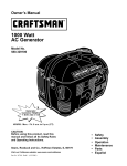
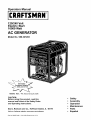
Operators Manual
CRRFTSHRN°
120/240 Volt
Electric Start
10000 Watt
AC GENERATOR
Model No 580.327203
C usGemneraHt°lpl
ine_
HOURS:
Mon.- Fri. 8 a.m. to 5 p.m. (CT)
CAUTION:
Before using this product, read this
manual and follow all its Safety Rules
and Operating Instructions
Sears, Roebuck
and Co,
Hoffman
Estates,
Visit our Craftsman website: www.sears.com/craftsman
Part No. B4659 Draft 1 (10/1/1999)
Printed in the U.S.A.
IL 60179
•
•
•
•
•
Safety
Assembly
Operation
Maintenance
Parts
•
Espahol
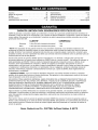
Warranty .................................
Safety Rules ..............................
Assembly .................................
Operation ..............................
Product Specifications ......................
Maintenance ...........................
Storage .................................
LIMITED
2
3
4
5-12
13
13-16
17
WARRANTY
Troubleshooting ...........................
Wiring Diagram/Schematic ................
Replacement Parts ......................
Emissions Warranty .....................
EspaSol ..............................
How to Order Parts ..................
FOR DELUXE
PORTABLE
18
20-21
22-33
34-34
36-55
Back Page
GENERATORS
SEARS warrants to the original purchaser that the alternator and engine for its portable generator will be free
from defects in materials or workmanship for the items and period set forth below from the date of original
purchase. This warranty is not transferable and applies only to portable generators driven by the Sears
warranted engine.
CONSUMER*
COMMERCIAL*
Alternator
2 years (2nd year parts only)
1 year
Engine
2 years (2nd year parts only)
1 year
* NOTE: For the purpose of this warranty "Consumer Use" means personal residential household and
emergency use by original purchaser, not to be used as a primary source of power. "Commercial Use" means all
other uses, including rental, construction, commercial, and income producing purposes. Once a generator has
experienced commercial use, it shall thereafter be considered a commercial use generator for the purpose of
this warranty.
During said warranty period, SEARS will, at its option, repair or replace any part which, upon examination by
SEARS, is found to be defective under normal use and service**. Starting batteries are not warranted by
SEARS. All transportation costs under warranty, including return to the factory if necessary, are to be borne by
the purchaser and prepaid by him. This warranty does not cover normal maintenance and service and does not
apply to a generator set, alternator or engine, or parts which have been subjected to improper or unauthorized
installation or alteration, misuse, negligence, accident, overloading, overspeeding, improper maintenance, repair
or storage so as, in SEARS's judgment, to adversely affect its performance and reliability.
** NORMAL WEAR: As with all mechanical devices, engines need periodic parts service and replacement to
perform well. This warranty will not cover repair when normal use has exhausted the life of a part or engine.
THERE IS NO OTHER EXPRESS WARRANTY. SEARS HEREBY DISCLAIMS ANY AND ALL
IMPLIED WARRANTIES, INCLUDING BUT NOT LIMITED TO THOSE OF MERCHANTABILITY AND
FITNESS FOR A PARTICULAR PURPOSE TO THE EXTENT PERMITTED BY LAW. THE DURATION
OF ANY IMPLIED WARRANTIES WHICH CANNOT BE DISCLAIMED IS LIMITED TO THE TIME
PERIOD AS SPECIFIED IN THE EXPRESS WARRANTY. LIABILITY FOR CONSEQUENTIAL,
INCIDENTAL, OR SPECIAL DAMAGES UNDER ANY AND ALL WARRANTIES IS EXCLUDED.
Some states do not allow limitations on how long an implied warranty lasts, or the exclusion or limitation of
incidental or consequential damages, so the above limitations or exclusions may not apply to you. This warranty
gives you specific legal rights and you may also have other rights, which vary from state to state.
For service, see your nearest SEARS authorized warranty service facility. Warranty service can be performed
only by a SEARS authorized service facility. This warranty will not apply to service at any other facility. At the
time of requesting warranty service, evidence of original purchase date must be presented.
Sears, Roebuck
and Co., D/817WA,
Hoffman
Estates,
IL 60179
LOOK FOR THIS SYMBOL TO POINT OUT
IMPORTANT SAFETY PRECAUTIONS. IT
MEANS "ATTENTION!!! BECOME ALERT!!!
YOUR SAFETY IS INVOLVED."
CAUTION! Before using this product, read
this manual and follow all Safety Rules and
Operating Instructions.
DANGER! This generator is designed for
outdoor use only. Do not use this generator
inside any building or enclosure including the
generator compartment of a recreational
vehicle (RV). Fire or an explosion may result.
No user performed modifications, including
venting of exhaust and/or cooling ventilation,
will eliminate the danger. Also, allow at least
two feet of clearance on all sides of the
generator even while operating the unit
outdoors.
CAUTION! Always disconnect spark plug wire
and place the wire where it cannot contact the
spark plug. To prevent accidental starting when
setting up, transporting, adjusting or making
repairs to your generator.
•
•
The generator produces dangerously high voltage
that can cause extremely hazardous electrical
shock. Avoid contact with bare wires, terminals,
etc. Never permit an unqualified person to operate
or service the generator.
Never handle any kind of electrical cord or device
while standing in water, while barefoot or while
hands or feet are wet. Dangerous electrical shock
will result.
•
The National Electric Code requires the frame and
external electrically conductive parts of generator
be properly connected to an approved earth
ground. Local electrical codes may also require
proper grounding of the generator. Consult with a
local electrician for grounding requirements in your
area.
•
Use a ground fault circuit interrupter in any damp
or highly conductive area (such as metal decking
or steel work).
•
Do not use worn, bare, frayed or otherwise
damaged electrical cord sets with the generator.
Using any defective cord set may result in
electrical shock or damage to property.
•
Operate generator only on level surfaces and
where it will not be exposed to excessive moisture,
dirt, dust or corrosive vapors.
•
Gasoline is highly FLAMMABLE and its vapors are
EXPLOSIVE. Do not permit smoking, open flames,
sparks or heat in the vicinity while handling
gasoline. Avoid spilling gasoline on a hot engine.
Comply with all laws regulating storage and
handling of gasoline.
•
Never add fuel while unit is running.
•
Do not overfill the fuel tank. Always allow room for
fuel expansion. If tank is overfilled, fuel can
overflow onto a hot engine and cause FIRE or an
EXPLOSION.
•
Never store generator with fuel in tank where
gasoline vapors might reach an open flame or
spark or pilot light (as on a furnace, water heater
or clothes dryer). FIRE or EXPLOSION may result.
•
Generator exhaust gases contain DEADLY carbon
monoxide gas. This dangerous gas, if breathed in
sufficient concentrations, can cause
unconsciousness or even death. Operate this
equipment only in the open air where adequate
ventilation is available.
•
Allow at least 2 feet of clearance on all sides of
generator, even while operating unit outdoors, or
you could damage the unit. Never operate the unit
inside a room or enclosure where the free flow of
cooling air into and out of the unit might be
obstructed.
•
Never start or stop the unit with electrical loads
connected to receptacles AND with the connected
devices turned ON. Start the engine and let it
stabilize before connecting electrical loads.
Disconnect all electrical loads before shutting
down the generator.
•
Do not insert any object through cooling slots of
the unit.
•
Never operate generator (a) in rain; (b) in any
enclosed compartment; (c) if connected electrical
devices overheat; (d) if electrical output is lost; (e)
if engine or generator sparks; (f) if flames or
smoke are observed while unit is running; (g) if
unit vibrates excessively.
NOTE: Your generator is equipped with a spark
arrestor muffler, the spark arrestor must be
maintained in effective working order by the owner/
operator. In the State of California a spark arrestor is
required by law (Section 4442 of the California Public
Resources Code). Other states may have similar
laws. Federal laws apply on federal lands.
Yourgeneratorrequiressomeassemblyandis ready
foruseafterit hasbeenproperlyservicedwiththe
recommended
oilandfuel.
If you haveanyproblemswith the assemblyof
your generator,pleasecallthe generatorhelpline
at 1-800-222-3136.
Important:Anyattemptto runtheenginebeforeit has
beenservicedwiththerecommended
oilwillresultin
anenginefailure.
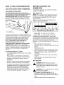
TO REMOVE THE GENERATOR
FROM CARTON
•
Set the palleted carton on a rigid flat surface.
•
Carefully cut bands around the shipping carton.
•
Lift carton off the generator.
•
Remove all packing material, carton fillers, etc.
•
Remove the generator from the shipping pallet.
CARTON
Connect the red battery cable to the engine starter
switch.
CONTENTS
Check all contents. If any parts are missing or
damaged, call the generator helpline at
1-800-222-3136. Contents include:
•
10,000 Watt generator
•
Battery charge cables
•
•
3 Locking plugs
Owner's manual
•
Engine oil
•
Battery hold down components
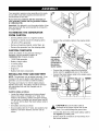
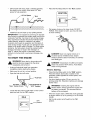
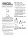
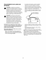
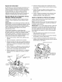
INSTALLING
TRAY AND BATTERY
Connect :h_
red battery
cable to this
connection on
the electric
starter switch.
•
Connect the red battery cable from the electric
starter switch to positive (+) post on the battery.
•
Connect the black battery cable to the engine using
the M8 x 1.25 inch bolt.
NOTE: The generator can be started manually. If you
choose not to use the electric start feature of this
generator, you do not need to install the battery.
Purchase and install a 12 Volt DC battery (Sears
DieHard 28-27135). The battery should be serviced
with electrolyte fluid and fully charged prior to
installation.
Install the battery as follows:
•
Locate the battery fasteners and wires shipped
loose in the carton. Included are 7" bolts, lock
washers, flat washers, battery hold down bracket,
and hex nuts. In addition you should have one M8
x 1.25 inch bolt to attach the black battery cable to
the engine.
•
Set battery onto tray as shown.
•
Secure battery with the 7" bolts, lock washers, flat
washers, hold down bracket, and hex nuts as
shown.
Connect
black battery
cable here
using M8 x
1.25 bolt.
_
connected
CAUTION! to Be
thesure
engine
the mount
black cable
and not
is the
frame. You could damage the ground wire.
•
Connect the other end of the black battery cable to
the negative (-) battery post.
•
Double check all connections to insure they are in
the correct locations.
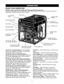
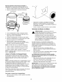
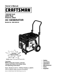
KNOW YOUR GENERATOR
Read the owner's manual and safety rules before operating your generator.
Compare the illustrations with your generator to familiarize yourself with the locations of various controls and
adjustments. Save this manual for future reference
Fuel Shut-off
Valve
Fuel Tank
Electric Start
J
Button
Circuit Breakers (AC)
Air Cleaner
(on top of engine)
Hour Meter
Choke Lever
Run/Stop Switch
Idle Control Switch
Spark Arrestor
Muffler
12 Volt DC, 10 Amp
Receptacle
120/240 Volt AC,
50 Amp Receptacle
120 Volt AC, 20 Amp
GFCI Duplex Receptacle
120 Volt AC, 20 Amp
Locking Receptacle
120/240 Volt AC, 30 Amp
Locking Receptacle
120 Volt AC, 30 Amp
Locking Receptacle
Grounding Lug
12 Volt DC, 10 Amp Receptacle --This receptacle
allows you to recharge a 12 Volt DC storage battery
with provided battery charge cable.
Air Cleaner -- Filters intake air as it is drawn into the
engine.
120 Volt AC, 20 Amp Locking Receptacle -Supplies electrical power for the operation of 120 Volt
AC, 20 Amp, single phase, 60 Hz electrical lighting,
appliance, tool and motor loads.
Circuit Breakers (AC) -- Each receptacle is provided
with a circuit breaker to protect the generator against
electrical overload. Breakers are "push to reset" type.
120 Volt AC, 20 Amp, GFCI, Duplex Receptacles -Each socket supplies electrical power for the operation
of 120 Volt AC, 20 Amp, single phase, 60 Hz electrical
lighting, appliance, tool and motor loads. Circuits are
protected with a ground fault interrupt device.
120 Volt AC, 30 Amp Locking Receptacle -Supplies electrical power for the operation of 120 Volt
AC, 30 Amp, single phase, 60 Hz electrical lighting,
appliance, tool and motor loads.
120/240 Volt AC, 30 Amp Locking Receptacle -Supplies electrical power for the operation of
120 and/or 240 Volt AC, 30 Amp, single phase, 60 Hz
electrical lighting, appliance, tool and motor loads.
120/240 Volt AC, 50 Amp -- Supplies electrical
power for the operation of 120/240 Volt AC, 50 Amp,
single phase, 60 Hz, welder or motor loads.
Choke Lever--
Electric
Used when starting a cold engine.
Start Button -- Pressed to start the engine.
Fuel Shut Off Valve -- Used to stop the supply of
gasoline to the carburetor.
Fuel Tank -- Tank holds 10 U.S. gallons of unleaded
gasoline.
Grounding
ground.
Lug -- Used to connect unit to earth
Hour Meter -- Measures engine running time.
Idle Control Switch -- The idle control runs the
engine at normal (high) speeds when there is a load
present and runs the engine at idle (low) speeds when
a load is not present.
Run/Stop Switch -- Must be in "Run" position to start
engine. Set to "Stop" to stop a running engine.
Spark Arrestor Muffler -- Muffler lowers engine
noise and is equipped with a spark arrestor screen.
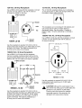
CORD SETS AND CONNECTOR
PLUGS
Testing
120 Volt, 20 Amp, GFCI, Duplex
Receptacle
1. Push the black "TEST" button. The red "RESET"
button should pop out, which should disconnect
power from the outlet. Use a test lamp and test
each outlet.
This is a 120 Volt ground fault circuit interrupter
(GFCI) outlet, consisting of a pair of receptacles
protected against overload by a 20 Amp push-to-reset
circuit breaker. Use each receptacle to power 120 Volt
AC, single phase, 60 Hz electrical loads requiring up
to a combined 2400 watts (2.4 kW) or 20 Amps of
current.
I
I RESET I
I TESTI
4
u
the GFCI Outlet
Test your GFCI outlet every month. Follow these
instructions:
,_
DANGER:
If the
"RESET"
does
out
or the test
lamp
remainsbutton
lit when
the not pop
"RESET" button is popped out, do not use any
outlets on the circuit. Call a qualified electrician.
2. If the GFCI tests good, restore power by pressing
the "RESET" button firmly until it is fully in place
and locks in that position. If the GFCI outlet does
not reset properly, do not use the outlet -- call a
qualified electrician.
3. If the GFCI trips by itself at any time, reset and test
the outlet. If the reset button does pop out when
the test button is pressed, do not use the outlet.
Call a qualified electrician.
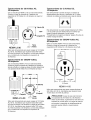
120 Volt AC, 20 Amp Receptacle
Use a NEMA L5-20 plug with this receptacle. Connect
a 3-wire cord set rated for 125 Volt loads at 20 Amps
(or greater) to the plug.
3-Wire Cord Set
Use only high quality, well-insulated, 3-wire grounded
cord sets rated 125 Volts at 20 Amps (or greater).
Keep extension cords as short as possible, preferably
less than 15 feet long, to prevent voltage drop and
possible overheating of wires.
Ground
Neutral
120V
Fault Protection
The generator is equipped with a Ground Fault Circuit
Interrupter (GFCI). This device meets all requirements
of applicable federal, state and local codes.
Hot
The GFCI protects against electrical shock that may
be caused if your body becomes a path which
electricity travels to reach ground. This could happen if
you touch a "Live" appliance, or cord or are touching
plumbing or other materials that go to ground.
When protected by a GFCI, a person will still feel a
shock, but the GFCI should cut it off quickly enough
so that a person in normal health should not suffer any
serious electrical injury.
,_
DANGER:
The GFCIsituations:
will not protect
you
against the following
(1) Line-to-line
shocks; (2) Current overloads or line-to-line
short circuits. The fuse or circuit breaker at the
distribution panel must provide such protection.
NEMA L5-20
/_
Ground
(Green)
Use this receptacle to operate 120 Volt AC, 60 Hz,
single phase loads requiring up to 2400 watts (2.4 kW)
of power at 20 Amps. The outlet is protected by a
20 Amp push-to-reset circuit breaker.
120 Volt, 30 Amp Receptacle
12 Volt DC, 10 Amp Receptacle
Use a NEMA L5-30 plug with this receptacle. Connect
a 3-wire cord set rated for 125 Volt AC loads at
30 Amps (or greater) to the plug.
3-Wire Cord Set
The 12 Volt DC receptacle allows you to recharge a
12 Volt automotive or utility style storage battery with
the battery charge cables provided.
Neutral
120V
Hot
This receptacle can not recharge 6 Volt batteries and
can not be used to crank an engine having a
discharged battery. See the section "Charging a
Battery" (page 11) before attempting to recharge a
battery.
120/240 Volt AC, 50 Amp Receptacle
NEMA L5-30
/__
Use a NEMA 14-50 plug with this receptacle. Connect
a 4-wire cord set rated for 250 Volt AC loads at
50 Amps to the plug.
Ground
(Green)
240 Volts AC
Use this receptacle to operate 120 Volt AC, 60 Hz,
single phase loads requiring up to 3600 watts (3.6 kW)
of power at 30 Amps. The outlet is protected by a
30 Amp push-to-reset circuit breaker.
Frame Ground
120/240 Volt, 30 Amp Receptacle
Use a NEMA L14-30 plug with this receptacle.
Connect a suitable 4-wire grounded cord set to the
plug and to the desired load. The cord set should be
rated for 250 Volt AC loads at 30 Amps (or greater).
4-Wire Cord Set
Y (Hot)
X (Hot)
120 Volts
AC -----_
AC
W (Neutral)
W (Neutral)
NEMA 14-50
X (Hot)
Y (Hot)
N EMA L14-30
Ground
(Green)
Use this receptacle to operate 120 Volt AC, 60 Hz,
single phase loads requiring up to 3600 watts (3.6 kW)
of power at 30 Amps or 240 Volt AC, 60 Hz, single
phase loads requiring up to 7200 watts (7.2 kW) of
power at 30 Amps. The outlet is protected by a
30 Amp push-to-reset circuit breaker.
Use this receptacle to operate 240 Volt AC, 60 Hz,
single phase loads requiring up to 10,000 watts
(10.0 kW) of power.
,_
CAUTION!
Although
stateswatts),
it has the
a
240
Volt 50 Amp
ratingthis
(upoutlet
to 12,500
generator is only rated for 10,000 watts.
Powering loads that exceed the wattage/
amperage capacity of the generator can
damage it and cause serious injuries.
HOW TO USE YOUR GENERATOR
If you have any problems operating your generator,
please call the generator helpline at 1-800-222-3136.
Grounding
The Generator
The National Electrical Code requires that the
frame and external electrically conductive parts of
this generator be properly connected to an
approved earth ground. Local electrical codes may
also require proper grounding of the unit. For that
purpose, a grounding lug is provided on the base of
the cradle.
BEFORE STARTING
GENERATOR
To operate the generator you will need to first add
engine oil and gasoline:
Add Engine
Oil
NOTE: When adding oil to the engine crankcase in
the future, use only high quality detergent oil rated
with API service classification SF or SG. Use no
special additives.
Select the oil's viscosity grade according to your
expected operating temperature:
°F -20
/1
THE
0
°c. 0
20 32 40
-i0
6
60
80
100
1'0
TemperatureRangeof ExpectedUse
Grounding Lug
Generally, connecting a No. 12 AWG (American Wire
Gauge) stranded copper wire to the grounding lug and
to an earth-driven copper or brass grounding rod
(electrode) provides adequate protection against
electrical shock. However, local codes may vary
widely. Consult with a local electrician for
grounding requirements in your area.
Proper grounding of generator will help prevent
electrical shock in the event of a ground fault
condition in the generator or in connected electrical
devices. Proper grounding also helps dissipate static
electricity, which often builds up in ungrounded
devices.
Connecting
Electrical
Let engine stabilize and warm up for a few minutes
after starting.
•
Plug in and turn on the desired 120 Volt AC or
240 Volt AC, single phase, 60 Hz electrical loads.
DO NOT connect 240 Volt loads to 120 Volt
receptacles.
•
Above 40°F, use SAE 10W-30 or SAE 30.
•
Below 40°F, use synthetic 5W-20 or 5W-30
Although multi-viscosity oils (5W30, 10W30, etc.)
improve starting in cold weather, these multi-viscosity
oils will result in increased oil consumption when used
above 32°F. Check your engine oil level more
frequently to avoid possible damage from running low
on oil.
•
Place generator on a level surface.
•
Clean area around oil fill and remove oil fill cap and
dipstick.
•
Wipe dipstick clean.
•
Slowly fill engine with oil through the oil fill opening
until it reaches the full mark on the dipstick. Stop
filling occasionally to check oil level. DO NOT
OVERFILL.
•
Install dipstick. Install oil fill cap and hand tighten
securely.
•
Check engine oil level before starting unit each
time thereafter.
Loads
•
•
•
DO NOT connect 3-phase loads to the generator.
•
DO NOT connect 50 Hz loads to the generator.
•
Add up the rated watts (or amps) of all loads to be
connected at one time. This total should not be
greater than (a) the rated wattage/amperage
capacity of the generator or (b) circuit breaker
rating of the receptacle supplying the power. See
"Don't Overload the Generator" on page 12.
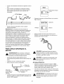
Add Gasoline
,_
DANGER!
NEVER
fill fuelengine
tank indoors.
NEVER
fill fuel
tank when
is running or
hot. DO NOT light a cigarette or smoke when
filling the fuel tank.
,_
DANGER!
Do expansion.
not overfill the fuel tank. Always
leave
room for
•
Use regular UNLEADED gasoline in the
generator. DO NOT use premium gasoline. DO
NOT mix oil with gasoline. DO NOT overfill the gas
tank.
•
Clean area around fuel fill cap; remove cap.
Fillfueltankwithclean,fresh,unleadedgasoline.
Becarefulnotto overfill.Allowabout1/2"tank
spaceforfuelexpansion.
1/2"AirSpace
Place the Run/Stop Switch in the "Run" position.
IGNITION
Tank
RUN
position
Fuel
•
Pull engine choke out to close choke. DO NOT
FORCE. If the engine is warm, you may not need
as much choking.
Install fuel cap and wipe up any spilled gasoline.
IMPORTANT:
It is important to prevent gum deposits
from forming in essential fuel system parts such as the
carburetor, fuel filter, fuel hose or tank during storage.
Also, experience indicates that alcohol-blended fuels
(called gasohol, ethanol or methanol) can attract
moisture, which leads to separation and formation of
acids during storage. Acidic gas can damage the fuel
system of an engine while in storage. To avoid engine
problems, the fuel system should be emptied before
storage of 30 days or longer. See "Storage" on
page 17. Never use engine or carburetor cleaner
products in the fuel tank or permanent damage may
DANGER! Never run engine indoors or in
enclosed poorly ventilated areas. Engine
exhaust contains carbon monoxide, an odorless
and deadly gas.
Occur.
TO START THE ENGINE
_
ARNING!
Neverplugged
start orinto
stoptheengine
electrical
devices
panel with
receptacles and turned on.
•
Unplug all electrical loads from generator
receptacles before starting the engine.
•
Make sure the unit is in a level position.
•
Open the fuel shut-off valve.
t
_
areas
ANGER!
may exceed
Temperature
150°F (65°C).
of muffler
Avoid
and these
nearby
areas on the generator.
Electric
Starting
•
Press the Run/Stop switch to the "RUN" position,
Press the electric start button, located on the
generator cradle opposite the control panel, until
engine cranks.
•
Use short starting cycles (15 sec. per min.) to
prolong starter life. Extended cranking can damage
starter motor.
Turn Clockwise to
"OFF" Position
,_
•
Locate the idle control on/off switch on the control
panel and set it to the "Off" position.
•
When the engine starts, OPEN the choke gradually
as engine warms up up by pushing in on the choke
handle.
•
Set the idle control on/off switch to the "On"
position.
IDLE
OFF
position
J
WARNING!
starting operate
the engine
the with
electric
starter,If always
the with
engine
the battery connected. This ensures that the
battery will be recharged.
Manual Starting
•
Grasp starter grip handle and pull slowly until you
feel some resistance. Then pull cord out with rapid
full arm stroke. Let rope return slowly. Do not let
rope "snap back" against starter. Repeat, if
necessary, with choke opened slightly.
•
When engine starts, OPEN the choke gradually as
the engine warms up by pushing in on the choke
handle.
•
Set the idle control on/off switch to the "On"
position.
IMPORTANT:
Do not overload the generator. Also, do
not overload individual panel receptacles. These
outlets are protected against overload with push-toreset-type circuit breakers. If amperage rating of any
circuit breaker is exceeded, that breaker opens and
electrical output to that receptacle is lost. Read "Don't
Overload the Generator" on page 12 carefully.
STOPPING
•
•
•
•
•
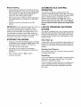
AUTOMATIC
OPERATION
This switch is designed to greatly improve fuel
economy. When this switch is turned "On", the engine
will only run at its normal high governed engine speed
when an electrical load is connected. When an
electrical load is removed, the engine will run at a
reduced speed. With the switch "Off," the engine runs
at the normal high engine speed all the time. Always
have the switch off when starting and stopping the
engine.
LOW OIL PRESSURE
SYSTEM
Let engine run at no-load for 30 seconds to
stabilize the internal temperatures of engine and
generator.
Move run/stop switch to "Stop" position.
Close the fuel valve.
SHUTDOWN
The engine is equipped with a low oil pressure
that shuts down the engine automatically when
pressure drops below 6 psi. If the engine shuts
by itself and the fuel tank has enough gasoline,
engine oil level.
THE ENGINE
Unplug (or turn OFF) all electrical loads connected
to generator panel receptacles. Never start or stop
engine with devices plugged in and turned on.
Turn "Off" the idle control switch.
IDLE CONTROL
sensor
the oil
down
check
Initial Start-up
A delay built in the low oil shutdown system allows oil
pressure to build during starting. The delay allows the
engine to run for about 10 seconds before sensing oil
pressure.
Sensing
Low Pressure
If the system senses low oil pressure during operation,
the engine shuts down.
Restarting
If you try to restart the engine within 10 seconds after it
shuts down, the engine may NOT start. The system
needs 5 to 10 seconds to reset.
If you do restart the engine after such a shutdown and
have not corrected the low oil pressure, the engine
runs for about 10 seconds as described above and
then stops.
10
CHARGING
A BATTERY
DANGER! Storage batteries give off explosive
hydrogen gas while recharging. An explosive
mixture will remain around the battery for a long
time after it has been charged. The slightest
spark can ignite the hydrogen and cause an
explosion. Such an explosion can shatter the
battery and cause blindness or other serious
injury.
,_
To recharge 12 Volt batteries, proceed as follows:
•
If necessary, clean battery terminals.
•
Connect battery charge cable connector plug to
panel receptacle identified by the words
"12-VOLT D.C."
•
Connect battery charge cable clamp with red
handle to the positive (+) battery terminal.
12 VOLT D.C.
RECEPTACLE
RED wire
DANGER!
not permit
open flame,
sparks
or anyDoother
source smoking,
of heat around
a
battery. Wear protective goggles, rubber apron
and rubber gloves when working around a
battery. Battery electrolyte fluid is an extremely
caustic sulfuric acid solution that can cause
severe burns. If spill occurs, flush area with
clear water immediately.
Your generator has the capability of recharging a
discharged 12 Volt automotive or utility style storage
battery. Do not use the unit to charge any 6 Volt
batteries. Do not use the unit to crank an engine
having a discharged battery.
•
•
Check fluid level in all battery cells. If necessary,
add ONLY distilled water to cover separators in
battery cells. Do not use tap water.
If the battery is equipped with vent caps, make sure
they are installed and are tight.
f
+
POS
Black wire
NEG
•
Connect battery charge cable clamp with black
handle to the negative (-) battery terminal.
•
Start engine. Let the engine run while battery
recharges.
•
When battery has charged, shut down engine.
NOTE: Use an automotive hydrometer to test battery
state of charge and condition. Follow the hydrometer
manufacturer's instructions carefully. Generally, a
battery is considered to be at 100% state of charge
when specific gravity of its fluid (as measured by
hydrometer) is 1.260 or higher.
11
DON'T OVERLOAD
GENERATOR
THE
Overloading a generator in excess of its rated wattage
capacity can result in damage to the generator and to
connected electrical devices. Observe the following to
prevent overloading the unit:
Some electric motors, such as induction types,
require about three times more watts of power for
starting than for running. This surge of power lasts
only a few seconds when starting such motors.
Make sure you allow for this high starting wattage
when selecting electrical devices to connect to your
generator:
•
Add up the total wattage of all electrical devices to
be connected at one time. This total should NOT be
greater than the generator's wattage capacity.
1.
Figure the watts needed to start the largest
motor.
2.
•
The rated wattage of lights can be taken from light
bulbs. The rated wattage of tools, appliances and
motors can usually be found on a data plate or
decal affixed to the device.
Add to that figure the running watts of all other
connected loads.
•
•
If the appliance, tool or motor does not give
wattage, multiply volts times ampere rating to
determine watts (volts x amps = watts).
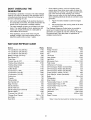
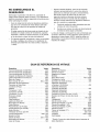
WATTAGE
REFENCE
The Wattage Reference Guide below is provided to
assist you in determining how many items your
generator can operate at one time. (NOTE: All figures
are approximate. See data plate on appliance for
wattage requirements.)
GUIDE
Device ..............................
*Air Conditioner (12,000 Btu) ..............
*Air Conditioner (24,000 Btu) ..............
*Air Conditioner (40,000 Btu) ..............
Battery Charger (20 Amp) ..................
Belt Sander (3") ........................
Chain Saw ............................
Circular Saw (6-1/2") ...............
*Clothes Dryer (Electric) ..................
*Clothes Dryer (Gas) .....................
*Clothes Washer ........................
Coffee Maker ..........................
*Compressor (1 HP) .....................
*Compressor (3/4 HP) ....................
*Compressor (1/2 HP) ....................
Curling Iron .............................
*Freezer ...............................
*Dehumidifier ...........................
Disc Sander (9") ........................
Edge Trimmer ...........................
Electric Blanket ..........................
Electric Nail Gun ........................
Electric Range (per element) ..............
Electric Skillet ..........................
*Furnace Fan (3/5 HP) ....................
*Garage Door Opener ...............
Hair Dryer .............................
Hand Drill ........................
Watts
1700
3800
6000
500
1000
1200
Device ..............................
450
500
1200
*Jet Pump .............................
Lawn Mower ...........................
800
1200
Light Bulb ..............................
Microwave Oven ..................
*Milk Cooler ...........................
Oil Burner on Furnace ....................
800 to 1000
5750
700
1150
1750
2000
1800
1400
700
700
650
1200
500
400
1200
Watts
Hedge Trimmer .........................
Impact Wrench ..........................
Iron ..................................
100
700 to 1000
1100
300
Oil Fired Space Heater (140,000 Btu) .........
Oil Fired Space Heater (85,000 Btu) ..........
Oil Fired Space Heater (30,000 Btu) ..........
*Paint Sprayer, Airless (1/3 HP) .............
Paint Sprayer, Airless (handheld) ............
Radio .............................
50 to
400
225
150
600
150
200
*Refrigerator ............................
Slow Cooker ............................
700
200
*Submersible Pump (1-1/2 HP) .............
2800
*Submersible Pump (1 HP) ................
2000
*Submersible Pump (1/2 HP) ..............
1500
*Sump Pump .....................
800 to 1050
*Table Saw (10") .................
1750 to 2000
Television ........................
200 to 500
Toaster ........................
1000 to 1650
Weed Trimmer ..........................
500
1500
1250
875
500 to 750
1200
250 to 1100
* Allow 3 times the listed watts for starting these devices.
12
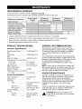
MAINTENANCE
SCHEDULE
Follow the hourly or calendar intervals, whichever occurs first.
More frequent service is required when operating in adverse conditions noted below.
Maintenance Operation
Check Oil Level
Service Air Pre-Cleaner
Every 8 Hours
or Daily
X
25 Hours or
Every Season
x**
I
100 Hours or
Every Season
.....
X*
X
X
Changer Oil And Oil Filters
Clean Spark Arrestor Screen
Adjust Valve Clearance
Retorque Head Bolts
Service Air Cleaner
Replace Spark Plugs
*
50 Hours or
Every Season
X_
X**
X
Change oil after first 8 hours of operation then after every 50 hours or every season.
Change oil and oil filter every 25 hours when operating under heavy load or in high temperatures.
** Clean more often under dirty or dusty conditions. Replace cleaner parts if very dirty.
*** Retorque head bolts only after the first 50 hours.
PRODUCT
Generator
SPECIFICATIONS
GENERAL
The generator warranty does not cover items that
have been subjected to operator abuse or negligence.
To receive full value from the warranty, the operator
must maintain the generator as instructed in this
manual.
Specifications
Rated Maximum Power ................ 10,000 Watts (10.0
kW)
Surge Power ................................. 12,500 Watts (12.5
kW)
Rated AC Voltage ......................... 120/240 Volts AC
Rated Maximum AC Load Current
Some adjustments will need to be made periodically to
properly maintain the generator. All adjustments in the
Service and Adjustments section of this manual should
be made at least once each season. Follow the
requirements in the "Maintenance Schedule" chart
above.
at 240 Volts ................................ 41.7 Amperes
at 120 Volts ................................ 83.3 Amperes
Rated Frequency .......................... 60 Hz at 3600 rpm
Phase Single Phase
Rated DC Voltage ......................... 12 Volts
Rated Maximum DC Load Current
NOTE: Once a year you should clean or replace the
spark plug and replace the air filter. A new spark plug
and clean air filter assure proper fuel-air mixture and
help your engine run better and last longer.
at 12 Volts .................................. 10.0 Amperes
Engine
RECOMMENDATIONS
GENERATOR
Specifications
MAINTENANCE
Generator maintenance consists of keeping the unit
clean and dry. Operate and store the unit in a clean
dry environment where it will not be exposed to
excessive dust, dirt, moisture or any corrosive vapors.
Cooling air slots in the generator must not become
clogged with snow, leaves, or any other foreign
material.
Rated Horsepower ........................ 19 at 3600 rpm
Displacement ................................ 570 cc
Spark Plug
Type: ................................. Champion RC12YC or
Equivalent
Set Gap To: ....................... 0.030inch (0.76mm)
Set Torque To: .................. 200 in-lbs (22.5 N-m)
Gasoline Capacity ......................... 10 U.S. gallons
Oil Type:
Summer ............................. SAE 30 or 10W-30
Check the cleanliness of the generator frequently and
clean when dust, dirt, oil, moisture or other foreign
substances are visible on its exterior surface.
_
Winter ................................ Synthetic 5W-20 or
5W-30
13
CAUTION!
Never
insert
any even
objectif the
or tool
through
the air
cooling
slots,
engine
is not running.
NOTE:DONOTusea gardenhosetoclean
generator.
Watercanentertheenginefuelsystemand
causeproblems.Inaddition,ifwaterentersthe
generator
throughcoolingair slots,somewaterwill be
retainedin voidsandcracksoftherotorandstator
windinginsulation.
Wateranddirtbuilduponthe
generatorinternalwindingswilleventually
decrease
the insulationresistance
of thesewindings.
5. Remove the oil fill cap and insert a clean funnel
into the cap opening. Slowly fill the crankcase with
the recommended oil until the oil level is at the
FULL mark.
To Clean the Generator:
6. When the crankcase is filled to the proper level,
install and tighten the oil fill cap.
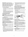
Replacing
the Spark Plugs
•
Use a damp cloth to wipe exterior surfaces clean.
•
A soft, bristle brush may be used to loosen caked
on dirt, oil, etc.
Use the recommended spark plugs set to the correct
air gap [0.76 mm (0.030 in.)]. Replace the plugs
every 100 hours of operation or once each year,
whichever comes first. This will help your engine to
start easier and run better.
•
A vacuum cleaner may be used to pick up loose
dirt and debris.
1. Stop the engine and pull the spark plug wires off of
the spark plugs.
•
Low pressure air (not to exceed 25 psi) may be
used to blow away dirt. Inspect cooling air slots
and openings on the generator. These openings
must be kept clean and unobstructed.
2. Clean around the spark plugs and remove them
from the cylinder head.
3. Set the spark plugs' gap to 0.76 mm (0.030 in.).
Install the correctly gapped spark plugs into the
cylinder heads.
ENGINE MAINTENANCE
,_
DANGER!
When working
the from
generator,
always
disconnect
negative on
cable
battery.
Also disconnect spark plug wires from spark
plugs and keep wires away from spark plugs.
Checking
Oil Level
See the "BEFORE STARTING THE GENERATOR"
section on page 8 for information on checking the oil
level. The oil level should be checked before each
use, or at least every eight hours of operation. Keep
the oil level properly maintained.
Changing
Service
Air Cleaner
Your equipment's air cleaner is one of the most
important areas to maintain. This engine will not run
properly and may get damaged if it is run with a dirty
air cleaner system.
the Oil and Oil Filter
Change the oil and filter after the first eight hours of
operation. Change the oil every 50 hours
thereafter. If you are using this engine under dirty or
dusty conditions, or in extremely hot weather, change
the oil more often.
Clean the foam pre-cleaner every 25 hours of
operation, or sooner under dusty or dirty conditions.
Clean or replace the paper air filter every 50 hours of
operation or once a year, whichever comes first.
Clean or replace the filter more often if the engine is
operated under dusty or dirty conditions.
Use the following instructions to change the oil while
the engine is still warm:
1. Clean the area around the oil drain plug, remove
the plug and drain the oil completely into a suitable
container.
_
2. When the oil is drained, install and tighten the oil
drain plug.
3. Place a suitable container beneath the oil filter and
turn the filter counterclockwise to remove the filter.
CAUTION:
run this
equipment
without
the
complete Never
air cleaner
system
installed
on the
engine. This could result in premature wear to
the engine.
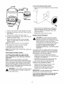
Use the following instructions to clean or replace the
air cleaner components:
1. Remove the cover by loosening both hold-down
straps.
4. Lightly coat the gasket of a new filter with fresh
engine oil. Turn the new filter clockwise until the
gasket contacts the filter adapter, then tighten an
additional 3/4 turn.
2. Slide the foam pre-cleaner off the cartridge.
14
To clean and inspect the spark arrestor:
LATCHES
•
Remove four screws that attach the spark arrestor
screen.
•
4. Squeeze the pre-cleaner dry with a clean cloth. DO
NOT TWIST.
Inspect screen and replace if torn, perforated or
otherwise damaged. DO NOT USE a defective
screen. If screen is not damaged, clean it with
commercial solvent.
•
Reattach the screen with four screws.
5. Prelube the pre-cleaner with clean motor oil.
Engine Governed
_C
KNOB
CARTRIDGE
RETAINER'
ARTRIDGE
I
I
I
I
I
I
I
I
I
FOAM
PRE-CLEANER
HG ISING
3. Wash the pre-cleaner in liquid detergent and water.
Speed
6. Squeeze the pre-cleaner in a clean cloth to remove
excess oil. DO NOT TWIST.
,_
7. Remove the knob and plate. Tap the cartridge
gently on a solid surface to loosen and remove
trapped particles.
NOTE: If the filter is too dirty, it must be replaced.
8. Reinstall the pre-cleaner over the cartridge.
9. Reinstall the air cleaner assembly.
10.Reinstall the plate, knob and cover.
NOTE: If you need to order a new air filter, please call
1-800-366-7278.
Clean Spark Arrestor
Your engine runs at a constant speed. This constant
operating speed is maintained by a mechanical fixed
speed governor. DO NOT try to adjust the governed
speed setting for the following reasons:
Screen
The engine exhaust muffler has a spark arrestor
screen. Inspect and clean the screen every 50
hours of operation or once each year, whichever
comes first.
•
Operating the engine at high engine speeds is
dangerous and increases the risk of personal injury
or damage to the equipment.
• Operating the engine at low engine speeds with
heavy loads may shorten the engine's life.
Incorrect speed settings also affects electrical
operation of your generator as follows:
NOTE: If you use your generator on any forestcovered, brush-covered or grass-covered unimproved
land, it must have a spark arrestor. The spark arrestor
must be maintained in good condition by the owner/
operator. The proceeding is required by the law in the
state of California. Other states may have similar laws.
Federal laws apply on federal lands.
_
CAUTION!
Thefactory
engineand
speed
wasrequire
properly
adjusted at the
should
no
additional adjustment. Do not attempt to change
engine speed. If you believe the engine is
running too fast or too slow, take your engine to
an authorized service center for repair and
adjustment. CHANGING THE ENGINE
GOVERNED SPEED WILL VOID THE ENGINE
WARRANTY.
muffler
coolorbefore
onARNING:
it. Contact Let
withthe
a hot
muffler
engineworking
can
cause severe burns.
•
Operating at high speeds results in an overfrequency and over-voltage condition.
•
Operating at low speeds causes an underfrequency and under-voltage condition.
IMPORTANT:
Incorrect frequency and/or voltage may
damage some connected electrical loads.
If you suspect engine speed is incorrect, take the
generator to an authorized service facility for
repair and adjustment.
15
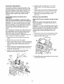
Carburetor
6. Adjust the valve so clearance is 0.1-0.15 mm
(0.004-0.006 in.) for both intake and exhaust
valves.
Adjustments
Your engine carburetor is preset at the factory. The
carburetor should not be tampered with because this
will void the emission control system warranty. If you
experience problems or your engine is used at an
altitude in excess of 5,000 feet, contact the nearest
authorized dealer regarding high altitude setting
changes.
Check/Adjust
Clearance
7. Tighten each lock nut while holding the adjusting
screw. Torque the lock nut to 7 N-m (60 in.-Ibs).
8. Reinstall the valve cover gaskets, valve covers,
seals and nuts. Torque the nuts to 3 N-m
(25 in.-Ibs).
Valve to Rocker Arm
Every 50 hours of operation, remove the rocker
cover and check the valve to rocker arm clearance.
Important: If you feel uncomfortable about doing this
procedure or you don't have the proper tools, please
take your generator in to the nearest service center to
have the valve clearance adjusted. This is a very
important step to insure the longest life for your
engine.
When adjusting the clearance, the engine should be at
room temperature, and each piston should be at top
dead center (TDC) of its compression stroke (both
valves are closed). The correct clearance is
0.10-0.15 mm (0.004-0.006 in.). Check and adjust the
valve to rocker arm clearance as follows:
Retorque
the Head Bolts
After the first 50 hours of operation, retorque the head
bolts.
NOTE: Only perform this adjustment after the first
50 hours of operation. The head bolts will need no
further adjustment.
Important: If you feel uncomfortable about doing this
procedure or you don't have the proper tools, please
take your generator in to the nearest service center to
have the valve clearance adjusted. This is a very
important step to insure the longest life for your
engine.
1. Remove the valve covers as described previously.
2. Torque the head bolts in the sequence shown
below to 19 N-m (165 in.-Ibs).
1. Remove the two nuts and seals from the valve
covers.
SEALING WASHERS
®
2. Remove the valve covers and gaskets.
3. With the spark plugs removed, rotate the crankshaft
until the piston in the cylinder you are checking is at
TDC of its compression stroke (both valves are
closed).
4. Place a caliper end through the spark plug hole and
continue turning the crankshaft until the piston has
moved 1/4 inch past TDC.
CYLINDER
HEAD
=BOLTS
5. Check the valve clearance with a feeler gage
between the valve stem and rocker arm.
®
ADJUSTING
SCREW
5MM
HEX WRENCH
3. Reinstall the valve cover gaskets and valve covers
as described previously.
13MM
WRENCH
LOCK
NUT
®
FEELER
GAUGE
16
GENERAL
•
Disconnect negative battery cable from battery.
The generator should be started at least once every
seven days and allowed to run at least 30 minutes. If
this cannot be done and you must store the unit for
more than 30 days, use the following information as a
guide to prepare it for storage.
•
While engine is still warm, drain oil from crankcase.
Refill with recommended grade.
•
Remove spark plug and pour about 1/2 ounce
(15 ml) of engine oil into the cylinder. Cover spark
plug hole with rag. Pull recoil starter slowly to
distribute oil.
_
DANGER!
store engine
fuel in
tank
indoors NEVER
or in enclosed,
poorlywith
ventilated
areas where fumes may reach an open flame,
spark or pilot light as on a furnace, water
heater, clothes dryer or other gas appliance.
_
LONG TERM STORAGE
It is important to prevent gum deposits from forming in
essential fuel system parts such as the carburetor, fuel
hose or tank during storage. Also, experience
indicates that alcohol-blended fuels (called gasohol,
ethanol or methanol) can attract moisture, which leads
to separation and formation of acids during storage.
Acidic gas can damage the fuel system of an engine
while in storage.
_
•
•
Install and tighten spark plug. Do not connect spark
plug wire.
•
Clean the generator outer surfaces. Check that
cooling air slots and openings on generator are
open and unobstructed.
•
Store the unit in a clean, dry place.
OTHER
To avoid engine problems, the fuel system should be
emptied before storage of 30 days or longer, as
follows:
•
AUTION!
Avoid
spray from spark plug hole
when
cranking
engine.
Remove all gasoline from the fuel tank.
ANGER! away
Drain
fuelopen
into flame.
approved
outdoors,
from
Be container
sure
engine is cool. Do not smoke.
17
TIPS:
•
Do not store gasoline from one season to another.
•
Replace your gasoline can if your can starts to rust.
Rust and/or dirt in your gasoline will cause
problems.
•
If possible, store your unit indoors and cover it to
give protection from dust and dirt. BE SURE TO
EMPTY THE FUEL TANK.
•
Cover your unit with a suitable protective cover that
does not retain moisture.
_
Start and run engine until engine stops from lack of
fuel.
STORAGE
ANGER!
NEVER area
coverare
your
generator while
engine
and exhaust
warm.
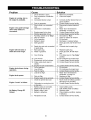
Problem
Engine is running, but no
AC output is available.
Cause
Solution
1.
2.
Circuit breaker is open.
Poor connection or defective
cord set.
Connected device is bad.
1.
2.
Reset circuit breaker.
Check and repair.
3.
4.
1.
2.
Fault in generator.
Short circuit in a connected
load.
Generator is overloaded.
3.
4.
1.
2.
3.
4.
5.
Engine speed is too slow.
Shorted generator circuit.
Run/Stop switch set to "Stop".
Dirty air cleaner.
Out of gasoline.
Battery is dead.
Stale gasoline.
3.
4.
1.
2.
3.
4.
5.
6.
6.
7.
8.
Spark plug wire not connected
to spark plug.
Bad spark plug.
Water in gasoline.
Connect another device that is in
good condition.
Contact Sears service facility.
Disconnect shorted electrical
load.
Read "Don't Overload the
Generator" on page 12.
Contact Sears service facility.
Contact Sears service facility.
Set switch to "Run".
Clean or replace air cleaner.
Fill fuel tank.
Recharge or replace battery.
Drain gas tank and fill with fresh
fuel.
Connect wire to spark plug.
9.
Over choking.
3.
4.
1.
Engine runs good but bogs
down when loads are
connected.
Engine will not start; or
starts and runs rough.
Engine shuts down during
operation.
Engine lacks power.
Engine "hunts"
or falters.
No Battery Charge DC
Output.
10. Low oil level.
11. Excessively rich fuel mixture.
12. Intake valve stuck open or
closed.
13. Engine has lost compression.
1. Out of gasoline.
2. Low oil level.
2.
7.
8.
Replace spark plug.
Drain gas tank; fill with fresh
fuel.
9. Put choke lever to "no choke"
position.
10. Fill crankcase to proper level.
11. Contact Sears Service facility.
12. Contact Sears Service facility.
3.
1.
Fault in engine.
Load is too high.
13.
1.
2.
3.
1.
2.
3.
1.
Dirty air filter.
Engine needs to be serviced.
Choke is opened too soon.
2.
3.
1.
2.
2.
1.
2.
3.
4.
Carburetor is running too rich
or too lean.
Battery posts are corroded.
Battery fluid level is low.
Battery cable is bad.
Battery is defective.
5.
Receptacle is bad.
5.
18
1.
2.
3.
4.
Contact Sears Service facility.
Fill fuel tank.
Fill crankcase to proper level.
Contact Sears service facility.
Read "Don't Overload the
Generator" on page 12.
Replace air filter.
Contact Sears Service facility.
Move choke to halfway position
till engine runs smoothly.
Contact Sears Service facility.
Clean battery posts.
Add distilled water to battery.
Replace cable.
Check battery condition; replace
if defective.
Contact Sears Service facility.
19
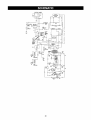
BATTERY
CHARGE
ISA I
--13A
I
TI
?_-I
12V
s'513
/
-__+_2v LI'H-I-II I
_,_ER II
+
--
BATTERY
Y
I
T-
,
Y
II
I
l__
__L
=
6
L_
+
"-'-" FIELD_
,
IOA
I
_o
_
I
c--is_
POWER
._
I
.-oFF
I
IDLE
CUNTRDL
_
i _
I
;_.';-i SVITCH
THROTTLE II
--
_';_gi- I L l_ _11_
_o_"_-'"_l=__
ENG.
E
R
POWER
F
E
_
n
#
lii
i
11
t
2,2
I
44
A
C
_L
,L
i
K A
I _156
_
II t:n_+_LI
22
/
I
G
I I
I
I
I
I
I
I
II*""A"" I-°"N4I
i
+1 /
I
4
I I
_
DO
I-i'--I
I_w,Tc,_
2
12V,lOA
D,o,I I
_
TERMINAL
BLOCK
_RUN
_1;11;11:@_-_45A
_._,
_II_ ts, _.-,-0P
_----o-I,
_T _:-.,,,,,_oo_
SWITCH\
SPARK
QII%
18A
PLUG'"
-)"(#2
ENG,
IGNITION
PLUG
#1
I
I _._-
I
I_$?
I_'T_
' '
V
L_
2 (.
ENG,
_/_22--
I
"020 A
C,'R. /_
22 --
..._-44C--
IGNITION
.A
_. II 4.,I
_O-120V
____
C,B.
?A
20A
/
\',_jla0/240v
11_20/_
_ _
50A
20
44A
BLU
44A
IOA
AUTO
45A
CB,
RESET
CS
0
0
0
120V/30A
12V/IOA
o
o
120/840V
DC
o
5OA
83
@
SYSTEM
CDNTRBL
BOARD
GRN
i8
r
44
CHARGE
RECTiFiER
ii
L
SPARK
PLUG
#i
SPARK
PLUG
#8
GRN
GROUND
BEARING
TO
REAR
CARRIER
21
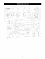
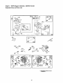
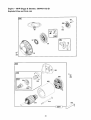
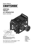
CRAFTSMAN
10000 Watt AC Generator
580.327203
Main Unit m Exploded View
28
50
"_
DETAIL OF ELECTRIC
START SWITCH
29
j31
26
37
58
TO STARTER
k
_TO
39
To
+ TERMINAL
OH BATTERY
Engine
/900
24
_46
22
7
¢
49
48
5O
55 /
17
14
5
To
Motor
Detoil
Battery
of
15
64-
TrGy
To
Stepper
Motor
62
56
65
GROUND
-WIRE TO
ENGINE
62
59
61
\
Throttle
22
L]nkoge
CRAFTSMAN
10000 Watt AC Generator
580.327203
Main Unit m Parts List
Item
1
2
3
4
5
6
7
8
9
10
11
12
13
14
15
16
17
18
19
20
21
22
23
24
25
26
27
28
29
30
31
32
33
34
35
36
37
38
39
40
Part #
Qty
B4653
1
22237
16
22241
8
86292
7
B2758
1
62265
2
22097
9
22127
6
18453621 1
B84650
1
22473
2
45000
2
B44951
1
22261
1
23762
1
18553621 1
38353
8
23152
8
B90916
1
56892
3
NSP
1
B2757
1
73054
1
BB4137
1
B93074
1
78299
1
80270
1
B1696
1
B4325
1
78831B
4
83465
4
22287
2
78289
1
77282
1
18253621 1
18353621 1
96867
1
22129
2
39253
2
79661P
1
Description
ASSEMBLY, Control Panel
LOCK WASHER, 3/8"
NUT, 3/8-16 Hex
SELF DRILLER, 10-16 x 3/4"
DECAL, Control Panel
GROMMET, Rubber
LOCK WASHER, 1/4"
NUT, 1/4"-20 Hex
WIRE ASSEMBLY, Ground
TRAY, Battery
FLAT WASHER, 1/4"
HHMS, 1/4-20" NC x 7"
BRACKET, Hold-Down
SHAKEPROOF, 3/8" Internal
WASHER, #10 Shakeproof
ASSEMBLY, Ground Wire
MOUNTS, Vibration
HHCS, 3/8-16 x 3/4"
HEAT SHIELD, Stator
CRIMPTITE, 10-24 x 3/8"
DECAL, Data Plate
DECAL, Side Panel
DECAL, Fuel Shut Off
CRADLE
SHIELD, Heat
BUSHING, Tank
VALVE, Plastic Tank
TANK, Fuel
CAP, Fuel Gauge
HHCS, M6-1.0 x 60mm
GROMMET, Tank Mounting
HHCS, 1/4"-20 x 3/4"
BRACKET, Starter Switch
SWITCH, Starter
WIRE ASSEMBLY, Starter
WIRE ASSEMBLY, Battery
ASSEMBLY, Stepper Motor
LOCK WASHER, 5/16 -M8
HHCS, M8-1.25 x 20
DECAL, Engine
Item
41
42
44
45
46
47
48
49
50
51
52
53
54
55
Part #
92982
93826
77816
46852
93841
90914
70185
40945
60108
B77304
75246
68548
33141
95921
Qty
1
1
1
2
1
1
1
3
1
2
4
1
1
1
56
57
58
49226
95348
95920
1
1
1
59
60
61
62
63
64
65
66
900
96717
95349
75477
96716
96378
51713
B4901
20566
NSP
1
1
2
3
1
1
1
1
1
Parts Not Illustrated
1
B4659
65787
1
AB3061
2
37806
1
43438
1
93568
1
Optional
23
Description
DECAL, Danger
DECAL, Start Instruction
DECAL, Caution Hot Muffler
TAPTITE, #10-32 x 1/4"
SHIELD, Oil Sensor Heat
ADAPTER, Oil Filter
FILTER, Oil
SHCS, M6-1.0 x 20
SWITCH, Low Oil Pressure
SUPPORT, Engine
TAPTITE, 3/8-16 x 1-1/4"
GASKET, Oil Filter Adapter
HHCS, #10-32 x 3/4"
LINKAGE, Bell Crank to
Throttle
LOCK WASHER, M5
BELL, Crank
LINKAGE, Stepper Motor to
Bell Crank
SPRING, Step Motor Control
PLATE, Idle Control Adjust
PPHMS, M5-0.8 x 20
WASHER, Nylon
SPACER, Step Motor Link
FLAT WASHER, M5
DECAL, 1-800-4-MyHome
DECAL, 1-800
Engine, 19HP, Briggs &
Stratton, 350445-1162-E1
Owners manual
Battery charge cable
Oil, 28oz. SAE 30
120 Volt, 30 Amp locking plug
240 Volt, 30 Amp locking plug
120 Volt, 20 Amp locking plug
Accessories Not Illustrated
09-32688
Cord Wrap Kit
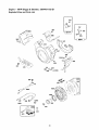
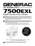
CRAFTSMAN
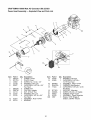
10000 Watt AC Generator
580.327203
Power Head Assembly m Exploded View and Parts List
3
4
9
10
11
\
900
15
5
13
12
5
18
_
14
\
5
17
2O..,
22
Item
2
3
4
5
6
PaN #
B55277
B71791
46852
22129
86307
Qty
1
1
8
11
2
7
8
9
10
11
B55275
BB2700
24114
22237
23152
3
1
4
4
4
12
13
92381
65791
1
1
Item
14
15
Description
GUARD, Center
PLATE, Cover
SCREW, No. 10-32 x 1/4"
WASHER, 5/16" Lock
CAPSCREW, 5/16"-24 x 3/4"
Hex Head
GUARD, Fan
CASTING, Adapter
NUT, 5/16-24" Hex
WASHER, 3/8" Lock
CAPSCREW, 3/8"-16 x 3/4"
Hex Head
ASSEMBLY, Rotor 10-KW
BEARING
16
17
18
19
20
21
22
900
24
Part#
50190
53365
Qty
1
1
B94983
B49410A
77324
1
1
4
B77303
66849A
96423
92769
NSP
1
2
1
1
1
Description
WASHER, 5/16" Flat
CAPSCREW, 5/16"-24 x
10.75" Hex Head
ASSEMBLY, Stator 10-KW
CARRIER, Rear Bearing
CAPSCREW, 5/16"-24 x 12.25
Hex Head
SUPPORT, Alternator
SCREW, M5-0.8 x 20 Taptite
SCREEN, Finger Guard
ASSEMBLY, Power Regulator
Engine, 19HP, Briggs &
Stratton, 350445-1162-E1
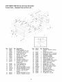
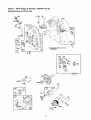
CRAFTSMAN
10000 Watt AC Generator
580.327203
Control Panel m Exploded View and Parts List
33
32
\
31
55
56
f
30
28
11
15
14
15
27.
16
12
10
8
\\\\\\
14
\
\
13
12
lO
5S
1
Item
1
2
3
4
5
6
7
8
9
10
11
Part #
95941
23897
91526
49226
82538
90418
78653
77604
51714
23365
80409
Qty
1
5
4
5
1
1
1
1
2
12
1
12
13
14
15
16
17
18
38150
22264
51715
75207
75207-A
74190
68868
12
16
12
2
2
1
1
19
20
B4455
B4262
2
1
Description
PANEL, Control
FLAT WASHER, #10 - M5
PPHMS, M5-.08 x 12mm
LOCK WASHER, M5
SWITCH, On - Off
OUTLET, 12V DC Snap
SWITCH, Run - Stop
HOURMETER
NUT, M3- 0.5 Hex
WASHER, #8 Shakeproof
OUTLET, 120V, 20 Amp
Duplex GFCI
FLAT WASHER, #8
LOCK WASHER, #8
NUT, M4-0.7 Hex
CIRCUIT BREAKER, 20 Amp
CIRCUIT BREAKER, 30 Amp
OUTLET, 120V/20A locking
OUTLET, 120V, 30 Amp
locking
CIRCUIT BREAKER, 45 Amp
OUTLET, 120/250V, 50 Amp
25
Item
21
Part #
43437
Qty
1
22
23
24
25
26
27
28
29
30
31
32
33
34
35
36
37
38
39
40
80077
92953
96067
84135
87962
43181
43182
84028
93986
94117
93929
79224
65795
B95906
51716
90576
96476
64526
64525
4
1
1
1
1
4
2
1
4
1
4
1
2
1
1
1
1
8
4
Description
OUTLET, 120/240V, 30 Amp
locking
PPHMS, M4 x 20mm
BLOCK, 50 Amp, 3 - Terminal
ASSEMBLY, Engine Harness
GROMMET, Rubber
CIRCUIT BREAKER
PHMS, M3- .05 x 10mm
LOCK WASHER, M3
TRANSFORMER, Idle Control
PPHMS, M3 - 0.5 x 20mm
ASSY., Idle Control
STAND OFF, 1/2" Hex
PPHMS, M5 - 0.8 x 30mm
RECTIFIER, Battery Charge
BOX, Control Panel
NUT M5- 0.8 Hex
GROMMET, Rubber
BOARD, System Control
PHTS, #6-32 x 3/8"
STAND-OFF, 3/4" Hex
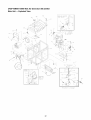
Engine-
19HP Briggs
& Stratton,
350445-1162-E1
Exploded View and Parts List
116
116A
52
51
167
1022
116B
@
©
12
I
358 GASKET SET
52
7
02
167
1033 VALVE OVERHAUL
104
_
Q
2
KIT
1091
117
634A
105
110
_147
_127
634B
634C
26
[121 CARBURETOR
KIT
Engine-
19HP Briggs
& Stratton,
350445-1162-E1
Exploded View and Parts List
351
3O7
_,_---_ 222 a_!
265
I
2271
3Sl _
s6_
280
207
592
208
819_
1 7 305
1014 _
122
529 r-_
_ 467
°_")°
161
535
300
50A
883
307
613 _P_
92134
I
52_
613
93571
I
27
300
Engine-
19HP Briggs
& Stratton,
350445-1162-E1
Exploded View and Parts List
191_]_
95
119
108
104
t
117
194110911
11o
F>
_'_
240
601
1031_
_1030
337 6_
1022
4s_;_
383
_(_171
167
1029
Y1100
166A
868
1100
868
40
_@
I
42
40
_
166A
_4
35
3_3__
915
42
33
REQUIRES SPECIAL TOOLS
TO INSTALL.
28
Engine-
19HP Briggs
& Stratton,
350445-1162-E1
Exploded View and Parts List
461
456 __
58
615
56
55
305
801
802
513
284
803
544
503
29
Engine-
19HP Briggs
& Stratton,
350445-1162-E1
Exploded View and Parts List
727
%
423
526
356
729B
729A
332
334
3O
305
Engine-
19HP Briggs
& Stratton,
350445-1162-E1
Exploded View and Parts List
84
572
524_
614
87
Q 552
8
552A
15
"k REQUIRES
SPECIAL
TO INSTALL.
978
1028_
TOOLS
189
_84
239
982
1027
'92134
243
823 _
@_
116B
26
39
305
_8
31
% 116A
19
1024
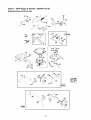
Engine-
19HP Briggs & Stratton,
350445-1162-E1
Exploded View and Parts List
Item
1
2
3
5
5A
7
8
9
10
11
12
13
15
16
17
18
20
22
23
24
25
26
27
28
29
32
33
34
35
37
39
40
42
45
46
50
50A
50B
51
52
53
54
55
56
57
58
59
60
Part #
100-92134
100-85110
67805*
101-92134
102-92134
103-92134*+
104-85110
72315*
105-85110
70596
69336*
69325
67888
104-92134
106-85110
107-85110
108-85110
70540
67924*
109-85110
106-92134
112-85110
107-92134
108-92134
109-92134
110-92134
111-92134
112-92134
113-92134
114-92134
69327
115-92134
119-85110
120-85110
72346
69316
69317
121-85110
102-85109
123-85110
69320
70513
124-85110
70530
125-85110
103-85109
69370
127-85110"
67895*+
128-85110
67158
129-85110
130-85110
131-85110
132-85110
133-85110
134-85110
Description
Cylinder Assembly
Bushing
Seal, Oil
Head, Cylinder #1
Head, Cylinder #2
Gasket, Cylinder Head
Breather Assembly
Gasket, Breather (incl. #722)
Screw, Shoulder
Tube, Breather
Gasket, Crankcase
Screw, Hex
Plug, Oil Drain
Crankshaft
Timing Gear Key
Thrust Washer
Bearing, Ball
Cover, Crankcase
Seal, Oil
Screw, Hex
Flywheel
Key, Flywheel
Piston Assembly (std)
Piston Assembly (.010 o/s)
Piston Assembly (.020 o/s)
Piston Assembly (.030 o/s)
Ring Set (std)
Ring Set (.010 o/s)
Ring Set (.020 o/s)
Ring Set (.030 o/s)
Lock Pin, Piston
Pin, Piston
Rod, Connecting (std)
Rod, Connecting (.020 o/s)
Screw, Hex
Valve, Exhaust
Valve, Intake
Spring, Valve
Guard, Flywheel
Deflector, Oil
Retainer, Valve
Keeper, Valve
Tappet, Valve
Gear, Cam
Manifold, Intake
Manifold, Exhaust (man. start)
Manifold, Exhaust (elec. start)
Gasket, Intake
Gasket
Screw, Hex
HHCS/LW M8-1.25 x 65 mm
Housing, Rewind Starter
Pulley, Rewind Starter
Spring, Rewind Starter
Rope, Starter
Insert, Starter Grip
Grip, Starter Rope
Item
84
87
91
94
95
98
102
103
104
105
108
110
116
116A
116B
117
119
121
122
125
127
130
131
141
147
161
166
166A
167
171
187
188
189
192
201
206
207
208
209
209A
216
216A
222
227
232
239
240
243
265
271
277
277A
280
284
300
304
305
32
Part #
135-85110
68554
118-92134
119-92134@
138-85110
139-85110
140-85110@
79264
141-85110@
142-85110@
120-92134
121-92134@
70506*
68573*
70541*
122-92134@
145-85110
123-92134
124-92134
125-92134
147-85110@
126-92134
127-92134
128-92134
129-92134
86443
70131
151-85110
75253*+
67885+
AA-47662
39253
22129
75254
74946
152-85110
153-85110
154-85110
77348
79282
157-85110
158-85110
130-92134
72320
70125
60108
160-85110
70531
131-92134
161-85110
67884
132-92134
163-85110
39253
164-85110
133-92134
66886
Description
Plug, Pipe
Seal, Governor Shaft
Body Assembly, Upper
Valve, Idle Adjustment
Screw, Slotted
Screw, Idle Speed
Gasket, Carburetor Body
Float, Carburetor
Pin, Float Hinge
Valve, Needle
Valve, Choke
Washer
Seal, O-Ring
Seal, O-Ring
Seal, O-Ring
Jet, Main
Screw, Slotted
Carburetor Kit
Spacer
Carburetor
Plug, Welch
Valve,Throttle
Shaft, Throttle
Shaft, Choke
Jet, Slow Speed
Base, Air Cleaner
Stud, Hex Drive
Stud, Hex Drive
Washer
Nut, Lock M6
Line, Fuel
HHCS M8-1.25 x 20 mm
Washer, Lock 5/16-M8
Screw, Valve Adjust
Link
Nut
Spring, Control Rod
Rod Control
Spring, Governor
Spring, Governor Idler
Link
Rod, Choke
Bracket, Control
Lever, Governor
Spring, Link
Switch, Oil Pressure
Filter, Fuel
Screen, Oil Pump
Clamp, Casing
Lever, Control
Washer, Flat M6
Washer
Bracket, Rod
HHCS M8-1.25 x 20 mm
Muffler, Exhaust
Housing, Blower
HHCS/LW M6-1.0 x 12 mm
Engine-
19HP Briggs & Stratton,
350445-1162-E1
Exploded View and Parts List
Item
307
307A
308
308A
309
310
332
333
334
337
346
351
351A
353
353A
354A
356
356A
357
358
363
383
423
445
455
456
459
461
467
478
503
510
513
515
520
523
524
525
526
529
535
537
539
544
552
552A
562
572
573
592
601
608
613
614
615
616
634
634A
Part #
67898
105-85109
168-85110
169-85110
170-85110
75256
171-85110
67891
72356
72347
134-92134
20169
173-85110
174-85110
175-85110
176-85110
193-85110
137-92134
138-92134
139-92134
177-85110
178-85110
66484
86444
140-92134
180-85110
181-85110
182-85110
86445
212-85110
183-85110
75260
75261
184-85110
185-85110
70158
67181
70151
187-85110
143-92134
188-85110
189-85110"
190-85110
75269
72361
72362
191-85110
70199
192-85110
72321
70162
106-85109
69397
194-85110
195-85110
72367
72365
216-85110@
Description
HHCS/LW M8-1.25 x 16 mm
Screw, Hex
Cover, Air Guide (cyl #1)
Cover, Air Guide (cyl #2)
Motor, Starter
Screw, Hex
Nut, Flywheel
Armature, Magneto
HHCS/LW M4 x 7 mm
Plug, Spark
Screw, Hex
Screw,Phillips Hex
Screw, Hex
Washer, Lock
Washer, Lock
Nut, Hex
Wire, Stop
Wire, Stop
Key, Drive Pulley
Gasket, Set
Flywheel Puller
Wrench, Spark Plug
Screw, Phillips Hex
Filter, Air
Cup, Flywheel
Retainer
Dog, Starter
Screw, Retainer
Knob
Cover, Carburetor
Strap, Starter
Drive, Starter
Clutch, Drive
Spring, Dog
Terminal
Dipstick
Seal, Oil
Tube, Oil Fill
Screw, Phillips Hex
Extension, Breather
Filter, Air
Gasket, Air Cleaner
Clip Rod
Armature, Starter
Bushing, Crank
Bushing, Crank
Bolt, Carriage
Baffle, Breather
Plate, Back
Nut, Hex M6-1.0
Clamp, Hose
Starter, Rewind
HHCS/LW M8-1.25 x 20 mm
Pin, Cotter
Ring, Retaining
Crank, Governor
Washer, Gov. Shaft
Collar, Throttle
Item
634B
634C
635
642
643
657
688
718
722
726
727
729A
729B
741
783
801
802
803
819
823
842
851
862
863
863A
866
868
871
876
883
884
896
915
955
978
982
985
994
1004
1005
1006
1014
1022
1023
1024
1025
1026
1026
1027
1029
1033
1054
1091
1100
*
+
@
33
Part #
Description
197-85110@
Collar, Choke
145-92134@
Seal,Shaft
70562
Boot, Spark Plug
86447
Cover, Air Cleaner
86448
Retainer, Air Filter
67820
Screw, Phillips
198-85110
Cap, Spring
68555
Dowel, Crankcase
sold w/#90NLYO-Ring
200-85110
Gear, Ring
201-85110
Cover, Starter Drive
202-85110
Grommet
203-85110
Clip, Wire
204-85110
Gear, Timing
75264
Gear, Starter
75265
Cap, Drive
205-85110
Cap, End
206-85110
Housing, Starter
68572
HHCS M6-1.0 x 30 mm
70542
HHCS/LW M6 x 16 mm
207-85110
Seal, O-Ring
75272
Terminal, Cable
86449
Strap, Air Cleaner Mounting
107-85109
Bracket, Muffler (man. start)
209-85110
Bracket, Muffler (elec. start)
210-85110
Cover, Air Guide
70122
Seal, Valve Guide
67813
Bushing, Guide
211-85110
Kit, Gear
67897*+
Gasket, Exhaust
213-85110
Clamp
214-85110
Pin, Roll
67195
Liner, Port
147-92134
Plug
68548
Gasket, Oil Filter
68527
HHCS/LW M6-1.0 x 20 mm
215-85110
Insulator
217-85110
Arrestor, Spark
218-85110
Duct, Air
148-92134
Fan, Flywheel
149-92134
Retainer, Fan
150-92134
Shield, Carburetor
220-85110*+
Gasket, rocker Cover
69328
Cover, Rocker
70539
Pump, Oil
70536
Spool, Governor
70577
Rod, Push (steel, intake)
80009
Rod, Push (aluminum,
exhaust)
222-85110
Filter, Oil
224-85110
Arm, Rocker
101-93571
Kit, Valve Overhaul
227-85110
Tie, Cable
229-85110@
Cap, Limiter
230-85110
Pivot, Rocker, Arm
Included in Gasket Set (139-92134)
Included in Valve Overhaul Kit (101-93571 )
Included in Carburetor Kit (123-92134)
CALIFORNIA AND FEDERAL EMISSION CONTROL
WARRANTY STATEMENT
Your Warranty
Warranty
Rights and Obligations
The California Air Resources Board (CARB), United States
Environmental Protection Agency (EPA), and Sears Roebuck and
Co. USA (Sears) are pleased to explain the emissions control
system warranty on your 1997 and later "utility and lawn and
garden equipment engine" (referred to as 'engine'). New engines
must be designed, built, and equipped to meet both the State of
California and Federal stringent anti-smog standards. Sears must
warrant the emission control system on your engine for the periods
of time listed below provided there has been no abuse, neglect, or
improper maintenance of your engine.
Diagnosis
When the engine is inspected by an authorized Sears service
center, the owner shall not be held responsible for diagnostic costs
if the repair is deemed warrantable.
The emissions control system may include parts such as the
carburetor, ignition and exhaust systems. When a warrantable
condition occurs, Sears will repair your engine at no cost to you.
Expenses covered under warranty include diagnosis, replacement
parts and labor.
Manufacturer's
Warranty
Owner's
Warranty
Consequential
Damages
Sears may be liable for damages to other engine components
caused by the failure of a warranted part if the failed part was still
under warranty.
Coverage
The 1997 and later engines are warranted
emission related component or system on
below) is found to be defective, repairs or
performed by an authorized Sears service
Period
Any warranted part which is not scheduled for replacement as
required maintenance shall be warranted for 2 years. Any
warranted part which is scheduled only for regular inspection and/or
has instructions to the effect of "repair or replace as necessary"
shall also be warranted for 2 years. Any warranted part which is
scheduled for replacement as required maintenance shall be
warranted either for the period of time up to its first scheduled
replacement, or for 2 years, whichever comes sooner.
What is not covered
for two years. If any
your engine (as listed
replacement will be
center.
Owner
Responsibilities
Any failures caused by abuse, neglect, or improper
will not be covered.
Responsibilities
Add-On
As the engine owner, you are responsible for the completion of all
required maintenance as listed in your factory supplied owner's
manual. For warranty purposes Sears recommends that you retain
all receipts covering maintenance on your engine. However, Sears
cannot deny warranty solely because of the lack of receipts or for
your failure to ensure the completion of all scheduled maintenance.
or Modified
maintenance
Parts
The use of add-on, unauthorized or modified parts constitutes
sufficient reason for denial of submitted warranty repairs. Sears will
not be held liable for repairs of this type.
How to File a Claim
If you have any questions regarding your warranty rights and
responsibilities, you should contact your nearest authorized service
center or call Sears at 1-800-473-7247.
As the engine owner, you should be aware that Sears may deny
any and/or all warranty coverage or responsibility if your engine or
a part/component of it has failed due to abuse, neglect, improper
maintenance, unapproved modifications, or the use of counterfeit
and/or 'grey-market' parts not made, supplied or approved by the
original equipment manufacturer.
Where to get Warranty
Service
Warranty services or repairs shall be provided at all Sears
authorized service centers.
You are responsible for presenting your engine to a Sears
authorized service center as soon as a problem occurs. Warranty
repairs should be completed in a reasonable amount of time, not to
exceed 30 days.
Maintenance,
Parts
If you have any questions regarding your warranty rights and
responsibilities, you should contact your nearest authorized service
center or call Sears at 1-800-473-7247.
Any Sears approved replacement part used in the performance of
any warranty maintenance or repair on emission related parts will
be provided without charge to the owner if the part is under
warranty.
Warranty
Commencement
Date
Replacement
Emission Control Warranty
The warranty period begins on the date the engine is delivered to
the original, end-use purchaser.
1.
and Repair of Emission Related
Parts List
Fuel Metering System:
a. Carburetor assembly
Length
b. Fuel filter
of Coverage
Sears warrants to the initial owner and each subsequent purchaser
that the engine is free from defects in materials and workmanship
which cause the failure of a warranted part for a period of two
years.
2.
a. Intake manifold
b. Air cleaner
3.
What is Covered
Repair or Replacement
Air Induction System:
Catalytic Muffler Assembly
a. Muffler gasket
b. Exhaust manifold
of Parts
4.
Repair or replacement of any warranted part will be performed at
no charge to the owner at an approved Sears service center. If you
have any questions regarding your warranty rights and
responsibilities, you should contact your nearest authorized service
center or call Sears at 1-800-473-7247.
Ignition System
a. Spark plug
b. Ignition module
5.
34
Crankcase Breather Tube
(if so equipped),
including:
35
Garantia .....................................
Reglas de Seguridad ...........................
Montaje .....................................
Funcionamiento .............................
Especiflcaciones del Producto .....................
GARANTIA
36
37
38
39-46
47
LIMITADA
Mantenimiento ..............................
Almacenamiento ...............................
Reparacion de Averias ..........................
Garantia de Emisiones ........................
Como ordenar partes ..................
PARA GENERADORES
PORTATILES
47-50
51
52
53-54
Ultima Pagina
DE LUJO
SEARS le garantiza al comprador original que el alternador y el motor de su generador portatil estara libre de defectos en
materiales y mano de obra en los componentes y por el periodo de tiempo establecido a continuaci6n a partir de la fecha de
compra original. Esta garantia no es transferible y Qnicamente se aplica a generadores portatiles accionados por el motor
garantizado Sears Serie GN.
CLIENTE*
COM ERCIAL*
Alternador
2 afios (2do afio Qnicamente las partes)
1 afio
Motor
2 afios (2do afio enicamente las partes)
1 afio
* NOTA: Para prop6sitos de esta garantia el t6rmino "Uso del Cliente" representa el uso dom6stico residencial y de
emergencia pot parte del comprador original, sin incluir aplicaciones donde la unidad sea usada como fuente de potencia
principal. El t6rmino "Uso Comerciar' representa todos los otros usos, incluyendo alquiler, construcci6n, comercial y para
prop6sitos lucrativos. Una vez el generador haya tenido uso comercial, 6ste sera considerado como un generador para uso
comercial para los fines de esta garantia.
Durante dicho periodo de garantia, SEARS reparara o reemplazar& a su discreci6n, cualquier parte que haya sido
encontrada defectuosa, en examen previo realizado pot SEARS, bajo uso y servicio normal**. Las baterias de arranque no
estan garantizadas pot SEARS. Todos los costos de transporte bajo garantia, incluyendo el envio a la fabric& de ser
necesario, seran responsabilidad del comprador y deberan ser pagados por anticipado. Esta garantia no cubre el
mantenimiento y servicio normal y no se aplica a juegos de generadores, alternador, motor o partes que hayan sido sujetos
a instalaciones o modificaciones incorrectas o no autorizadas, mal uso, negligencia, accidente, sobrecarga, exceso de
velocidad, mantenimiento, reparaci6n o almacenamiento incorrecto que, a juicio de SEARS, afecte negativamente su
funcionamiento y confiabilidad.
** DESGASTE NORMAL: Como con todos los dispositivos mecanicos, los motores necesitan el servicio y reemplazo
peri6dico de las partes para funcionar en buenas condiciones. Esta garantia no cubre reparaciones cuando el uso normal
haya sobrepasado la vida Qtil de una parte o motor.
NO EXISTEN OTRAS GARANTIAS EXPRESAS. SEARS POR MEDIO DE LA PRESENTE DESCONOCE TODAS LAS
GARANTIAS IMPLICITAS, INCLUYENDO, SIN LIMITARSE, A AQUELLAS DE COMERCIALIZACION
Y ADAPTACION
PARA UN PROPOSITO PARTICULAR AL EXTREMO PERMITIDO POR LA LEY. LA DURACION DE CUALQUIER
GARANTIA IMPLICITA QUE NO PUEDA SER DESCONOCIDA, ESTA LIMITADA AL PERIODO DE TIEMPO
ESPECIFICADO EN LA GARANTIA EXPRESA. LA RESPONSABILIDAD LEGAL ES EXCLUIDA POR DANOS
CONSECUENCIALES,
INCIDENTALES O ESPECIALES BAJO CUALQUIERA DE LAS GARANTIAS.
Algunos estados no permiten limitaciones en la duraci6n de las garantias implicitas, o la exclusi6n o limitaci6n de daSos
incidentales o consecuenciales, por tanto las limitaciones o exclusiones anteriormente mencionadas podrian no aplicarse a
usted. Esta garantia le otorga derechos legales especificos; usted podria tener otros derechos, los cuales cambian de
estado a estado.
Para servicio, visite su centro de servicio de garantia autorizado SEARS mas cercano. El servicio de garantia puede ser
Ilevado a cabo Onicamente por un centro de servicio autorizado SEARS. Esta garantia no se podra aplicar para servicio en
otros centros de servicio. Evidencia de la fecha de compra original debera ser presentada en el momento de solicitar el
servicio de garantia.
Sears, Roebuck
and Co., D/817WA,
36
Hoffman
Estates,
IL 60179
•
Opere el generador enicamente en superficies
niveladas y donde no se vaya a exponer a humedad
excesiva, suciedad, polvo o vapores corrosivos.
•
La gasolina es altamente INFLAMABLE y sus vapores
son EXPLOSIVOS. No permita que lumen, que existan
llamas abiertas, chispas o calor a su alrededor cuando
manipule gasolina. Evite regar gasolina sobre un motor
caliente. Cumpla con todas las regulaciones que
requieran almacenamiento y manejo de gasolina.
•
Nunca agregue combustible cuando la unidad est6 en
funcionamiento.
•
No Ilene el tanque de combustible excesivamente.
Siempre permita que exista espacio para la expansi6n
del combustible. Si el tanque esta demasiado Ileno, el
combustible podria rebosarse y caer sobre el motor
caliente y ocasionar un INCENDIO o una EXPLOSION.
•
Nunca almacene el generador con combustible en el
tanque, donde los vapores de la gasolina puedan entrar
en contacto con llamas abiertas, chispas o luces de
piloto (como en hornos, calentadores de agua o
secadoras de ropa). Podrian ocurrir INCENDIOS o
EXPLOSIONES.
•
Los gases del escape del generador contienen gas de
mon6xido de carbono MORTAL. Este gas peligroso, si
se inhala en concentraciones suficientes, puede
ocasionar p6rdida de la consciencia o incluso la muerte.
Unicamente opere este equipo al aire libre donde exista
ventilaci6n adecuada.
•
Deje por Io menos 2 pies de distancia alrededor del
generador, incluso cuando la unidad est6 funcionando
en exteriores, de otra forma podria dafiar la unidad.
Nunca opere la unidad en el interior de habitaciones o
recintos encerrados donde el flujo de aire que entra o
sale de la unidad pueda ser obstruido.
•
Nunca arranque o detenga el motor-generador cuando
tenga cargas el6ctricas conectadas a los tomacorrientes
y los dispositivos conectados est6n ENCENDIDOS.
Arranque el motor y permita que se estabilice antes de
conectar las cargas el6ctricas. Desconecte todas las
cargas el6ctricas antes de apagar el generador.
•
No introduzca objetos a trav6s de las ranuras de
enfriamiento del motor-generador.
•
Nunca opere el generador: en la Iluvia; en
compartimientos encerrados; si se recalientan los
dispositivos el6ctricos conectados; si se pierde la salida
el6ctrica; si se presentan chispas en el motor o
generador; si se observan llamas o humo cuando la
unidad esta funcionando; si la unidad vibra
excesivamente.
BUSQUE ESTE SIMBOLO PARA SENALAR
PRECAUCIONES DE SEGURIDAD
IMPORTANTES. ESTE SIGNIFICA "iATENCION!!!
iESTE ALERTA!!! SU SEGURIDAD ESTA EN
PELIGRO."
iPELIGRO!
Este generador esta diseSado para
uso en exteriores Qnicamente. No use este
generador en el interior de ninguna edificaci6n o
recinto cerrado, incluyendo el compartimiento para
generador de un vehiculo recreacional (VR).
Podrian ocurrir incendios o explosiones. Las
modificaciones realizadas pot el usuario, incluyendo
ventilaci6n del escape y/o ventilaci6n de
enfriamiento, no eliminaran el peligro. Tambi6n,
permita que exista al menos dos pies de distancia
alrededor del generador, incluso cuando est6
operando la unidad en exteriores.
iPRECAUClON!
Siempre desconecte el alambre
de la bujia y col6quelo donde no pueda entrar en
contacto con la bujia, para evitar el arranque
accidental durante la instalaci6n, transporte, ajuste
o reparaci6n de su generador.
•
•
El generador produce un voltaje muy alto, el cual puede
ocasionar descargas el6ctricas extremamente
peligrosas. Evite el contacto con terminales, alambres
pelados o sin recubrimiento, etc. Nunca permita que
personas no calificadas operen o proporcionen servicio
al generador.
Nunca manipule dispositivos o cordones el6ctricos
cuando se encuentre parado en agua, descalzo o con
los pies o las manos mojadas. Podrian ocurrir
descargas el6ctricas peligrosas.
•
El C6digo EI6ctrico Nacional exige que el bastidor y las
partes externas conductoras de electricidad del
generador est6n conectadas adecuadamente a una
conexi6n a tierra fisica. Los c6digos el6ctricos locales
tambi6n pueden exigir la conexi6n a tierra adecuada del
generador. Consulte con un electricista local para los
requisitos de conexi6n a tierra en su Area.
•
Use un interruptor de circuito de falla a tierra en Areas
hemedas o de alta conductividad (como en pisos
metalicos o estructuras de acero).
•
No utilice
que est6n
cualquier
el6ctricos
el6ctricas
NOTA: Su generador esta equipado con un silenciador
apagachispas. El apagachispas debera ser mantenido en
buenas condiciones de trabajo por parte del
propietario/operador.
La ley en el Estado de California
exige el uso del apagachispas (Secci6n 4442 del C6digo de
Recursos PQblicos de California). Otros estados pueden
tener leyes similares. Las leyes federales se aplican en
tierras federales.
en el generador juegos de cordones el6ctricos
desgastados, pelados, raidos o dafiados de
manera. El uso de juegos de cordones
defectuosos puede ocasionar descargas
o dafios al equipo y/o a la propiedad.
37
Su generador requiere de cierto ensamble y estara listo para
ser usado despu6s de haberle dado un servicio adecuado
con el aceite y el combustible recomendados.
Si tiene problemas con el montaje de su generador, por
favor Ilame a la Linea de Ayuda del Generador al
1-800-222-3136.
IMPORTANTE: Cualquier intento de poner en marcha al
motor antes de darle el servicio con el aceite recomendado
resultara en falla del motor.
PARA RETIRAR
DE LA CAJA
EL GENERADOR
•
Coloque la caja entarimada sobre una superficie plana y
s61ida.
•
Corte con cuidado las bandas a que estan alrededor de
la caja de envio.
•
Levante la caja del generador.
•
Retire todo el material de protecci6n, material de relleno,
etc.
•
Retire el generador de la tarima de envio.
CONTENIDO
Conecte el cable rojo de la bateria al interruptor del
arrancador del motor.
DE LA CAJA
Conecte el cable
rojo de la bateria
a esta conexion
en el interrupter
del arrancador
el_ctrico.
Revise todo el contenido. Si alguna parte falta o esta
dafiada, Ilame a la Linea de Ayuda del Generador al
1-800-222-3136.
•
Generador de 10.000 Vatios
•
Cables de Carga de la Bateria
•
3 Tapones de Aseguramiento
•
Manual del Propietario
•
Aceite para motor
•
Componentes
o
DEL SOPORTE
•
Conecte el cable negro de la bateria al motor utilizando
el perno M8 x 1.25 pulgadas.
Y
Conecte el _
cable negro de
la bateria aqui
utilizando el
perno M8 x
1.25
NOTA: Se le puede dar marcha al generador manualmente.
Si decide no utilizar la caracteristica del arranque el6ctrico
de este generador, usted no tendra que instalar la bateria.
Debera comprar e instalar una bateria de 12 Voltios DC
Sears DieHard 28-27135). Debera darle servicio a la bateria
usando el liquido electr61ito indicado y debera estar
completamente cargada antes de la instalaci6n.
INSTALE LA BATER[A
SlGUlENTE MANERA:
•
Conecte el cable rojo de la bateria del interruptor del
arrancador el6ctrico al terminal positivo (+) de la bateria.
del soporte de la bateria
INSTALACION
BATERIA
•
•
\
DE LA
A
Encuentre los sujetadores de la bateria y los alambres
enviados sueltos en la caja. Encontrara: pernos de 7",
arandelas de seguridad, arandelas, soporte para bateria
y tuercas hexagonales. Ademas debera tener un perno
M8 x 1.25 pulgadas para conectar el cable negro de la
bateria al motor.
Coloque la bateria sobre el soporte.
38
est6
PRECAUCION!
conectado a laAsegQrese
montura del
demotor
que ely cable
no al negro
armaz6n. Podria dafiar el alambre de conexi6n a
tierra.
•
Conecte el otro extremo del cable negro de la bateria al
terminal negativo (-) de la bateria.
•
Vuelva a revisar todas las conexiones
de que estan en los sitios correctos.
para asegurarse
CONOZCA
SU GENERADOR
Lea este manual
del propietario
con su generador
para familiarizarse
y las reglas
de seguridad
con la ubicaci6n
antes
de los diferentes
de operar
controles
su generador.
Compare
las ilustraciones
y ajustes.
Tanque de Combustible
Valvula de Corte
Interruptor del
de Combustible
/arranque
Cortacircuitos
el6ctrico
(AC)
Depurador de Aire
(en la parte superior
del motor)
Cron6metro
Palanca del
Cebador
Interruptor de
Marcha/Parado
Interruptor de Control
de Marcha en Vacio
Tomacorriente
Silenciador
Apagachispas
de
12 Voltios DC, 10 Amperios
Tomacorriente de
120/240 Voltios AC,
50 Amperios
Tomacorrientes
Doble con
Dispositivo ICFT (GFCl) de
120 Voltios AC, 20 Amperios
Tomacorriente
de
Seguridad de 120 Voltios
AC, 20 Amperios
Tomacorriente de
Seguridad de 120 Voltios
AC, 30 Amperios
Cortacircuitos
(AC) - Cada tomacorriente posee un cortacircuito
para proteger el generador contra sobrecargas electricas. Los
cortacircuitos son del tipo "oprimir para reposicionar".
Cron6metro
- Mide el tiempo del funcionamiento
del motor.
Tomacorriente de Seguridad de 120 Voltios AC, 20 Amperios Suministra alimentaci6n electrica para el funcionamiento de cargas
del motor y herramientas, aparatos especiales e iluminacidn
electrica de 120 Voltios AC, 20 Amperios, monofasica de 60 Hz.
Interruptor
de Control de Mareha en Vacio - El control de marcha
en vacio hace funcionar el motor a velocidades normales (altas)
cuando existe una carga y hace funcionar el motor a velocidades de
marcha en vacio (bajas) cuando no existen cargas. Esta
caracteristica mejora el ahorro de combustible, prolonga la vida del
motor y disminuye el ruido del motor.
Tomacorriente de Seguridad de 120 Voltios AC, 30 Amperios Suministra alimentaci6n electrica para el funcionamiento de cargas
del motor y herramientas, aparatos especiales e iluminacidn
electrica de 120 Voltios AC, 30 Amperios, monofasica de 60 Hz.
Tomacorriente de Seguridad de 120/240 Voltios AC,
30 Amperios - Suministra alimentaci6n electrica para el
funcionamiento de cargas del motor y herramientas, aparatos
especiales e iluminaci6n electrica de 120 y/o 240 Voltios AC,
30 Amperios, monofasica de 60 Hz.
Interruptor de Marcha/Parado - Debera estar en la posicidn "Run"
(Marcha) para darle arranque al motor. Col6quelo en la posicidn
"Stop" (Parado) para detener un motor en funcionamiento.
- Usada cuando se esta dando arranque a un
Tomacorrientes Dobles de 120 Voltios AC, 30 Amperios con
Dispositivo ICFT (GFCI) - Cada uno suministra alimentaci6n
electrica para el funcionamiento de cargas del motor y
herramientas, aparatos especiales e iluminaci6n electrica de
120 Voltios AC, 20 Amperios, monofasica de 60 Hz. Los circuitos
estan protegidos con un dispositivo de interrupci6n de falla a tierra.
Silenciador Apagachispas - El silenciador disminuye el ruido del
motor y esta equipado con una pantalla apagachispas.
Tanque de Combustible
- El tanque tiene una capacidad
galones americanos de gasolina sin contenido de plomo.
Aleta de Conexi6n a Tierra
Tomacorriente de 1201240 Voltios AC, 50 Amperios - Suministra
alimentaci6n electrica para el funcionamiento de cargas de motor o
soldadores de 120/240 Voltios, monofasica de 60 Hertzios a
50 Amperios.
Depurador de Aire - Filtra el aire de entrada a medida que penetra
en el motor.
Palanca del Cebador
motor frio.
Tomacorriente de Seguridad de
120/240 Voltios AC, 30 Amperios
de 10
Tomacorriente de 12 Voltios DC, 10 Amperios - Este
tomacorriente le permite recargar una bateria de almacenamiento
de 12 Voltios DC con el cable de carga para bateria suministrado.
V_lvula de Corte de Combustible
- Usada para detener el
suministro de gasolina al carburador.
39
JUEGOS DE CORDONES Y
ENCHUFES DEL CONECTOR
Tomacorriente
Doble de 120 Voltios
20 Amperios con ICFT (GFCI)
Prueba
con ICFT
Pruebe su toma con ICFT cada mes. Siga estas
instrucciones:
AC,
Oprima el bot6n "TEST" ("PROBAR") negro. El bot6n de
"RESET" ("REAJUSTAR") rojo debera saltarse, Io cual
desconectara la alimentaci6n de la toma. Utilice una
lampara de prueba en cada toma.
Esta es una toma de 120 Voltios con interruptor de circuito
por falla a tierra (ICFT = GFCI), la cual consiste de un par
de tomacorrientes protegidos contra sobrecargas a trav6s
de un cortacircuito con dispositivo de reposici6n de
20 Amperios.
_
lampara de prueba
iPELIGRO!
Si el permanece
bot6n "RESET"
encendida
no salta,
cuando
o si lael
bot6n "RESET" salta, no utilice ninguna toma del
circuito. Llame a un electricista calificado.
2. Si las pruebas del ICFT son buenas, vuelva a activar la
alimentaci6n oprimiendo el bot6n RESET firmemente
hasta que est6 en su posici6n y permanezca asegurado.
Si el ICFT no se reposiciona adecuadamente, no utilice
la toma, Ilame a un electricista calificado.
REAJUSTAR
I RESET I
PROBAR
3. Si el ICFT se dispara por si solo en cualquier momento,
reposicionelo y pruebe la toma. No utilice la toma si el
bot6n de reajuste no se sale cuando oprima el boton de
prueba. Llame a un electricista calificado.
I TESTI
,!
de la Toma
i
Tomacorriente
20 Amperios
de 120 Voltios AC,
Use un enchufe tipo NEMA L5-20 con este tomacorriente.
Conecte un juego de cordones de 3 alambres de 125 Voltios
AC a 20 Amperios (o de mayor capacidad) al enchufe.
Use los tomacorrientes para activar cargas el6ctricas de
120 Voltios AC, monofasicas de 60 Hz que requieran hasta
2400 vatios combinados (2.4 kW) o 20 Amperios de
corriente. Unicamente use juegos de cordones de 3 cables
con conexi6n a tierra de alta calidad, con buen aislamiento y
con capacidad de 125 Voltios a 20 Amperios (o de mayor
capacidad).
Neutro (N)
Mantenga los cordones de extensi6n Io mas corto posible,
preferiblemente menos de 15 pies de largo para evitar la
caida de Voltaje y el posible recalentamiento de los
alambres.
Proteccion
120V
Cargado (H)
De Falla A Tierra
El generador esta equipado con un Interruptor de Circuito de
Falla a Tierra (ICFT = GFCI). Este dispositivo satisface
todos los requisitos de los c6digos federales, estatales y
locales aplicables.
El ICFT protege contra descargas el6ctricas que puedan ser
ocasionadas si su cuerpo se convierte en parte del recorrido
en donde viaja la electricidad para alcanzar tierra. Esto
podria suceder si usted toca un aparato o cord6n "vivo" o si
toca tuberias u otros materiales que tengan conexi6n a
tierra.
NEMA L5-20
Tierra
(Verde)
Utilice este tomacorriente para operar cargas de 120 Voltios
AC, 60 Hz, monofasicas que requieran hasta 2400 vatios
(2.4 kW) de potencia a 20 Amperios. La toma esta protegida
por un cortacircuito con dispositivo de reposici6n de
20 Amperios.
Cuando los dispositivos estan protegidos por un ICFT, la
persona sentira la descarga, pero el ICFT cortara dicha
descarga Io suficientemente rapido como para que una
persona en condiciones de salud normales no presente
lesiones severas por la electricidad.
_
F_
siguientes
de linea
iPELIGRO! situaciones:
El ICFT no(1)Io Descargas
protegera contra
lasa
linea; (2) sobrecargas de corriente o cortocircuitos de
linea a linea. El fusible o el cortacircuito del panel de
distribuci6n debera proporcionar dicha protecci6n.
40
Tomacorriente
30 Amperios
de 120 Voltios
AC,
Tomacorriente
10 Amperios
Use un enchufe tipo NEMA L5-30 con este tomacorriente.
Conecte un juego de cordones de 3 alambres con
capacidad de 125 Voltios AC a 30 Amperios (o mayor) al
enchufe.
_
de 12 Voltios
DO,
Este tomacorriente le permite recargar una bateria de
almacenamiento tipo servicio o automotriz de 12 Voltios
utilizando los cables suministrados para carga de bateria.
Neutro (N)
i
Este tomacorriente no puede recargar baterias de 6 Voltios
y no se puede usar para darle arranque a motores que
tengan la bateria descargada. Vea la secci6n
"Procedimiento de Carga de la Bateria" (pagina 45) antes de
intentar recargar la bateria.
120V
Cargado
(H)
Tomacorriente
50 Amperios
F_
AC,
Utilice un enchufe NEMA 14-50 con este tomacorriente.
Conecte un juego de cordones de 4 alambres con
capacidad de 250 Voltios AC a 50 Amperios al enchufe.
Tierra
(Verde)
N EMA L5-30
de 120/240 Voltios
240 Voltios AC
Utilice este tomacorriente para operar cargas de 120 Voltios
AC, 60 Hz, monofasicas que requieran hasta 3600 vatios
(3.6 kW) de potencia a 30 Amperios. La toma esta protegida
por un cortacircuito con dispositivo de reposici6n de
30 Amperios.
Conexi6n a
Tierra del
Armaz6n
Tomacorriente
30 Amperios
de 120/240
Voltios,
Use un enchufe tipo NEMA L14-30 con este tomacorriente.
Conecte un juego de cordones de 4 alambres con conexi6n a
tierra al enchufe y a la carga que desea. El cord6n debera tener
una capacidad de 250 Voltios AC a 30 Amperios (o mayor).
Y (Vivo)
240V
i
X (Vivo)
AC
W (Neutro)
NEMA 14-50
Utilice este tomacorriente para operar cargas el6ctricas de
240 Voltios AC, 60 Hz, monofasicas que requieran hasta
10,000 vatios (10.0 kW) de potencia.
_
Utilice este tomacorriente para operar cargas de 120 Voltios
AC, 60 Hz, monofasicas que requieran hasta 3600 vatios
(3.6 kW) de potencia a 30 Amperios o cargas de 240 Voltios
AC, 60 Hz, monofasicas que requieran hasta 7200 vatios
(7.2 kW) de potencia a 30 Amperios. La toma esta protegida
por un cortacircuito con dispositivo de reposici6n de
30 Amperios.
41
PRECAUCION!
A pesar
de AC
quea esta
toma tiene
una
capacidad de 240
Voltios
50 Amperios
(hasta 12,500 vatios), el generador tan solo tiene una
capacidad de 10,000 vatios. Las cargas de potencia
que excedan la capacidad de vatiaje/amperaje del
generador pueden daSarlo o causar lesiones
severas.
COMO USAR SU GENERADOR
ANTES DE DARLE ARRANQUE
GENERADOR
Si tiene problemas operando su generador, por favor Ilame
a la linea de ayuda para generadores al 1-800-222-3136.
Conexion
a Tierra
Para operar el motor, debera colocar gasolina y aceite de
motor en el generador:
del Generador
ASada Aceite al Motor
El Codigo Eldctrico Nacional exige que el bastidor y las
partes externas conductoras de electricidad de este
generador se encuentren conectadas adecuadamente a
una tierra fisica aprobada. Los c6digos el6ctricos locales
tambi6n podrian exigir la conexi6n a tierra de la unidad.
Para tal prop6sito, se ha suministrado una aleta de conexi6n
a tierra en la base del armaz6n.
NOTA: Cuando aSada aceite a la caja del cig0eSal del
motor en el futuro, 0nicamente use aceite detergente de alta
calidad con la clasificaci6n de servicio SF o SG de API. No
use aditivos especiales.
Seleccione el grado de viscosidad del aceite de acuerdo con
la temperatura de funcionamiento que espera tener:
_F -20
'c. 0
0
-2'0
20
32 40
-i0
Temperaturas
Aleta de Conexi6n a Tierra
Por Io general, la conexi6n de un alambre de cobre trenzado
No. 12 AWG (American Wire Gauge) a la aleta de conexi6n
a tierra y a una barra de conexi6n a tierra de cobre o bronce
(electrodo) proporciona una protecci6n adecuada contra las
descargas el6ctricas. Sin embargo, los c6digos locales
pueden variar substancialmente. Consulte con un
electricista local para conocer los requisites de
conexion a tierra de su area.
de Cargas
Deje que el motor se estabilice y se caliente por unos
minutos despu6s del arranque.
•
Enchufe y encienda las cargas el6ctricas de 120 o
240 Voltios, monofasicas de 60 Hertzios.
•
NO conecte cargas de 240 Voltios a tomacorrientes
120 Voltios.
•
NO conecte cargas trifasicas al generador.
•
NO conecte cargas de 50 Hz al generador.
•
Sume los vatios asignados (o amperios) de todas las
cargas que se van a conectar al mismo tiempo. Este
total no debe ser mayor que (a) la capacidad del
vatiaje/amperaje nominal del generador o (b) la
capacidad del cortacircuito del tomacorriente que
suministre la alimentaci6n. Vea "No Sobrecargue el
Generador" en la pagina 46.
60
80
100
1'0
40
de USOEsperadas
•
Per encima de 40F, use SAE 10W-30 o SAE 30.
•
Por debajo de 40F, use sint6tico 5W-20 o 5W-30.
•
Coloque el generador sobre una superficie nivelada.
•
Limpie el area alrededor del Ilenado de aceite y retire la
tapa y la varilla de medici6n.
•
Limpie la varilla de medici6n.
•
Llene el motor usando la abertura de Ilenado del aceite
hasta que Ilegue a la marca de Ileno ("full") de la varilla
de medici6n. Det6ngase y revise peri6dicamente el nivel
del aceite. NO LLENE EXCESIVAMENTE.
El_ctricas
•
6
A pesar de que los aceites de m01tiple viscosidad (5W30,
10W30, etc.) mejoran el arranque en clima frio, estos
pueden producir un aumento en el consumo de aceite
cuando son usados por encima de 32F. Revise el nivel de
aceite de su motor mas frecuentemente para evitar el
posible daSo del motor debido al funcionamiento del mismo
con un bajo nivel de aceite.
La conexi6n a tierra adecuada del generador ayudara a
evitar las descargas el6ctricas en el caso de que exista una
condici6n de falla a tierra en el generador o en los
dispositivos el6ctricos conectados. La conexi6n a tierra
adecuada tambi6n ayuda a disipar la electricidad estatica, la
cual se acumula frecuentemente en dispositivos no
conectados a tierra.
Conexion
AL
•
Instale la varilla de medici6n. Instale la tapa y aprietela
con la mano firmemente.
•
En adelante, revise el nivel de aceite del motor antes de
cada arranque.
Agregue
de
Gasolina
iPELIGRO!
NUNCA Ilene el tanque del combustible
en recintos cerrados. NUNCA Ilene el tanque del
combustible cuando el motor est6 en funcionamiento
o caliente. NO encienda cigarrillos o fume cuando
est6 Ilenando el tanque del combustible.
,_
combustible. Deje
iPELIGRO!
No Ilene
suficiente
excesivamente
espacio para
el tanque
la
de
expansi6n del combustible.
Use gasolina regular SIN CONTENIDO DE PLOMO en
el generador. No use gasolina premium. NO mezcle
aceite con gasolina. NO Ilene en exceso el tanque de
gasolina.
42
Limpie el Area alrededor del Ilenado de gasolina; retire la
tapa.
f
IDLE
Llene el tanque con gasolina sin contenido de plomo
limpia y nueva. Sea cuidadoso de no Ilenar en exceso.
Deje suficiente espacio para que la expansi6n del
combustible.
1/2" Air Space
MARCHA EN VACIO
J
Tank
Fuel
Coloque el interruptor de Marcha/Parado
"Run" (Marcha).
en la posici6n
f
IGNICION
IGNITION
•
Instale la tapa del combustible
derrame de gasolina.
y limpie cualquier
PARADO
IMPORTANTE: Es importante evitar la formaci6n de
dep6sitos de goma en las partes esenciales del sistema de
combustible como en el carburador, filtro del combustible,
manguera del combustible o tanque, durante su
almacenamiento. Ademas, la experiencia nos dice que los
combustibles con mezclas de alcohol (llamados gasohol,
etanol o metanol) pueden atraer la humedad, la cual
produce la separaci6n y formaci6n de acidos durante el
almacenamiento. La gasolina acida puede daSar el sistema
de combustible de un motor durante su almacenamiento.
MARCH
k.
j
Saque el cebador del motor para cerrarlo. NO LO
FUERCE. Si el motor esta caliente, es posible que no
necesite cebar mucho el motor.
Para evitar problemas en el motor, debera vaciar el sistema
de combustible antes de periodos de almacenamiento de
30 dias o mas. Vea "Almacenamiento" en la pagina 51.
Nunca use productos para limpiar motores o carburadores
en el tanque del combustible; si Io hace ocurriran daSos
permanentes.
PARA DARLE ARRANQUE
MOTOR
_
•
AL
_
recintos
PELIGRO!
encerrados
Nunga ohaga
en Areas
funcionar
cerradas
el motor
con en
poca
ventilaci6n. El escape del motor contiene mon6xido
de carbono, gas inoloro y mortal.
_
Areas
PELIGRO!
vecinas Lapodria
temperatura
exceder del
los silenciador
150°F (65°C)>
y sus
Evite estas Areas.
motor
ADVERTENCIA!
teniendo dispositivos
Nunca arranque
el6ctricos oconectados
detenga el y
encendido en los tomacorrientes del panel.
Desconecte todas las cargas el6ctricas de los
tomacorrientes del generador antes de darle arranque al
motor.
•
Asegt_rese de que la unidad esta nivelada.
•
Abra la valvula de corte de combustible.
t
Valvula del
_
J
Arranque
_
•
Coloque el interruptor
Oprima el interruptor
la base del generador
control, hasta que el
•
Use ciclos de arranque cortos (15 seg. por minuto) para
prolongar la vida del arrancador. El exceso de arranques
puede daSar el motor del arrancador.
Tanque de
"_""""Com
bustible
Girela en este sentido a
Combustible en "-'-'-'_J
; la posici6n "OFF"
posici6n "Open"
("Cerrada")
("Abierta")
•
Localice interruptor de encendido/apagado del control de
marcha en vacio en el panel de control y col6quelo en la
posici6n "Off" (Apagado).
_
43
El_ctrico
de Marcha/Parado en "RUN".
del arranque el6ctrico, ubicado en
al lado opuesto del panel de
motor comience a girar.
arrancador
ADVERTENClA!
el6ctrico, Si
opere
da arranque
el motor alcon
motor
la bateria
con el
conectada. Esto asegura que la bateria va a ser
recargada.
•
Cuando el motor arranque, ABRA el cebador
gradualmente a medida que el motor se calienta
empujando la manija del cebador.
CONTROL AUTOMATICO
MARCHA EN VACiO
•
Coloque el interruptor de encendido/apagado
de marcha en vacio en la posici6n "On".
Este interruptor ha sido diseSado para mejorar el consumo
de combustible. Cuando este interruptor est6 en "On"
(Activado), el motor funcionara Qnicamente en su alta
velocidad de mando normal una vez la carga el6ctrica sea
conectada. Cuando la carga el6ctrica es retirada, el motor
funcionara a una velocidad reducida. Si el interruptor esta
en "Off" (Desactivado), el motor funcionara en alta velocidad
normal. Siempre tenga el interrupter en apagado cuando
arranque y detenga el motor.
Arranque
•
•
•
del control
Manual
Agarre el mango del arrancador y halelo lentamente
hasta que sienta cierta resistencia. Despu6s, hale la
cuerda con un movimiento rapido del brazo. Permita que
la soga se devuelva lentamente. No deje que la soga se
"devuelva rapidamente" y golpee el arrancador. Repita
este procedimiento, si es necesario, con el cebador
ligeramente abierto.
SISTEMA DE APAGADO
PRESION DE ACEITE
Cuando el motor arranque, ABRA el cebador
gradualmente a medida que el motor se calienta
empujando la manija del cebador.
Coloque el interruptor de encendido/apagado
de marcha en vacio en la posici6n "On".
POR BAJA
El motor esta equipado con un sensor de baja presi6n de
aceite que apaga el motor automaticamente cuando la
presi6n del aceite cae por debajo de 6 psi. Si el motor se
apaga por si solo y el tanque de combustible tiene suficiente
gasolina, revise el nivel de aceite del motor.
del control
IMPORTANTE: No sobrecargue el generador. Tampoco
sobrecargue lot tomacorrientes individuales del panel. Estas
tomas estan protegidas contra sobrecarga por los
cortacircuitos tipo oprimir para reajustar. Si excede la
capacidad de cualquier cortacircuito, ese cortacircuito se
abrira y se perdera la salida el6ctrica para ese
tomacorrientes. Lea minuciosamente "No Sobrecargue el
Generador" en la pagina 46.
PARADO
DE
Puesta
en Marcha
Inicial
Una demora previamente incorporada en el sistema de
apagado por baja presi6n aceite permite que la presi6n del
aceite se acumule durante el arranque. La demora permite
que el motor funcione por aproximadamente 10 segundos
antes de detectar la presi6n del aceite.
DEL MOTOR
Deteccion
de Baja Presion
Desconecte (o APAGUE) las cargas el6ctricas
conectadas a los tomacorrientes del panel del
generador. Nunca le de arranque o detenga el motor
teniendo dispositivos conectados y encendidos.
El motor se apagara si el sistema detecta baja presi6n de
aceite durante el funcionamiento.
•
Mueva el interruptor de control de marcha en vacio a la
posici6n "Off".
•
Deje que el motor funcione sin cargas por 30 segundos
para estabilizar las temperaturas internas del motor y el
generador.
Si usted trata de volver a darle arranque al motor a los
10 segundos de haberse apagado, es posible que el motor
NO arranque. El sistema necesita de 5 a 10 segundos para
reajustarse.
•
•
Mueva el interruptor de marcha/parado
"Stop" (Parado).
•
Cierre la valvula del combustible.
Arranques
Sucesivos
Si usted vuelve a darle arranque al motor despu6s de dicho
apagado y no ha corregido el problema de baja presi6n de
aceite, el motor funcionara por aproximadamente
10 segundos, como fue descrito anteriormente, y despu6s
se detendr&
a la posici6n
44
PROCEDIMIENTO
BATERIAS
DE CARGA
DE
iPELIGRO!
Las baterias de acumuladores
producen gas de hidr6geno explosivo cuando son
recargadas. Una mezcla explosiva va a permanecer
alrededor de la bateria por un periodo de tiempo
prolongado despu6s de haber sido cargada. La
chispa mas pequeSa podria encender el hidr6geno y
causar una explosi6n. La explosi6n puede destruir la
bateria y causar ceguera y otras lesiones serias.
,_
•
Si la bateria esta equipada con tapas de desfogue,
aseg6rese de que est6n instaladas y apretadas.
•
Limpie los terminales
•
Conecte el enchufe conector del cable de carga de la
bateria al tomacorrientes del panel identificado con las
palabras "12-VOLT D.C." ("12-VOLTIOS D.C.").
•
Conecte el sujetador del cable de carga de la bateria
que tiene la manija roja al terminal positivo (+) de la
bateria.
TOMACORRIENTE
DE 12 VOLTIOS DC
abiertas,
iPELIGRO!chispas
No permita
o cualquier
que otra
se fume,
fuentellamas
de calor
alrededor de la bateria. Use anteojos de protecci6n,
delantal de caucho y guantes de caucho cuando
trabaje alrededor de la bateria. El liquido electr61ito
de la bateria es una soluci6n de acido sulf6rico
÷
POS
extremadamente caustica, la cual puede causar
quemaduras severas. Si ocurren derrames, limpie
inmediatamente el Area con agua limpia.
NEG
BATERIA DE 12 VOLTIOS
Su generador tiene la capacidad de recargar baterias
descargadas de acumuladores tipo servicio o automotriz de
12 Voltios. No utilice la unidad para cargar baterias de
6 Voltios. No use la unidad para mover motores que
tengan la bateria descargada.
Para recargar baterias de 12 Voltios, Ileve a cabo los
siguientes procedimientos:
•
de la bateria si es necesario.
•
Conecte el sujetador del cable de carga de la bateria
que tiene la manija negra al terminal negativo (-) de la
bateria.
•
Dele arranque el motor. Deje que el motor funcione
mientras la bateria se recarga.
•
Apague el motor cuando la bateria se haya cargado.
NOTA: Use un hidr6metro para autom6viles para probar el
estado de carga y condici6n de la bateria. Siga
cuidadosamente las instrucciones del fabricante del
Revise el nivel del liquido en todas las celdas de la
bateria. Si es necesario, a_ada UNICAMENTE agua
destilada hasta cubrir los separadores de las celdas de
la bateria. No use agua de grifo.
hidr6metro. Por Io general, se considera que una bateria
esta en un estado de carga del 100% cuando la gravedad
especifica de su liquido (medido por el hidr6metro) es de
1.260 o mas.
45
NO SOBRECARGUE
GENERADOR
EL
Algunos motores el6ctricos, como los de inducci6n,
requieren aproximadamente 3 veces mas vatios de
poder para su arranque que para su funcionamiento.
Esta onda irruptiva de poder dura tan solo unos
segundos durante el arranque de dichos motores.
AsegQrese de tenet en cuenta este alto vatiaje de
arranque cuando seleccione los dispositivos el6ctricos
que va a conectar a su generador:
•
Sobrecargar el generador mas alia de su capacidad de
vatiaje puede ocasionar daSos al mismo y a los dispositivos
el6ctricos conectados. Siga las siguientes instrucciones para
evitar sobrecargar la unidad:
•
•
•
Sume el vatiaje total de todos los dispositivos el6ctricos
que van a ser conectados al mismo tiempo. Este total
NO debe ser mayor que la capacidad de vatiaje del
generador.
1.
2.
de todas las otras cargas conectadas.
El vatiaje nominal de las luces puede ser tomado de los
bombillos. El vatiaje nominal de herramientas, aparatos
especiales y motores se puede encontrar, por Io general,
en la calcomania o placa de datos del dispositivo.
La Guia de Vatiaje a continuaci6n ha sido suministrada para
ayudarle a determinar cuando elementos puede operar su
generador al mismo tiempo. (NOTA: todas las cifras son
aproximadas. Vea la placa de datos del aparato para los
requisitos de vatiaje).
Si el aparato especial, herramienta o motor no suministra
el vatiaje, multiplique los voltios pot la clasificaci6n de
amperaje para determinar los vatios (voltios x amperios
= vatios).
GUIA DE REFERENCIA
Dispositivo ............................
*Aire Acondicionado (12.000 BTU) ...............
*Aire Acondicionado (24.000 BTU) ...............
*Aire Acondicionado (40.000 BTU) ...............
Cargador de Baterias (20 Amperios) ...............
Lijadora Automatica de Correa (3") ...............
Sierra de Cadena ...........................
Sierra Circular (6-1/2") ...................
*Secadora de Ropa (EI6ctrica) ..................
*Secadora de Ropa (Gas) ......................
*Lavadora de Ropa ...........................
Cafetera ...................................
*Compresor (1 HP) ...........................
*Compresor (3/4 HP) .........................
*Compresor (1/2 HP) .........................
Pinza para cabello ............................
*Congelador .................................
*Deshumidifacor ..............................
Lijadora de Disco (9") .........................
Recordadora de Bordes ........................
Cobija EI6ctrica ..............................
Pistola EI6ctrica de Puntillas ....................
Cocina EI6ctrica (por homilla) ...................
Sart6n EI6ctrico .............................
*Ventilador de Homo (3/5 HP) ...................
*Control Abrepuertas .....................
Secador de Pelo .............................
Taladro de Mano .......................
Recordadora de Bordes ........................
Llave de Choque .............................
Calcule la cantidad de vatios necesarios para dar
arranque al motor mas grande.
Sumele a ese nQmero los vatios de funcionamiento
Vatios
1700
3800
6000
500
1000
1200
800 a 1000
5750
700
1150
1750
2000
1800
1400
700
700
650
1200
500
400
1200
1500
1250
875
500 a 700
1200
250 a 1100
450
500
DE VATIAJE
Dispositivo ............................
Maquina de Planchar .........................
*Bomba de Chorro ............................
Segadora de C6sped .........................
Bombillo ....................................
Homo Micro-ondas ......................
*Enfriador de Leche ..........................
Quemador de Aceite de Homo ...................
Calentador Alimentado
a Petr61eo (140.000 Btu) ........................
Calentador Alimentado
Vatios
1200
800
1200
100
700 a 1000
1100
300
400
a Petr61eo (85.000 Btu) ........................
225
Calentador Alimentado
a Petr61eo (30.000 Btu) ........................
150
*Rociador de Pintura, Sin Aire (1/3 HP) ............
600
Rociador de Pintura, Sin Aire (de mano) ............
150
Radio ..................................
50 a 200
*Refrigerador ................................
700
Olla de Cocci6n Lenta .........................
200
*Bomba Sumergible (1-1/2 HP) ..................
2800
*Bomba Sumergible (1 HP) .....................
2000
*Bomba Sumergible (1/2 HP) ...................
1500
*Bomba de Pozo ........................
800 a 1050
*Sierra de Caballete (10") ................
1750 a 2000
Televisi6n ..............................
200 a 500
Tostadora ............................
1000 a 1650
Corta Maleza ................................
500
* Permita 3 veces los vatios listados para el arranque de
estos dispositivos.
46
PROGRAMA
DE MANTENIMIENTO
Siga los intervalos horarios o de calendario, Io que ocurra primero. Se requiere de servicio con mayor frecuencia cuando
opere la unidad en las condiciones adversas descritas a continuaci6n.
Cada 8 horas o
diariamente
X
Operacibn
de
Mantenimiento
Revise el nivel del aceite.
Suministre
servicio al
25 horas o cada
estacibn
50 horas o cada
estacibn
100 horas o
cada estacibn
iiiiiiiiiiiiiiiiiiiiiiiiiiiiiiiiiiiiiiiiiiiiiiiiiiiiiiiiiiiiiiiiiiiiiiiiiiiiiiiiiiiiiiiiiiiiiiiiiiiiiiiiiiiiiiiiiiiiiiii
X**
predepurador
de aire.
Cambie el aceite y el filtro
del aceite. ++
X*
Limpie la pantalla del
apagachispas.
Ajuste la separaci6n
de las
valvulas.
iiiiiiiiiiiiiiiiiiiiiiiiiiiiiiiiiiiiiiiiiiiiiiiiiiiiiiiiiiiiiiiiiiiiiiiiiiiiiiii
X
X
Vuelva a apretar los pernos
de cabeza.
Suministre
servicio al
X_
X**
depurador de aire.
Reemplace
la bujias.
++
X
Cambie el aceite despu_s de las primeras 8 horas de operaci6n y despu_s cada 50 horas o cada estaci6n.
Cambie el aceite y el filtro del aceite cada 25 horas cuando opere la unidad bajo cargas fuertes o en altas temperaturas.
Limpie mas a menudo bajo condiciones demasiado sucias o polvorientas. Reemplace las partes del
depurador si est&n muy sucias.
Vuelva a apretar los pernos de cabeza despues de las primeras 50 horas de operaci6n.
ESPECIFICACIONES
PRODUCTO
Especificaciones
Calibrar Separaci6n a: ..........
GENERALES
La garantia del generador no cubre los elementos que
hayan sido sujetos al abuso o negligencia del operador.
Para recibir el valor completo de la garantia, el operador
debera mantener el generador de la forma descrita en este
manual.
10,000 vatios (10.0 kW)
12,500 vatios (12.5 kW)
120/240 Voltios
Se deberan Ilevar a cabo algunos ajustes peri6dicamente
para mantener correctamente su generador.
41.7 Amperios
83.3 Amperios
60Hz a 3600 rpm
Monofasica
12 Voltios
Todos los ajustes de la secci6n Servicio y Ajustes de este
manual deberan ser hechos por Io menos una vez en cada
estaci6n. Cumpla con los requisitos de la tabla "Programa
de Mantenimiento" descrita anteriormente.
NOTA: Una vez al aSo debera limpiar o reemplazar la bujia
y reemplazar el filtro de aire. Una bujia nueva y un filtro de
aire limpio garantizan una mezcla de combustible-aire
adecuada y ayuda a que su motor funcione mejor y tenga
una vida etil mas prolongada.
10.0 Amperios
del Motor
Caballos de Fuerza ............
Desplazamiento ...............
Bujia
Tipo: .......................
Torsi6n: .....................
Capacidad del Tanque
de Gasolina ..................
Tipo de Aceite
Verano ...................
Invierno ..................
RECOMENDACIONES
del Generador
Potencia MAxima ..............
Potencia de Sobretensi6n .......
Voltaje AC Nominal ............
Corriente de Carga MAxima
a 240 Voltios ...............
a 120 Voltios ...............
Frecuencia Nominal ............
Fase .......................
Voltaje DC Nominal ............
Corriente de Carga
MAxima a 12 Voltios ...........
Especificaciones
DEL
19 a 3600 rpm
570 cc
MANTENIMIENTO
GENERADOR
Champion RC12YC o
equivalente
0.030 pulgadas
(0.76mm)
200 pul-lbs (22.5 N-m)
DEL
El mantenimiento del generador consiste en mantener la
unidad limpia y seca. Opere y almacene la unidad en un
ambiente limpio y seco donde no vaya a estar expuesta a
excesos de polvo, suciedad, humedad o a vapores
corrosivos. Las ranuras para aire de enfriamiento del
generador deben permanecer despejadas, sin acumulaci6n
de nieve, hojas u objetos extraSos.
10 galones americanos
SAE 30 o10W-30
Sint6tico 5W-20 o
5W-30
47
Revise frecuentemente la limpieza del generador y limpielo
cuando elementos como polvo, suciedad, aceite, humedad o
substancias extraSas sean visibles sobre su superficie
exterior.
_
1. Limpie el Area alrededor del tap6n para drenaje de
aceite, retire el tap6n y drene el aceite por completo en
un recipiente adecuado.
2. Una vez haya drenado el aceite, instale el tap6n del
drenaje de aceite y apri6telo.
3. Coloque un recipiente debajo del filtro de aceite y gire el
filtro en sentido contrario alas manecillas del reloj para
retirarlo.
herramientas
de las
ranuras
de enfriamiento
iPRECAUClON!a trav6s
Nunca
inserte
objetos
o
de aire, incluso si el motor no esta en
funcionamiento.
4. Recubra el empaque del filtro nuevo con una capa de
aceite de motor. Gire el filtro nuevo en el mismo sentido
NOTA: NO recomendamos el uso de mangueras de jardin
para limpiar el generador. El agua podria introducirse en el
sistema de combustible del motor y causar problemas.
Ademas, si el agua se introduce al generador a trav6s de
las ranuras para aire de enfriamiento, algo del agua quedara
retenida en los espacios vacios y grietas del aislamiento del
devanado del estator y rotor. La acumulaci6n de agua y
suciedad en los devanados internos del generador
disminuira eventualmente la resistencia del aislamiento de
estos devanados.
de las manecillas del reloj hasta que el empaque tenga
un contacto firme con el adaptador del filtro; despu6s
aprietelo 3/4 de vuelta adicional.
5. Retire la tapa del aceite e inserte un embudo limpio en la
abertura. Llene la caja del cigQeSal con el aceite
recomendado hasta que su nivel Ilegue a la marca FULL.
6. Cuando la caja del cigQeSal est6 Ilena al nivel correcto,
instale la tapa y apri6tela.
Para Limpiar el Generador:
Reemplazo
•
Utilice un trapo hQmedo para limpiar las superficies
exteriores.
•
Puede usar un cepillo de cerdas suaves para retirar la
suciedad endurecida, aceite, etc.
Use bujias Champion RC12YC o equivalentes. La
separaci6n correcta es 0.76 mm (0.030 pulgadas).
Reemplace las bujias cada 100 horas de operaci6n o una
vez al aSo, Io que suceda primero. Esto ayudara a su motor
a arrancar mas facilmente y a funcionar mejor.
•
Puede usar una maquina aspiradora
suciedad y residuos sueltos.
•
Puede usar aire a baja presi6n (que no exceda los 25
psi) para eliminar la suciedad. Inspeccione las ranuras
para aire de enfriamiento y la apertura del generador.
Estas aberturas deberan mantenerse limpias y
despejadas.
MANTENIMIENTO
para eliminar
de las Bujias
1. Detenga el motor y saque el alambre de la bujia.
2. Limpie alrededor de las bujias y saquelas de la cabeza
del cilindro.
3. Ajuste la separaci6n de la bujia a 0.76 mm (0.030
pulgadas). Instale las bujias con la separaci6n correcta
en las cabezas de los cilindros.
DEL MOTOR
de
iPELIGRO!
la bateria cuando
Siempre trabaje
desconecte
en el generador.
el cable negativo
Tambi6n desconecte los alambres de la bujia y
mant6ngalos alejados de la misma cuando trabaje en
el generador.
Revision
del Nivel de Aceite
Proporcione
Vea la secci6n "ANTES DE DARLE ARRANQUE AL
GENERADOR" en la pagina 40 para inforci6n en como
revisar el nivel del aceite. El nivel de aceite debera revisarse
al Depurador
ae Aire
El depurador de aire de su equipo es una de las Areas mas
importantes y debera mantenerla en buen estado. Este
motor no funcionara correctamente y podria resultar daSado
si Io hace funcionar con un sistema de depurador de aire
sucio.
antes de cada uso o por Io menos cada ocho horas de
operaci6n. Conserve el nivel de aceite adecuado.
Cambio
Servicio
Limpie el predepurador de espuma cada 25 horas de
operaci6n o mas a menudo si la unidad funciona bajo
condiciones muy polvorientas. Limpie o reemplace el filtro
de aire de papel cada 50 horas de operaci6n o una vez al
aSo, Io que suceda primero. Limpielo o reemplacelo mas a
menudo si el motor funciona bajo condiciones de suciedad o
polvo excesivo.
de Aceite y Filtro del Aceite
Cambie el aceite y el filtro del aceite despu6s de las
primeras ocho horas de operaci6n. Cambie el aceite cada
50 horas de ese momento en adelante. Siesta utilizando su
generador bajo condiciones de extrema suciedad o polvo, o
en un clima demasiado caliente, haga el cambio de aceite
mas frecuentemente.
Siga las siguientes instrucciones
para cambiar el aceite
teniendo el motor todavia caliente despu_s del
funcionamiento:
_
Nunca
haga funcionar
siPRECAUCION!
todo el sistema del
depurador
de aire noeste
estaequipo
instalado en el motor. Esto podria ocasionar el
desgaste prematuro del motor.
48
Siga las siguientes instrucciones para limpiar o
reemplazar los componentes del depurador de aire:
1. Retire la cubierta soltando ambos cerrojos de sujeci6n.
_
.,,..-m,#
2.
Saque el predepurador
de espuma del cartucho,
l
#
SUJETADORES
RETENEDOR
DEL CARTUC
U
#
_._
PERILLAHo_
II
CARTUC
•
/._PRFnFPlIRAnOR
PREDEPURADOR
Inspeccione
la pantalla y reemplacela
siesta
rota,
perforada o en general da_ada. NO use pantallas
defectuosas. Si la pantalla no esta daSada, limpiela con
un disolvente comercial.
DE ESPUMA
•
Vuelva a instalar la pantalla usando los cuatro tornillos.
Velocidad
de Mando del Motor
CAJA
3.
Lave el predepurador en agua y detergente liquido.
4.
Exprima el predepurador hasta que est6 seco en un
trapo limpio. (NO LO RETUERZA).
5.
Lubrique el predepurador
6.
Exprima el predepurador en un trapo limpio para retirar
el exceso de aceite. NO LO RETUERZA.
7.
Retire la perilla y la placa para poder golpear
suavemente el cartucho contra una superficie s61ida y
asi retirar y soltar las particulas atrapadas.
_
con aceite de motor limpio.
Su motor funciona a una velocidad constante.
sobre el cartucho.
9. Vuelva a instalar el conjunto del depurador de aire.
•
Hacer funcionar el motor a velocidades altas es
peligroso y aumenta el riesgo de lesiones personales o
daSo del equipo.
•
Hacer funcionar el motor a velocidades bajas con cargas
pesadas puede acortar la vida del motor.
10. Vuelva a instalar la placa, la perilla y la cubierta.
NOTA: Si necesita ordenar un filtro de aire nuevo, Ilame por
favor al 1-800-366-7278.
Limpie la Pantalla
del Apagachispas
Las calibraciones incorrectas de velocidad tambi_n
afectan el funcionamiento
el_ctrico de su generador de
la siguiente manera:
El silenciador de escape del motor posee una pantalla
apagachispas. Inspeccione y limpie la pantalla cada 100
horas de operaci6n o una vez al aSo, Io que suceda
primero.
•
•
crea una
y sobrevoltaje.
Hacer funcionar el motor a bajas velocidades crea una
condici6n de baja frecuencia y bajo voltaje.
IMPORTANTE: La frecuencia y/o el voltaje incorrecto puede
daSar algunas de las cargas electricas conectadas.
Si sospecha que la velocidad del motor es incorrecta,
Ileve el generador a un centro de servicio autorizado
para su reparacion y ajuste.
Deje enfriar el silenciador antes de manipularlo. El contacto
con un silenciador o motor caliente puede causar
quemaduras severas.
Para limpiar e inspeccionar
Hacer funcionar el motor a altas velocidades
condici6n de sobrefrecuencia
NOTA: El generador debera tener un apagachispas si Io usa
en terrenos no tratados cubiertos de monte, maleza o pasto.
El apagachispas debera ser mantenido en buenas
condiciones por parte del propietario/operador.
Lo anterior
es exiguido por la ley en el estado de California. Otros
estados pueden tener leyes similares. Las leyes federales
se aplican en tierras federales.
•
Esta
velocidad constante de operaci6n es mantenida por un
regulador mecanico de velocidad fija tipo contrapeso. NO
intente ajustar la calibraci6n de la velocidad de mando por
las siguientes razones:
NOTA: Si el filtro esta muy sucio debera reemplazarlo.
8. Vuelva a instalar el predepurador
ajustada
PRECAUCION!
adecuadamente
La velocidad
en la fabrica
del motor
y nofue
requiere
de ajustes adicionales. No intente cambiar la
velocidad del motor. Si cree que el motor esta
funcionando muy rapido o muy lento, Ileve su motor
a un centro de servicio autorizado para reparaci6n y
ajuste. CAMBIAR LA VELOCIDAD DE MANDO DEL
MOTOR CANCELA LA GARANTIA.
el apagachispas:
Retire los cuatro tornillos que estan sujetando la pantalla
del apagachispas.
49
Ajuste
6. Ajuste la valvula de manera que la separaci6n sea de
0.1-0.15 mm (0.004-0.006 pul.) para la valvula de toma y
la de escape.
del Carburador
El carburador de su motor fue ajustado previamente en la
fabrica. No debera manipular el carburador ya que esto
cancelara la garantia del sistema de control de emisiones.
Si tiene problemas o su motor es usado en altitudes
mayores de 5,000 pies, p6ngase en contacto con el
distribuidor autorizado mas cercano para los cambios de
calibraci6n correspondientes para altitudes elevadas.
Revision/Ajuste
de la Separacion
V_lvulas
al Brazo Oscliante
7. Apriete cada tuerca de fijaci6n mientras sostiene el
tornillo de ajuste. Apriete la tuerca de fijaci6n a 7 N-m
(60 pul.-Ibs.).
8. Vuelva a instalar los empaques de las cubiertas de las
valvulas, cubiertas de las valvulas, sellos y tuercas.
Apriete las tuercas a 3 N-m (25 pul.-Ibs.).
de las
Vuelva a Apretar
Cada 50 horas de operaci6n, retire la cubierta del brazo
oscilante y revise la separaci6n de las valvulas al brazo
oscilante.
IMPORTANTE: Si no se siente seguro de Ilevar a cabo este
procedimiento o no tiene las herramientas adecuadas, por
favor Ileve su generador al centro de servicio mas cercano
para hacer apretar los pernos de cabeza. Este es un paso
muy importante para asegurar la vida Qtil mas prolongada
de su motor.
Cuando ajuste la separaci6n, el motor debera esta
atemperatura ambiente y cada pist6n debera estar en el punto
fijo superior (PFS) de su recorrido de compresi6n (ambas
valvulas estan cerradas). La separaci6n correcta es 0.1-0.15
mm (0.004-0.006 pul.). Revise y ajuste la separaci6n de las
valvulas al brazo oscilante de la siguiente manera:
1. Retire las cubiertas de las valvulas como fue descrito
anteriormente
Retire los empaques y cubiertas de las valvulas.
Despu6s de retirar las bujias, gire el cigQefial hasta que
el pist6n del cilindro que esta revisando se encuentre en
el PFS de su recorrido de compresi6n (ambas valvulas
estan cerradas).
4.
Pase el extremo de un calibrador a trav6s del orificio de
la bujia y continue girando el cigQefial hasta que el se
haya movido 1/4 de pulgada mas alia del PFS.
5.
Revise la separaci6n de las valvulas con un calibrador
colocandolo entre el vastago de la valvula y el brazo
oscilante.
en esta pagina.
2. Apriete los pernos de cabeza en la secuencia mostrada
en la Figura 9 a 19 N-m (165 pul.-Ibs.).
1. Retire las dos tuercas y sellos de las cubiertas de las
valvulas.
3.
de Cabeza
NOTA: Unicamente Ileve a cabo este ajuste despu6s de las
primeras 50 horas de operaci6n. Los pernos de cabeza no
necesitaran ajuste adicional.
IMPORTANTE: Si no se siente seguro de Ilevar a cabo este
procedimiento o no tiene las herramientas indicadas, por favor
Ileve su generador al centro de servicio mas cercano para
solicitar el ajuste de la separaci6n de las valvulas. Este es un
paso muy importante para asegurar la vida Qtil mas
prolongada de su motor.
2.
los Pernos
Vuelva a apretar los pernos de cabeza despu6s de las
primeras 50 horas de operaci6n.
3. Vuelva a instalar los empaques de las cubiertas de las
valvulas y las cubiertas de las valvulas como fue descrito
anteriormente en esta pagina.
ARANDELAS
DE SELLADO
®
PERNOS DE
CABEZA DEL
CILINDRO
TORNILLO
AJUSTE
DE
LLAVE HEXAGONAL
DE 5 MM
®
13 MM
TUERCA DE
FIJACION
CALIBRADOR
50
®
GENERALIDADES
El generador debera ser encendido al menos una vez cada
siete dias y debera dejarlo funcionar al menos durante 30
minutos. Si no puede hacer esto y debe almacenar la
unidad por mas de 30 dias, siga las siguientes instrucciones
como guia para preparar su unidad para almacenamiento.
,_
combustible
iADVERTENCIA!
en el tanque
NUNCA
en recintos
almacenecerrados
el motoro con
en
Areas encerradas con poca ventilaci6n donde los
vapores puedan alcanzar llamas abiertas, chispa o
luz de piloto como en un homo, calentador de agua,
secadora de ropa u otro aparato de gas.
•
Con el motor todavia caliente, drene el aceite de la caja
del cig0eSal. Vuelva a Ilenarlo con el grado de aceite
recomendado.
,_
Es importante evitar que se formen dep6sitos de goma en
las partes esenciales del sistema de combustible, como el
carburador, manguera o tanque de combustible, durante el
almacenamiento. Tambi6n, la experiencia indica que los
combustibles con mezclas de alcohol (llamados gasohol,
etanol o metanol) pueden atraer humedad, la cual Ileva a la
separaci6n y formaci6n de acidos durante el
almacenamiento. La gasolina acida puede daSar el sistema
de combustible de un motor durante su almacenamiento.
iPRECAUCION!
bujia
cuando est6 girando
Evite el el
rociado
motor. del orificio de la
•
Instale y apriete la bujia. No conecte el alambre de la
bujia.
•
Limpie las superficie externa del generador. Revise que
las ranuras de aire de enfriamiento y aberturas del
generador est6n abiertas y despejadas.
•
Almacene la unidad en un lugar seco y limpio.
OTRAS SUGERENCIAS
ALMACENAMIENTO:
Para evitar problemas con el motor, el sistema de
combustible debera desocuparse antes de un
almacenamiento de 30 dias o mas de la siguiente manera:
,_
Dele arranque al motor y dejelo funcionar hasta que se
detenga por la falta de combustible.
Retire la bujia y rocie aproximadamente ½ onza (15 ml)
de aceite para motor dentro del cilindro. Cubra el orificio
de la bujia con un trapo. Hale el arrancador por
retroceso lentamente para distribuir el aceite.
ALMACENAMIENTO
PARA
PERIODOS PROLONGADOS
•
•
•
No almacene gasolina de una estaci6n a otra.
•
Reemplace la caneca de gasolina si comienza a
oxidarse. El 6xido y/o la suciedad en la gasolina le
causara problemas.
•
Si es posible, almacene su unidad en un recinto
encerrado y c0brala para protegerla del polvo y la
suciedad. ASEGURESE DE VAClAR EL TANQUE DEL
COMBUSTIBLE.
•
Cubra su unidad con una cubierta de protecci6n
adecuada que no retenga humedad.
Retire toda la gasolina del tanque de combustible.
recipiente adecuado,
iPELIGRO!
Drene ellejos
combustible
de llamasdentro
abiertas
de un
yen
lugares al aire libre. Aseg0rese de que el motor est6
frio. No fume.
,_
51
PARA EL
iPELIGRO!
motor
y el Area
NUNCA
del escape
cubraest6n
su Generador
calientes. cuando el
Problema
El motor est_
funcionando pero no
existe salida de AC
disponible.
El motor funciona bien
sin cargas pero funciona
mal cuando las cargas
son conectadas.
El motor no arranca; o
arranca y funciona mal.
Causa
1.
2.
1.
2.
Reajuste el cortacircuito.
Revise y repare.
3.
3.
4.
Falla en el generador.
4.
1.
2.
Corto circuito en una carga conectada.
El generador esta sobrecargado.
1.
2.
3.
La velocidad del motor es muy lenta.
3.
4.
Circuito del generador en corto.
4.
1.
2.
3.
4.
Interruptor de Marcha/Parado
Depurador de aire sucio.
Sin gasolina.
Gasolina vieja.
1.
2.
3.
4.
5.
6.
7.
El alambre de la bujia no esta conectado
bujia.
Bujia en mal estado.
Agua en la gasolina.
Conecte otro dispositivo que este en buenas
condiciones.
P6ngase en contacto con el Centro de
Servicio de Sears.
Desconecte la carga electrica en corto.
Vea "No Sobrecargue el Generador" en la
pagina 46.
P6ngase en contacto con el Centro de
Servicio de Sears.
P6ngase en contacto con el Centro de
Servicio de Sears.
Coloque el interruptor en "Run" (Marcha).
Limpie o reemplace el depurador de aire.
Llene el tanque de combustible.
Drene el tanque de gasolina y Ilenelo con
combustible fresco.
Conecte el alambre a la bujia.
8.
Exceso de cebado.
9.
10.
Bajo nivel de aceite.
Mezcla de combustible
11.
Valvula de toma atascada en la posici6n
abierta o cerrada.
El motor ha perdido com 3resi6n.
11.
2.
3.
Sin gasolina.
Nivel de aceite bajo.
Falla en el motor.
1.
2.
3.
Llene el tanque del combustible.
Llene la caja del cigQeSal al nivel correcto.
P6ngase en contacto con el Centro de
Servicio de Sears.
1.
La carga es muy alta.
1.
2.
3.
Filtro de aire sucio.
El motor necesita servic_o.
2.
3.
1.
El cebador fue abierto muy rapidamente.
1.
2.
Carburador
2.
1.
muy rica o muy pobre.
Los bornes de la bateria estan oxidados.
Vea "No Sobrecargue el Generador" en la
pagina 46.
Reemplace el filtro de aire.
P6ngase en contacto con el Centro de
Servicio de Sears.
Mueva el cebador a la posici6n intermedia
hasta que el motor funcione suavemente.
P6ngase en contacto con el Centro de
Servicio de Sears.
1.
Limpie los bornes de la bated&
2.
El nivel del liquido de la bateria es bajo.
2.
Agregue agua destilada a la bated&
3.
4.
El cable de la bateria esta daSado.
Bateria defectuosa.
3.
4.
5.
El tomacorriente
5.
Reemplace el cable.
Revise la condici6n de la bateria;
reemplacela si est& defectuosa.
P6ngase en contacto con el Centro de
Servicio de Sears.
12.
1.
El motor se apaga en
pleno funcionamiento.
AI motor le hace falta
potencia.
El motor "no funciona
continuamente"
o se
detiene.
Sin salida DC para carga
de la bateria.
Solucion
Uno de los cotacircuitos esta abierto.
Mala conexi6n o juego de cordones
defectuoso.
El dispositivo conectado esta en mal estado.
en "Stop".
a la
5.
6.
7.
8.
excesivamente
rica.
con mezcla de aire-combustible
esta daSado.
52
9.
10.
12.
Reemplace la bujia.
Drene el tanque de gasolina; Ilenelo con
combustible fresco.
Coloque la palanca del cebador en
"no choke".
Llene la
P6ngase
Servicio
P6ngase
Servicio
P6ngase
Servicio
caja del cigQeSal
en contacto con
de Sears.
en contacto con
de Sears.
en contacto con
de Sears.
al nivel adecuado.
el Centro de
el Centro de
el Centro de
INFORME DE LA GARANTIA DE
CONTROL DE EMISIONES DEL
GOBIERNO FEDERAL Y
CALIFORNIA
Sus Obligaciones
y Derechos
todos los recibos que cubran el mantenimiento de su motor.
Sin embargo, Sears no puede negar la garantia tan solo
debido a la falta de los recibos o por que no se haya
asegurado de realizar todo el mantenimiento programado.
Como propietario del motor, usted debe saber que Sears
puede negar su cubrimiento de garantia o responsabilidad
su motor, o una parte/componente del mismo, ha fallado
debido a abuso, negligencia, mantenimiento inadecuado,
modificaciones no aprobadas, o por el uso de partes
falsificadas y/o obtenidas en el 'mercado negro'que no
hayan sido fabricadas, suministradas o aprobadas por el
fabricante original del equipo.
de Garantia
La Junta Directiva de Recursos Ambientales de California
(CARB), la Agencia de Protecci6n del Medio Ambiente de
los Estados Unidos (EPA) y Sears Roebuck y Co. USA
(Sears), tienen el gusto de explicar la Garantia del Sistema
de Control de Emisiones del motor de su equipo de jardin y
prados de 1997 y aSos posteriores. Los motores nuevos
para equipos de servicio y equipo de jardin y prados (motor)
deberan ser diseSados, fabricados y equipados para cumplir
con los estrictos estandares anti-poluci6n de California y del
Gobierno Federal. Sears debera garantizar el sistema de
control de emisiones de su motorpor los periodos de tiempo
enlistados a continuaci6n, con tal de que no haya habido
abuso, negligencia o mantenimiento inadecuado de su
motor.
Usted es el responsable de Ilevar su motor a un centro de
servicio autorizado Sears tan pronto como aparezca el
problema. Las reparaciones de garantia deberan terminarse
en un periodo de tiempo razonable, que no exceda los 30
dias.
Si tiene preguntas acerca de sus responsabilidades y
derechos de garantia, debera ponerse en contacto con su
centro de servicio autorizado mas cercano o Ilamar a Sears
al 1-800-473-7247.
El sistema de control de emisiones incluye partes como el
carburador, sistemas de escape y encendido. Donde exista
una condici6n que se pueda garantizar, Sears reparara el
motor de su equipo de jardin y prados sin ningQn costo
alguno para usted. Los gastos cubiertos bajo la garantia
incluyen diagn6stico, partes y mano de obra.
Cubrimiento
de la Garantia
Fecha de Inicio de la Garantia
El periodo de la garantia comienza en la fecha de entrega
del motor al comprador original y usuario final.
Duracion
del Fabricante
de Garantia
del Cubrimiento
Sears garantiza al propietario inicial y a cada comprador
subsecuente, que el motor esta libre de defectos en
materiales y mano de obra que puedan causar falla de la
parte garantizada por un periodo de dos aSos.
Los motores 1997 y posteriores estan garantizados por dos
aSos. Si algun componente o sistema de su motor
relacionado con las emisiones (lista a continuaci6n) es
defectuoso, sera reemplazado o reparado por un centro de
servicio Sears autorizado.
Responsabilidades
Propietario
si
Qud est_ Cubierto
Reparacion o Reemplazo de Partes
La reparaci6n o el reemplazo de cualquier parte garantizada
se realizara sin ningQn costo para el propietario en un centro
de servicio aprobado Sears. Si tiene preguntas acerca de
sus responsabilidades y derechos de garantia, debera
ponerse en contacto con su centro de servicio autorizado
mas cercano o Ilamar a Sears al 1-800-473-7247.
del
Como propietario del motor, usted es responsable de la
realizaci6n del mantenimiento requerido enlistado en el
Manual del Propietario suministrado por la fabrica. Para
prop6sito de la garantia, Sears le recomienda conservar
53
Periodo
de Garantia
Como Presentar
Cualquier parte garantizada que no haya sido programada
para reemplazo como mantenimiento requerido sera
garantizada por 2 aSos. Cualquier parte garantizada que
est6 programada tan solo para inspecci6n regular y/o tenga
instrucciones de "repare o reemplace cuando sea necesario"
tambi6n estara garantizada por dos aSos. Cualquier parte
garantizada que est6 programada para reemplazo segQn el
mantenimiento requerido sera garantizada por el periodo de
tiempo hasta su primer reemplazo programado o por 2 aSos;
Io que suceda primero.
un Reclamo
Si tiene preguntas acerca de sus responsabilidades y
derechos de garantia, debera ponerse en contacto con su
centro de servicio autorizado mas cercano o Ilamar a Sears
al 1-800-473-7247.
Donde se Obtiene
el Servicio
de Garantia
Las reparaciones o servicios de garantia seran
proporcionados en todos los centros de servicio autorizados
Sears.
Mantenimiento,
Reemplazo y Reparacion
de Partes Relacionadas
con Emisiones
Diagnostico
No se le cobrara al propietario los costos del trabajo de
diagn6stico si la reparaci6n se considera en garantia
cuando el motor sea inspeccionado por un centro de
servicio Sears autorizado.
Cualquier repuesto aprobado por Sears usado en la
realizaci6n de cualquier mantenimiento o reparaci6n de
garantia en las pares relacionadas con las emisiones, sera
suministrado sin costo alguno al propietario si la parte esta
bajo garantia.
Da_os Consecuenciales
Lista de Partes de la Garantia
de Emisiones
Sears puede ser responsable por daSos a otros
componentes del motor causados por la falla de una parte
garantizada si la parte que fall6 se encontraba at_n bajo
garantia.
del Control
1. Sistema de Medici6n del Combustible:
a. Conjunto del Carburador
Qud no est_ Cubierto
b. Filtro del combustible
2. Sistema de Inducci6n de Aire:
Responsabilidades
del Propietario
a. MQltiple de admisi6n
No seran cubiertas las fallas causadas por abuso,
negligencia o mantenimiento inadecuado.
Partes Agregadas
b. Depurador de Aire
3. Conjunto del Silenciador
incluyendo:
o Modificadas
Catalitico (siesta
equipado),
a. Empaque del silenciador
El uso de partes agregadas, no autorizadas o modificadas
es motivo suficiente para negar reparaciones presentadas
bajo garantia. Sears no sera responsable de cubrir
reparaciones de este tipo.
b. Mt_ltiple de escape
4. Sistema de Encendido
a. Bujia
b. M6dulo de encendido
5. Tubo del Respiradero
54
de la Caja del CigQeSal
55
For in-home major brand repair service:
Call 24 hours a day, 7 days a week
1-800-4-MY-HOME
Para pedir servicio de reparacibn
sM(1-800-469-4663)
a domicilio
- 1-800-676-5811
In Canada for all your service and parts needs call
- 1-800-665-4455
Au Canada pour tout le service ou les pi_ces
For the repair or replacement
parts you need:
Call 7 am - 7 pm, 7 days a week
1-800-366-PART
Para ordenar
piezas con entrega
(1-800-366-7278)
a domicilio
- 1-800-659-7084
For the location of a Sears Parts and Repair Center in your area:
Call 24 hours a day, 7 days a week
1-800-488-1222
For information on purchasing a Sears Maintenance Agreement
or to inquire about an existing Agreement:
Call 9 am - 5 pm, Monday-
Saturday
1-800-827-6655
The Service
SideofSears
_