1
Humidificadores de vapor serie SD / SD steam humidifiers
Manual de utilización y mantenimiento
User guide
Contents
Indice
Características generales del humidificador
a vapor SD
1.1 Características principales
1
1
1.
General characteristics of the SD steam
humidifier
1.1 Main characteristics
1
1
2. Representación instalación
2.1 Ejemplo de instalación de un humidificador SD
2
2
2. Humidifier system configuration
2.1 Installation example of a SD humidifiers
2
2
1.
Proyecto de una instalación con
humidificadores SD
3
3.1 Dimensionado de una instalación y selección del
humidificador
3
3.2 Valoración del caudal de vapor
3
3. Plant design of a SD humidifier
3
3.1 Dimensioning of a plant and choice of the humidifier 3
3.2 Evaluation of the vapour flow rate
3
4.
4.1
4.2
4.3
Características técnicas
Dimensiones y pesos
Posición de las salidas de los tubos de vapor
Montaje en pared de los humidificadores de vapor
4
4
5
5
4.
4.1
4.2
4.3
Specifications
Size and weights
Position of steam outlets
Wall mounting of the steam humidifier
4
4
5
5
5.
5.1
5.2
5.3
Conexiones
Conexiones hidráulicas
Conexiones sondas/reguladores
Conexiones eléctricas
Esquemas eléctricos
6
6
7
7
9
5.
5.1
5.2
5.3
Connections
Hydraulic connections
Probe/regulator connections
Electric connection
6
6
7
7
Wiring
9
6.
6.1
6.2
6.3
6.4
6.5
6.6
Distribución del vapor
Distribución del vapor en conducto
Distribución del vapor en ambiente
Distribución del vapor en cámaras frigoríficas
Montaje distribuidores ventilados
Posicionamiento de los distribuidores ventilados
Montaje de los tubos de conducción del vapor
14
14
15
16
16
17
18
6.
6.1
6.2
6.3
6.4
6.5
6.6
Steam distribution
Duct steam distribution
Ambient steam distribution
Steam distribution in cold storage rooms
Mounting of ventilated distributors
Positioning of the ventilating distributors
Mounting of the steam distribution pipe
14
14
15
16
16
17
18
7.
7.1
7.2
7.3
7.4
7.5
Control
Controles disponibles
Tarjeta interface control
Secuencia de visualización
Conexionado de reguladores y sondas
Conexión serial
19
19
21
22
24
26
7.
7.1
7.2
7.3
7.4
7.5
Controller
Available controllers
Controller interface card
Display sequence
Connections to probe and regulator
Serial connection
19
19
21
22
24
26
8.
8.1
8.2
8.3
Puesta en marcha
Los controles preliminares
Arranque
Ajuste parámetros fundamentales
27
27
27
27
8.
8.1
8.2
8.3
Start up
Preliminary checks
Turning on
Selection of the fundamental parameters
27
27
27
28
9. Mantenimiento
9.1 Componentes a verificar o sustituir
9.2 Sustitucion del cilindro
28
28
29
9. Maintenance
9.1 Components to be controlled or replaced
9.2 Cylinder replacement
28
28
29
10. Para quien quiere saber más
10.1 Principio de funcionamiento
32
32
10. Functioning
10.1 Basics on functioning of the
machine
32
32
11. Alarmas y prealarmas
11.1 Prealarmas
11.2 Alarmas
33
33
33
11. Alarms and pre-alarms
11.1 Pre-alarms
11.2 Alarms
33
33
33
12. Que hacer sí ....
34
12. Troubleshooting
34
13. Piezas de recambio
40
13. Spare parts
40
14. Main characteristics of the humidifier
42
3.
14. Características principales de los
humidificadores
42
1. Características generales de los humidificadores de vapor SD
1. General characteristics of the SD
steam humidifier
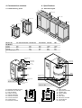
El humidificador de vapor de la serie SD es del tipo de
electrodos sumergidos y está avalado por la más
avanzada tecnología microprocesada.
The SD series steam humidifier is of the immersed electrode type and is based on the most advanced microprocessor technology.
El humidificador está compuesto por un mueble que
contiene:
- una parte hidráulica de producción de vapor completa
con electroválvulas para el llenado/vaciado de agua;
- el cuadro eléctrico;
- el control electrónico.
The humidifier frame consists of:
- a steam production hydraulic unit comprising solenoid
valves for the fill/drain water;
- the switchboard;
- the electronic controller.
1.1 Características principales
1.1 Main characteristics
Funcionamiento: completamente automático, es gestionado por el control que lleva integrado el sistema antiespuma. Gestionando el nivel de agua en el interior del
cilindro de producción se regula la producción de vapor
en base a las necesidades del ambiente.
Operation: completely automatic, it is managed by the
control containing the patented anti-foaming system.
Through the control of water level within the production
cylinder, it is possible to modulate the steam production
according to the ambient.
Adaptable: puede ser instalado en cualquier area geográfica gracias a su capacidad de adaptación a las características físico/químicas del agua de red.
Adaptability: it can be installed in any geographical area
due to its adaptation capability to the chemical and physical
characteristics of the waterworks water.
Prestaciones: el cilindro de producción de vapor produce
vapor estéril eliminando el 99,8% de las impurezas del
agua.
Performance: The steam production cylinder produces
sterile vapour holding back 99.8% of the impurities contained
in the water.
Sistema anti espuma AFS: el algoritmo de gestión
inteligente ‘AFS anti foaming system’, resumido, individua
y elimina la espuma en los cilindros gracias a un particular ciclo de trabajo.
Anti-foaming system AFS: the patented “AFS anti-foaming
system”, detects and eliminates the foam in the cylinders
by means of a particular work cycle.
Mantenimiento: la geometría de los electrodos ‘box-type’
unida al nuevo algoritmo de gestión ’AFS’ garantiza bajos
costos de mantenimiento ordinario gracias a una mayor
duración de los cilindros.
Maintenance: The geometry of the “box-type” electrodes
together with the new “AFS” management algorithm ensures
low ordinary maintenance costs because of a longer life
of the cylinders.
Homologaciones: la calidad y seguridad de los humidificadores está garantizada por el sistema de diseño y producción certificado ISO 9001, disponiendo del marchamo
CE y de las homologaciones alemana TÜV y americana
UL.
Approvals: humidifier quality and safety are assured by the
ISO 9001 design and production certificate as well as by
the CE labelling, the German TÜV and the American UL
homologations.
Conexionado serial: todos los humidificadores SD están
predispuestos para el conexionado en red para la realización de un sistema de supervisión y/o teleasistencia o
para la integración en BMS.
Serial connection: all the SD humidifiers can be connected to the network in order to create supervisory and telemaintenance systems or for the BMS integration.
Aplicaciones: son múltiples: acondicionamiento de oficinas, zonas de trabajo y habitaciones privadas, refrigeración, salas blancas, zonas de producción y salas de ordenadores.
Applications: there are many: office conditioning, working
places and private houses, refrigeration, clean rooms, production areas and computer room air-conditioner centres.
Gama: están disponibles 14 modelos con 5 tipos de control diferente: del más pequeño capaz de producir 1kg/h
de vapor, al más grande de 126 kg/h.
Range: 14 models are available, with 5 different controls,
that allow a steam production ranging from 1kg/h to 126kg/h.
1
2. Representación de la instalación
2. Humidifier system configuration
2.1 Ejemplo de instalación de un humidificador SD
2.1 Installation example of a SD humidifier
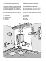
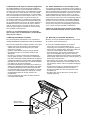
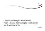
A continuación son representadas gráficamente, de forma
muy esquemática, las diferentes partes que componen
una instalación de humidificación Carel. Esto es para facillitar al cliente la compra y la realización de una instalación
completa con todos sus componentes.
Here below the various components of a Carel humidification plant are diagrammatically shown. The aim is to help
the customer when purchasing and carrying out a plant
with all its components.
En las páginas sucesivas trataremos de modo detallado el
montaje de la instalación para aplicación en conducto o
ambiente.
In the next pages, the plant installation for duct or ambient
application will be discussed in detail.
1.
2.
3.
4.
5.
6.
1.
2.
3.
4.
5.
6.
Sonda humedad
Alimentación eléctrica
Distribuidor líneal
Distribuidor ventilado
Llenado agua
Vaciado agua
Humidity probe
Power supply
Linear steam distributor
Ventilated steam distributor
Fill water
Drain water
3
1
4
5
2
6
2
3. Cálculo de una instalación con humidificadores SD
3. Plant design of a SD humidifier
3.1 Dimensionado de una instalación y selección del humidificador
3.1 Dimensioning of a plant and choice of the
humidifier
Para poder valorar el modelo de humidificador adecuado
a la aplicación que se desea realizar, es necesario valorar
el caudal necesario de vapor requerido por el ambiente,
teniendo presente una serie de factores indicados a continuación.
In order to correctly evaluate the humidifier model that is
suitable for the application to be realized, it is necessary
to establish the steam flow rate being required from the
ambient, bearing in mind a number of factors which will be
described below.
3.2 Valoración del caudal de vapor
3.2 Evaluation of the steam flow rate
Para calcular la necesidad de un ambiente a humidificar
se deben tener en cuenta los siguientes factores:
- volumen del local (m3);
- condiciones actuales del local [temperatura (°C) y
humedad (%H.R.);
- condiciones deseadas en el local [temperatura (°C) y
humedad relativa (%H.R.);
- características de los materiales presentes en el interior
(cantidad, factor higroscópico, número de personas);
- tiempo deseado para la puesta a régimen;
- eventuales inmisiones de aire exterior (infiltraciones,
apertura ocasional de puertas y ventanas);
- cantidad de aire exterior de renovación (m3/h);
- condiciones externas de proyecto [temperatura (°C) y
humedad relativa (%H.R.);
- condensación sobre la batería de frío.
To calculate the requirements of an ambient to be humidified the following factors must be taken into account:
- volume of the room (m3);
- actual conditions of the room {temperature (°C) and
relative humidity (%rh)};
- wanted conditions in the room {temperature (°C) and
relative humidity (%rh)};
- characteristics of the materials occurring inside
(quantity, hygroscopic factor, number of persons);
- time needed to reach full efficiency;
- possible intake of external air (infiltrations, occasional
opening of doors and windows);
- amount of external air change (m3/h);
- external design conditions {temperature (°C) and
relative humidity (%rh)};
- condensation on the cold battery coil.
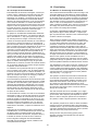
Gracias al diagrama psicrométrico podemos obtener ∆x
(humedad absoluta g/kg) deseada en el ambiente a
humidificar y todos los datos necesarios para el correcto
dimensionado.
Through the use of a psychometric diagram it is possible
to obtain the ∆x (absolute humidity g/kg) required by the
ambient as a completion of all data that are needed for
the correct dimensioning.
Así con la siguiente fórmula se consigue el caudal de
vapor necesario de vapor en kg/h:
Finally, the following formula allows to calculate the steam
rate being required in kg/h:
Q = V x 1,2 x (x2-x1) / 1.000 = kg/h + Y
Q = V x 1.2 x (x2-x1) / 1,000 = kg/h + Y
donde:
Q= cantidad de vapor necesario en el ambiente en kg/h
(asumiendo el peso específico a 4°C igual a 1 kg/m3, los
kg/h corresponden a l/h);
V= volumen de aire(*);
1,2= peso específico del aire kg/m3 (condiciones de 21°C
y 1013 mbar);
x1= humedad absoluta del aire a humidificar g/kg;
x2= humedad absoluta deseada en el ambiente g/kg;
Y= parámetro que tiene en cuenta los valores anteriormente nombrados no contemplados en la fórmula pero a
considerarse en base al tipo de aplicación.
where:
Q= amount of steam required in ambient kg/h (if the specific
gravity at 4°C is 1kg/m3, the kg/h correspond to the l/h);
V= air volume (*);
1,2= specific gravity of the air kg/m3 (conditions of 21°C
and 1013mbar);
x1= absolute humidity of the air to be humidified g/kg;
x2= absolute humidity needed in ambient g/kg;
Y= parameter that takes into account the above mentioned
values which are not reported in the formula but to be
considered according to the type of application.
(*) For ambients with recirculation air only: V = m3 of the
room (see note).
For ambients with external air change: V= external air
volume per hour introduced into the ambient (m3/h)
(*) Para ambientes sólo con aire de recirculación: V = m3
del local (ver nota).
Para ambientes con aire exterior de renovación: V= volumen horario de aire exterior introducido en el ambiente
(m3/h).
Note: since it does not process change air, when the relative humidity value of choice is reached, the humidification plant will work very little in order to keep constant the humidity degree. Therefore, it is important to
examine the necessity to reach full efficiency within
more or less long periods of time in order to optimize
the costs in case of request of considerable power.
Nota: no tratando el aire de renovación, una vez conseguido el valor de humedad requerido, la instalación
de humidificación trabajará muy poco sólo para mantener constante el grado de humedad. Es importante
también, a fin de optimizar los costes cuando se trata
de grandes potencias, verificar la necesidad de llegar
a régimen en un tiempo más o menos largo.
3
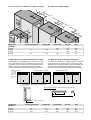
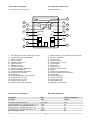
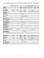
4. Specifications
4. Características técnicas
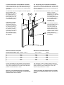
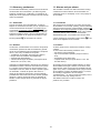
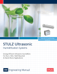
4.1 Size and weights
4.1 Dimensiones y pesos
B
SD 323 - 342
SD 360 - 384
B
SD 106 - 313
C
SD 3B3
SD 101 - 305
B
C
A
C
A
A
A
A
Modelo SD
SD Models
101-102-103-303-305 106-308-313
323-333-342
360-384
3B3
A (mm)
B (mm)
C (mm)
Peso/Weight (kg/h)
330
203
570
16.5
620
355
860
49
1020
355
860
84.5
1420
355
860
116
360
222
640
19.8
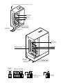
bandeja de carga
fill tank
conductímetro
conductimeter
conductimetro
conductimeter
solo / only
SD101 - 305
conductímetro
conductimeter
cilindro
cylinder
cilindro
cylinder
válvula de vaciado
fill valve
bomba de vaciado
drain pump
válvula de llenado
fill valve
SD 101 - 313
válvula de vaciado
drain valve
SD 323 - 3B3
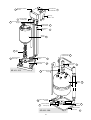
V.
E.
T.
B.
C.
S.
R.
D.
P.
Depósito de llenado de agua
Electrodos de nivel alto
Tubo de rebose
Cilindro de vapor
Válvula de llenado
Válvula de vaciado
Control electrónico
Conductímetro
Bomba de vaciado
V
E
D
E
T
R
D
B
R
B
T
C
S
C
SD101 - 313
SD323 - 3B3
4
P
S
V.
E.
T.
B.
C.
S.
R.
D.
P.
Water fill tank
High level electrodes
Overflow pipe
Steam cylinder
Fill valve
Drain valve
Electronic controller
Conductimeter
Drain pump
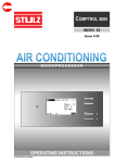
4.2 Position of steam outlets
4.2 Posición de las salidas de los tubos de vapor
A
B
C
D
A
B
C
D
B
A
B
D
Modelo SD
SD Model
D
101-102-103-303-305
A (mm)
B (mm)
C (mm)
D (mm)
106-308-313
323-333-342
360-384
3B3
81
105
80
170
95
110
145
80
170
310
145
80
170
310
145
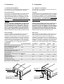
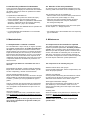
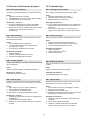
4.3 Montaje en pared del humidificador de vapor
4.3 Wall mounting of the steam humidifier
Comprendido con el humidificador se suministra una guía
tipo ‘L’ para fijarla en la pared mediante tornillos. Una vez
montada la guía en la pared colgar el humidificador, fijándolo con los tornillos de bloqueo situados en la parte
posterior interna de la parte hidráulica (ver figura inferior).
As a kit of the humidifier an “L” shaped bracket is supplied
to be attached to the wall by means of screws. Once the
bracket has been mounted on the wall, hang the humidifier and
secure it with the fixing screws that is placed in the internal
back-piece of the hydraulic part below (see figure below).
Modelos / Models
101 102
103 106
303 305
308 313
323 333
342
Modelos / Models 360-384
,,
Modelos / Models
3B3
soporte posterior / Bracket to be mounted on wall
soporte para fijar a la pared / Bracket to be mounted on the wall
A
B
C
tornillo de fijación / Fixing screw
Modelo SD
SD Model
A (mm)
B (mm)
C (mm)
101-102-103-303-305
106-308-313
323-333-342
360-384
3B3
50
110
210
50
110
210
65
150
430
105
150
810
70
150
1190
5
5. Conexiones
5. Connections
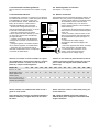
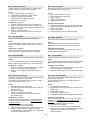
5.1 Conexionado hidráulico
5.1 Hydraulic connections
La instalación de un humidificador precisa de la conexión
de la acometida de agua de alimentación y desagüe.
The installation of a humidifier involves the connection to
the water mains and drainage.
Tubo de alimentación
En el tubo que aporta el agua debe ser colocada una válvula de paso de un diámetro interno mínimo de 6 mm.
Para simplificar la operación de instalación se aconseja
utilizar el tubo flexible Carel cod. 1312350APN y el racor
rápido girable de 3/4”G a 180° cod. 9995727ACA o 90°
cod. 9995728ACA. La presión de red debe estar comprendida entre 1 y 10 bar y la temperatura no debe superar
los 50°C.
Fill piping
The water piping has to be bypassed through an interception
tap and must have a minimum diameter of 6mm. To simplify
the operation of installation, use the Carel flexible piping
code 1312350APN and the 180° 3/4”G fast swivel fitting
code 9995727ACA or 90° code 9995728ACA. Water pressure
must range between 1 and 10bars and temperature must
not exceed 50°C.
Atención: alimentar el humidificador con agua de red.
No utilizar agua desmineralizada. El agua debe tener
una conductividad de 125 a 1250 µS/cm y dureza de
15 a 30°F. En lo que se refiere al uso de descalcificadores o sistemas de tratamiento de aguas particularmente duras, la dureza final no deberá ser inferior al
40% de la dureza inicial y por tanto no inferior a 15°F.
Caution: fill the humidifier with water network. Do not
use demineralized water. Water conductivity must
range between 125 and 1250µS/cm and total hardness
between 15 and 30°F. As regards the use of softeners
or treatment systems of unusually hard waters, the
final hardness will not be less than 40% of the initial
hardness and in any case not less than 15°F.
Tubo de desagüe.
El agua desagüada por el humidificador no es tóxica ni
corrosiva y puede ser drenada sobre el sistema de
desagüe de las aguas blancas. Para la primera parte del
desagüe es necesario utilizar tubo de goma o plástico no
conductivo para impedir fugas de corriente hacia el tierra.
Sucesivamente se aconseja realizar un sifón para evitar
olores en el ambiente. Carel dispone un tubo de desagüe
en goma flexible Ø40 cod. 1312357APG y Ø30 cod.
1312356APG.
Drain piping
Water draining from the humidifier is neither toxic nor corrosive and may therefore drained into the system of the
storm sewage. For the first part of the drainage it is
necessary to use rubber and/or non conductive plastic to
prevent current leakages to the ground. Subsequently, the
installation of a siphon is suggested so as to avoid odours
in ambient. Carel offers a Ø40 flexible rubber piping for
drainage code 1312357APG and Ø30 code 1312356APG.
Modelo SD
101-102-103-303-305
Caudal max agua de alimentación l/min 1,2
Max. instantaneous flow rate l/min
Rosca de alimentación agua
3/4G
Fill water connection
Caudal max agua de alimentación l/min 1,6
Max. instantaneous flow rate of
drain water l/min
Rosca agua del desague/Drain water connection
Filetto/Thread
3/4G
Porta goma (mm)
Rubber pipe fitting (mm)
30
106-308-313
2,5
323-333-342
10
360-384
20
3B3
30
3/4G
3/4G
3/4G
3/4G
1,6
10
20
30
3/4G
1-1/4G
1-1/4G
1-1/4G
30
40
40
40
20
40
40
40
Diametro min. tubo
de condensación (mm)
Min. diameter of drain piping (mm)
20
alimentación elèctrica
power supply
alimentación elèctrica
power supply
señales externas
external signal
señales externas
external signal
vaciado
drain
SD 101 - 313
vaciado
drain
llenado
fill
SD 323 - 3B3
6
llenado
fill
5.2 Conexionado sondas/reguladores
5.2 Probe/regulator connections
Para los diversos conexionados ver el capítulo 7.4 (pág.
24).
See chapter 7.4 on page 24.
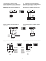
5.3 Conexionado eléctrico
5.3 Electric connection
El humidificador necesita una conexión a la red eléctrica.
The humidifier must be connected to the electric network. It is
Es suficiente llevar el neutro y la/las fases para alimentar
sufficient to carry the ground, the phase/phases and the
el humidificador en todas sus partes (conneutral (if single phase) to completely supply
trol, electroválvulas, bomba, distribuidor venthe humidifier (control, solenoid valves,
MOD.
SD 305
tilado). Si se realiza un cuadro eléctrico
pumps, ventilating unit). If an electronic
A
5,5
V~
380
antes del humidificador será necesario:
panel
is placed upstream to the humidifier it
Hz
50 60
PH
3
- dimensionar el magnetotérmico para un
will be necessary:
kW
3,6
kg /h
5
valor de intensidad igual al menos 1,5 veces
- to dimension the electromagnetic switch at
IP
32
la corriente nominal de la máquina;
least once and a half the nominal absorption
02/09/96
DATE PROD
SD 305H0380
CODE
- antes de la conexión leer los valores
of the unit;
sobre la etiqueta de datos situada en el inte- before connection, read the values on the
rior del cuadro eléctrico del humidificador
label of the registration data situated within
SERIAL N°
(ver figura al lado);
the humidifier electric panel (see figure on
- controlar que la tensión de alimentación
the left);
corresponda a la tensión nominal del humi- to check that the voltage supply
MADE IN ITALY
dificador;
corresponds to the nominal voltage of the
- proteger el aparato con fusibles respetanhumidifier;
do los valores sugeridos en la tabla inferior;
- protect the apparatus with fuses, according
Via dell’Industria 11
35020 Brugine - (Pd) - Italy
- asegurarse que el conexionado del prito the values listed in the table below;
Tel. (+39) 049.971.66.11
Fax (+39) 049.971.66.00
mario del transformador interno corresponda
- to check that the connections to the
a la tensión de alimentación.
primary of the internal transformer
correspond to the voltage supply.
Caution: do not remote the panel-mounted control at
a distance exceeding 4 metres avoiding to pass near
power cables and magnetic fields (utilize unifilar
cables only).
Atención: no remotar el control montado en el panel
del humidificador a una distancia superior a 4 metros,
prestando atención a no pasar cerca de cables de
potencia y campos electromagnéticos.
Modelo SD
101
Sección de cable
2.5
alimentación (mm2)
Power cable cross
section (mm2)
Potencia del fusible (A) 6
Fuse current-carrying
capacity (A) (fast type)
102
103
106
303
305
308
313
323
333
342
360
384
3B3
2.5
2.5
6
2.5
2.5
2.5
4
10
16
25
35
70
95
10
16
32
6
8
12
20
40
50
63
100
125
200
Valores referidos a la instalación del cable en PVC o
goma en canal cerrado
Values referred to a PVC or rubber cable placing in a
closed cable duct.
Nota: válidos para tensiones monofásicas 220/240 V o
trifásicas 380/415 V y longitud máxima de los cables
50 metros.
N.B.: validity for 220/240V single-phase voltages or
380/415V three phase voltage and a maximum cable
length of 50 metres.
7
alimentación distribuidor ventilado / ventilated power supply
magnetotérmico
power contactor
trasformador
transformer
fusible / fuses
señal externa
external signal
SD 101 - 313
alimentación eléctrica
power supply
magnetotérmico
power contactor
fusible / fuses
alimentación distribuidor ventilado
ventilated power supply
trasformador
transformer
señal externa
external signal
SD 323 - 3B3
alimentación eléctrica
power supply
paro/marcha
remoto
remote on/off
20 21
entrado señal relé alarma
signal inputs alarm relay
56 57 58 59 60 70 71 72
línea
línea
PE L3 L2 L1 SD 303, 305
308,313, 323, 333, 342
360, 384, 3B3
8
PE N
L
SD 101, 102
103, 106
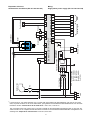
Alimentación monofásica (SD 101-102-103-106)
Single-phase power supply (SD 101-102-103-106)
Alarm
External signal
Remote On/Off
20 21
C = 220 - 240V~
D = 380 - 415V~
E = 440 - 480V~
F = 575V~
Line
K
N L PE
voltage
*** = BPrimary
= 200 - 208V~
***
0V
F3 1A ATM/gG
F1 1A ATM/gG
0V
F4 2A GT
24V
230V
F2 1A ATM/gG
Mounted on
Transformer 100VA transformer
ON/OFF
56 57 58 59 60 70 71 72
68 69
N0
+12 S1
G0
G
Control CDC / P / H / D / T
67 66
61 62
54 55
Drain valve
K
X2
X1
S2 GND -12
52 53
65 63 64
Fill valve
,,
,,
Boiler
TAM
Optional fan
C
50 51
Conductimeter
Level sensor
56 57 58 59 60 70 71 72
Wiring
NC
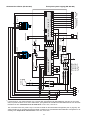
Esquemas eléctricos
* Los bornes 66-67, solo están presentes con el control CDD, para gestionar la dehumidificación (ver pág. 20). El control
CDD, se puede combinar con el control “Macrobase”, para gestionar la humidificación/dehumidificación de una central de
tratamiento de aire. Características de la salida 66-67: I max 5 mA, V max 30 V~
The connections 66-67 are present only on the CDD controller for the dehumidifier management (see on page 20). The
CDD controller can be compled with the Macrobase controller for the humidification/dehumidification management of air
handling units. Output 66-67 characteristics: Imax 5mA; Vmax 30V~
9
Remote On/Off
External signal
Alarm
56 57 58 59 60 70 71 72
20 21
C = 220 - 240V~
D = 380 - 415V~
E = 440 - 480V~
F = 575V~
Line
K
L1 L2 L3 PE
voltage
*** = BPrimary
= 200 - 208V~
***
0V
F3 1A ATM/gG
F1 1A ATM/gG
0V
F4 2A GT
24V
230V
F2 1A ATM/gG
Mounted on
Transformer 100VA transformer
ON/OFF
56 57 58 59 60 70 71 72
68 69
N0
+12 S1
G0
G
Control CDC / P / H / D / T
61 62
54 55
67 66
Drain valve
K
X2
X1
S2 GND -12
52 53
65 63 64
Fill valve
,,
Boiler
TAM
Optional fan
C
50 51
Conductimeter
Level sensor
NC
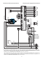
Three-phase power supply (SD 303-305-308-313)
Alimentación trifásica (SD 303-305-308-313)
* Los bornes 66-67, solo están presentes con el control CDD, para gestionar la dehumidificación (ver pág. 20). El control
CDD, se puede combinar con el control “Macrobase”, para gestionar la humidificación/dehumidificación de una central de
tratamiento de aire. Características de la salida 66-67: I max 5 mA, V max 30 V~
The connections 66-67 are present only on the CDD controller for the dehumidifier management (see on page 20). The
CDD controller can be compled with the Macrobase controller for the humidification/dehumidification management of air
handling units. Output 66-67 characteristics: Imax 5mA; Vmax 30V~
10
Alarm
External signal
Remote On/Off
20 21
C = 220 - 240V~
D = 380 - 415V~
E = 440 - 480V~
F = 575V~
Line
K
L1 L2 L3 PE
voltage
*** = BPrimary
= 200 - 208V~
***
0V
F3 2A ATM/gG
F1 2A ATM/gG
0V
F4 4A GT
24V
230V
F2 2A ATM/gG
Transformer 250 VA
Mounted on
transformer ON/OFF
NC
C
N0
S2 GND -12
+12 S1
G0
G
Control CDC / P / H / D / T
67 66
54 55
61 62
RK
K
RC
X1
X2
Drain pump
56 57 58 59 60 70 71 72
52 53
65 63 64
Fill valve
RD
TAM
Optional fan
68 69
50 51
Conductimeter
,,
,,
Boiler
Level sensor
56 57 58 59 60 70 71 72
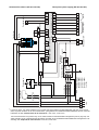
Three-phase power supply (SD 323-333-342)
Alimentación trifásica (SD 323-333-342)
* Los bornes 66-67, solo están presentes con el control CDD, para gestionar la dehumidificación (ver pág. 20). El control
CDD, se puede combinar con el control “Macrobase”, para gestionar la humidificación/dehumidificación de una central de
tratamiento de aire. Características de la salida 66-67: I max 5 mA, V max 30 V~
The connections 66-67 are present only on the CDD controller for the dehumidifier management (see on page 20). The
CDD controller can be compled with the Macrobase controller for the humidification/dehumidification management of air
handling units. Output 66-67 characteristics: Imax 5mA; Vmax 30V~
11
Remote On/Off
External signal
Alarm
56 57 58 59 60 70 71 72
20 21
ON/OFF
C = 220 - 240V~
D = 380 - 415V~
E = 440 - 480V~
F = 575V~
voltage
*** = BPrimary
= 200 - 208V~
***
0V
F3 4A ATM/gG
F1 4A ATM/gG
0V
F4 4A GT
24V
230V
F2 2A ATM/gG
Mounted on
transformer
K2
K1
Line
K2
K1
L1 L2 L3 PE
K1 K2 K1 K2
8A 7A 6A 5A 4A 3A
TAM 2
TAM 1
Transformer 400 VA
C
N0
S2 GND -12
+12 S1
G0
G
68 69 61 62 56 57 58 59 60 70 71 72
Control CDC / P / H / D / T
64
55
67 66
52 53
4B 3B 2B
Drain pump 1
Drain pump 2
X2
X1
Optional fan
Drain
Fill valve 2
9C 8C 7C Drain 12A 65
Fill
64
Fill 11A
Board 98C153C005
10A
GND 10A
9A
I sig 9A
1B 1C 2C 4C 3C
13A 5C 1A 6C 2A
65
Fill valve 1
Conduct imeter
,, ,,
Boiler 1
Boiler 2
54
50 51
NC
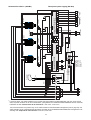
Three-phase power supply (SD 360-384)
Alimentación trifásica (SD 360-384)
* Los bornes 66-67, solo están presentes con el control CDD, para gestionar la dehumidificación (ver pág. 20). El control
CDD, se puede combinar con el control “Macrobase”, para gestionar la humidificación/dehumidificación de una central de
tratamiento de aire. Características de la salida 66-67: I max 5 mA, V max 30 V~
The connections 66-67 are present only on the CDD controller for the dehumidifier management (see on page 20). The
CDD controller can be compled with the Macrobase controller for the humidification/dehumidification management of air
handling units. Output 66-67 characteristics: Imax 5mA; Vmax 30V~
12
13
K1
Line
L1 L2 L3 PE
K2
K3
X2
K3
C = 220 - 240V~
D = 380 - 415V~
E = 440 - 480V~
F = 575V~
voltage
*** = BPrimary
= 200 - 208V~
0V
24V
ON/OFF
F4 2A GT
F5 4A GT
67 66
Drain pump 1
Fill valve 1
Boiler 1
G0
+12 S1
S2 GND -12
N0
C
NC
50 51
20 21
External signal
Alarm
56 57 58 59 60 70 71 72
68 69 61 62 56 57 58 59 60 70 71 72
G
Control CDC / P / H / D / T
52 53
Remote On/Off
Mounted on transformer
74
54
55
64
65
Drain pump 2
Fill valve 2
4B 3B 2B 9C 8C 7C Drain 12A 65
Drain
Fill
64
Fill 11A
10A
GND 10A
9A
I sig 9A
13A 5C 1A 6C 2A
Transformer 630 VA
***
0V
K2
F3 4A ATM/gG
F1 4A ATM/gG
K1
1C 2C 4C 3C
230V
1B
Board 98C153C005
8A 7A 6A 5A 4A 3A
Drain pump 3
Fill valve 3
Conductimeter
Boiler 2
,
,,
,,
,,,,,
F2 2A ATM/gG
K1 K2 K3 K1 K2 K3
TAM 3
TAM 2
TAM 1
X1
Optional fan
Boiler 3
Alimentación trifásica (SD 3B3)
Three-phase power supply (SD 3B3)
* Los bornes 66-67, solo están presentes con el control CDD, para gestionar la dehumidificación (ver pág. 20). El control
CDD, se puede combinar con el control “Macrobase”, para gestionar la humidificación/dehumidificación de una central de
tratamiento de aire. Características de la salida 66-67: I max 5 mA, V max 30 V~
The connections 66-67 are present only on the CDD controller for the dehumidifier management (see on page 20). The
CDD controller can be compled with the Macrobase controller for the humidification/dehumidification management of air
handling units. Output 66-67 characteristics: Imax 5mA; Vmax 30V~
6. Distribución del vapor
6. Steam distribution
La selección del distribuidor de vapor debe ser realizada
en función del lugar en el cual se desea montar. Si el
vapor debe ser distribuido en ambiente puede preverse el
posicionamiento del distribuidor ventilado. Si el vapor
debe ser distribuido mediante conductos o en centrales
de tratamiento de aire, es necesario prever el uso de
distribuidores lineales.
It is recommended to chose the type of steam distributor
according to the place where steam is introduced. If the
steam must be distributed into an ambient it is necessary
to provide for ventilated steam distributors. If on the contrary
the steam has to be introduced into a piping or into air
handling units, it is necessary to use linear distributors.
Caution: the steam pipe length, between the humidifier and the distributor, must not exceed 4 metres.
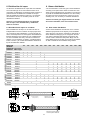
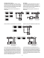
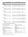
6.1 Distribución del vapor en conducto
6.1 Duct steam distribution
Para la distribución del vapor en conductos de aire es
indispensable el uso de un difusor de vapor proporcionado a la potencia del humidificador y a la sección del conducto. Carel dispone de una vasta gama de distribuidores
lineales divididos en dos categorias: una completamente
en acero inoxidable AISI 304 y otra más económica en
aluminio con los extremos en plástico. La tabla siguiente
indica el número y el modelo de distribuidor adecuado al
tipo de humidificador utilizado.
Air-duct steam distribution involves the use of a steam
distributor proportional to the capacity of the humidifier
and to the duct cross section. Carel has a wide range of
linear distributors belonging to two categories: the first
one made of stainless steel (all the components), the
second made of aluminium with plastic flange. The following table shows the number and model of the distributor that is suitable for the humidifier being utilized.
Modelo SD
101
SD Model
Distribuidor Long. max.
Distributor Max. lenght
102
103
SDP03S
SDP04S
SDP06S
SDP08S
SDP10S
SDP05L
SDP06L
SDP08L
SDP10L
SDP12L
SDP16L
SDP20L
SDP30E
SDP45E
SDP65E
SDP85E
SDP120E
OEM12
OEM22
1
1
1
1
1
1
250mm
350mm
550mm
750mm
950mm
450mm
550mm
750mm
950mm
1150mm
1600mm
2000mm
300mm
450mm
650mm
850mm
1200mm
1
1
1
106
1
1
1
1
1
1
1
1
1
1
1
1
1
1
1
1
1
1
1
100
70
305
308
323
333
342
360
384
3B3
1
1
1
1
1
1
2
2
2
2
2
2
2
2
2
2
2
2
2
2
2
2
2
2
4
4
4
4
4
4
4
4
4
4
4
4
6
6
6
6
6
6
2
2
2
2
2
2
2
2
2
4
4
4
4
4
4
6
6
6
1
1
1
1
1
1
1
1
1
1
1
1
1
313
1
1
1
1
1
1
1
1
1
1
1
1
1
1
1
1
1
15
303
1
1
1
1
1
15
X : Ø22 (model S)
Ø30 (model L)
Ø6
distribuidor acero inox
stainless steel distributor
Y : Ø12 / Ø22
35
35
Ø22
63
85
Ø30
63
Ø58
Y
Ø22
Ø30
X
74
120
25
58
21
oem
al./plast.
acero inox - stainless steel
Atención: se recomienda mantener la longitud del
tubo de vapor, entre humidificador y distribuidor,
sobre los 4 metros.
Ø5
distribuidor aluminio/plástico
aluminium/plastic distributor
14
distribuidor OEM
OEM distributor
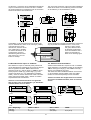
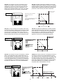
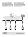
The choice and positioning of the linear steam distributors
inside the air ducts or air-conditioning units are essential
for the efficiency of the humidification system.
La selección y la posición de los distribuidores lineales de
vapor en el interior de los conductos de aire o unidades
de acondicionamiento es fundamental a fin de una buena
eficiencia del sistema de humidificación.
≥500
H > 250
H > 500
0,4H 0,4H
0,7 H
H > 350
0,25H 0,25H 0,35H
≥500
≥70
H min=200
≥500
H min=200
H > 300
H > 500
H > 500
300 < H < 500
=
=
=
0,5 H
=
=
Compatibles con las dimensiones de los conductos de
aire, los distribuidores, deben ser lo más largos posible y
colocarlos lejos de curvas,
derivaciones, cambios de sección, rejillas, filtros, ventiladores. Para la eliminación de la
condensación, montar el
distribuidor ligeramente inclinado (2/3%) tal y como se
indica en el dibujo.
0,3 H
0,3 H
=
=
0,3 H
0,3 H
=
Air-duct dimensions permitting the distributors must be as
long as possible and installed far from: curves, forks,
changes in piping section
size, grids, filters and fans.
To eliminate condensation,
mount the distributor with a
slight 2/3% inclination as
shown in the following figure.
÷ 2/3%
6.2 Distribución del vapor en ambiente
6.2 Ambient steam distribution
Para distribuir el vapor en ambiente puede preveerse el
uso de distribuidores ventilados de los cuales hay disponibles los siguientes modelos: VSD en dimensiones
pequeña “small” (S) y grande “large” (L), VRD en dimensiones pequeña “small” (S), grande “large” (L) y extra
grande “extra large” (XL). Los distribuidores ventilados
VSDS y VSDL se montan directamente sobre el humidificador, mientras los VRDS, VRDL y VRDXL se instalan
separadamente del humidificador.
Ambient steam distribution requires the use of ventilated
steam distributors. The available models are the following:
VSD in small (S) and large (L) sizes, VRD in small (S),
large (L) and extralarge (XL) sizes.
The VSDS and VSDL ventilated distributor are mounted
on the humidifier, whereas VRDS, VRDL and VRDXL
models are mounted separately from the humidifier.
Caution: the steam duct length, between the humidifier and the ventilated distributor, must not exceed 4
metres.
330
263
110
110
Atención: se recomienda mantener la longitud del
tubo de vapor, entre el humidificador y el distribuidor
ventilado, dentro de los 4 metros.
192
360
VSDS
206
VSDL
692
150
150
VRDXL
360
330
206
192
VRDS
VRDL
Peso / Weight (kg)
VSDS-S / VRD-S
VSD-L / VRD-L
VRDXL
VSD (kg)
VRD (kg)
3
3,1 (3.1)
3,5 (3.5)
3,65 (3.65)
22,5 (22.5)
15
355
6.3 Distribución del vapor en cámaras frigoríficas
6.3 Steam distribution in cold storage rooms
Es posible humidificar una cámara frigorífica utilizando
para la distribución del vapor el distribuidor ventilado. Es
necesario sólo prestar atención que el distribuidor ventilado, compuesto de un motor eléctrico a 230 Vac, trabaje
dentro de los límites de funcionamiento. La cámara debe
tener una temperatura de funcionamiento entre -10÷+60°C
y la humedad relativa hasta un máximo de 80% H.R.
La cámara no debe tener un ambiente de condensación.
En el caso de que no pudieran ser respetados estos límites es posible distribuir el vapor en la cámara mediante el
distribuidor líneal. En ambos casos el vapor no deberá
entar en contacto directo con el flujo de aire frío proveniente del grupo frigorífico presente en la cámara, para
evitar posibles condensaciones.
It is possible to humidify a cold storage room by means of
a ventilated steam distributor. However it must be remembered
that the ventilated steam distributor has a 220Vac electric
motor that involves ambient limits of operation. The room
working temperature must have a range of -10÷+60°C
while its relative humidity value must not exceed 80%rH.
In any case, the room must not be a condensing ambient.
If these limits are not respected, it is possible to distribute
the steam in the room by means of the linear distributor.
In both cases the steam must not be exposed to direct
cold air flow coming from the refrigerating system of the
room, in order to prevent possible condensations.
Caution: the steam duct length, between the humidifier
and the ventilated distributor, must not exceed 4 metres.
Atención: se recomienda mantener la longitud del
tubo de vapor, entre el humidificador y el distribuidor,
dentro de los 4 metros.
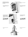
6.4 Montaje distribuidor ventilado
6.4 Mounting of ventilated distributors
En la figura siguiente está ilustrado como se realiza el
montaje del distribuidor ventilado VSD sobre el humidificador.
Mounting of the VSD ventilated distributor on the humidifier is shown in the following figure:
Para montar el distribuidor ventilado proceder como sigue:
• quitar la tapa de la parte superior del humidificador
soltando las cuatro tuercas de fijación por la parte
interior de la máquina;
• quitar los cuatro tapones de goma, donde deberán
introducirse las guias y los tornillos de fijación del
distribuidor;
• introducir por el orificio superior del humidificador el
tubo de salida del vapor y el tubo de la condensación.
Éste último debe llegar hasta la bandeja de recogida de
condensados situada en la parte inferior del humidificador
(bandeja de fondo) donde el agua es drenada mediante
una abertura en el grupo de desagüe;
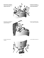
• tras haber introducido los dos pivotes de la unidad ventilada en sus respectivos agujeros, el bloqueo de la unidad
se realizará mediante los dos tornillos autoroscantes;
• el conexionado eléctrico se realiza mediante un conector
macho de la unidad ventilada que debe pasar a través
del pasacables situado en la parte superior del
humidificador;
• el tubo de salida del vapor debe ser fijado al cilindro
con la brida suministrada.
To mount the ventilated distributor do as follows:
• remove the cover from the humidifier top by
unscrewing the four fastening nuts inside the machine;
• remove the four adhesive plugs, where the guides and
fixing pins of the distributor will be inserted;
• insert the fill steam pipe and the condensation drain
pipe. The condensation drain pipe must reach the
collecting tank being found at the bottom of the humidifier
(bottom tank) where water, through a special opening, is
drained into the drain device;
• after inserting the four pins of the ventilating unit into
their respective slotted holes of the humidifier, the unit
may be fixed by means of the two supplied self-tapping
screws;
• the electrical connection is obtained through a male
connector of the ventilating unit that must be pass
through the suitable core hitch to be pierced on the
humidifier tops;
• the steam pipe must be fixed to the cylinder with a
supplied spring clip.
tapa da sacar
cover to remove
16
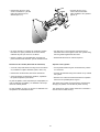
6.5 Posicionamiento del distribuidor ventilado
6.5 Positioning of the ventilated distributors
El pleno funcionamiento del humidificador, depende de la
correcta distribución del vapor, debe realizarse homogeneamente, sin proyeccion de gotas y sin condensaciones
apreciables.
The complete and proper operation of the humidifier, that
depends on the correct steam distribution, must be homogeneous, without droplet projections and avoiding significant condensations.
,
,
,
,
,
The recommended minimum distances, shown in the table
below, for a proper
positioning of the steam
D
distribution unit, refer both
to the models to be
mounted separately from
the humidifier (VRD) and
to the models directly
mounted on the
humidifier (VSD).
Las distancias mínimas aconsejadas en la tabla siguiente
para la instalación del
distribuidor, se refieren a
A
B C
los modelos para montaje separado del humidificador (VRD) como los
de montaje directo sobre
el humidificador (VSD).
El distribuidor ventilado
debe ser instalado en
una posición tal que el
flujo de aire humidificado
no colisione contra personas, luminarias, aparatos eléctricos, techos y
superficies frias antes de
que el vapor sea totalmente absorbido (generalmente sobre 2 metros
de distancia).
E
F
The ventilated distributor
must be installed so as to
avoid that the flow air
come into contact with
people, lighting fixtures,
electrical devices, false
ceilings and cold surfaces
before the steam is completely reabsorbed
(usually within a distance
of 2 metres).
Minimum recommended distances
Distancias mínimas aconsejadas
Distribuidor/Distributor (mm) VSDS-S / VRD-S
VSD-L / VRD-L
VRDXL
A
B
C
D
E
F
2500
500
500
500
2000
1000
3000
1000
1000
1000
2000
1000
2000
250
250
250
2000
1000
El valor de la distancia E está referido a las condiciones
más críticas (ej. baja temperatura con alta producción de
vapor); si las condiciones son normales, tales distancias
pueden ser reducidas hasta 1 metro.
The value given for the “E” distance refers to the most
critical conditions (e. g. low temperature with an elevated
steam production); if the conditions are normal, the
distance may be reduced to 1 metre.
Atención: se recomienda mantener la longitud del
tubo de vapor, entre el humidificador y el distribuidor
ventilado, dentro de los 4 metros.
Caution: the steam duct length, between the humidifier and the ventilated distributor, must not exceed 4
metres.
17
6.6 Montaje del tubo de conducción del vapor
6.6 Mounting of the steam distribution pipe
La conexión entre el humidificador y el distribuidor debe
realizarse en modo tal que se eviten acumulaciones de
condensación con el consiguiente ruido (en forma de
gorgoteo) y pérdidas de eficiencia. El recorrido de la conducción debe tener una inclinación para poder drenar el
vapor condensado hacia el humidificador o hacia el distribuidor.
Piping between the humidifier and the steam distributor
must be installed so as to avoid accumulation of
condensation with the ensuing gurgling in the piping
and efficiency loss.
Piping must exploit the gravitational force in order to drain
the recondensed steam towards the boiler or distributor.
NO
NO
≥ 20%
≥ 5%
OK
OK
Se aconseja atenerse a las siguientes normas:
• evitar curvas demasiado cerradas del tubo para no
causar pliegues u obstrucciones;
• si el distribuidor se encuentra en un nivel superior al del
humidificador, mantener una pendiente uniforme
mínima del 20% hacia el humidificador para reconducir
el vapor condensado hacia el cilindro;
• si la diferencia entre las cotas no es suficiente para
realizar lo anteriormente descrito, o bien, el distribuidor
se encuentra en un nivel inferior al humidificador, salir
con el tubo a un nivel suficiente para después
descender hacia el distribuidor con la pendiente
uniforme superior o al menos igual al 5%;
• evitar crear bolsas de acumulación de condensación
entre el cilindro de vapor y el distribuidor;
• evitar trazados de tuberias con pendientes inferiores a
las indicadas;
• montar el tubo de desagüe de modo que cree un sifón
para evitar retornos de la condensación;
• el tubo de la condensación, con un extremo conectado
al distribuidor de vapor, debe conducir los condensados
a la bandeja de fondo, cuando se encuentra más baja
que el distribuidor o del sistema de desagües.
It is recommended to:
• avoid sharp bends to prevent possible folds and
narrowings;
• if the distributor is placed at a more elevated level compared
to the humidifier, maintain a uniform minimum gradient
(20%) towards the humidifier so as to bring back the
condensed steam towards the boiler;
• if the difference between the two heights is not sufficient
to that aim, or if the distributor is lower than the link with
the boiler, take the piping slightly upwards and then
downwards to the distributor, with a uniform gradient
equal to or grater than 5%;
• avoid creating accumulation points for condensation
between the steam boiler and the distributor;
• avoid stretches of piping with gradients lower than those
indicated above;
• shape the condensation drain pipe into a siphon to
prevent back condensation;
• the condensation pipe, with one end connected to the
steam distributor, must carry the condensed steam back
to the bottom tank if the botton tank is lower than the
distributor or the sewage system.
Para la conducción del vapor y la condensación, se recomienda el uso de los tubos especiales que Carel pone a
su disposición.
It is recommended to use the special Carel pipes for
steam distribution and condensation.
18
7. Controller
7. Control
Cada humidificador de la serie SD está
equipado de serie, según la regulación
requerida, del control electrónico microprocesado CDC, CDP, CDH, CDD, CDT.
En todos los controles ha sido introducido el nuevo sistema antiespuma. El
nuevo algoritmo permite individualizar y
eliminar el problema de la espuma.
Todos los parámetros de funcionamiento son visualizados en el control
mediante una serie de pantallas, permitiendo modificar algunos de esos parámetros y señalar, mediante códigos, las
condiciones anómalas de funcionamiento y las alarmas.
Each humidifier of the SD series is currently equipped, depending on the
regulation being requested, with one of
the following CDC, CDP, CDH, CDD,
CDT microprocessor electronic controller. The new patented antifoaming
system has been introduced on all the
controllers. The new algorithm can
detect and solve the foaming problem.
All the working parameters can be
displayed in the controller through a
series of masks, allowing to change
some of them and to signal, by means
of codes, the anomalous conditions of
operation and the alarms.
cdh
electric current
AMP
max production
Kg/h
configuration
relative humidity
%rH
water conductivity
µS/cmx10
Alarm
diff
set
humidify on
fill
Alarm
drain
reset
drain
sel
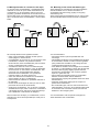
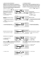
7.1 Controles disponibles
7.1 Available controllers
CDC 303: la producción de vapor se efectua de forma
TODO/NADA. El control prevee una entrada digital para la
conexión de una señal externa Todo/Nada, higrostato,
temporizador, etc. El único parámetro que se puede modificar es la producción máxima de vapor.
CDC 303: the steam production is ON-OFF. The controller
has an input for the humidity signal coming from any
ON-OFF external regulator. The only selectable parameter
is the maximum steam production.
Regulador On/Off
On/Off regulator
cdc
Umidificador ON
Humidifier ON
electric current
AMP
max production
Kg/h
configuration
water conductivity
µS/cmx10
Alarm
humidify on
Umidificador OFF
Humidifier OFF
fill
Alarm
drain
reset
drain
Contacto higrostato
Humidostat contact
sel
CDP 303: the steam production is modulating. The controller
has an input for the humidity signal coming from an external
modulating regulator. It can also be programmed by means of
the dip-switch selection, to receive at the input the signal coming
from the wide range of Carel regulators or from other modulating
regulators commonly available on the market. The only
selectable parameter is the maximum steam production.
CDP 303: la producción de vapor es modulante. El control
prevee una entrada, de señal modulante de un regulador
exterior. Mediante los dip-switch, el equipo se puede predisponer para reguladores Carel u otros. El único parámetro que se puede modificar es la producción de vapor.
Producción de vapor
Steam production
Regolador modulante
Modulating regulator
A
100
cdp
water conductivity
µS/cmx10
Alarm
humidify on
Alarm
reset
electric current
AMP
max production
Kg/h
configuration
fill
Producción de vapor introducida:
Steam production set at:
A: 100%
B: 50%
C: 30%
drain
B
C
30
drain
sel
SET
19
20% 30%
100% Señal regulador
modulante externo
External modulating
regulator signal
CDH 303: the steam production is modulating. It is the most
complete model and also includes the functions of modulating
regulator; therefore it is directly connected to the active probe of
humidity. It allows to display the humidity value measured by the
probe and to select the set-point and the differential.
CDH 303: la producción de vapor es modulante. Es el
modelo más completo, incluye funciones de regulador
modulante, por lo tanto se conecta la sonda (activa) de
humedad directamente. Permite la visualización en el
display, de la humedad medida por la sonda y es posible
la impostación del punto de consigna y del diferencial.
Producción de vapor
Steam production
Sonda activa HR%
Humidity active probe
cdh
relative humidity
%rH
water conductivity
µS/cmx10
Alarm
humidify on
Alarm
reset
electric current
AMP
max production
Kg/h
configuration
fill
drain
A
100
% U.R. humedad medida por la sonda B
%rH humidity value measured
by the probe
C
30
Producción de vapor introducida:
Steam production set at:
A: 100%
B: 50%
C: 30%
drain
sel
30% 20% SET
100%
%U.R./rH
DIFF
CDT 303: por lo que concierne a la regulación éste control
es idéntico al CDH303, la diferencia es que éste es conectado a una sonda (activa) de temperatura, en lugar de una
sonda de HR%. La aplicación típica de éste control es
para los baños Turcos (Vapor), y en general donde la temperatura pueda variar en función de la cantidad de vapor.
CDT 303: as regards the regulation this controller is identical
to the CDH303 except for its connection to a temperature
probe rather than to a humidity probe. The typical application
of this controller is in steam bath and generally in the
conditioned spaces where the temperature change
depends on the amount of steam being introduced.
CDD 303: la producción de vapor es modulante y además
existe un relé Todo/Nada, para la deshumidificación. La
función del regulador es prácticamente como el CDH303,
con la diferencia del relé para la deshumidificación. Éste
control está destinado para el control de la Humidificación
y Deshumidificación en centrales de tratamiento de aire y
es posible la combinación con el control MACROBASE.
CDD 303: the steam production is modulating and there is
an ON-OFF command for the dehumidification consent.
The regulator function is included. CDD 303 actually offers
the same functions as the CDH 303 and, furthermore, has
an ON-OFF transistor output for the dehumidification command. This controller has been designed to control humidification and dehumidification in air handling units and it is
compatible with the MACROBASE controller.
20
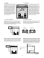
7.2 Frontal del regulador
7.2 Controller interface card
Las señalizaciones del control son:
Controller indications:
cdh
10
1
2
3
electric current
AMP
max production
Kg/h
configuration
relative humidity
%rH
water conductivity
µS/cmx10
Alarm
4
5
Alarm
8
14
fill
15
16
drain
reset
7
12
13
diff
set
humidify on
6
11
drain
17
sel
18
9
1.
2.
3.
4.
5.
6.
7.
8.
9.
10.
11.
12.
13.
14.
15.
16.
17.
18.
1.
2.
3.
4.
5.
6.
7.
8.
9.
10.
11.
12.
13.
14.
15.
16.
17.
18.
Humedad relativa o temp. medida por la sonda
Conductividad agua de alimentación
Estado de alarma
Punto Consigna
Humidificación en curso
Estado de alarma
Pulsador de Reset
Pulsador de selección
Pulsador incremento parámetros
Display de visualización
Corriente absorbida (instantánea)
Producción máx. de vapor
Configuración
Unidad de medida del valor visualizado
Llenado de agua en curso
Vaciado de agua en curso
Pulsador vaciado manual
Pulsador decremento parámetros
Valores de los parámetros
Relative humidity or temperature read by the probe
Fill water conducibility
Alarm condition
Selected set point
Humidification on process
Alarm condition
Reset button
Selection button
Parameter increase button
Display
Actual current (instantaneous)
Selected maximum steam production
Configuration
Selected differential
Ongoing water filling
Ongoing water drain
Manual drain button
Parameter decrease button
Selectable parameters
Parámetros
Valor
Parámetros de fábrica
Parameter
Value
Default
Producción max/Max production
Punto-consigna (H.R. o °C)/Set-point (%rH or °C)
Diferencial (H.R. o °C)/Differential (%rH or °C)
Limite alta (H.R. o °C)/High limit (%rH or °C)
Limite baja (H.R. o °C)/Low limit (%rH or °C)
Tipo vaciado/Type of drain
30%-100%
0-100
1-19
0-100
0-100
Cd o Td
70%
50
4
80
20
Cd
21
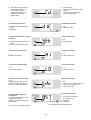
7.3 Secuencia de visualización
7.3 Display sequence
Mediante la presión del pulsador SEL, se pasa de una
visualización a otra, confirmando el valor introducido. La
visualización permanece durante 30 segundos, después de
éste tiempo, si no hay ninguna confirmación con el pulsador SEL, vuelve automáticamente a la visualización de funcio-namiento, sin haber memorizado el último parámetro
modificado. Los parám. son modifi-
By pressing the SEL button it is possible to go from one
display to another confirming the selected value. After 30 seconds, in the absence of confirmation through the SEL button,
the display is automatically restored, and the last modified
parameter is not stored. The selectable parameters can be
cados con los pulsadores
y
modified by the
and
buttons.
.
Visualización en el arranque
(aparece durante 2 segundos al
arranque del humidificador)
1. Mod.
2. Modelo del humidificador
3. Tipo de control
1
2
3
electric current
AMP
max production
Kg/h
configuration
relative humidity
%rH
Visualización durante el funcionamiento
– con control tipo CDH-CDT-CDD
1. Humedad relativa medida por la
sonda
2. Punto de consigna (Set-point)
3. Diferencial
1
2
3
Starting display
(it appears for 2 seconds when the
humidifier starts up)
1. Mod
2. Humidifier model
3. Type of controller
Working display
– with the CDH-CDT-CDD controllers
1. Relative humidity read by the probe
2. Set-point
3. Differential
electric current
AMP
– con control tipo CDC-CDP
1. Corriente absorbida (instantánea)
1
Producción máxima de vapor
1
– with the CDC-CDP controllers
1. Actual current (instantaneous)
max production
Kg/h
1. Steam production selection
(kg/h)
1. kg/h de producción de vapor
Visualización de configuración
1. Modelo humidificador
2. Alimentación
3. Número fases
electric current
AMP
max production
Kg/h
configuration
relative humidity
%rH
water conductivity
1µS/cmx10
Alarm
2
diff
set
3
Configuration display
1.
2.
3.
Humidifier model
Power supply
Phase number
Press the
button to enter to the next three configuration displays (by pressing the SEL button you will pass to
the next display).
Pulsar la tecla
para visualizar las tres pantallas sucesivas de configuración (pulsando la tecla SEL se pasa a
la pantalla de ajuste del diferencial).
1. Corriente nominal
2. Modelo TAM
Max steam production selection
electric current
AMP
max production
Kg/h
configuration
relative humidity
%rH
water conductivity
1µS/cmx10
Alarm
1. Nominal current
2. TAM model
2
1. Modelo control
electric current
AMP
max production
Kg/h
configuration
relative humidity
%rH
water conductivity
1µS/cmx10
Alarm
diff
set
22
1. Control model
1. Selección drenaje (vaciado)
Cd=drenaje (vaciado), con
electrodos en tensión
Td=drenaje (vaciado), con
electrodos sin tensión
(temporizado)
1
configuration
**Introducción diferencial
1. Humedad relativa medida por la
sonda
2. Diferencial
electric current
AMP
max production
Kg/h
configuration
1
electric current
AMP
max production
Kg/h
configuration
1. Humedad relativa medida por la
sonda
2. Punto de Consigna (Set-point)
1. HI
2. Valor límite de alta
electric current
AMP
max production
Kg/h
configuration
relative humidity
%rH
water conductivity
1µS/cmx10
Alarm
2
1. SEt
2. Set-point value
**High limit selection
1. HI
2. Value of high limit
1. LO
2. Value of low limit
diff
set
Switch off delay time
electric current
AMP
max production
Kg/h
configuration
relative humidity
%rH
water conductivity
µS/cmx10
1
Alarm
2
Conductividad del agua de
alimentación
1. Conductividad del agua de alimentación x 10µS/cm
2. Punto de consigna (Set-point)
3. Diferencial
**Set-point selection
**Low limit selection
electric current
AMP
max production
Kg/h
configuration
relative humidity
%rH
water conductivity
1µS/cmx10
Alarm
2
Tiempo de retardo a la parada
1. tdo
2. Segundos de retardo al paro
después de haber alcanzado el
Punto de Consigna introducido
1. dIF
2. Differential value
diff
set
**Introducción límite de baja
1. LO
2. Valor límite de baja
**Differential selection
2
**Introducción Punto de consigna
(set-point)
**Introducción límite de alta
1. Drain selection
Cd=drain with electrodes under
voltage
Td=drain without electrodes
under voltage (timed)
diff
set
electric current
AMP
max production
Kg/h
configuration
relative humidity
%rH
water conductivity
µS/cmx10
1
2
Alarm
diff
set
3
1. tdo
2. Seconds of max. delay from unit
swich off after reaching the
selected set-point
Fill water conductivity
1. Conductivity of fill water
(to multiply x 10)
2. Set-point
3. Differential
(**) with CDH-CDT-CDD controllers only
(**) sólo con control CDH-CDT-CDD
23
7.4 Conexionado a regulador y sonda
7.4 Connections to probes and regulators
Todos los humidificadores necesitan un mando externo
que habilite el funcionamiento, en base al tipo de control
utilizado se deberá conectar un regulador o una sonda.
All humidifiers require an external command enabling it to
operate. According to the type of controller you have to
connect a regulator, a humidostat or a probe.
Regulador Todo-Nada (ON-OFF) (humidificador con
control CDC)
ON-OFF regulators (humidifiers with CDC control)
+12
S1
56
-12
S2
57
58
59
+12 S1 S2
1 2 3456
on
off
60
56
57
58
-12
59
60
S90HP
S90RDH
Regulador
Humidostat
3
4
6
7
S90HW
8
Regulador
Humidostat
Carel modulating regulators (humidifiers with CDP
control)
Regulador modulante Carel (humidificador con
control CDP)
+12 S1 S2
G0
PE
56
57
58
1 2 3456
-12
59
+12 S1 S2
on
off
60
(*)
56
57
58
-12
59
60
0-10Vdc
A.OUT
Y
MACROPLUS
RUN040
RTH640
G0
REF
CR72 + CR72SER
24Vac
G
Regolador EXT
EXT regulator
Regulador EXT
EXT regulator
Carel active probes (humidifiers with CDH, CDD, CDT
controls)
Sonda activa Carel (humidificador con control CDH,
CDD, CDT)
+12 S1 S2
56
57
58
-12
59
60
1 2 3456
+12 S1 S2
on
off
56
57
58
1 2 3456
-12
59
60
on
off
4-20mA dc
0-1Vdc
SHWOOP0420
7
11
9
10
+
H
M
-
rojo
red
negro
black
marrón
brown
blanco
white
SHPOOP0000
SHWOOP0000
SSDOMH0000
SSDOHH0000
SAPOOA/P00
STHOAP0000
SSDOMHT000
SSDOHHT000
SSTOOB0000
SHPOOP00/1
SSWOHH00/1
SSDOMH00/1
SSDOHH00/1
STHONTC0/1
STHOAP00/1
SSWOHHT0/1
SSDOMHT0/1
SSDOMHHT0/1
SHWOOP00/1
7
11
9
+
H
M
Sonda
Sensor
Sonda
Sensor
24
DIP-SWITCH (Microrruptores)
La configuración de los dip-switch, indicada a continuación es para los modelos CDP y CDH, cuando la señal de
entrada no proviene de un instrumento Carel. Para algún
tipo de señal especial, se deberá hacer uso de una tarjeta
electrónica de conversión (suministrada a parte), pudiendo ser instalada dentro del humidificador.
DIP-SWITCH
The configuration the DIP-SWITCHES shown below are
for the CDP and CDH models when the input signals
come from NON Carel instrumentation. For certain type of
signals it is necessary to use special circuit adapter,
during the electric connections, that is supplied separately
and can be placed within the humidifier.
Regulador modulante No Carel (humidificador con
control CDP)
NON Carel modulating regulators (humidifier with
CDP control)
1 2 34 5 6
on
off
4-20 mA dc
G0
+12 S1 S2
PE
56
1 2 34 5 6
on
off
0-20 mA dc
57
58
-12
59
1 2 34 5 6
on
off
60
0-20 Vdc
(*)
G0
+12 S1 S2
PE
56
57
58
59
-12
1
2
3
5
4
60
(*)
taglio di fase / cut phase
1 2 34 5 6
1 2 34 5 6
on
off
on
off
2-10 Vdc
0-20 Vdc
+
Y
G
G0
1 2 34 5 6
Tarjeta conversión
CAREL (cod. AD10000000)
CAREL board adaptor
(code AD10000000)
out
on
off
regulador modulante
modulating regulator
(STÄEFA-INEL)
regulador modulante
modulating regulator
0-10 Vdc
NON Carel active probes (humidifier with CDH control)
Sonda activa No Carel (humidificador con control CDH)
1 2 34 5 6
on
off
1 2 34 5 6
on
off
0-20 Vdc
2-10 Vdc
G0
+12 S1 S2
PE
56
57
58
-12
59
60
(*)
1 2 34 5 6
on
off
0-10 Vdc
out
Sonda activa
active probe
-12
+12 S1 S2
56
57
out
58
+
Sonda 2 hilos
2-wire probe
59
CDH
68
60
6
7
G
69
1 2 34 5 6
on
off
4-20 mA dc
1 2 34 5 6
on
off
+12 S1 S2
56
57
58
-12
59
60
CDH
68
69
G
G0
0-20 mA dc
G0
out - +
Tarjeta conversión
CAREL (cod. AD10000000)
CAREL board adaptor
(code AD10000000)
Sonda 3 hilos
3-wire probe
6
7
Tarjeta conversión
CAREL (cod. AD10000000)
CAREL board adaptor
(code AD10000000)
(*) The electrical panel of the humidifier features the
ground connection of the internal reference G0 of the controller by the transformer secondary (see terminal 69 to
PE). Connection of the external signal: the humidifier controller internally shares the 59 and 69 terminals (reference
to PE). Equipotentiality between the 58 and 59 terminals
is required. Consequently, the external regulator connected to 58 must be equipotential to the PE terminal, or else
isolated from it.
(*) En el cuadro eléctrico del humidificador prevee el
conexionado a tierra de la referencia interna GO, del control y del secundario del transformador (ver borne 69 al
PE). Conexionado de la señal exterior: el control del humidificador necesita la referencia al borne 58. En el mismo
control internamente hay un común y los bornes 59 y 69,
conectados al GO (Referencia PE). Entre los bornes 58 y
59 del control debe haber el mismo potencial. En consecuencia el regulador externo se tendrá que referenciar al
borne PE, o bien aislarlo del mismo.
25
7.5 Conexionado serial
7.5 Serial connection
Conexionado serial, todos los controles descritos están
dotados de la predisposición serial. Mediante el interface
serial (opcional) ASM2, que es posible instalarla en el
interior del humidificador, se puede acceder a una red de
comunicación RS422. Utilizando el sistema de supervisión
Carel, desde el PC, de supervisión será posible no sólo
monotorizar el estado del equipo, (alarmas, valores de la
Hr%, vaciado, etc), si no también modificar los parámetros, lo que dispondremos de una completa gestión de los
equipos a distancia.
All the controls previously illustrated have the serial
predisposition. By means of the optional serial interface
ASM2, to be placed inside the humidifier, the network
connection RS422 is possible using the Carel supervisory
systems. From the supervisory computer it will be possible
not only to monitor the machine condition (alarms, value
of the controlled quantities, intervention threshold etc.) but
also to change parameters, in order to carry out a complete remote handling of the installations.
serial converter
CS
C1
CT
C1
C1
DV
C2
C2
C4
cd*
drain
sel
ASM2
C4
DV
C2
cod. ASM2000000
cod. 98C145C034
ASM2
C4
C4
reset
drain
sel
C4
cd*
cd*
reset
C2
ASM2
cd*
reset
DV
C2
ASM2
ASM2
C1
DV
DV
drain
reset
drain
sel
sel
ordenador personal (no suministro Carel)
personal computer (not available)
C1 cod. 98C145C024
CS cod. CONV422CL1
CT cod. 98C145C025
Para conectar en red más de 15 humidificadores, se
debe utilizar la tarjeta multiserial cod. MULTISER40
To connect by network more than 15 humidifiers, you must
utilize the multiserial board code MULTISER40
26
8. Guía de puesta en marcha
8. Start up
8.1 Controles preliminares
8.1 Preliminary checks
Antes de poner en marcha un Humidificador SD, se debe
efectuar algunos controles preliminares:
• las conexiones eléctricas de alimentación;
• el conexionado de la sonda o regulador y el On-Off
remoto;
• el tubo de conducción de vapor, no debe estar obstruido
a lo largo de la instalación;
• la llegada del agua al humidificador;
• el conexionado al desagüe;
• central (o conducto de aire) de tratamiento, debe ser
totalmente operativa.
Before starting up a SD humidifier, check the following:
• power supply electrical connections;
• connection of the probe (or regulator) and remote
ON-OFF;
• the steam duct must not be narrowed in any part;
• water supply to the humidifier;
• drainage connection;
• unit (or air duct) of treatment fully operative;
8.2 El encendido
8.2 Turning on
Actuar sobre el interruptor situado debajo del control frontal. Sobre el display del control el cursor (triangulo), se
posicionará automáticamente sobre la indicación “ELECTRIC CURRENT” en los modelos CDC y CDP, sobre la
indicación “RELATIVE HUMIDITY”, en los modelos
CDH,CDD y sobre la indicación “TEMPERATURE” en el
modelo CDT. Simultáneamente es visualizado el valor
medido. Si al humidificador se le pide vapor, se encenderá
el LED verde de “HUMIDIFY ON” y el LED naranja “FIL”’.
En el primer caso indica que está humidificando, y el contactor de potencia está conectado, en el segundo caso
nos indica que está entrando agua, mediante la apertura
de la válvula de solenoide.
Press the switch placed below the control panel. On the
display of the control the slider (small triangle) will automatically
position itself on the indication “ELECTRIC CURRENT”, in
the CDC and CDP models, on the indication “RELATIVE
HUMIDITY”, in the CDH and CDD models or on the indication “TEMPERATURE” on the model CDT.
Simultaneously, their measured value is being displayed.
If humidification is needed the green LED of “HUMIDIFY
ON” and the orange LED of “FILL” will light up on the control.
In the first case it is indicated that the machine is
humidifying because the power contactor is enabled, in
the second one, on the contrary, it is indicated that it is fill
water through the opening of the solenoid valve.
Una vez que el humidificador haya arrancado verificar:
• que el distribuidor lineal de vapor, instalado en el
conducto, recoja bien los condensados y que la
conexión del tubo de vapor no tenga pérdidas ni haya
goteo dentro del canal, por problemas de condensación,
• después de unos minutos de funcionamiento, verificar
que no haya aparecido ninguna alarma en el display del
control,
• que el humidificador funcione sólo cuando el ventilador
de la central de tratamiento de aire esté en marcha,
• cuando esté excitada la válvula de llenado/vaciado, haya
una aportación de agua o un vaciado según el caso.
Once the humidifier has been started up check that:
• from the linear steam distributor, that is inserted in the
piping, come out the condensed water from the air bleeder
located in the distributor and there is no dripping in the
duct;
• after a few minutes of operation no alarm is shown on
the control display;
• the humidifier operates only where the fans of the unit
are active;
• when the fill/drain valve is excited, there is actually a
water inflow/outflow to/from the cylinder.
Note: When the water conductivity is less than 400µS, the
humidifier could reach full efficiency within a few hours.
Nota: Si la conductividad del agua fuese inferior a 400µS,
el humidificador puede necesitar varias horas para estar a
pleno régimen.
Funcionamiento humidificador sin regulación
externa
Functioning of the humidifier without external
regulation
N.B. Se recomienda seguir las operaciones siguientes
con el humidificador parado.
N.B. It is advisable to do the following operations with the
humidifier OFF.
CDH desconectar la sonda - posicionar el microinterruptor 1 en ON los demas en OFF.
CDP desconectar el regulador modulante - posicionar
los microinterruptures 2,6 en ON, los demas en
OFF - hacer un puente entre los bornes 56-57 y
otro entre los bornes 58-59.
CDC desconectar el humidostato - verificar la posicion de
los microinterruptures 4,6 en ON; los demas en OFF
- hacer un puente entre los bornes 56-57 y otro entre
los bornes 58-59.
CDH disconnect the probe - position dip-switch 1 ON the
others OFF.
CDP disconnect the modulating regulator-position dip-switch
2.6 ON the others OFF – insert a jumper between
the terminals 56-57 and another one between the
terminals 58-59.
CDC disconnect the humidostat – check the positioning
dip-switch 4.6 ON and the others OFF – insert a
jumper between 56-57 and another between the
terminals 58-59.
27
8.3 Introducción parámetros fundamentales
8.3 Selection of the main parameters
Como se ha dicho anteriormente, algunas indicaciones
que aparecen en el display son sólo lecturas de unidades
de medida, mientras que otras son parámetros modificables por el usuario.
As previously said, some displayed indications are to be
read only, while some others can be modified by the user.
The parameters that can be modified are:
• CDC and CDP control: maximum steam production and
type of water drain (under voltage or in time).
• CDH,CDT and CDD controllers: besides the above
mentioned parameters also set-point, differential,
low and high humidity limit.
Los parámetros modificables son:
• control CDC y CDP: producción máxima del vapor y
tipo de vaciado del agua (en tensión o tiempo)
• control CDH,CDT y CDD: Los parámetros anteriormente
descritos y además el Punto de Consigna (Set-Point),
diferencial, límite alto y bajo de la humedad.
For a more detailed explanation of how the control operates see chapter 7.3 – Display sequence.
Para una explicación más detallada sobre la operativa del
control, ver el capítulo 7.3.
• La parte hidráulica del humidificador no es necesario
ningún tipo de ajuste.
• The hydraulic part of the humidifier does not require any
type of calibration.
9. Mantenimiento
9. Maintenance
9.1 Componentes a controlar o sustituir
9.1 Components to be controlled or replaced
En el humidificador a vapor sólo hay un órgano que debe
ser sustituido periódicamente: el cilindro de producción
de vapor. Esta operación es necesaria cuando la incrustación calcárea que se produce en el interior del cilindro,
impide el suficiente paso de corriente por los electrodos.
Esta situación esta señalada por el control, con la alarma
E08. La frecuencia de esta intervención, depende de la
calidad del agua de alimentación: agua más rica en sales
o impurezas, sustitución del cilindro de producción con
más frecuencia.
The steam humidifier has only one component which
requires a periodical replacement: the steam production
cylinder. This is necessary where the limestone scales
that build up inside the cylinder prevent a sufficient flow of
current. This situation is indicated by the control with the
E08 alarm. The frequency of this operation depends on
the fill water: the higher the content of salts and impurities,
the more frequent will be the cylinder replacement.
Los órganos que deben ser controlados una vez al
año son:
The components to be checked yearly are:
Electroválvulas de llenado, vaciado, bomba de desagüe:
limpiar de las eventuales incrustaciones sólidas, (no utilizar aire comprimido) y verificar el funcionamiento.
Fill/drain solenoid valve, drain pumps:
remove possible solid scales, without compressed air, and
check the proper operation.
Circuito hidráulico/bandeja de carga:
limpiar las eventuales incrustaciones, del circuito del agua
desde la salida de válvula de llenado hasta la entrada en
el cilindro, y verificar que no haya pérdidas de agua ni
goteos.
Hydraulic circuit/fill tank:
remove possible scales along the while distance covered
by water from the fill valve to entrance into the cylinder.
Afterwards check that there are no leaks or drips.
Tubo de conducción del vapor/recogida de condensados:
comprobar que a lo largo del tubo no existan obstrucciones, que impidan circular libremente el vapor o los condensados.
Steam pipe/condensation drainage:
check that from its beginning (the humidifier) to its end
(the distributor) in duct or ambient, there are no narrowings, thus preventing the normal output of the steam/
condensation.
Sonda de humedad:
controlar el estado de la sonda y eventualmente requilibrar. No utilizar aire comprimido ni disolvente, para la limpieza del sensor.
Humidity probe:
check the condition of the probes and, if necessary, calibrate them. Do not use compressed air or solvents to
clean the probe sensors.
Atención: si el equipo se tiene que dejar fuera de servicio, vaciar completamente el agua del cilindro productor de vapor.
Caution: when out of order, drain completely the
cylinder water.
28
9.2 Cylinder replacement
9.2 Sustitución del cilindro
Para desmontar el cilindro seguir
el procedimiento que a continuación se indica.
To remove the cylinder operate
as follows.
• Vaciar completamente el agua,
apretando el pulsador “Drain”
del control.
• Drain thoroughly the water by
pressing the “DRAIN” button
of the control.
• Interrumpir la alimentación
eléctrica del humidificador
mediante el interruptor
(comprobar que el humidificador ha sido desconectado de
la red).
• Cut off the power supply to
the humidifier by means of
the power switch.
ATTENZIONE!
ATTENTION!
Desconectar el
humidificador
de la red principal
Disconnect the
humidifier to the
electrical network
• Remove the steam pipe from
the cylinder.
• Sacar el tubo de vapor del
cilindro.
29
• Desconectar las conexiones
eléctricas de los electrodos y
sacar los terminales de las
espigas de alto nivel.
• Disconnect the electrical
connections to the electrodes
and remove the plugs from
the high level electrodes.
• Desenroscar el tornillo/pomo
de fijación del soporte de
bloqueo del cilindro.
• Remove the fastening knob
of the cylinder fixing bracket.
• Levantar el cilindro para
extraerlo.
• Lift the cylinder to pull it out.
30
• Unscrew the ring nut to
remove the hub and filter
(filter available in the cylinders
type E, F).
• Desenroscar la tuerca, para
sacar el “bochettone” y el filtro
(filtro sólo presente en los
cilindros tipo E, F).
• El cuerpo del filtro no necesita ser sustituido, se debe
lavar bien con agua y montado en el nuevo cilindro,
utilizando la junta que viene con el cilindro.
• The filter has not to be replaced. Therefore wash it
with water and mount it again on the new cylinder using
the new gasket supplied with the same.
• Montar el cilindro en el humidificador, siguiendo los
pasos anteriormente descritos, pero en sentido inverso.
• Reassemble the boiler in reverse sequence.
Destrucción del cilindro (Reciclado de materiales)
Disposal of the cylinder
• Cortar el cuerpo del cilindro a lo largo de la circunferencia, mediante un objeto adecuado (sierra, cutter, etc).
• Cut the plastic shell along the circumference by means
of a hack-saw.
• Desenroscar los electrodos, del interior del cilindro.
• Unscrew the electrode fixing nuts located on top outside
the cylinder.
• Sacar del interior los electrodos metálicos, separando
las partes de plástico que hubiera.
• Remove from inside the metal electrodes and separate
them from the possible plastic support.
La parte de plástico, está compuesta por Polipropilene, el
cual es totalmente reciclable, y va destinada a la recuperación de materia plástica.
The plastic part is made of polypropylene, and therefore,
throughly recyclable, must be sent to plastic recovery.
La parte metálica, es Fe37, por lo tanto va destinada a la
recuperación de materiales ferrosos.
The metal part is made of sheer metal Fe37. Therefore it
must be sent to metal recovery.
31
10. Funcionamiento
10. Functioning
10.1 Principio de funcionamiento
10.1 Basics on functioning of the machine
El humidificador de electrodos sumergidos, funciona por
el efecto JOULE, utilizando el agua del interior del cilindro, como resistencia eléctrica: el agua es calentada
hasta llegar a su ebullición, produciendo vapor de agua.
Al aumentar el nivel de agua en el interior del cilindro,
disminuye la resis-tencia eléctrica, por lo que aumentaremos la corriente absorbida. La corriente absorbida es
directamente proporcional a la producción de vapor. Para
evaporar un litro de agua/hora son necesarios 0,725 Kw.
El control del equipo, conociendo la tensión en bornes, el
número de fases y la producción nominal de vapor,
gestionara el humidificador en todo momento.
The immersed electrode humidifier works according to the
Joule effect utilizing the water itself as an electric resistance:
the water being heated up to the boiling point evaporates.
As the water level in the cylinder increases, the resistance
also increases and therefore the current being absorbed.
The absorbed current is proportional to the production of
steam. In fact, for the evaporation of one litre/hour of
water 0.725kW are needed. Thus, when the control knows
the voltage, the phase number and the nominal production of steam can manage the humidifier.
For example, a SD305H0380 supplied with 380Vac, 3-phase
that produces 5kg/h of steam, absorbs 1.1 Ampere per
kg/h of produced steam. Therefore, when it absorbs 5kg/h
of steam it absorbs 5.5 Ampere.
Por ejemplo un humidificador SD305H0380, alimentado
con una tensión de 380 Vac-III-, que produce 5 Kgr/h de
vapor, absorbiendo 1,1 Amp. por Kgr/h de vapor producido. Cuando produzca 5,5 Kgr/h, consumirá 5,5 Amp.
When humidity is needed by the ambient, the electronic
control activates a power contactor which enables the flow
of current till the electrodes immersed in the water. The
production of steam set on the control is reached and
controlled by measuring the absorbed current with the
amperometric transformer (TAM). When the production of
steam goes below the selected value, as a result of water
evaporation, the control commands the fill solenoid valve
that fills the water into the fill thank, in the humidifiers up
to 13kg/h, from which it flows due to the water column difference in the cylinder. For the humidifiers from 23 to
126kg/h, without fill tank, the water flows into the cylinder
going before through an hydraulic circuit so as to permit a
pressure equilibrium between the ambient and the machine.
Cuando es necesario aportar humedad, el control electrónico activa un contactor de potencia el cual permite el
paso de la tensión hasta los electrodos sumergidos en el
agua. La producción de vapor introducida en el control, el
trans-formador amperimétrico (TAM), mide en todo
momento la corriente absorbida. Cuando la producción de
vapor desciende por debajo del valor impostado en el
control, se abre la válvula de llenado, restableciendo su
nivel y por lo tanto la producción de vapor. En los humidificadores hasta 13Kgr/h, el agua entra en el cilindro por
diferencia de columna de agua, entre la bandeja de llenado y el cilindro. Para los humidificadores de 23 a 126
Kgr/h, no dotados de bandeja de carga, el agua entra
directamente en el cilindro, a través de la válvula de llenado, es necesario mantener una presión de agua superior
a la presión interna del cilindro.
The partialization of the steam production, handled by the
CDH, CDD and CDT controls, is carried out through the
control of water level inside the cylinder. Thus, depending
on the selected set-point and differential, the steam production
changes within the proportional band of choice (differential) (see parag. 7.1 on page 19).
La modulación de la producción del vapor, se gestiona
por los controles, CDH, CDD y CDT, se realiza mediante
el control del nivel del agua en el interior del cilindro, consiguiendo una acción proporcional sobre la producción de
vapor, de acuerdo con el punto de consigna y el diferencial impostados (ver apartado 7.1, pag.19).
The hydraulic circuit has two electrodes for the detection
of the fill water conductivity, useful for the electronic control to optimize the humidifier operation according to the
dielectrical characteristics of the fill water. On the top of
the cylinder two high-level little electrodes are found:
these sensors check that the water level does not exceed
the maximum value beyond which it would be drained
through the overflow pipe.
El circuito hidráulico, está dotado de dos electrodos para
medir la conductividad del agua de alimentación, medida
que utiliza el control electrónico, para optimizar el funcionamiento del humidificador, adaptándolo a las características dieléctricas del agua de alimentación. En la parte
alta del cilindro, hay dos pequeños electrodos de alto
nivel, estos dos sensores controlan que el nivel del agua
no supere el valor máximo.
The drain solenoid valve in the humidifiers up to 13kg/h
and the drain pumps for those from 23 to 126kg/h, is activated
by the control, with a frequency that depends on various
factors in order to keep the optimal salt concentration in
the cylinder, to allow a regular operation of the machine.
La electroválvula de vaciado, se monta en los humidificadores hasta 13 kg/h, a partir de éste modelo es montada
una bomba de vaciado, el accionamiento de la válvula o
bomba de vaciado, es ejecutada por el control, con una
frecuencia ligada a una serie de factores (conductividad
del agua, horas de funcionamiento, etc), con el fin de
mantener en óptimas condiciones las concentraciones
salinas dentro del cilindro, y mejorar el rendimiento de la
máquina.
The operation principle is the same for all the humidifiers;
however it must be remembered that in the multicylinder
humidifier there is only one control that handles an interface
card which simultaneously manages the various cylinders
with their valves and pumps autonomously.
El principio de funcionamiento es único para todos los
humidificadores, en los humidificadores que montan más
de cilindro, existe una tarjeta interface que gestiona
simultáneamente todos los cilindros, aunque la válvula y
la bomba de vaciado funcionan de forma autónoma.
Finally, the new AFS (anti foaming system) smart
algorithm can detect and eliminate the foam through
special work cycles.
El nuevo algoritmo inteligente AFS-ANTIFOAMING
SYSTEM, permite eliminar la espuma, mediante unos
ciclos particulares de trabajo.
32
11. Alarmas y prealarmas
11. Alarms and pre-alarms
El control del humidificador, puede reconocer las situaciones anómalas de funcionamiento y de alarmas graves.
Todas las anomalías son codificadas y mostradas en el
display del control, para poder intervenir sobre el humidificador correctamente.
The humidifier controller can detect anomalous working
conditions and serious alarms. All the anomalies are
coded and shown on the display so as to act properly on
the humidifier.
11.1 Prealarmas
11.1 Pre-alarms
Son las que indican que el humidificador, no está trabajando en condiciones normales, pero sin interferir en el
normal funcionamiento del equipo. Las prealarmas por
consiguiente no bloquean el funcionamiento del humidificador, son señaladas mediante una flecha en el display,
indicando la palabra “Alarm”, sobre el policarbonato. No
obstante es posible ver el código de la prealarma, apre-
The purpose of the pre-alarms is to inform the user that
the humidifier is not normally operating, without interfering
with the normal functioning of the humidifier. Therefore the
pre-alarms do not stop the operation but signal its presence
through the lighting of the cursor in the display of the controller
connected with the “alarm” word on the controller.
Notwithstanding this, it is possible to find the pre-alarm
tando el pulsador
code by pressing the parameter-increase button
found on the keyboard of the controller.
de incremento de valores.
to be
11.2 Alarmas
11.2 Alarms
Las alarmas, son detectadas en el momento de aparecer
una situación particular de mal funcionamiento, generalmente son precedidas de alguna prealarma (a excepción
de E11, E12, E32). Las alarmas comportan:
• visualización en el display del código de la alarma;
• bloqueo del funcionamiento del humidificador;
• activación del relé de alarma;
• vaciado total del agua del cilindro (a excepción de las
alarmas E11, E12; E31, E32).
An alarm results from a continuous anomalous working
condition.
In case of alarm the following conditions occur:
• the relevant code is displayed;
• stop of the humidifier operation (except for the E11,
E12);
• energization of the alarm relay;
• complete water drain (except for the E11, E12, E31
and E32 alarms).
Apretando el pulsador RESET, después de una alarma el
humidificador volverá a funcionar. Si la alarma aún persiste, el equipo en breve tiempo se volverá a bloquear. Se
aconseja en todo caso, antes de volver a apretar el pulsador de RESET, consultar el capítulo “Que hacer sí…”
donde se dan algunas sugerencias, que les permitirán
probablemente solucionar la anomalía, evitando pérdidas
de tiempo, y daños mayores al equipo. El pulsador de
RESET, no tiene ningún efecto en presencia de alguna
prealarma.
By pressing the push-button RESET following an alarm,
the humidifier starts again. However, if the cause of the
alarm persists, within a short time the humidifier will stop
again. In any case, it is advisable, before trying to restart
the humidifier by pressing the RESET button, to consult
the checkings suggested in the next chapter
“Troubleshooting...”, in order to avoid unnecessary loss of
time or actions that may damage the unit.
The RESET button has no effect if used in the
presence of a pre-alarm.
33
12. Ricerca ed eliminazione dei guasti
12. Troubleshooting
E03 - Evolución espumosa
E03 - Foaming of boiling water
El control ha detectado espuma en el interior del cilindro.
The controller has detected foam inside the cylinder
Causa
1 Particular característica del agua
2 Impurezas ligadas a la nueva línea de alimen. del agua
3 Contrapresión en el envío de vapor
Cause
1 Particular characteristics of the water
2 Impurities left by the new line of fill water
3 Backpressures in the steam duct
Verificación y solución
1-2 El control puede gestionar y eliminar el problema:
verificar que el tratamiento agua sea el correcto
3 Verificar que el tubo de conducción del vapor, no esté
obstruido o con alguna bolsa de agua de
condensación
Checkings and solutions
1-2 The controller is self managing and can eliminate the
problem: check that the treatment of the water is not
excessive
3 Check that the steam pipe is not narrowed in its
length and for the presence of condensation inside.
E06 - Sobrecorriente
E06 - Current too high
Cuando la corriente supera el valor de seguridad, 170%
de la Intensidad nominal
When the current exceeds the safety threshold 170% I.nom.
Cause
1 Bridge of limestone between the electrodes
2 Leakage of the fill valve (during the stop phase)
3 The drain valve/pump(s) does not work
Causa
1 Puente calcáreo entre los electrodos
2 La válvula de llenado no cierra correctamente
(en la fase de no carga)
3 No funciona la válvula/bomba de vaciado
Checkings and solutions
1 Check the cylinder
2 Check the fill valve (see E14)
3 Check the drain valve
Verificación y solución
1
2
3
Sustituir el cilindro
Sustituir la válvula de llenado (ver E14)
Sustituir la válvula/bomba de vaciado
E08 - Cilindro agotado
E08 - Exhausted cylinder
Cuando el humidificador no puede producir la cantidad de
vapor programado.
When the humidifier can not produce the selected amount
of steam
Causa
Cilindro totalmente saturado de depósitos calcáreos.
Cause
Cylinder covered with limestone deposits
Verificación y solución
Sustitución/Limpieza del cilindro
Checkings and solutions
Cleaning/replacement of the cylinder
E09 - Falta de agua
E09 - Lack of water
Cuando la electroválvula de llenado permanece abierta
durante 20 minutos, sin o con poco consumo de corriente
When the fill solenoid valve remains open for 20 minutes
in the absence of or with a reduced current
Causa
1 Falta de agua en la red o presión insuficiente
2 Electroválvula de llenado bloqueada
3 Contrapresión en la salida del vapor
4/5 Obstrucción en el circuito hidráulico de llenado
Cause
1 Lack of water in the piping or insufficient pressure
2 Block of the fill water valve
3 Backpressure in the steam pipe
4-5 Blockage of the hydraulic circuit of water fill (the water
keep flowing out of the fill tank over flow)
Verificación y solución
1 Verificar que haya presión de agua de alimentación al
humidificador
2 Controlar la válvula de llenado (filtro)
3 Verificar que no esté obstruido el tubo de conducción
de vapor
Checkings and solutions
1 Check for presence and pressure of fill water to the
humidifier
2 Check the fill solenoid valve (filter)
3 Check for a possible obstruction of the fill-water
hydraulic circuit from the tank to the cylinder
34
E10 - Falta de corriente
E10 - Lack of current
Cuando el sensor de potencia TAM, no registra ningún
paso de corriente y el agua está en alto nivel
When the power sensor TAM does not record flow of current and water reaches the top level
Causa
1 Uno o más electrodos no hay tensión
2 Transformador amperimétrico TAM, dañado
3 Contactor de potencia estropeado
4 Cilindro productor totalmente agotado
5 Nivel alto en cortocircuito
Cause
1 One or more electrodes not alive
2 Faulty amperometric transformer
3 Faulty contactor
4 Cylinder fully exhausted
5 High level in short circuit
Verificación y solución
1 Verificar que llegue tensión a todos los electrodos
2 Verificar que entre los bornes 54-55, aparezca una
tensión de 0 y 2 Vac, según la producción del momento
3 Verificar el contactor
4 Sustituir el cilindro productor
5 Verificar el recorrido de los cables de conexion de
nivelalto
Checkings and solutions
1 Check for the presence of current at all the electrodes
2 Check that between the 54-55 terminals there are 0÷2Vac
3 Check the contactor
4 Replace the cylinder
5 Check the wiring of the high level electrodes
E11 - Alta humedad
E11 - High humidity
Cuando la humedad supera el límite prefijado (HI)
When the humidity exceeds the selected limit (HI)
Causa
La humedad relativa medida ha superado el umbral HI
Nota: El humidificador está retardado 20” a la puesta en
marcha
Cause
The relative measured humidity has exceeded the HI
N.B: the alarm has a delay of 20 minutes at starting up
Verificación y solución
Verificar que el umbral del límite de alta humedad HI,
haya sido fijado a un valor idóneo para la aplicación
Checkings and solutions
Check that the HI high humidity limit has been set at a
value suitable for the application
E12 - Baja humedad
E12 - Low humidity
Cuando la humedad desciende por debajo del umbral LO.
When the humidity goes below the selected limit LO
Causa
1-2 La humedad relativa medida es inferior al umbral LO
N.B. La alarma esta retardada 20 min. tras el arranque
Cause
1-2 The measured relative humidity is below the LO threshold
N.B: the alarm has a delay of 20 minutes at starting up
Verificación y solución
1 Verificar que el límite de baja humedad LO, haya sido
fijado a un valor idóneo para la aplicación
2 Verificar que no haya sido abierta alguna puerta o
ventana
Checkings and solutions
1 Check that the low humidity limit LO has been pre-set
at a value suitable for the application
2 Check that neither windows nor doors have been opened
E14 - Error de conversión
E14 - Error of conversion
Cuando la conversión de los valores analógicos de entrada (sonda, conductímetro, TAM), fallan.
La alarma E14, puede aparecer en secuencia o en alternancia con la alarmas, E31 y E06.
When the conversion of the analog input values (probe,
conductimeter, TAM) fails
E14 can appear in sequence or alternatively with the
alarm E31 and E06
Causa
1 Sonda/regulador mal conexionado
2 Dip switch, incorrectamente configurados, según las
señales usadas
3 Dip switch, invertidos
4 Sonda con valores fuera de rango
5 Señal sonda/regulador con fuertes interferencias
electromagnéticas
Cause
1 Probe/regulator disconnected
2 Dip switches not properly configured according to the
signal in use
3 Inverted dip switches
4 Probe with out of range values
5 Probe/regulator signal with electromagnetic interferences
Checkings and solutions
Operate the humidifier without connecting any external
regulator (see humidifier operation without external
regulation)
1 Check the probe/regulator connections
2-3 Check dip-switch selection
4 Check for out-of-range signals by probe/regulator
5 Be careful when laying the probe/regulator connection
cable (they must not be near power supply
cables/contactors)
Verificación y solución
Hacer funcionar el humidificador, sin conectar ninguna
regulación externa (ver apartado del funcionamiento sin
regulación externa)
1 Verificar y conectar sonda/regulador
2-3 Verificar la posición de los Dip-switch
4 Verificar que la sonda/regulad. no esté fuera de rango
5 Atender la instalación de los cables de conexión
sonda/regulador (no deben instalarse cerca de cables
de potencia, contactores, relés
35
E31 - Mal funcionamiento sonda/regulador externo
E31 - Malfunctioning probe/external regulator
Cuando la señal de sonda/regulador externo, dan una
señal fuera de rango
Ver E14
When the probe/regulator signal takes out-of-range values
See E14
Funcionamiento del humidificador sin regulación externa
Functioning of the humidifier without external
regulation
NOTA: se recomienda seguir las operaciones siguientes
con el humidificador parado
N.B. It is advisable to do the following operations with the
humidifier OFF
CDH Desconectar la sonda- colocar los dip-switch: 1
ON, resto OFF
CDP Desconectar el regulador modulante- colocar los
dip-switch: 2, 6 ON resto OFF, efectuar un puente
entre los bornes 56-57 y 58-59
CDC Desconectar el higrostato- colocar los dip-switch: 4,
6, ON resto OFF, efectuar un puente entre los
bornes, 56-57 y 58-59. Llegado a éste punto,
alimentar el humidificador, en el supuesto que
funcionara, verificar lo descrito en E14
CDH disconnect the probe - position dip-switch 1 ON the
others OFF
CDP disconnect the modulating regulator-position dip-switch
2.6 ON the others OFF – insert a jumper between
the terminals 56-57 and another one between the
terminals 58-59.
CDC disconnect the humidostat – check the positioning
dip-switch 4.6 ON and the others OFF – insert a
jumper between 56-57 and another between the
terminals 58-59.
E32 - Autotest fallido
E32 - Autotest failure
Sistema de adquisición de datos de la memoria interna no
efectuado
Causa
1 Hardware dañado
2 Control no programado
The system does not acquire data from the internal
memory
Cause
1 Faulty hardware
2 Not programmed control
Verificación y solución
1-2 Reprogramar el control, por vía serial, mediante el
programa de configuración CAREL
Checkings and solutions
1-2 Program again the controller via serial line through
the Carel configuration program
En el humidificador no se iluminan los Leds
The humidifier does not start
No llega tensión al cuadro eléctrico
No current at the electrical panel
Causa
La alimentación general está desconectada
Cause
General power supply not energized
Verificación y solución
Verificar la protección, montada en el humidificador
Checkings and solutions
Check the protection upstream to the humidifier
El control no está alimentado
No power supply to the controller
Causa
1 Conector del control mal introducido
2 Contacto ON/OFF, remoto (bornes 20-21), abiertos
3 Salida del transformador estropeada
4 Interruptor del panel abierto
5 Fusible fundido
Cause
1 Control connector not properly inserted
2 Remote ON-OFF contact (terminals 20-21) open
3 Transformer output fault
4 Panel switch open
5 Fuses broken
Verificación y solución
1 verificar que el conector del control esté bien introduc.
2 Verificar el estádo On-Off (bornes 20-21, efectuar
puente)
3 Verificar que en el secundario del transformador haya
24 Vac
4 Cerrar el interruptor del panel
5 Verificar el estado de los fusibles primario/secundario,
F1-F2-F3
Checkings and solutions
1 Check that the connectors are correctly inserted
2 Check ON-OFF conditions (terminals 20-21 bridged)
3 Check that at the secondary of the transformer there
are 24Vac
4 Close the panel switch
5 Check the fuse conditions at the primary/secondary
F1, F2, F3
36
El humidificador no arranca
The humidifier does not start
CDC-CDP: el control muestra 0.0 Amp. y no arranca.
CDC-CDP The controller shows 0.0 Amp. and does not start
Causa
1 No llega la señal externa al humidificador
2 No ha sido conectado correctamente el regulador/
higrostato o sonda exterior
3 Los dip-switch, no han sido program. correctamente
Cause
1 The external signal does not reach the humidifier
2 Not correct connection external regulator/humidostat
or probe
3 Dip-switches not correctly positioned
Verificación y solución
1 Verificar que entre los bornes 57-58, del control llega
señal(*)
2 Verificar el conexionado externo
3 Posicionar correctamente los dip-switch
*Nota: ver “Funcionamiento humidificador sin regulación
externa”, página 36
Checkings and solutions
1 The contact of the external humidistat must be closed
between the terminals 57 and 58 of the humidifier controller (*)
2 Check the external connection
3 Position correctly again the dip-switches
*Note: see “Humidifier operation without external
regulation” on page 36
CDH-CDT-CDD: El control muestra el valor de la sonda,
pero no arranca
CDH-CDT-CDD: the control shows the value read by the
probe but does not start
Causa
Punto de consigna es muy bajo
Cause
The selected set-point is too low
Verificación y solución
Subir el punto de consigna
Checkings and solutions
Raise the set-point
El humidificador llena y vacia el agua continuamente sin producir vapor
The humidifier continuously fills and drains and
does not produce steam
Cause
1 Bridge of limestone inside the cylinder
2 Backpressures in the steam pipe
3 Breakage of the flow regulator of the water fill valve
(possible leakage in the hydraulic circuit)
4 Very high conductivity of the fill water
Causa
1 Puente calcáreo dentro del cilindro
2 Contrapresión en la salida de vapor
3 Rotura del regulador de flujo de la válvula de llenado
de agua (posible pérdida en el circuito hidráulico)
4 Conductividad del agua de alimentación muy alta
Verificación y solución
1 Substituir el cilindro
2 Verificar que el tubo de conducción de vapor no
presente retenciones por pliegues o similares y que
existan sifones
3 Substituir la válvula de llenado
4 Verificar la conductividad del agua y corregir
Checkings and solutions
1 Replace the cylinder
2 Check that the fill vapour duct is not narrowed or bent
3 Replace the fill valve
4 Check the conductivity of the fill water
La cantidad de vapor preseleccionada, no se
produce
The selected quantity of steam is not produced
Cause
1-2 Very low conductivity of the fill water (absorbed current
below the pre-set values with high activated level)
Causa
1-2 Conductividad del agua de alimentación muy baja
(Corriente absorbida por debajo del valor prefijado,
con la alarma de alto nivel activada)
Checkings and solutions
1 Wait for a few hours
2 Replace the cylinder with another one specific for low
conductivity
Verificación y solución
1 Atender la evolución durante algunas horas
2 Substituir el cilindro por uno específico de baja
conductividad
Breakage of the differential switch of the
electrical circuit
Cae el diferencial del circuito eléctrico
Causa
1 Existe una dispersión de corriente, con referencia al
tierra y la descarga de agua
2 Existe una dispersión de corriente, con referencia al
tierra y la conducción del vapor
Cause
1 There is a creepage to the ground from the water
drainage
2 There is a creepage to the ground from the steam duct
Verificación y solución
1 Introducir sobre el control el vaciado a tiempo (Td)
2 Verificar que el tubo de conducción de vapor y el de
descarga no sea metálico ni de goma conductora
Checkings and solutions
1 Set up the controller time drain (Td)
2 Check that the fill/drain pipe is not of metal or conductive rubber
37
Cae el magnetotérmico de la línea
Breakage of the external electromagnetic switch
Causa
El magnetotérmico está mal dimensionado
Cause
The magneto-thermal is under dimensioned
Verificación y solución
Verificar que el magnetotérmico, ha sido dimensionado al
menos una vez y media más que la corriente nominal del
humidificador (ver dimensionamiento fusibles, página 7)
Checkings and solutions
Check the electromagnetic switch has been calculated at
least one and a half times the nominal current of the
humidifier (see fuse dimensioning on page 7)
El vapor moja el conducto
The humidifier drops in the duct
Causa
1 El distribuidor no ha sido instalado correctamente
2 El sistema está sobredimensionado
3 El humidificador está en marcha, cuando el ventilador
de la unidad está parado
Cause
1 The distributor is not correctly installed
2 The system is over dimensioned
3 The humidification is active when the fan of the duct
is OFF
Verificación y solución
1 Verif. que el distribuidor del vapor, ha sido instalado
como se indica en la página,17
2 Disminuir la producción de vapor, por el control del
humidificador
3 Conectar una autorización del ventilador principal, en
los bornes 20-21 del ON-OFF remoto (por ejemplo un
presostato diferencial)
Checkings and solutions
1 Check that the installation of the steam distributor has
been correctly carried out as shown on page 15
2 Reduce the production of steam on the controller of
the humidifier
3 Connect a flow switch from the fans to the terminals
20-21 of the remote ON-OFF (e.g. contact from the
differential pressure switch
El humidificador moja el suelo
The humidifier wets the underlying floor
Causa
1 El vaciado del humidificador está obstruido
2 El circuito hidráulico de llenado tiene pérdidas
3 El tubo de desagüe de los condensados, desagüa
fuera de la bandeja del fondo
Cause
1 The drain of the humidifier is obstructed
2 The fill hydraulic circuit has leakages
3 The overflow condensation drainage pipe do not
drain into the bottom tank
Verificación y solución
1 Limpiar el vaciado (bandeja de fondo, tubo, etc)
2 Verificar el circuito hidráulico, y reparar la pérdida
3 Verificar el correcto posicionamiento del tubo en la
bandeja del fondo
Checkings and solutions
1 Clean the drain located on the bottom tank
2 Check the entire hydraulic circuit in order to find the
leakage
3 Check the correct positioning of the pipe of the over
flow and condensation drain on the fill tank
38
note:
13. Piezas de recambio/Spare parts
SD 101-313
(Parte hidráulica/ hydraulic components)
Codice/Code
1- Bandeja de llenado/Fill tank
13C119A003 (SD101-305) KITVCCN000 (SD106-313)
Conductimetro incluso/Conductimeter included
2- Tubo de rebose/Overflow pipe
1312345AXX
1312346AXX
al metro/per meters (SD101-305)
al metro/per meters (SD106-313)
3- Tubo de llenado 2/Fill pipe 2
1312347AXX
1312348AXX
(SD101-305)
(SD106-313)
4- Conductímetro/Conductimeter
Soministrado con bandeja de llenado (ver 1)/Supplied with fill tank (see 1)
5- Tubo de llenado 1/Fill pipe 1
1312345AXX
6- Cilindro de producción de vapor
Steam production cylinder
F200MA (SD101-103) F400TA (SD303-305)
E200MA (SD106) E400TA (SD308-313)
7- Tubo de llenado/Cylinder filter kit
9995639ACA
8- Kit válvula de llenado/Fill valve kit
KITVC00012
9- Kit válvula de vaciado/Drain valve kit
9995643ACA
10- Bandeja del fondo/Bottom tank
1413107AXX
al metro/per meters (SD101-313)
(SD101-305)
KITVC00025
(SD106-313)
SD 323-3B3
(Despiece parte hidráulica/hydraulic components)
11- Kit conductímetro/Conductimeter kit
KITCN00000
12- Tubo de vaciado/Drain pipe
KITTS50001 (SD323-342) KITTS60001 (SD360-384) KITTS70001 (SD 3B3)
13- Tubo de llenado/Fill pipe
KITTC00000
14- Cilindro de producción de vapor
Steam production cylinder
K400TA0000
15- Kit válvula de llenado/Fill valve kit
KITVC00100
16- Colector de vaciado/Manifold kit
KITCL00000
17- Kit bomba de vaciado/Drain pump kit
KITPS00000
18- Bandeja de fondo/Bottom tank
KITVF00000
SD 101-3B3
(Parte eléctrica/electric components)
TAM universal/Universal TAM
09C412A017
Autotransformador/Autotransformers
SD 101-313
SD 323-342
SD 360-384
SD 3B3
09C431A019
09C431A020
09C431A021
09C431A022
Contactor/Contactor
SD 101-305
SD 106-313
SD 323-3B3
0202002AXX
0202008AXX
0201020ASM
Relè/Relay
SD 323-342
0100700AFN
Control electrónico/Controller
CDC303-CDP303-CDH303-CDT303-CDD303
Tarjeta de conversión/Conversion board
AD10000000
Motoventilador para distribuidor vendilado/Fans for ventilated steam distributors
VSDS-VRDS
1312537AXX
VSDL-VRDL
1312535AXX
VRDXL
1312555AXX
40
1
bandeja de llenado
fill tank
conductímetro
conductimeter
4
solo/ only
SD101 - 305
tubo de rebose
overflow pipe
tubo de llenado 2
3
fill pipe 2
2
conductímetro
conductimeter
4
tubo llenado 1
fill pipe 1
5
cilindro
cylinder
7
6
filtro
filter
conductímetro
11
conductimeter
válvula vaciado
9 drain valve
válvula de llenado
fill valve
bandeja de fondo
bottom tank
SD 101 - 313
13
8
10
tubo vaciado
12
drain pipe
tubo de llenado
fill pipe
cilindro
14
cylinder
15
válvula de llenado
fill valve
17
bomba vaciado
drain pump
SD 323 - 3B3
41
colector 16
manifold
bandeja de fondo
bottom tank
18
14. Características principales de los humidificadores / Main characteristics of the humidifier
Monofásico/Single phase
Modelo SD
SD Model
101
102
103
106
Trifásico/Three phases
303 305
N° Cilindros
No. of cylinders
Tipo de cilindro
Type of cylinder
308
313
323
333
342
360
1
F200MA
N° salidas de vapor
No. of steam
connections
E200MA
2
F400TA
E400TA
1
Tensión auxiliar
Auxiliary voltage
24V/50-60 Hz
Control
Controller
CDC/CDP/CDH/CDT/CDD
4
30VA
Grado de protección
Index of protection
IP32
Temperatura/Humedad
de funcionamiento
Working conditions
1-60°C/0-80%RH
Temperatura de
almacenamiento
Storage temperature
-10-70°C
Presión de agua
de alimentación
Water fill pressure
1-10bar
Presión máxima en el conducto
Air duct pressure
160mm H2O
200mm H2O
Conductividad del
agua de alimentación
Fill water conductivity
125-1250µS
Distribuidor ventilado
Ventilating unit
VSDS
VRDS
VSDL
VRDL
VSDS
VRDS
VSDL
VRDL
VRDXL
Potencia nominal
Nominal power
18W
25W
18W
25W
35W
Caudal de aire
Airflow
150mc/h
220mc/h
150mc/h
220mc/h
650mc/h
Nivel sonoro
Noise level
Temperatura/Humedad
de funcionamiento
Working conditions
40dB
-10-60°C / 0-80%rH
42
3B3
3
K400TA
2
Consumo corriente
auxiliar
Max. auxiliary absorption
384
6
Monofásico/Single phase
Trifásico/Three phases
Modelo SD
SD Model
101
102
103
106
303
305
308
313
323
333
220V
kg/h
Amp.
Watts
TAM
1
2
3
6
3
5
8
13
23
33
3.3
725
100
6.6
1450
100
9.9
2175
100
19.8
4350
300
5.7
2175
100
9.5
3625
100
15.2
5800
300
24.7
9425
300
43.8
62.8
16675 23925
500
700
114
43500
2x700
kg/h
Amp.
Watts
TAM
1
2
3
6
3
5
8
13
23
60
3.1
725
100
6.3
1450
100
9.4
2175
100
19
4350
300
5.4
2175
100
9
3625
100
14.5
5800
300
23.6
9425
300
41.8
60
16675 23925
500
700
109
43500
2x700
kg/h
Amp.
Watts
TAM
1
2
3
6
3
5
8
13
23
60
3
725
100
6
1450
100
9
2175
100
18.1
4350
300
5.2
2175
100
8.7
3625
100
13.9
5800
300
22.7
9425
300
40.1
57.5
16675 23925
500
700
kg/h
Amp.
Watts
TAM
3
5
8
13
23
3.3
2175
100*
5.5
3625
100
8.8
5800
100
14.3
9425
300
25.3
36.3
46.3
66
92.5
138.8
16675 23925 30450 43500 60900 91350
300
500
500
2x500 2x500 3x500
kg/h
Amp.
Watts
TAM
3
5
8
13
23
3.1
2175
100*
5.2
3625
100
8.4
5800
100
13.6
9425
300
24
34.5
43.9
62.8
87.9
131.8
16675 23925 30450 43500 60900 91350
300
500
500
2x500 2x500 3x500
kg/h
Amp.
Watts
TAM
3
5
8
13
23
3
2175
100*
5
3625
100
8
5800
100
13.1
9425
300
23.2
33.3
42.4
60.5
84.8
127
16675 23925 30450 43500 60900 91350
300
500
500
2x500 2x500 3x500
230V
240V
380V
400V
415V
342
33
33
33
384
3B3
84
126
60
33
33
360
104,6
43500
2x700
42
42
42
60
60
60
84
84
126
126
*TAM= Transformador amperimétrico/amperometric transformer
* dos vueltas del cable sobra el TAM/turn twice the cable around the TAM
Garantía sobre el material
Guarantee on the materials
2 years (from the production date, except steam production cylinders)
2 años de la fecha de fabricacion (excluidos los cilindros
de producción de vapor)
Destrucción del material de embalaje
Material en cartón ondulado con “polistirolo” expandido,
reciclable. El reciclado debe seguir lo predispuesto en
cada país.
Disposal of materials
Packaging:
material made of cardboard with inserts of expanded polystyrene that can be recycled. The recycling must comply
with the local legislation.
Humidificador:
Compuesto por:
a) Contenedor metálico (Fe37), barnizado con
“epoxipolistere”.
b) Componentes electrotécnicos e hidráulicos.
Humidifier:
Consists of:
a) metal container (Fe37), varnished with epoxy-polyester
powders;
b) electric and hydraulic components.
La destrucción y el reciclado, lo debe efectuar una empresa especializada.
Disposal and recycling must be carried out by specialized
firms.
Carel se reserva el derecho de efectuar modificaciones o cambios sin preaviso.
Carel reserves the right to alter the features of products without prior notice.
43
note:
note:
CAREL FRANCE
19, Place des Pavillons 69007 Lyon (France)
Tel. (+33)04.72.71.61.10 Fax (+33)04.78.58.44.38
Succursale de CAREL srl
BARBEY CAREL Regeltechnik GmbH
Frankfurter Str. 5 - 63699 Kefenrod (Germany)
Tel. (+49) 06054.91140 Fax (+49) 06054.911417
http:/www.carel.de
e-mail: [email protected]
Agency:
Cod. +030221732 rel. 1.1 – 09/04/98
CAREL srl
Via dell’Industria, 11 - 35020 Brugine - Padova (Italy)
Tel. (+39) 049.9716611 Fax (+39) 049.9716600
http://www.carel.com – e-mail: [email protected]