1
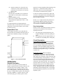
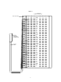
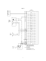
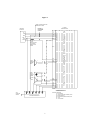
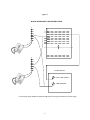
Power Connections Do not locate the control unit closer than 18 inches or further than five feet from the power supply. Do not use a lamp tester to check signals, use a voltmeter. A lamp tester when first applies is a short circuit to electronic circuits. Do not apply power to the control unit until all connections have been checked. Mounting The V-1109RTHF is designed to use -24VDC battery Connect the V/BR lead to Talk Ground Connect the BR/V lead to Talk Battery (-24VDC filtered). Connect the V/S lead to Signal Ground Connect the S/V lead to Signal Battery (-24VDC unfiltered) NOTE: When the V-1109RTHF is connected to a 1A2 Key System, connect W/O to 10VAC lamp battery. Refer to Figure 5 for connections. Mount the unit in a vacant space in an equipment cabinet, rack or key system cabinet, allowing enough room at the rear of the unit to plug in an amphenol connector. Mount a 66B type punchdown block near the unit and label it per Figure 2. NOTE: When the V-1109RTHF is connected to a Key System power supply, all grounds should be common and connect to an earth ground, i.e., cold water pipe. Cabling A 25 pair cable with a female connector should be ran from the unit to the connection block. The cable should be terminated on the connection block in standard color code order. Verify that the connections are correct prior to plugging the other end of the cable into the V-1109RTHF Page Unit. Speaker Connections The output for paging zones start at the BK/BR pair (zone 1) through the V/O pair (zone 9). Refer to Figure 4 for typical speaker connections using Valcom 45 Ohm Talkback speakers. No more than two 45 Ohm Talkback speakers may be connected to a zone. Connections to PABX System The V-1109RTHF may be accessed by connecting the W/BL and BL/W to the Tip and Ring, respectively, of a Loop Start Trunk Circuit. Refer to Figure 3 for connections. NOTE: All speakers should be connected with twisted pair, including cross-connections. Music Connections Connections to Electronic Key Systems The output of a tuner or receiver may be connected to the V/G pair of the V-1109RTHF to provide system-wide background music. The V-1109RTHF may be accessed by a C.O. line position of an Electronic Key System by connecting the W/BL, BL/W of the V-1109RTHF to a spare line position of the Electronic Key. This line position must be equipped with a trunk card. Refer to Figure 3 for connections. NOTE: A low level (0.25vrms) 8 to 600 Ohm source should be used. Do not connect the output of a high power amplifier to this input. Page and Music Level Set-up The V-1109RTHF has volume controls for the following functions: Speaker to phone Phone to speaker All Call master control Background music input control Zones 1-5 Background music input control Zones 6-9 Connections to 1A2 Key System The V-1109RTHF may be connected to a spare button of a 1A2 Key Telephone by making the following connections (a 400 type line card is not needed in this application): W/BL, BL/W of V-1109RTHF to spare button Tip and Ring. Refer to Figure 4 for connections. O/W to Lamp Lead of spare button for lamp connections. Refer to Figure 4 for connections. NOTE: For Meet Me Page on 1A2, connect A-Leads from spare button using 10K Ohm resistors in series with each A-Lead. The other side of resistors are connected to the BK/G (inhibit) of V-1109RTHF. Refer to Figure 6 for connections. Refer to Figure 7 for volume control locations. Control Set-Up: 1. Set-up Talkback Controls: (a) The phone to speaker level should be at a normal listening level. 3