1
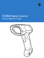
DS3508 Digital Scanner
Product Reference Guide
DS3508 Digital Scanner
Product Reference Guide
72E-124801-05
Revision A
March 2011
ii
DS3508 Product Reference Guide
© 2011 Motorola Solutions, Inc. All rights reserved.
No part of this publication may be reproduced or used in any form, or by any electrical or mechanical means, without permission in writing
from Motorola. This includes electronic or mechanical means, such as photocopying, recording, or information storage and retrieval
systems. The material in this manual is subject to change without notice.
The software is provided strictly on an “as is” basis. All software, including firmware, furnished to the user is on a licensed basis. Motorola
grants to the user a non-transferable and non-exclusive license to use each software or firmware program delivered hereunder (licensed
program). Except as noted below, such license may not be assigned, sublicensed, or otherwise transferred by the user without prior written
consent of Motorola. No right to copy a licensed program in whole or in part is granted, except as permitted under copyright law. The user
shall not modify, merge, or incorporate any form or portion of a licensed program with other program material, create a derivative work from
a licensed program, or use a licensed program in a network without written permission from Motorola. The user agrees to maintain
Motorola’s copyright notice on the licensed programs delivered hereunder, and to include the same on any authorized copies it makes, in
whole or in part. The user agrees not to decompile, disassemble, decode, or reverse engineer any licensed program delivered to the user
or any portion thereof.
Motorola reserves the right to make changes to any software or product to improve reliability, function, or design.
Motorola does not assume any product liability arising out of, or in connection with, the application or use of any product, circuit, or
application described herein.
No license is granted, either expressly or by implication, estoppel, or otherwise under any Motorola, Inc., intellectual property rights. An
implied license only exists for equipment, circuits, and subsystems contained in Motorola products.
MOTOROLA, MOTO, MOTOROLA SOLUTIONS and the Stylized M Logo are trademarks or registered trademarks of Motorola Trademark
Holding, LLC and are used under license. All other trademarks are the property of their respective owners.
This media, or Motorola Product, may include Motorola Software, Commercial Third Party Software, and Publicly Available Software.
The Motorola Software that may be included on this media, or included in the Motorola Product, is Copyright (c) by Motorola, Inc., and its
use is subject to the licenses, terms and conditions of the agreement in force between the purchaser of the Motorola Product and
Motorola, Inc.
The Commercial Third Party Software that may be included on this media, or included in the Motorola Product, is subject to the licenses,
terms and conditions of the agreement in force between the purchaser of the Motorola Product and Motorola, Inc., unless a separate
Commercial Third Party Software License is included, in which case, your use of the Commercial Third Party Software will then be
governed by the separate Commercial Third Party License.
The Publicly Available Software that may be included on this media, or in the Motorola Product, is listed below. The use of the listed
Publicly Available Software is subject to the licenses, terms and conditions of the agreement in force between the purchaser of the
Motorola Product and Motorola, Inc., as well as, the terms and conditions of the license of each Publicly Available Software package.
Copies of the licenses for the listed Publicly Available Software, as well as, all attributions, acknowledgements, and software information
details, are included below. Motorola is required to reproduce the software licenses, acknowledgments and copyright notices as provided
by the Authors and Owners, thus, all such information is provided in its native language form, without modification or translation.
The Publicly Available Software in the list below is limited to the Publicly Available Software included by Motorola. The Publicly Available
Software included by Commercial Third Party Software or Products, that is used in the Motorola Product, are disclosed in the Commercial
Third Party Licenses, or via the respective Commercial Third Party Publicly Available Software Legal Notices.
Publicly available software list:
Name:
Regular Expression Evaluator
Version:
8.3
Description:
Compiles and executes regular expressions
Software Site:
http://www.freebsd.org/cgi/cvsweb.cgi/src/lib/libc/regex/
Source Code:
No Source Distribution Obligations. Motorola will not provide nor distribute the Source Code for the
Regular Expression Evaluator.
License:
BSD Style License
© 1992 Henry Spencer.
© 1992, 1993 The Regents of the University of California. All rights reserved.
This code is derived from software contributed to Berkeley by Henry Spencer of the University of Toronto. Redistribution and use in source
and binary forms, with or without modification, are permitted provided that the following conditions are met:
1. Redistributions of source code must retain the above copyright notice, this list of conditions and the following disclaimer.
2. Redistributions in binary form must reproduce the above copyright notice, this list of conditions and the following disclaimer in the
documentation and/or other materials provided with the distribution.
iii
3. All advertising materials mentioning features or use of this software must display the following acknowledgement:
This product includes software developed by the University of California, Berkeley and its contributors.
4. Neither the name of the University nor the names of its contributors may be used to endorse or promote products derived from this
software without specific prior written permission.
THIS SOFTWARE IS PROVIDED BY THE REGENTS AND CONTRIBUTORS ``AS IS'' AND ANY EXPRESS OR IMPLIED
WARRANTIES, INCLUDING, BUT NOT LIMITED TO, THE IMPLIED WARRANTIES OF MERCHANTABILITY AND FITNESS FOR A
PARTICULAR PURPOSE ARE DISCLAIMED. IN NO EVENT SHALL THE REGENTS OR CONTRIBUTORS BE LIABLE FOR ANY
DIRECT, INDIRECT, INCIDENTAL, SPECIAL, EXEMPLARY, OR CONSEQUENTIAL DAMAGES (INCLUDING, BUT NOT LIMITED TO,
PROCUREMENT OF SUBSTITUTE GOODS OR SERVICES; LOSS OF USE, DATA, OR PROFITS; OR BUSINESS INTERRUPTION)
HOWEVER CAUSED AND ON ANY THEORY OF LIABILITY, WHETHER IN CONTRACT, STRICT LIABILITY, OR TORT (INCLUDING
NEGLIGENCE OR OTHERWISE) ARISING IN ANY WAY OUT OF THE USE OF THIS SOFTWARE, EVEN IF ADVISED OF THE
POSSIBILITY OF SUCH DAMAGE.
Motorola Solutions, Inc.
One Motorola Plaza
Holtsville, New York 11742-1300
http://www.motorola.com.
Warranty
For the complete Motorola Solutions hardware product warranty statement, go to:
http://www.motorola.com/enterprisemobility/warranty.
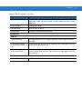
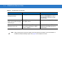
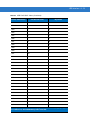
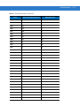
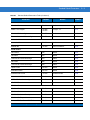
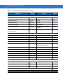
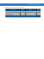
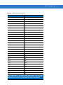
Revision History
Changes to the original manual are listed below:
Change
Date
Description
-01 Rev A
09/2009
Initial release.
-02 Rev A
11/2009
Update:
- Presentation Mode Field of View’ bar codes
- Supported baud rates for RS232.
-03 Rev A
02/2010
Add UID.
Update DPM information.
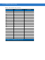
-04 Rev A
04/2010
Remove reference to Synapse (not supported); remove Regulatory information
as the complete Regulatory requirements appear in the Quick Start Guide;
update IEC definition in Glossary.
-05 Rev A
03/2011
Add: Decode Pager Motor Duration, Fuzzy 1D Processing, PDF Prioritization,
Prioritization Timeout, LCD Read Mode, CDC USB Com Port Emulation, Cute,
PDF417, Data Matrix, QR Codes, Aztec/Aztec Rune, Micro PDF, Maxicode,
Polling Interval, Quick Emulation, OCR, Coupon Report, Korean 3 of 5,
Australian Post Format, Databar Limited Security Level.
Update: Nixdorf Mode A and B columns, Inverse 1D defaults, Inverse Data Matrix
defaults.
Remove: Matrix 2 of 5 Redundancy.
iv
DS3508 Product Reference Guide
v
vi
DS3508 Product Reference Guide
Table of Contents
Warranty ........................................................................................................................ iii
Revision History ............................................................................................................. iii
About This Guide
Introduction ....................................................................................................................
Configurations................................................................................................................
Chapter Descriptions .....................................................................................................
Notational Conventions..................................................................................................
Related Documents .......................................................................................................
Service Information........................................................................................................
11
11
12
13
13
14
Chapter 1: Getting Started
Introduction ...................................................................................................................
Interfaces ......................................................................................................................
Unpacking .....................................................................................................................
Setting Up the Digital Scanner ......................................................................................
Installing the Interface Cable ..................................................................................
Removing the Interface Cable ................................................................................
Connecting Power (if required) ...............................................................................
Configuring the Digital Scanner ..............................................................................
Accessories ..................................................................................................................
Required Accessories .............................................................................................
Optional Accessories ..............................................................................................
1-1
1-2
1-2
1-3
1-3
1-4
1-4
1-4
1-5
1-5
1-5
Chapter 2: Scanning
Introduction ...................................................................................................................
Beeper Definitions ........................................................................................................
LED Definitions .............................................................................................................
Scanning .......................................................................................................................
Presentation Mode ..................................................................................................
Hand-Held Scanning ...............................................................................................
2-1
2-2
2-4
2-5
2-5
2-6
2
DS3508 Product Reference Guide
DS3508-SR/HD/DP Hand-Held Scanning ........................................................
Aiming .....................................................................................................................
Imager Aiming ...................................................................................................
Decode Ranges ............................................................................................................
2-6
2-6
2-6
2-8
Chapter 3: Maintenance & Technical Specifications
Introduction ...................................................................................................................
Maintenance .................................................................................................................
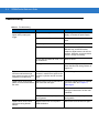
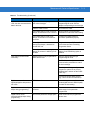
Troubleshooting ............................................................................................................
Technical Specifications ...............................................................................................
Digital Scanner Signal Descriptions ..............................................................................
3-1
3-1
3-2
3-5
3-7
Chapter 4: User Preferences & Miscellaneous Digital Scanner Options
Introduction ...................................................................................................................
Scanning Sequence Examples .....................................................................................
Errors While Scanning ..................................................................................................
User Preferences/Miscellaneous Options Parameter Defaults .....................................
User Preferences ..........................................................................................................
Set Default Parameter ............................................................................................
Parameter Bar Code Scanning ...............................................................................
Decode Pager Motor Enable ...................................................................................
Beep After Good Decode ........................................................................................
Beeper Volume .......................................................................................................
Beeper Tone ...........................................................................................................
Beeper Duration ......................................................................................................
Suppress Power-up Beeps .....................................................................................
Hands-Free Mode ...................................................................................................
Presentation Performance Mode ............................................................................
Digital Scanner Activity Modes ...............................................................................
Active Mode ......................................................................................................
Idle Mode ..........................................................................................................
Sleep Mode .......................................................................................................
Low Power Mode ..............................................................................................
Time Delay to Presentation Idle Mode ..............................................................
Time Delay to Presentation Sleep Mode ..........................................................
Low Power Mode ..............................................................................................
Time Delay to Low Power Mode .......................................................................
Trigger Mode ...........................................................................................................
Fuzzy 1D Processing ..............................................................................................
Picklist Mode ...........................................................................................................
PDF Prioritization ....................................................................................................
PDF Prioritization Timeout ......................................................................................
DPM Scanning ........................................................................................................
Continuous Bar Code Read ....................................................................................
Decode Session Timeout ........................................................................................
Timeout Between Decodes, Same Symbol ............................................................
Timeout Between Decodes, Different Symbols ......................................................
Hand-Held Decode Aiming Pattern .........................................................................
4-1
4-2
4-2
4-2
4-5
4-5
4-6
4-7
4-9
4-9
4-10
4-11
4-11
4-12
4-12
4-12
4-13
4-13
4-13
4-13
4-14
4-16
4-18
4-19
4-21
4-22
4-23
4-24
4-25
4-26
4-27
4-27
4-28
4-28
4-29
Table of Contents
Hands-Free Decode Aiming Pattern .......................................................................
Presentation Mode Field of View ............................................................................
LCD Read Mode .....................................................................................................
Decoding Illumination (Hand-Held Mode only) .......................................................
Multicode Mode .......................................................................................................
Multicode Expression ..............................................................................................
Multicode Expression Syntax ............................................................................
Notes .................................................................................................................
Multicode Mode Concatenation ..............................................................................
Multicode Concatenation Symbology ......................................................................
Multicode Troubleshooting ......................................................................................
Troubleshooting Multicode Expression Programming ......................................
Troubleshooting Multicode Mode Scanning and Decoding ...............................
Miscellaneous Scanner Parameters .............................................................................
Transmit Code ID Character ...................................................................................
Prefix/Suffix Values .................................................................................................
Scan Data Transmission Format ............................................................................
FN1 Substitution Values .........................................................................................
Scan Data Transmission Format (continued) .........................................................
Transmit “No Read” Message .................................................................................
UID Parsing .............................................................................................................
UID Parsing Output ...........................................................................................
UID Error Mode Options ...................................................................................
Sample ADF Rule for UID .................................................................................
UID Sample Bar Codes .....................................................................................
4-30
4-31
4-32
4-33
4-34
4-35
4-35
4-36
4-40
4-41
4-42
4-42
4-42
4-44
4-44
4-45
4-46
4-47
4-47
4-48
4-49
4-50
4-51
4-52
4-53
Chapter 5: Imaging Preferences
Introduction ...................................................................................................................
Scanning Sequence Examples .....................................................................................
Errors While Scanning ..................................................................................................
Imaging Preferences Parameter Defaults .....................................................................
Imaging Preferences .....................................................................................................
Operational Modes ..................................................................................................
Decode Mode ....................................................................................................
Snapshot Mode .................................................................................................
Image Capture Illumination .....................................................................................
Gain/Exposure Priority for Snapshot Mode .............................................................
Snapshot Mode Timeout .........................................................................................
Snapshot Aiming Pattern ........................................................................................
Image Cropping ......................................................................................................
Crop to Pixel Addresses .........................................................................................
Image Size (Number of Pixels) ...............................................................................
Image Brightness (Target White) ............................................................................
JPEG Image Options ..............................................................................................
JPEG Target File Size ............................................................................................
JPEG Quality and Size Value .................................................................................
Image Enhancement ...............................................................................................
Image File Format Selector .....................................................................................
Bits Per Pixel ...........................................................................................................
5-1
5-2
5-2
5-2
5-4
5-4
5-4
5-4
5-5
5-6
5-7
5-7
5-8
5-9
5-10
5-11
5-11
5-12
5-12
5-13
5-14
5-15
3
4
DS3508 Product Reference Guide
Signature Capture ...................................................................................................
Output File Format ............................................................................................
Signature Capture File Format Selector .................................................................
Signature Capture Bits Per Pixel ............................................................................
Signature Capture Width .........................................................................................
Signature Capture Height .......................................................................................
Signature Capture JPEG Quality ............................................................................
Video View Finder ...................................................................................................
Video View Finder Image Size ................................................................................
5-16
5-16
5-17
5-18
5-19
5-19
5-19
5-20
5-20
Chapter 6: USB Interface
Introduction ...................................................................................................................
Connecting a USB Interface .........................................................................................
USB Parameter Defaults ..............................................................................................
USB Host Parameters ..................................................................................................
USB Device Type ....................................................................................................
................................................................................................................................
Symbol Native API (SNAPI) Status Handshaking ...................................................
USB Country Keyboard Types - Country Codes .....................................................
USB Keystroke Delay .............................................................................................
USB CAPS Lock Override ......................................................................................
USB Ignore Unknown Characters ...........................................................................
Emulate Keypad ......................................................................................................
Emulate Keypad with Leading Zero ........................................................................
USB Keyboard FN 1 Substitution ............................................................................
Function Key Mapping ............................................................................................
Simulated Caps Lock ..............................................................................................
Convert Case ..........................................................................................................
USB Static CDC ......................................................................................................
USB Polling Interval ................................................................................................
Quick Keypad Emulation .........................................................................................
ASCII Character Set for USB ........................................................................................
6-1
6-2
6-3
6-4
6-4
6-5
6-5
6-6
6-8
6-8
6-9
6-9
6-10
6-10
6-11
6-11
6-12
6-12
6-13
6-15
6-16
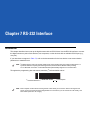
Chapter 7: RS-232 Interface
Introduction ...................................................................................................................
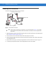
Connecting an RS-232 Interface ..................................................................................
RS-232 Parameter Defaults ..........................................................................................
RS-232 Host Parameters ..............................................................................................
RS-232 Host Types .................................................................................................
Baud Rate ...............................................................................................................
Parity .......................................................................................................................
Data Bits .................................................................................................................
Stop Bit Select ........................................................................................................
Check Receive Errors .............................................................................................
Hardware Handshaking ..........................................................................................
Software Handshaking ............................................................................................
Host Serial Response Time-out ..............................................................................
RTS Line State ........................................................................................................
7-1
7-2
7-3
7-4
7-6
7-8
7-9
7-9
7-10
7-10
7-11
7-13
7-15
7-16
Table of Contents
Beep on <BEL> .......................................................................................................
Intercharacter Delay ................................................................................................
Nixdorf Beep/LED Options ......................................................................................
Ignore Unknown Characters ...................................................................................
ASCII Character Set for RS-232 ...................................................................................
7-16
7-17
7-18
7-18
7-19
Chapter 8: IBM 468X / 469X Interface
Introduction ...................................................................................................................
Connecting to an IBM 468X/469X Host ........................................................................
IBM Parameter Defaults ...............................................................................................
IBM 468X/469X Host Parameters .................................................................................
Port Address ...........................................................................................................
Convert Unknown to Code 39 .................................................................................
8-1
8-2
8-3
8-4
8-4
8-5
Chapter 9: Keyboard Wedge Interface
Introduction ...................................................................................................................
Connecting a Keyboard Wedge Interface .....................................................................
Keyboard Wedge Parameter Defaults ..........................................................................
Keyboard Wedge Host Parameters ..............................................................................
Keyboard Wedge Host Types .................................................................................
Keyboard Wedge Country Types - Country Codes .................................................
Ignore Unknown Characters ...................................................................................
Keystroke Delay ......................................................................................................
Intra-Keystroke Delay .............................................................................................
Alternate Numeric Keypad Emulation .....................................................................
Caps Lock On .........................................................................................................
Caps Lock Override ................................................................................................
Convert Wedge Data ..............................................................................................
Function Key Mapping ............................................................................................
FN1 Substitution .....................................................................................................
Send Make and Break ............................................................................................
Keyboard Maps .......................................................................................................
ASCII Character Set for Keyboard Wedge ...................................................................
Introduction ...................................................................................................................
9-1
9-2
9-3
9-4
9-4
9-5
9-7
9-7
9-8
9-8
9-9
9-9
9-10
9-10
9-11
9-11
9-12
9-13
10-1
Chapter 10: OCR Programming
OCR Parameter Defaults ..............................................................................................
OCR Programming Parameters ....................................................................................
Enable/Disable OCR-A ...........................................................................................
OCR-A Variant ........................................................................................................
Enable/Disable OCR-B ...........................................................................................
OCR-B Variant ........................................................................................................
Enable/Disable MICR E13B ....................................................................................
Enable/Disable US Currency Serial Number ..........................................................
OCR Orientation .....................................................................................................
OCR Lines ..............................................................................................................
OCR Minimum Characters ......................................................................................
10-2
10-3
10-3
10-3
10-5
10-6
10-9
10-10
10-10
10-12
10-12
5
6
DS3508 Product Reference Guide
OCR Maximum Characters .....................................................................................
OCR Security Level ................................................................................................
OCR Subset ............................................................................................................
OCR Quiet Zone .....................................................................................................
OCR Bright Illumination ..........................................................................................
OCR Template ........................................................................................................
Required Digit (9) .............................................................................................
Required Alpha (A) ..........................................................................................
Optional Alphanumeric (1) ...............................................................................
Optional Alpha (2) ............................................................................................
Alpha or Digit (3) ..............................................................................................
Any Including Space & Reject (4) ....................................................................
Any except Space & Reject (5) ........................................................................
Optional Digit (7) ..............................................................................................
Digit or Fill (8) ...................................................................................................
Alpha or Fill (F) ................................................................................................
Optional Space ( ) ............................................................................................
Optional Small Special (.) ................................................................................
Other Template Operators ................................................................................
Repeat Previous (R) .........................................................................................
Template Examples ..........................................................................................
OCR Check Digit Modulus ......................................................................................
OCR Check Digit Multiplier .....................................................................................
OCR Check Digit Validation ....................................................................................
None .................................................................................................................
Product Add Left to Right ..................................................................................
Product Add Right to Left ..................................................................................
Digit Add Left to Right .......................................................................................
Digit Add Right to Left .......................................................................................
Product Add Right to Left Simple Remainder ...................................................
Digit Add Right To Left Simple Remainder .......................................................
Health Industry - HIBCC43 ...............................................................................
10-13
10-13
10-14
10-14
10-15
10-16
10-16
10-16
10-17
10-17
10-17
10-18
10-18
10-18
10-19
10-19
10-19
10-20
10-20
10-24
10-25
10-25
10-26
10-27
10-27
10-27
10-28
10-28
10-29
10-30
10-31
10-31
Chapter 11: Symbologies
Introduction ...................................................................................................................
Scanning Sequence Examples .....................................................................................
Errors While Scanning ..................................................................................................
Symbology Parameter Defaults ....................................................................................
UPC/EAN ......................................................................................................................
Enable/Disable UPC-A ............................................................................................
Enable/Disable UPC-E ............................................................................................
Enable/Disable UPC-E1 ..........................................................................................
Enable/Disable EAN-8/JAN-8 .................................................................................
Enable/Disable EAN-13/JAN-13 .............................................................................
Enable/Disable Bookland EAN ...............................................................................
Decode UPC/EAN/JAN Supplementals ..................................................................
User-Programmable Supplementals .......................................................................
UPC/EAN/JAN Supplemental Redundancy ............................................................
UPC/EAN/JAN Supplemental AIM ID Format .........................................................
11-1
11-1
11-2
11-2
11-7
11-7
11-7
11-8
11-8
11-9
11-9
11-10
11-13
11-13
11-14
Table of Contents
Transmit UPC-A Check Digit ..................................................................................
Transmit UPC-E Check Digit ..................................................................................
Transmit UPC-E1 Check Digit ................................................................................
UPC-A Preamble ....................................................................................................
UPC-E Preamble ....................................................................................................
UPC-E1 Preamble ..................................................................................................
Convert UPC-E to UPC-A .......................................................................................
Convert UPC-E1 to UPC-A .....................................................................................
EAN-8/JAN-8 Extend ..............................................................................................
Bookland ISBN Format ...........................................................................................
UCC Coupon Extended Code .................................................................................
Coupon Report ........................................................................................................
ISSN EAN ...............................................................................................................
Code 128 ......................................................................................................................
Enable/Disable Code 128 .......................................................................................
Set Lengths for Code 128 .......................................................................................
Enable/Disable GS1-128 (formerly UCC/EAN-128) ................................................
Enable/Disable ISBT 128 ........................................................................................
ISBT Concatenation ................................................................................................
Check ISBT Table ...................................................................................................
ISBT Concatenation Redundancy ...........................................................................
Code 39 ........................................................................................................................
Enable/Disable Code 39 .........................................................................................
Enable/Disable Trioptic Code 39 ............................................................................
Convert Code 39 to Code 32 ..................................................................................
Code 32 Prefix ........................................................................................................
Set Lengths for Code 39 .........................................................................................
Code 39 Check Digit Verification ............................................................................
Transmit Code 39 Check Digit ................................................................................
Code 39 Full ASCII Conversion ..............................................................................
Code 39 Buffering - Scan & Store ...........................................................................
Buffer Data ........................................................................................................
Clear Transmission Buffer ................................................................................
Transmit Buffer .................................................................................................
Overfilling Transmission Buffer .........................................................................
Attempt to Transmit an Empty Buffer ................................................................
Code 93 ........................................................................................................................
Enable/Disable Code 93 .........................................................................................
Set Lengths for Code 93 .........................................................................................
Code 11 ........................................................................................................................
Set Lengths for Code 11 .........................................................................................
Code 11 Check Digit Verification ............................................................................
Transmit Code 11 Check Digits ..............................................................................
Interleaved 2 of 5 (ITF) .................................................................................................
Enable/Disable Interleaved 2 of 5 ...........................................................................
Set Lengths for Interleaved 2 of 5 ...........................................................................
I 2 of 5 Check Digit Verification ...............................................................................
Transmit I 2 of 5 Check Digit ...................................................................................
Convert I 2 of 5 to EAN-13 ......................................................................................
Discrete 2 of 5 (DTF) ....................................................................................................
11-14
11-15
11-15
11-16
11-17
11-18
11-19
11-19
11-20
11-21
11-22
11-23
11-24
11-25
11-25
11-25
11-26
11-27
11-28
11-29
11-29
11-30
11-30
11-30
11-31
11-31
11-32
11-33
11-33
11-34
11-34
11-35
11-35
11-36
11-36
11-36
11-37
11-37
11-37
11-39
11-39
11-41
11-42
11-42
11-42
11-43
11-45
11-45
11-46
11-46
7
8
DS3508 Product Reference Guide
Enable/Disable Discrete 2 of 5 ................................................................................
Set Lengths for Discrete 2 of 5 ...............................................................................
Codabar (NW - 7) .........................................................................................................
Enable/Disable Codabar .........................................................................................
Set Lengths for Codabar .........................................................................................
CLSI Editing ............................................................................................................
NOTIS Editing .........................................................................................................
MSI ...............................................................................................................................
Enable/Disable MSI ................................................................................................
Set Lengths for MSI ................................................................................................
MSI Check Digits ....................................................................................................
Transmit MSI Check Digit(s) ...................................................................................
MSI Check Digit Algorithm ......................................................................................
Chinese 2 of 5 ...............................................................................................................
Enable/Disable Chinese 2 of 5 ................................................................................
Matrix 2 of 5 ..................................................................................................................
Enable/Disable Matrix 2 of 5 ...................................................................................
Set Lengths for Matrix 2 of 5 ...................................................................................
Matrix 2 of 5 Check Digit .........................................................................................
Transmit Matrix 2 of 5 Check Digit ..........................................................................
Korean 3 of 5 ................................................................................................................
Enable/Disable Korean 3 of 5 .................................................................................
Inverse 1D ....................................................................................................................
Postal Codes ................................................................................................................
US Postnet ..............................................................................................................
US Planet ................................................................................................................
Transmit US Postal Check Digit ..............................................................................
UK Postal ................................................................................................................
Transmit UK Postal Check Digit ..............................................................................
Japan Postal ...........................................................................................................
Australian Postal .....................................................................................................
Australia Post Format .............................................................................................
Netherlands KIX Code ...........................................................................................
USPS 4CB/One Code/Intelligent Mail .....................................................................
UPU FICS Postal ....................................................................................................
GS1 DataBar ................................................................................................................
GS1 DataBar-14 .....................................................................................................
GS1 DataBar Limited ..............................................................................................
GS1 DataBar Limited Security Level ......................................................................
GS1 DataBar Expanded .........................................................................................
Convert GS1 DataBar to UPC/EAN ........................................................................
Composite .....................................................................................................................
Composite CC-C .....................................................................................................
Composite CC-A/B ..................................................................................................
Composite TLC-39 ..................................................................................................
UPC Composite Mode ............................................................................................
Composite Beep Mode ...........................................................................................
GS1-128 Emulation Mode for UCC/EAN Composite Codes ...................................
2D Symbologies ............................................................................................................
Enable/Disable PDF417 ..........................................................................................
11-46
11-47
11-49
11-49
11-49
11-51
11-51
11-52
11-52
11-52
11-54
11-54
11-55
11-55
11-55
11-56
11-56
11-57
11-58
11-58
11-59
11-59
11-60
11-61
11-61
11-61
11-62
11-62
11-63
11-63
11-64
11-65
11-66
11-66
11-66
11-68
11-68
11-68
11-69
11-70
11-70
11-71
11-71
11-71
11-72
11-72
11-73
11-73
11-74
11-74
Table of Contents
Enable/Disable MicroPDF417 .................................................................................
Code 128 Emulation ...............................................................................................
Data Matrix ..............................................................................................................
Data Matrix Inverse .................................................................................................
Maxicode .................................................................................................................
QR Code .................................................................................................................
QR Inverse ..............................................................................................................
MicroQR ..................................................................................................................
Aztec .......................................................................................................................
Aztec Inverse ..........................................................................................................
Redundancy Level ........................................................................................................
Redundancy Level 1 ...............................................................................................
Redundancy Level 2 ...............................................................................................
Redundancy Level 3 ...............................................................................................
Redundancy Level 4 ...............................................................................................
Security Level ...............................................................................................................
Intercharacter Gap Size ..........................................................................................
Report Version ..............................................................................................................
Macro PDF Features ....................................................................................................
Flush Macro Buffer ..................................................................................................
Abort Macro PDF Entry ...........................................................................................
Chapter 12: 123Scan2
Introduction ...................................................................................................................
Communication with 123Scan2 ....................................................................................
123Scan2 Requirements ..............................................................................................
More Information ...........................................................................................................
11-74
11-75
11-76
11-77
11-78
11-78
11-79
11-79
11-80
11-80
11-81
11-81
11-81
11-81
11-82
11-83
11-84
11-84
11-85
11-85
11-85
12-1
12-1
12-1
12-1
Chapter 13: Advanced Data Formatting
Introduction ................................................................................................................... 13-1
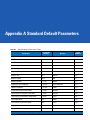
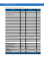
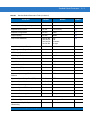
Appendix A: Standard Default Parameters
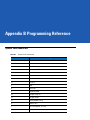
Appendix B: Programming Reference
Symbol Code Identifiers ................................................................................................ B-1
AIM Code Identifiers ..................................................................................................... B-3
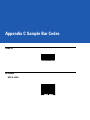
Appendix C: Sample Bar Codes
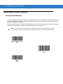
Code 39 ........................................................................................................................
UPC/EAN ......................................................................................................................
UPC-A, 100% ..........................................................................................................
EAN-13, 100% ........................................................................................................
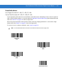
Code 128 ......................................................................................................................
Interleaved 2 of 5 ..........................................................................................................
GS1 DataBar-14 ...........................................................................................................
C-1
C-1
C-1
C-2
C-2
C-2
C-3
9
10
DS3508 Product Reference Guide
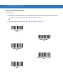
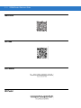
PDF417 .........................................................................................................................
Data Matrix ...................................................................................................................
Maxicode ......................................................................................................................
QR Code .......................................................................................................................
US Postnet ....................................................................................................................
UK Postal ......................................................................................................................
C-3
C-3
C-4
C-4
C-4
C-4
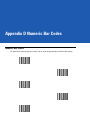
Appendix D: Numeric Bar Codes
Numeric Bar Codes ...................................................................................................... D-1
Cancel ........................................................................................................................... D-2
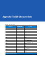
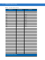
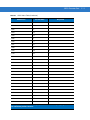
Appendix E: ASCII Character Sets
Appendix F: Signature Capture Code
Introduction ...................................................................................................................
Code Structure ..............................................................................................................
Signature Capture Area ..........................................................................................
CapCode Pattern Structure .....................................................................................
Start / Stop Patterns .....................................................................................................
Dimensions ...................................................................................................................
Data Format ..................................................................................................................
Additional Capabilities ..................................................................................................
Signature Boxes ...........................................................................................................
Glossary
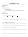
Tell Us What You Think...
F-1
F-1
F-1
F-2
F-2
F-3
F-3
F-4
F-4
About This Guide
Introduction
The DS3508 Product Reference Guide provides general instructions for setting up, operating, maintaining, and
troubleshooting the DS3508 digital scanner.
Configurations
This guide includes the following configurations:
• DS3508-SR20005R – DS3508 digital scanner, standard range
• DS3508-HD20005R – DS3508 digital scanner, high density focus
• DS3508-DP20005R – DS3508 digital scanner, DPM.
12
DS3508 Product Reference Guide
Chapter Descriptions
Topics covered in this guide are as follows:
• Chapter 1, Getting Started provides a product overview, unpacking instructions, and cable connection
information.
• Chapter 2, Scanning describes parts of the digital scanner, beeper and LED definitions, and how to use the
scanner in hand-held and hands-free (presentation) modes.
• Chapter 3, Maintenance & Technical Specifications provides information on how to care for the digital
scanner, troubleshooting, and technical specifications.
• Chapter 4, User Preferences & Miscellaneous Digital Scanner Options describes features frequently used to
customize how data transmits to the host device and programming bar codes for selecting user preference
features for the digital scanner.
• Chapter 5, Imaging Preferences provides imaging preference features and programming bar codes for
selecting these features.
• Chapter 6, USB Interface describes how to set up the digital scanner with a USB host.
• Chapter 7, RS-232 Interface describes how to set up the digital scanner with an RS-232 host, such as
point-of-sale devices, host computers, or other devices with an available RS-232 port.
• Chapter 8, IBM 468X / 469X Interface describes how to set up the digital scanner with IBM 468X/469X POS
systems.
• Chapter 9, Keyboard Wedge Interface describes how to set up a Keyboard Wedge interface with the digital
scanner.
• Chapter 10, OCR Programming describes how to set up the digital scanner for OCR programming.
• Chapter 11, Symbologies describes all symbology features and provides programming bar codes for
selecting these features for the digital scanner.
• Chapter 12, 123Scan2 (PC based scanner configuration tool) enables rapid and easy customized setup of
Motorola Scanners.
• Chapter 13, Advanced Data Formatting briefly describes ADF, a means of customizing data before
transmission to the host device, and includes a reference to the ADF Programmer Guide.
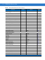
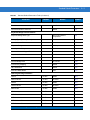
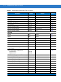
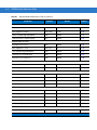
• Appendix A, Standard Default Parameters provides a table of all host devices and miscellaneous scanner
defaults.
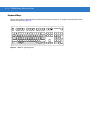
• Appendix B, Programming Reference provides a table of AIM code identifiers, ASCII character conversions,
and keyboard maps.
• Appendix C, Sample Bar Codes includes sample bar codes of various code types.
• Appendix D, Numeric Bar Codes includes the numeric bar codes to scan for parameters requiring specific
numeric values.
• Appendix E, ASCII Character Sets provides ASCII character value tables.
• Appendix F, Signature Capture Code provides information on CapCode, a signature capture code that
encloses a signature area on a document and allows a scanner to capture a signature.
About This Guide
13
Notational Conventions
The following conventions are used in this document:
• Italics are used to highlight the following:
• Chapters and sections in this and related documents
• Dialog box, window and screen names
• Drop-down list and list box names
• Check box and radio button names
• Bold text is used to highlight the following:
• Key names on a keypad
• Button names on a screen.
• bullets (•) indicate:
• Action items
• Lists of alternatives
• Lists of required steps that are not necessarily sequential
• Sequential lists (e.g., those that describe step-by-step procedures) appear as numbered lists.
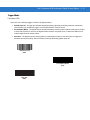
• Throughout the programming bar code menus, asterisks (*) are used to denote default parameter settings.
* Indicates Default
*Baud Rate 9600
Feature/Option
Related Documents
• DS3508 Quick Start Guide, p/n 72-124802-xx - provides general information for getting started with the
DS3508 digital scanner, and includes basic set up and operation instructions.
For the latest version of all guides, go to: http:supportcentral.motorola.com.
14
DS3508 Product Reference Guide
Service Information
If you have a problem with your equipment, contact Motorola Enterprise Mobility support for your region. Contact
information is available at: http://www.motorola.com/enterprisemobilitysupport.
When contacting Enterprise Mobility support, please have the following information available:
• Serial number of the unit
• Model number or product name
• Software type and version number
Motorola responds to calls by e-mail, telephone or fax within the time limits set forth in service agreements.
If your problem cannot be solved by Motorola Enterprise Mobility Support, you may need to return your equipment
for servicing and will be given specific directions. Motorola is not responsible for any damages incurred during
shipment if the approved shipping container is not used. Shipping the units improperly can possibly void the
warranty.
If you purchased your Enterprise Mobility business product from a Motorola business partner, please contact that
business partner for support.
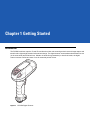
Chapter 1 Getting Started
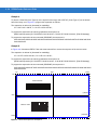
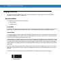
Introduction
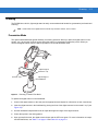
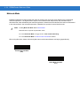
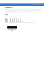
The DS3508 combines superior 1D and 2D omnidirectional bar code scanning and sub-second image capture and
transfer with a light-weight, hands-free/hand-held design. The digital scanner accommodates both hands-free use
(in the scan stand) and hand-held use. Whether in hands-free (presentation) or hand-held mode, the digital
scanner ensures comfort and ease of use for extended periods of time.
Figure 1-1 DS3508 Digital Scanner
1-2
DS3508 Product Reference Guide
Interfaces
The DS3508 digital scanner supports:
• USB connection to a host. The digital scanner autodetects a USB host and defaults to the HID keyboard
interface type. Select other USB interface types by scanning programming bar code menus.This interface
supports the following international keyboards (for Windows® environment): North America, German,
French, French Canadian, Spanish, Italian, Swedish, UK English, Portuguese-Brazilian, and Japanese.
• Standard RS-232 connection to a host. Scan bar code menus to set up communication of the digital scanner
with the host.
• Connection to IBM 468X/469X hosts. Scan bar code menus to set up communication of the digital scanner
with the IBM terminal.
• Keyboard Wedge connection to a host. The host interprets scanned data as keystrokes. Scan bar code
menus to set up communication of the digital scanner with the host. This interface supports the following
international keyboards (for Windows® environment): North America, German, French, French Canadian,
French Belgian, Spanish, Italian, Swedish, UK English, Portuguese-Brazilian, and Japanese.
Unpacking
Remove the digital scanner from its packing and inspect it for damage. If the scanner was damaged in transit,
contact Motorola Enterprise Mobility Support. See page 14 for contact information. KEEP THE PACKING. It is the
approved shipping container; use this to return the equipment for servicing.
Getting Started
1-3
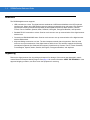
Setting Up the Digital Scanner
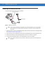
Installing the Interface Cable
NOTE
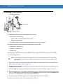
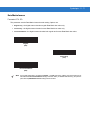
1.
Different hosts require different cables. The connectors illustrated in each host chapter are examples only.
Connectors vary from those illustrated, but the steps to connect the digital scanner are the same.
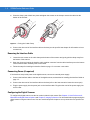
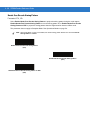
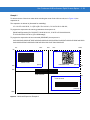
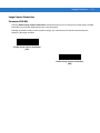
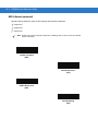
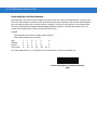
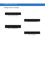
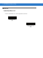
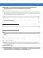
Loosen the two screws on the cable clamp at the bottom of the scanner and gently pull the clamp away from
the bottom of the scanner.
Figure 1-2 Removing the Cable Clamp
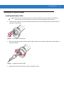
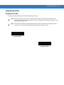
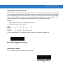
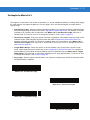
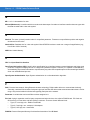
2.
Open the clamp and plug the interface cable modular connector into the cable interface port on the bottom of
the scanner handle.
Figure 1-3 Inserting the Interface Cable
3.
Gently tug the cable to ensure the connector is properly secured.
1-4
DS3508 Product Reference Guide
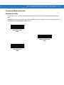
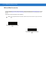
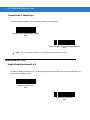
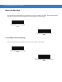
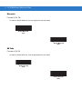
4.
Close the clamp, push it back into place and tighten the screws on the clamp to secure the cable into the
bottom of the scanner.
Figure 1-4 Closing the Cable Clamp
5.
Connect the other end of the interface cable to the host (see the specific host chapter for information on host
connections).
Removing the Interface Cable
1.
Loosen the two screws on the cable clamp at the bottom of the scanner and gently pull the clamp away from
the bottom of the scanner.
2.
Open the clamp and unplug the interface cable modular connector from the cable interface port on the bottom
of the scanner handle. Carefully slide out the cable.
3.
Follow the steps for Installing the Interface Cable on page 1-3 to connect a new cable.
Connecting Power (if required)
If the host does not provide power to the digital scanner, connect an external power supply:
1.
Connect the interface cable to the base of the digital scanner, as described in Installing the Interface Cable on
page 1-3.
2.
Connect the other end of the interface cable to the host (refer to the host manual to locate the correct port).
3.
Plug the power supply into the power jack on the interface cable. Plug the other end of the power supply into
an AC outlet.
Configuring the Digital Scanner
To configure the digital scanner use the bar codes included in this manual. See Chapter 4, User Preferences &
Miscellaneous Digital Scanner Options and Chapter 5, Imaging Preferences for information about programming the
digital scanner using bar code menus. Also see each host-specific chapter to set up connection to a specific host
type.
Getting Started
1-5
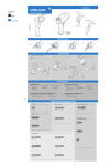
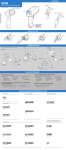
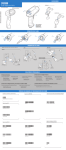
Accessories
Required Accessories
The digital scanner requires an interface cable and may require a power supply. These items can be purchased
from Motorola.
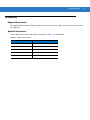
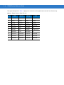
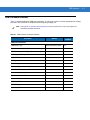
Optional Accessories
Contact Motorola to purchase the optional accessories inTable 1-1 for the DS3508.
Table 1-1 Optional Accessories
Accessory
Part Number
Scanner Belt Holster
11-35035-01R
Intellistand for DS3508
20-54090-07R (see page 2-5).
Desk Top Holder
20-67176-01R
Multi-Mount Stand
12-44267-01R
Tool Balancer
50-15400-03
1-6
DS3508 Product Reference Guide
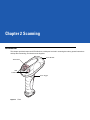
Chapter 2 Scanning
Introduction
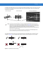
This chapter provides beeper and LED definitions, techniques involved in scanning bar codes, general instructions
and tips about scanning, and decode zone diagrams.
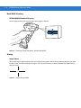
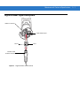
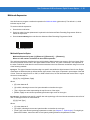
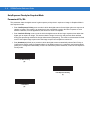
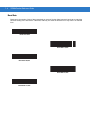
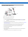
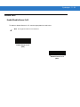
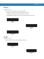
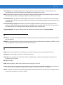
Scan Window
Tether Plate
LED
Indicators
Scan Trigger
Figure 2-1 Parts
2-2
DS3508 Product Reference Guide
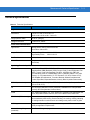
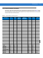
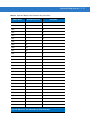
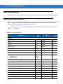
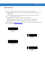
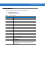
Beeper Definitions
The digital scanner issues different beep sequences and patterns to indicate status. Table 2-1 defines beep
sequences that occur during both normal scanning and while programming the digital scanner.
Table 2-1 Beeper Definitions
Beeper Sequence
Indication
Standard Use
Low/medium/high beeps
Power up.
Short high beep
A bar code symbol was decoded (if decode beeper is enabled).
4 long low beeps
Transmission error.
5 low beeps
Conversion or format error.
Low/low/low/extra low beeps
RS-232 receive error.
High beep
The digital scanner detected a <BEL> character over RS-232.
Image Capture
Low beep
Snapshot mode started or completed.
High/low beeps
Snapshot mode timed out.
Parameter Menu Scanning
Low/high beeps
Input error; incorrect bar code, programming sequence, or Cancel scanned.
High/low beeps
Keyboard parameter selected. Enter value using numeric bar codes.
High/low/high/low beeps
Successful program exit with change in parameter setting.
Code 39 Buffering
High/low beeps
New Code 39 data was entered into the buffer.
3 long high beeps
Code 39 buffer is full.
High/low/high beeps
The Code 39 buffer was erased.
Low/high/low beeps
The Code 39 buffer was erased or there was an attempt to clear or transmit an
empty buffer.
Low/high beeps
A successful transmission of buffered data.
Macro PDF
2 low beeps
MPDF sequence buffered.
2 long low beeps
File ID error. A bar code not in the current MPDF sequence was scanned.
3 long low beeps
Out of memory. There is not enough buffer space to store the current MPDF
symbol.
Scanning
2-3
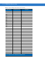
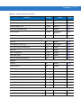
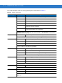
Table 2-1 Beeper Definitions (Continued)
Beeper Sequence
Indication
4 long low beeps
Bad symbology. Scanned a 1D or 2D bar code in a MPDF sequence, a duplicate
MPDF label, a label in an incorrect order, or trying to transmit an empty or illegal
MPDF field.
5 long low beeps
Flushing MPDF buffer.
Fast warble beep
Aborting MPDF sequence.
Low/high beeps
Flushing an already empty MPDF buffer.
Host Specific
USB only
4 short high beeps
The digital scanner has not completed initialization. Wait several seconds and
scan again.
Low/medium/high beeps
upon scanning a USB device
type
Communication with the host must be established before the digital scanner can
operate at the highest power level.
Low/medium/high beeps
occur more than once
The USB host can put the digital scanner in a state where power to the scanner is
cycled on and off more than once. This is normal and usually happens when the
PC cold boots.
RS-232 only
1 short high beep
A <BEL> character is received and Beep on <BEL> is enabled.
2-4
DS3508 Product Reference Guide
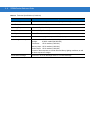
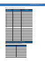
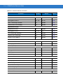
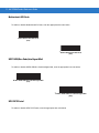
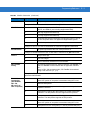
LED Definitions
In addition to beep sequences, the digital scanner uses a two-color LED to indicate status. Table 2-2 defines LED
colors that display during scanning.
Table 2-2 Standard LED Definitions
LED
Indication
Hand-Held Scanning Standard Use
Green
A bar code was successfully decoded.
Red
Transmission error, conversion or format error, or RS-232 receive error.
Off
No power is applied to the digital scanner, or the scanner is on and ready to scan.
Presentation (Hands-Free) Scanning Standard Use
Green
The scanner is on and ready to scan.
Momentarily Off
A bar code was successfully decoded.
Red
Transmission error, conversion or format error, or RS-232 receive error.
Off
No power is applied to the digital scanner, or the scanner is in low power mode.
Parameter Programming
Green
Number expected. Enter value using numeric bar codes.
Successful program exit with change in parameter setting.
Red
Input error: incorrect bar code, programming sequence, or Cancel scanned.
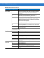
ADF Programming
Green
Enter another digit. Add leading zeros to the front if necessary.
Enter another alphabetic character or scan the End of Message bar code.
All criteria or actions cleared for current rule, continue entering rule.
Delete last saved rule. The current rule is left intact.
All rules deleted.
Blinking Green
Enter another criterion or action, or scan the Save Rule bar code.
Green after Blinking
Rule saved. Rule entry mode exited.
Cancel rule entry. Rule entry mode exited because of an error or the user asked to exit
rule entry.
Red
Out of rule memory. Erase some existing rules, then try to save rule again.
Entry error, wrong bar code scanned, or criteria/action list is too long for a rule. Re-enter
criterion or action.
Scanning
2-5
Scanning
The DS3508 has a built-in, light-weight stand to easily accommodate both hands-free (presentation) and hand-held
scanning.
NOTE
Certain areas of the digital scanner’s handle may feel warm at times. This is normal.
Presentation Mode
The optional Intellistand adds greater flexibility to scanning operation. When you place the digital scanner in the
stand’s “cup,” the scanner’s built-in sensor places the scanner in presentation (hands-free) mode. When you
remove the digital scanner from the stand it operates in its normal hand-held mode.
Adjust angle of
scanner “cup”
Scanner “Cup”
Adjust height of
IntelliStand
Figure 2-2 Scanning in Hands-Free Mode
To operate the digital scanner in the Intellistand:
1.
Connect the digital scanner to the host (see the appropriate host chapter for information on host connections).
2.
Insert the digital scanner in the Intellistand by placing the front of the digital scanner into the stand’s “cup” (see
Figure 2-2).
3.
Use the Intellistand’s adjustment knobs to adjust the height and angle of the digital scanner.
4.
Center the symbol in the aiming pattern.
5.
Upon successful decode, the digital scanner beeps and the LED turns green. For more information on beeper
and LED definitions, see Table 2-1 on page 2-2 and Table 2-2 on page 2-4.
2-6
DS3508 Product Reference Guide
Hand-Held Scanning
DS3508-SR/HD/DP Hand-Held Scanning
Aim the digital scanner at a bar code and pull the trigger to decode.
Figure 2-3 Scanning in Hand-Held Mode - DS3508-SR/HD/DP
Aiming
Imager Aiming
When scanning, the digital scanner projects a red laser aiming pattern which allows positioning the bar code within
its field of view. See Decode Ranges on page 2-8 for the proper distance to achieve between the digital scanner
and a bar code.
Figure 2-4 Imager Aiming Pattern
Scanning
2-7
If necessary, the digital scanner turns on its red LEDs to illuminate the target bar code.To scan a bar code, center
the symbol in any orientation within the aiming pattern. Be sure the entire symbol is within the rectangular area
formed by the cross pattern.
1D bar code symbol
2D bar code symbol
2D dot peen DPM symbol
Aiming Pattern
Figure 2-5 Scanning Orientation with Imager Aiming Pattern
NOTE
Scanning Direct Part Mark (DPM) bar codes with the DS3508-DP20005R digital scanner: Due to the
reflective nature of some surfaces used with DPM bar codes (see Figure 2-5), it may be necessary to tilt
the scanner at an angle relative to the target (Motorola recommends 25-45 degrees). For example, when
scanning a 15 mil dot peen Datamatrix bar code marked on an aluminum surface with the
DS3508-DP20005R, present the target between two and three inches from the nose of the scanner, and
tilt the scanner at a 30 degree angle.
When scanning standard (non-DPM) bar codes with any configuration of the DS3508 digital scanner,
follow the standard aiming instructions described in Aiming on page 2-6.
The digital scanner can also read a bar code presented within the aiming pattern but not centered. The top
examples in Figure 2-6 show acceptable aiming options, while the bottom examples can not be decoded.
012345
012345
012345
012345
Figure 2-6 Acceptable and Incorrect Aiming
2-8
DS3508 Product Reference Guide
Decode Ranges
Table 2-3 DS3508-SR/HD/DS3508-DP Depth of Field
Symbol Density
DS3508-SR
DS3508-HD/DS3508-DP
Code 39 - 3 mil
N/A
1.10 in. - 1.60 in.
2.79 cm - 4.06 cm
Code 39 - 4 mil
2.60 in. - 4.50 in.
6.60 cm - 11.43 cm
Contact - 3.5 in.
Contact - 8.89 cm
Code 39 - 5 mil
1.00 in. - 6.30 in.
2.54 cm - 16.00 cm
Contact - 4.2 in.
Contact - 10.67 cm
Code 39 - 7.5 mil
Contact - 10.10 in.
Contact - 25.65 cm
Contact - 5.4 in.
Contact - 13.72 cm
Code 39 - 20 mil
1.00 in. - 20.90 in.
2.54 cm - 53.09 cm
1.10 in. - 9.20 in.
2.79 cm - 23.37 cm
100% UPC - 13 mil
0.90 in. - 15.10 in.
2.29 cm - 38.35 cm
0.80 in. - 6.20 in.
2.03 cm - 15.75 cm
PDF417 - 6.67 mil
2.70 in. - 6.10 in.
6.86 cm - 15.49 cm
Contact - 3.70 in.
Contact - 9.40
PDF417 - 10 mil
0.40 in. - 9.30 in.
1.02 cm - 23.62 cm
Contact - 4.50 in.
Contact - 11.43 cm
PDF417 - 15 mil
3.30 in. - 14.80 in.
8.38 cm - 37.59 cm
3.20 in. - 5.60 in.
8.13 cm - 14.22 cm
Data Matrix - 4 mil
N/A
1.00 in. - 2.10 in.
2.54 cm - 5.33 cm
Data Matrix - 5 mil
N/A
0.40 in. - 2.70 in.
1.02 cm - 6.86 cm
Data Matrix - 7.5 mil
2.10 in. - 5.50 in.
5.33 cm - 13.97 cm
Contact - 3.50 in.
Contact - 8.89 cm
Data Matrix - 10 mil
1.10 in. - 7.10 in.
2.79 cm - 18.03 cm
Contact - 4.40 in.
Contact - 11.18 cm
QR Code - 4 mil
N/A
1.10 in. - 1.40 in.
2.79 cm - 3.56 cm
QR Code - 5 mil
N/A
0.50 - 2.20 in.
1.27 cm - 5.59 cm
QR Code - 7.5 mil
N/A
Contact - 3.30 in.
Contact - 8.38 cm
QR Code - 10 mil
1.50 in. - 6.10 in.
3.81 cm - 15.49 cm
Contact - 4.00 in.
Contact - 10.16 cm
Chapter 3 Maintenance & Technical
Specifications
Introduction
This chapter provides suggested digital scanner maintenance, troubleshooting, technical specifications, and signal
descriptions (pinouts).
Maintenance
Cleaning the scan window is the only maintenance required. A dirty window can affect scanning accuracy.
• Do not allow abrasive material to touch the window.
• Remove any dirt particles with a damp cloth.
• Wipe the window using a tissue moistened with ammonia/water.
• Do not spray water or other cleaning liquids directly into the window.
3-2
DS3508 Product Reference Guide
Troubleshooting
Table 3-1 Troubleshooting
Problem
The aiming pattern does not
appear when pressing the
trigger.
Possible Causes
Possible Solutions
No power to the digital scanner.
If the configuration requires a power
supply, re-connect the power supply.
Incorrect host interface cable is used.
Connect the correct host interface
cable.
Interface/power cables are loose.
Re-connect cables.
Digital scanner is disabled.
For IBM 468x and USB IBM hand-held,
IBM table top, and OPOS modes,
enable the digital scanner via the host
interface. Otherwise, see the technical
person in charge of scanning.
If using RS-232 Nixdorf B mode, CTS
is not asserted.
Assert CTS line.
Aiming pattern is disabled.
Enable the aiming pattern. See
Hand-Held Decode Aiming Pattern on
page 4-29.
Digital scanner emits short
low/short medium/short high
beep sequence (power-up beep
sequence) more than once.
The USB bus may put the digital
scanner in a state where power to the
scanner is cycled on and off more than
once.
Normal during host reset.
Digital scanner emits aiming
pattern, but does not decode the
bar code.
Digital scanner is not programmed for
the correct bar code type.
Program the digital scanner to read that
type of bar code. See Chapter 11,
Symbologies.
Bar code symbol is unreadable.
Scan test symbols of the same bar
code type to determine if the bar code
is defaced.
The symbol is not completely inside
aiming pattern.
Move the symbol completely within the
aiming pattern.
Digital scanner has not completed
USB initialization.
Wait several seconds and scan again.
Digital scanner emits 4 short
high beeps during decode
attempt.
Maintenance & Technical Specifications
3-3
Table 3-1 Troubleshooting (Continued)
Problem
Possible Causes
Possible Solutions
Digital scanner decodes bar
code, but does not transmit the
data to the host.
Digital scanner is not programmed for
the correct host type.
Scan the appropriate host type
programming bar code. See the
chapter corresponding to the host type.
Interface cable is loose.
Re-connect the cable.
If the digital scanner emits 4 long low
beeps, a transmission error occurred.
Set the scanner's communication
parameters to match the host's setting.
If the digital scanner emits 5 low
beeps, a conversion or format error
occurred.
Configure the digital scanner's
conversion parameters properly.
If the digital scanner emits
low/high/low beeps, it detected an
invalid ADF rule.
Program the correct ADF rules. Refer
to the Advanced Data Formatting
Programmer Guide.
If the digital scanner emits high/low
beeps, the scanner is buffering Code
39 data.
Normal scanning a Code 39 bar code
and the Code 39 Buffering option is
enabled.
Digital scanner is not programmed to
work with the host.
Scan the appropriate host type
programming bar code.
Host displays scanned data
incorrectly.
For RS-232, set the digital scanner's
communication parameters to match
the host's settings.
For a Keyboard Wedge configuration,
program the system for the correct
keyboard type, and turn off the CAPS
LOCK key.
Program the proper editing options
(e.g., UPC-E to UPC-A Conversion).
Digital scanner emits
high/high/high/low beeps when
not in use.
RS-232 receive error.
Normal during host reset. Otherwise,
set the digital scanner's RS-232 parity
to match the host setting.
Digital scanner emits low/high
beeps during programming.
Input error or Cancel bar code was
scanned.
Scan the correct numeric bar codes
within range for the parameter
programmed.
Digital scanner emits
low/high/low/high beeps during
programming.
Out of ADF parameter storage space.
Erase all rules and re-program with
shorter rules.
3-4
DS3508 Product Reference Guide
Table 3-1 Troubleshooting (Continued)
Problem
Possible Causes
Possible Solutions
Digital scanner emits
low/high/low beeps.
Clearing Code 39 buffer.
Normal when scanning the Code 39
Buffering Clear Buffer bar code or
upon attempt to transmit an empty
Code 39 buffer.
Digital scanner emits a
power-up beep after changing
USB host type.
The USB bus re-established power to
the digital scanner.
Normal when changing USB host type.
Digital scanner emits one high
beep when not in use.
In RS-232 mode, a <BEL> character
was received and Beep on <BEL>
option is enabled.
Normal when Beep on <BEL> is
enabled and the digital scanner is in
RS-232 mode.
NOTE
If after performing these checks the digital scanner still experiences problems, contact the distributor or
call Motorola Enterprise Mobility Support. See page 14 for the telephone numbers.
Maintenance & Technical Specifications
3-5
Technical Specifications
Table 3-2 Technical Specifications
Item
Description
Physical Characteristics
Dimensions
7.34 in. H x 4.82 in. W x 2.93 in. D
18.65 cm H x 12.25 cm W x 7.43 cm D
Weight (without cable)
11.85 oz. (336 gm)
Voltage and Current
5 volts ±10%, 330mA
Performance Characteristics
Light Source
Aiming pattern: 650nm visible laser diode
Illumination: 630nm LED
Imager Field of View
Standard Range Focus: 39.6 H x 25.7 V
High Density Focus:
38.4 H x 24.9 V
Roll/Pitch/Yaw
±360, ±60, ±60
Motion Tolerance
Programmable up to 100 in./254 cm/sec. when in presentation mode (Horizontal
Read Rate)
Symbology Decode Capability
1D
UPC/EAN (UPCA/UPCE/UPCE1/EAN-8/EAN-13/ JAN-8/JAN-13 plus
supplementals, ISBN (Bookland), ISSN, Coupon Code), Code 39 (Standard, Full
ASCII, Trioptic), Code 128 (Standard, Full ASCII, UCC/EAN-128, ISBT-128
Concatenated), Code 93, Codabar/NW7,Code 11 (Standard, Matrix 2 of 5), MSI
Plessey, I 2 of 5 (Interleaved 2 of 5 / ITF, Discrete 2 of 5, IATA, Chinese 2 of 5),
GS1 DataBar (Omnidirectional, Truncated, Stacked, Stacked Omnidirectional,
Limited, Expanded, Expanded Stacked, Inverse), Base 32 (Italian Pharmacode)
PDF417 (and variants)
PDF417 (Standard, Macro), MicroPDF417 (Standard, Macro), Composite Codes
(CC-A, CC-B, CC-C)
2D
TLC-39, Aztec (Standard, Inverse), MaxiCode, DataMatrix/ECC 200 (Standard,
Inverse), QR Code (Standard, Inverse, Micro)
Postal
U.S. Postnet and Planet, U.K. Post, Japan Post, Australian Post, Netherlands KIX
Code, Royal Mail 4 State Customer, UPU FICS 4 State Postal, USPS 4CB
DPM Marks (DPM unit only)
Datamatrix marks applied by dot-peening. All supported barcode types listed
above marked by laser etching, chemical etching, ink marking, molding, stamping
or casting methods on surfaces such as including metal, plastic, rubber or glass
IUID Support
Supports IUID parsing. The ability to read and separate IUID
fields per application requirements
Nominal Working Range
(Handheld)
See Decode Ranges on page 2-8.
3-6
DS3508 Product Reference Guide
Table 3-2 Technical Specifications (Continued)
Item
Interfaces Supported
Description
USB, RS-232, RS-485 (IBM 46xx Protocols), Keyboard Wedge
User Environment
Operating Temperature
-4° to 122° F (-20° to 50° C)
Storage Temperature
-40° to 140° F (-40° to 60° C)
Humidity
5% to 95% relative humidity, non-condensing
Drop Specifications
Unit functions normally after repeated 6.5 ft. (2 m) drops to concrete
Ambient Light Immunity
Incandescent: 150 ft. candles (1,600 LUX)
Sunlight:
8,000 ft. candles (86,000 LUX)
Fluorescent:
150 ft. candles (1,600 LUX)
Mercury Vapor: 150 ft. candles (1,600 LUX)
Sodium Vapor: 150 ft. candles (1,600 LUX)
Immune to direct exposure to normal office and factory lighting conditions, as well
as direct exposure to sunlight
Electrostatic Discharge
Conforms to 20 kV air discharge and 8 kV of contact discharge
Maintenance & Technical Specifications
Digital Scanner Signal Descriptions
Bottom of scanner
Cable interface port
PIN 10
Interface cable
modular connector
Figure 3-1 Digital Scanner Cable Pinouts
PIN 1
3-7
3-8
DS3508 Product Reference Guide
The signal descriptions in Table 3-3 apply to the connector on the digital scanner and are for reference only.
Table 3-3 Digital Scanner Signal Pin-outs
Pin
Keyboard
Wedge
IBM
RS-232
USB
1
Reserved
Reserved
Reserved
Jump to Pin 6
2
Power
Power
Power
Power
3
Ground
Ground
Ground
Ground
4
IBM_A(+)
TxD
KeyClock
Reserved
5
Reserved
RxD
TermData
D+
6
IBM_B(-)
RTS
KeyData
Jump to Pin 1
7
Reserved
CTS
TermClock
D-
8
Reserved
Reserved
Reserved
Reserved
9
Reserved
Reserved
Reserved
Reserved
10
Reserved
Reserved
Reserved
Reserved
Chapter 4 User Preferences & Miscellaneous
Digital Scanner Options
Introduction
You can program the digital scanner to perform various functions, or activate different features. This chapter
describes each user preference feature and provides programming bar codes for selecting these features.
The digital scanner ships with the settings shown in Table 4-1 on page 4-2 (also see Appendix A, Standard Default
Parameters for all host device and miscellaneous defaults). If the default values suit requirements, programming is
not necessary.
To set feature values, scan a single bar code or a short bar code sequence. The settings are stored in non-volatile
memory and are preserved even when the digital scanner is powered down.
NOTE
Most computer monitors allow scanning the bar codes directly on the screen (when using the imaging
engine). When scanning from the screen, be sure to set the document magnification to a level where you
can see the bar code clearly, and bars and/or spaces are not merging.
If not using a USB cable, select a host type (see each host chapter for specific host information) after the power-up
beeps sound. This is only necessary upon the first power-up when connected to a new host.
To return all features to default values, scan the Set Default Parameter on page 4-5. Throughout the programming
bar code menus, asterisks indicate (*)default values.
* Indicates Default
*High Volume
Feature/Option
(00h)
Option Hex Value
4-2
DS3508 Product Reference Guide
Scanning Sequence Examples
In most cases, scanning one bar code sets the parameter value. For example, to set the beeper tone to high, scan
the High Frequency (beeper tone) bar code listed under Beeper Tone on page 4-10. The digital scanner issues a
fast warble beep and the LED turns green, signifying a successful parameter entry.
Other parameters, such as Serial Response Time-Out or Data Transmission Formats, require scanning several
bar codes. See these parameter descriptions for this procedure.
Errors While Scanning
Unless otherwise specified, to correct an error during a scanning sequence, just re-scan the correct parameter.
User Preferences/Miscellaneous Options Parameter Defaults
Table 4-1 lists defaults for user preferences parameters. To change the default values, scan the appropriate bar
codes in this guide. These new values replace the standard default values in memory. To recall the default
parameter values, scan the Set Default Parameter on page 4-5.
NOTE
Table 4-1
See Appendix A, Standard Default Parameters for all user preferences, hosts, symbologies, and
miscellaneous default parameters.
User Preferences Parameter Defaults
Parameter
Parameter
Number
Default
Page
Number
User Preferences
Set Default Parameter
Set Defaults
4-5
Parameter Bar Code Scanning
ECh
Enable
4-6
Decode Pager Motor
F1h 65h
Enable
4-7
Decode Pager Motor Duration
F1h 72h
500 msec
4-7
Beep After Good Decode
38h
Enable
4-9
Beeper Tone
91h
Medium
4-10
Beeper Volume
8Ch
High
4-9
Beeper Duration
F1 74h
Medium
4-11
Suppress Power-up Beeps
F1h D1h
Do Not Suppress
4-11
Hands-Free Mode
F1h 76h
Enable
4-12
Presentation Performance Mode
F1 8Ah
Standard
4-12
Time Delay to Presentation Idle Mode
F1 97h
1 Minute
4-14
User Preferences & Miscellaneous Digital Scanner Options
Table 4-1
User Preferences Parameter Defaults (Continued)
Parameter
Parameter
Number
Default
Page
Number
Time Delay to Presentation Sleep Mode
F1 96h
1 Hour
4-16
Low Power Mode
80h
Disable
4-18
Time Delay to Low Power Mode
92h
1 Hour
4-19
Trigger Mode
8Ah
Standard (Level)
4-21
Fuzzy 1D Processing
F1h 02h
Enable
4-22
Picklist Mode
F0h 92h
Disabled Always
4-23
PDF Prioritization
F1h CFh
Disable
4-24
PDF Prioritization Timeout
F1h D0h
200 ms
4-25
DPM Scanning
F1h 09h
Enable
4-26
Continuous Bar Code Read
F1 89h
Disable
4-27
Decode Session Timeout
88h
9.9 Sec
4-27
Timeout Between Decodes, Same Symbol
89h
0.5 Sec
4-28
Timeout Between Decodes, Different Symbols
90h
0.2 Sec
4-28
Hand-Held Decode Aiming Pattern
F0h 32h
Enable
4-29
Hands-Free Decode Aiming Pattern
F1h 4Eh
Enable for PDF
4-30
Presentation Mode Field of View
F1h 61h
Full
4-31
LCD Read Mode
F1h CCh
Disable
4-32
Decoding Illumination
F0h, 2Ah
Enable
4-33
Multicode Mode
F1h, A5h
Disable
4-34
Multicode Expression
F1h, 95h
1
4-35
Multicode Mode Concatenation
F1h, CDh
Disable
4-40
Multicode Concatenation Symbology
F1h, D2h
Concatenate as PDF417
4-41
Transmit Code ID Character
2Dh
None
4-44
Prefix Value
63h, 69h
7013 <CR><LF>
4-45
Suffix 1 Value
Suffix 2 Value
62h 68h
64h 6Ah
7013 <CR><LF>
4-45
Miscellaneous Options
4-3
4-4
DS3508 Product Reference Guide
Table 4-1
User Preferences Parameter Defaults (Continued)
Parameter
Parameter
Number
Default
Page
Number
Scan Data Transmission Format
EBh
Data as is
4-46
FN1 Substitution Values
67h 6Dh
Set
4-47
Transmit “No Read” Message
5Eh
Disable
4-48
UID Parsing
n/a
Disable
4-49
User Preferences & Miscellaneous Digital Scanner Options
4-5
User Preferences
Set Default Parameter
You can reset the digital scanner to two types of defaults: factory defaults or custom defaults. Scan the appropriate
bar code below to reset the decoder to its default settings and/or set its current settings as custom defaults.
• Set Defaults - Scan this bar code to reset all default parameters as follows.
• If you previously set custom defaults by scanning Write to Custom Defaults, scan Set Defaults to
retrieve and restore the decoder’s custom default settings.
• If you did not set custom defaults, scan Restore Defaults to restore the factory default values listed in
Table A-1.
• Set Factory Defaults - Scan this bar code to restore the factory default values listed in Table A-1. This
deletes any custom defaults set.
• Write to Custom Defaults - Scan this bar code to set the current decoder settings as custom defaults. Once
set, you can recover custom default settings by scanning Restore Defaults.
*Set Defaults
Set Factory Defaults
Write to Custom Defaults
4-6
DS3508 Product Reference Guide
Parameter Bar Code Scanning
Parameter # ECh
To disable the decoding of parameter bar codes, including the Set Defaults parameter bar codes, scan the
Disable Parameter Scanning bar code below. To enable decoding of parameter bar codes, scan Enable
Parameter Scanning.
*Enable Parameter Bar Code Scanning
(01h)
Disable Parameter Bar Code Scanning
(00h)
User Preferences & Miscellaneous Digital Scanner Options
4-7
Decode Pager Motor Enable
Parameter # F1h 65h
The scanner includes a pager motor which, when enabled, vibrates the scanner for a period of time when a
successful decode occurs.
NOTE
When the pager motor is enabled and the scanner is in IntelliStand, the pager motor disables until the
scanner is removed from IntelliStand.
Scan a bar code below to enable or disable the pager motor. If enabled, scan the appropriate bar code to set the
period of time in which to vibrate the scanner (see Decode Pager Motor Duration below).
Pager Motor Disable
(00h)
*Pager Motor Enable
(01h)
Decode Pager Motor Duration
Parameter # F1h 72h
150 msec
200 msec
4-8
DS3508 Product Reference Guide
Decode Pager Motor Enable (continued)
250 msec
300 msec
400 msec
*500 msec
600 msec
750 msec
User Preferences & Miscellaneous Digital Scanner Options
4-9
Beep After Good Decode
Parameter # 38h
Scan a bar code below to select whether or not the digital scanner beeps after a good decode. If selecting Do Not
Beep After Good Decode, the beeper still operates during parameter menu scanning and to indicate error
conditions.
*Beep After Good Decode
(Enable)
(01h)
Do Not Beep After Good Decode
(Disable)
(00h)
Beeper Volume
Parameter # 8Ch
To select a beeper volume, scan the Low Volume, Medium Volume, or High Volume bar code.
Low Volume
(02h)
Medium Volume
(01h)
*High Volume
(00h)
4 - 10 DS3508 Product Reference Guide
Beeper Tone
Parameter # 91h
To select a decode beep frequency (tone), scan one of the following bar codes.
Off
(03h)
Low Tone
(02h)
*Medium Tone
(01h)
High Tone
(00h)
Medium to High Tone (2-tone)
(04h)
User Preferences & Miscellaneous Digital Scanner Options 4 - 11
Beeper Duration
Parameter # F1 74h
To select the duration for the beeper, scan one of the following bar codes.
Short
(00h)
* Medium
(01h)
Long
(02h)
Suppress Power-up Beeps
Parameter # F1h D1h
Select whether or not to suppress the digital scanner’s power-up beeps.
* Do Not Suppress Power-up Beeps
(00h)
Suppress Power-up Beeps
(01h)
4 - 12 DS3508 Product Reference Guide
Hands-Free Mode
Parameter # F1h 76h
In hands-free mode, when you place the digital scanner in the scan stand, it automatically triggers when presented
with a bar code. Lifting the digital scanner causes it to behave according to the setting of the Trigger Mode on page
4-21.
If you select Disable Hands-Free Mode, the digital scanner behaves according to the setting of the Trigger Mode
regardless of whether it is hand-held or in the scan stand.
*Enable Hands-Free Mode
(01h)
Disable Hands-Free Mode
(00h)
Presentation Performance Mode
Parameter # F1 8Ah
Select Standard Presentation Mode when presenting objects to the scanner. Select Enhanced Presentation
Mode when swiping items underneath the scanner.
*Standard Presentation Mode
(02h)
Enhanced Presentation Mode
(00h)
Digital Scanner Activity Modes
The digital scanner is capable of four modes of activity:
• Active Mode - The digital scanner uses full illumination for active scanning.
User Preferences & Miscellaneous Digital Scanner Options 4 - 13
• Idle Mode - In presentation mode only, the digital scanner’s illumination dims after a programmable time
period. See Time Delay to Presentation Idle Mode on page 4-14. The digital scanner wakes when it is lifted or
senses motion, upon presentation of a bar code, or upon a trigger pull.
• Sleep Mode - In presentation mode only, the digital scanner’s illumination shuts off after a programmable
time period after Idle Mode has expired. See Time Delay to Presentation Sleep Mode on page 4-16. The
digital scanner wakes when it is lifted or senses motion, upon presentation of a bar code (depending on
ambient light conditions), or upon a trigger pull.
• Low Power Mode - The digital scanner enters a low power consumption mode after Sleep Mode has
expired, in which the LEDs turn off in order to conserve energy and prolong the life of the scanner. See Low
Power Mode. In hand-held mode, this occurs immediately after the programmed Time Delay to Low Power
Mode. In presentation mode, this occurs after idle mode and sleep mode. The digital scanner wakes when it
is lifted, senses a trigger pull, or when the host attempts to communicate.
NOTE
The digital scanner does not use Low Power Mode when connected to a USB or IBM host.
Time Delay to
Presentation
Idle Mode value
Active Mode
Note: Time delays are cumulative.
Figure 4-1 Power Levels
Time Delay to
Presentation
Sleep Mode value
Idle Mode
Time Delay to
Low Power
Mode value
Sleep Mode
Low Power Mode
4 - 14 DS3508 Product Reference Guide
Time Delay to Presentation Idle Mode
Parameter # F1 97h
In Presentation Mode, this parameter sets the time the digital scanner remains active before entering idle mode
with dim illumination. The digital scanner wakes upon presentation of a bar code or a trigger pull.
Disable
(00h)
1 Second
(01h)
10 Seconds
(0Ah)
*1 Minute
(11h)
5 Minutes
(15h)
15 Minutes
(1Bh)
User Preferences & Miscellaneous Digital Scanner Options 4 - 15
Time Delay to Presentation Idle Mode (continued)
30 Minutes
(1Dh)
45 Minutes
(1Eh)
1 Hour
(21h)
3 Hours
(23h)
6 Hours
(26h)
9 Hours
(29h)
4 - 16 DS3508 Product Reference Guide
Time Delay to Presentation Sleep Mode
Parameter # F1 96h
In Presentation Mode, this parameter sets the time the digital scanner remains active before entering sleep mode
with no illumination. The digital scanner wakes when it senses motion, upon presentation of a bar code, or a trigger
pull.
NOTE
Digital scanner performance is not guaranteed in dim conditions.
Disable
(00h)
1 Second
(01h)
10 Seconds
(0Ah)
1 Minute
(11h)
5 Minutes
(15h)
User Preferences & Miscellaneous Digital Scanner Options 4 - 17
Time Delay to Presentation Sleep Mode (continued)
15 Minutes
(1Bh)
30 Minutes
(1Dh)
45 Minutes
(1Eh)
*1 Hour
(21h)
3 Hours
(23h)
6 Hours
(26h)
9 Hours
(29h)
4 - 18 DS3508 Product Reference Guide
Low Power Mode
Parameter # 80h
If enabled, the digital scanner enters a low power consumption mode after Sleep Mode has expired, in which the
LEDs turn off in order to conserve energy and prolong the life of the scanner. In hand-held mode, this occurs
immediately after the programmed Time Delay to Low Power Mode. In presentation mode, this occurs after idle
mode and sleep mode. The digital scanner wakes when it is lifted, senses a trigger pull, or when the host attempts
to communicate.
If disabled, power remains on after each decode attempt.
*Disable Low Power Mode
(00h)
Enable Low Power Mode
(01h)
User Preferences & Miscellaneous Digital Scanner Options 4 - 19
Time Delay to Low Power Mode
Parameter # 92h
NOTE
This parameter only applies when Low Power Mode is enabled.
This parameter sets the time the digital scanner remains active before entering lower power mode (after the
applicable activity mode - see Digital Scanner Activity Modes on page 4-12). The digital scanner wakes upon
trigger pull or when the host attempts to communicate with the digital scanner.
1 Second
(11h)
10 Seconds
(1Ah)
1 Minute
(21h)
5 Minutes
(25h)
15 Minutes
(2Bh)
4 - 20 DS3508 Product Reference Guide
Time Delay to Low Power Mode (continued)
30 Minutes
(2Dh)
45 Minutes
(2Eh)
*1 Hour
(31h)
3 Hours
(33h)
6 Hours
(36h)
9 Hours
(39h)
User Preferences & Miscellaneous Digital Scanner Options 4 - 21
Trigger Mode
Parameter # 8Ah
Select one of the following trigger modes for the digital scanner:
• Standard (Level) - A trigger pull activates decode processing. Decode processing continues until the bar
code decodes, you release the trigger, or the Decode Session Timeout occurs.
• Presentation (Blink) - The digital scanner activates decode processing when it detects a bar code in its field
of view. After a period of non-use, the digital scanner enters a low power mode, in which the LEDs turn off
until the digital scanner senses motion.
• Auto Aim - The digital scanner’s aiming pattern is consistently on when in auto aim mode. A trigger pull
activates decode processing. After 2 seconds of inactivity the aiming pattern shuts off.
* Standard (Level)
(00h)
Presentation (Blink)
(07h)
Auto Aim
(09h)
4 - 22 DS3508 Product Reference Guide
Fuzzy 1D Processing
Parameter # F1h 02h
This option is enabled by default to optimize decode performance on 1D bar codes, including damaged and poor
quality symbols. Disable this only if you experience time delays when decoding 2D bar codes, or in detecting a no
decode.
* Enable Fuzzy 1D Processing
(01h)
Disable Fuzzy 1D Processing
(00h)
User Preferences & Miscellaneous Digital Scanner Options 4 - 23
Picklist Mode
Picklist mode enables the digital scanner to decode only bar codes that are aligned under the laser crosshair.
Select one of the following picklist modes for the digital scanner:
• Disabled Always - Picklist mode is always disabled.
• Enabled in Hand-Held Mode - Picklist mode is enabled when the digital scanner is out of hands-free mode
and disabled when the digital scanner is in presentation mode.
• Enabled in Hands-Free Mode - Picklist mode is enabled when the digital scanner is in hands-free mode
only.
• Enabled Always - Picklist mode is always enabled.
NOTE
If you enabled DPM Scanning on page 4-26, disable Picklist Mode when scanning a DPM bar code.
Picklist performance is not guaranteed for DPM bar codes.
*Disabled Always
(00h)
Enabled in Hand-Held Mode
(01h)
Enabled in Hands-Free Mode
(03h)
Enabled Always
(02h)
4 - 24 DS3508 Product Reference Guide
PDF Prioritization
Enable this feature to delay decoding a 1D bar code (Code 128) by the value specified in PDF Prioritization
Timeout. During that time the digital scanner attempts to decode a PDF417 symbol (e.g., on a US driver's license),
and if successful, reports this only. If it does not decode (can not find) a PDF417 symbol, it reports the 1D symbol
after the timeout. The 1D symbol must be in the device’s field of view for the digital scanner to report it. This
parameter does not affect decoding other symbologies.
NOTE
The 1D Code 128 bar code lengths include the following:
•
•
•
7 to 10 characters
14 to 17 characters
27 to 28 characters
In addition, a Code 39 bar code with the following lenghts are considered to potentially be part of a US driver’s
license:
•
•
8 characters
12 characters
* Disable PDF Prioritization
(00h)
Enable PDF Prioritization
(01h)
User Preferences & Miscellaneous Digital Scanner Options 4 - 25
PDF Prioritization Timeout
When PDF Prioritization is enabled, this timeout specifies how long the digital scanner attempts to decode a
PDF417 symbol before reporting the 1D bar code in the field of view. Scan the following bar code, then scan four
digits from Numeric Bar Codes on page D-1 that specify the timeout in milliseconds. For example, to enter 400 ms,
scan the following bar code, then scan 0400. The range is 0 to 5000 ms, and the default is 200 ms.
PDF Prioritization Timeout
4 - 26 DS3508 Product Reference Guide
DPM Scanning
Unlike bar codes that are typically printed on labels, a direct part mark (DPM) is a symbol that is marked directly on
an item’s surface for permanent identification. These symbols are marked using methods such as laser etching
and dot peening (see Figure 2-5 on page 2-7 for an example of a dot peen symbol). The DS3508-DP (DPM) reader
scans these types of symbols.
NOTE
When the DS3508-DP digital scanner is DPM enabled, the digital scanner reads all symbols including
DPM, 1D, PDF417, etc. If you do not require DPM reading, scan Disable DPM Scanning to ensure
optimum scanner performance.
If you enable DPM Scanning, disable Picklist Mode on page 4-23 when scanning a DPM bar code.
Picklist performance is not guaranteed for DPM bar codes.
Also, if you enable DPM Scanning, the scanner behaves as if the Data Matrix Inverse Autodetect setting
is selected. When you disable DPM Scanning, the previous (user-selected) Data Matrix Inverse setting
remains in effect. SeeData Matrix Inverse on page 11-77.
To configure the DS3508-DP digital scanner for DPM reading:
1.
If you disabled DPM scanning in the DS3508-DP digital scanner, scan Enable DPM Scanning below.
2.
Before scanning a DPM bar code, ensure you enabled Data Matrix Inverse on page 11-77.
*Enable DPM Scanning
(01h)
Disable DPM Scanning
(00h)
User Preferences & Miscellaneous Digital Scanner Options 4 - 27
Continuous Bar Code Read
Enable this to report every bar code while the trigger is pressed.
NOTE
Motorola strongly recommends enabling Picklist Mode on page 4-23 with this feature. Disabling Picklist
Mode can cause accidental decodes when more than one bar code is in the imaging engine's field of view.
*Disable Continuous Bar Code Read
(0h)
Enable Continuous Bar Code Read
(1h)
Decode Session Timeout
This parameter sets the maximum time decode processing continues during a scan attempt. It is programmable in
0.1 second increments from 0.5 to 9.9 seconds. The default timeout is 9.9 seconds.
To set a Decode Session Timeout, scan the bar code below. Next, scan two numeric bar codes from Appendix D,
Numeric Bar Codes that correspond to the desired on time. Enter a leading zero for single digit numbers. For
example, to set a Decode Session Timeout of 0.5 seconds, scan the bar code below, then scan the 0 and 5 bar
codes. To correct an error or change the selection, scan Cancel on page D-2.
Decode Session Timeout
4 - 28 DS3508 Product Reference Guide
Timeout Between Decodes, Same Symbol
Use this option in presentation mode and Continuous Bar Code Read to prevent the beeper from continuously
beeping when a symbol is left in the digital scanner’s field of view. It is programmable in 0.1 second increments
from 0.0 to 9.9 seconds. The default interval is 0.5 seconds.
To select the timeout between decodes for the same symbol, scan the bar code below, then scan two numeric bar
codes from Appendix D, Numeric Bar Codes that correspond to the desired interval, in 0.1 second increments.
Timeout Between Decodes, Same Symbol
Timeout Between Decodes, Different Symbols
Use this option in presentation mode and Continuous Bar Code Read to control the time the scanner is inactive
between decoding different symbols. It is programmable in 0.1 second increments from 0.1 to 9.9 seconds. The
default is 0.2 seconds.
To select the timeout between decodes for different symbols, scan the bar code below, then scan two numeric bar
codes from Appendix D, Numeric Bar Codes that correspond to the desired interval, in 0.1 second increments.
Timeout Between Decodes, Different Symbols
User Preferences & Miscellaneous Digital Scanner Options 4 - 29
Hand-Held Decode Aiming Pattern
Parameter # F0h, 32h
Select Enable Hand-Held Decode Aiming Pattern to project the aiming pattern during bar code capture, Disable
Hand-Held Decode Aiming Pattern to turn the aiming pattern off, or Enable Hand-Held Decode Aiming Pattern
on PDF to project the aiming pattern when the digital scanner detects a 2D bar code.
This parameter does not apply to Snapshot Mode. See Operational Modes on page 5-4.
NOTE
With Picklist Mode on page 4-23 enabled, the decode aiming pattern flashes even when the Decode
Aiming Pattern is disabled.
*Enable Hand-Held Decode Aiming Pattern
(02h)
Disable Hand-Held Decode Aiming Pattern
(00h)
Enable Hand-Held Decode Aiming Pattern on PDF
(03h)
4 - 30 DS3508 Product Reference Guide
Hands-Free Decode Aiming Pattern
Parameter # F1h, 4Eh
Select Enable Hands-Free Decode Aiming Pattern to project the aiming pattern during bar code capture,
Disable Hands-Free Decode Aiming Pattern to turn the aiming pattern off, or Enable Hands-Free Decode
Aiming Pattern on PDF to project the aiming pattern when the digital scanner detects a 2D bar code.
This parameter does not apply to Snapshot Mode. See Operational Modes on page 5-4.
NOTE
With Picklist Mode on page 4-23 enabled, the decode aiming pattern flashes even when the Decode
Aiming Pattern is disabled.
Enable Hands-Free Decode Aiming Pattern
(01h)
Disable Hands-Free Decode Aiming Pattern
(00h)
*Enable Hands-Free Decode Aiming Pattern on PDF
(02h)
User Preferences & Miscellaneous Digital Scanner Options 4 - 31
Presentation Mode Field of View
Parameter # F1h 61h
In presentation mode, by default the digital scanner searches the larger area of the aiming pattern (Full Field of
View).
To search for a bar code in a smaller region around the aiming pattern’s center cross in order to speed search time,
select Small Field of View or Medium Field of View.
Small Field of View
(00h)
Medium Field of View
(01h)
*Full Field of View
(02h)
4 - 32 DS3508 Product Reference Guide
LCD Read Mode
This mode improves bar code reading performance off mobile phones and electronic displays. Enable this in
hand-held, hands-free, or both modes, or disable mode..
NOTE
If you enable this mode, for best performance also select Presentation Performance Mode on page 4-12
and enable Hands-Free Decode Aiming Pattern on page 4-30.
*Disable LCD Mode
(00h)
Enable in Hand-Held Mode
(01h)
Enable in Hands-Free Mode
(02h)
Enable in Both Modes
(03h)
User Preferences & Miscellaneous Digital Scanner Options 4 - 33
Decoding Illumination (Hand-Held Mode only)
When in hand-held mode, selecting Enable Decoding Illumination causes the digital scanner to flash illumination
to aid decoding. Select Disable Decoding Illumination to prevent the digital scanner from using decoding
illumination.
Enabling illumination usually results in superior images. The effectiveness of the illumination decreases as the
distance to the target increases.
*Enable Decoding Illumination
(01h)
Disable Decoding Illumination
(00h)
4 - 34 DS3508 Product Reference Guide
Multicode Mode
Enable this parameter to allow multiple bar codes to decode upon one trigger event based on the programmed
multicode expression. The digital scanner reports a successful decode and provides user indication only if it
decodes all bar codes indicated by the multicode expression, otherwise the decode fails. Bar codes are transmitted
in the order defined in the multicode expression. Disable this to operate in normal decode mode.
NOTES
Enabling Multicode Mode disables Picklist Mode.
Multicode does not operate in presentation mode.
Do not use Multicode Mode if a trigger is set to Laser Preferred Decoding.
Do not use Multicode Mode if Continuous Bar Code Read is enabled.
When using this mode, always orient the digital scanner at the same distance and angle (perpendicular).
*Disable Multicode Mode
(00h)
Enable Multicode Mode
(01h)
User Preferences & Miscellaneous Digital Scanner Options 4 - 35
Multicode Expression
Use this feature to program a multicode expression for Multicode Mode (grid method). The default is 1, which
indicates any bar code.
To set the multicode expression:
1.
Scan the bar code below.
2.
Scan bar codes from the alphanumeric keyboard in the Advanced Data Formatting Programmer Guide to
define the expression.
3.
Scan the End of Message bar code from the Advanced Data Formatting Programmer Guide.
Multicode Expression
Multicode Expression Syntax
Multicode Expression Syntax: [n] [Element 1]; [Element 2 ]; ... [Element n];
Where n is the number of elements in the overall expression.
The multicode expression describes the bar code(s) that the digital scanner can expect to find in an image. Each
element represents one bar code in the digital scanner's field of view. The order of elements in the expression is
the order in which bar code data from each element transmits to the host. Elements are defined using one or more
of the following methods:
By Region. This type of element limits decoding to a specific area within the digital scanner's field of view. Region
coordinates are defined as the top left and bottom right corners of the region, expressed in percentages of the field
of view. These can range from 0% to 100%, or 0x00 to 0x64 in hex, for both horizontal and vertical axes. A region
element is constructed as:
[R] [4] [Top, Left] [Bottom, Right]
Where:
• [R] is the character R
• [4] is 0x04, indicating there are four bytes thereafter to describe the region
• [Top, Left] are two values representing the top left corner of the region
• [Bottom, Right] are two values representing the bottom right corner of the region
By Code Type. An element can specify a specific bar code symbology to find and decode somewhere in the field of
view. A code type element is constructed as:
[C] [2] [Code Type]
Where:
• [C] is the character C
• [2] is 0x02, indicating there are two bytes thereafter to describe the code type
• [Code Type] is the desired symbology's parameter number (see Chapter 11, Symbologies). For single-byte
parameter numbers, extend the value to two bytes by adding 00 before the parameter number.
4 - 36 DS3508 Product Reference Guide
Notes
When defining multicode expressions consider the following:
• Use the Code Type specifier if there are bar codes of more than one code type in view.
• Always use the Region specifier when there are multiple bar codes of the same code type.
• When transmission order is important (the first element in the expression transmits first), use either type to
define the order.
• When there are unwanted bar codes in view, filter them out in one of two ways:
• Use Code Type to specify only the target bar codes.
• Use Region to identify only the target bar codes.
• If the expression does not contain a Region specifier, scanning angle and distance do not matter. If you
specify a region you must scan in a fixed orientation and at a fixed distance. Because of this, it is preferable
to use the Code Type specifier rather than the Region specifier.
• When defining regions:
• Defining a region much larger than the bar code improves tolerance to scan distance and angle, but can
cause a decode of a nearby bar code instead of the target bar code. Therefore, for best performance
define larger regions when only a few bar codes are in view and those in view are widely separated.
• Defining a region close to (or smaller than) the target bar code improves the probability of decoding this
bar code rather than one nearby, but scan distance and angle must be more accurate. Therefore, for best
performance define small regions when many bar codes are in view or those in view are close together.
• Use Region elements to improve decode speeds by reducing the image area to search for the target bar
code.
• Specifying Code Type may also improve decode speeds for some code types.
• Although you can scan parameter bar codes when multicode mode is enabled, be aware of the following: If
the multicode expression defined a region(s), to scan a parameter bar code you must position the bar code
within the first region defined in the expression. In some cases, this first region is not the center of the image
and aiming at the parameter bar code does not result in a successful decode.
The following examples show the multicode expressions in both hex and decimal formats, however in the sample
figures the values are decimal. Be sure to use the correct base numbering system when creating an expression. A
region specified as 0x00 0x00 0x64 0x32 represents a region with coordinates of Top-Left (0,0) and Bottom Right
(100,50).
User Preferences & Miscellaneous Digital Scanner Options 4 - 37
Example 1
To decode one Code 128 bar code anywhere in the image (even when bar codes of other types are in view), as in
Figure 4-3, program the expression as follows:
The expression in decimal is (formatted for readability):
1C208;
To program the expression via scanning parameters the sequence is (spaces are for readability):
[MultiCode-Expression] 01 C 02 00 08 ; [End Of Message]
To program the expression via host command (SSI/SNAPI) the sequence is:
0x01 0x43 0x02 0x00 0x08 0x3b
50%
0%
100%
0%
PDF417 Code
Code 128 Code
50%
UPC-A Code
100%
Figure 4-2 Multicode Expression Example 1
0
12345 67890
5
4 - 38 DS3508 Product Reference Guide
Example 2a
To decode a Code128 (Code Type=8) on the top half of the image and a PDF417 (Code Type=15) on the bottom
half of the image, as in Figure 4-4, program the expression as follows:
The expression in decimal is (formatted for readability):
2 C 2 0 8 R 4 0 0 100 50 ; C 2 0 15 R 4 0 50 100 100 ;
To program the expression via scanning parameters the sequence is:
[MultiCode-Expression] 02 C 02 00 08 R 04 00 00 64 32 ; C 02 00 0F R 04 00 32 64 64 ; [End Of Message]
To program the expression via host command (SSI/SNAPI) the sequence is:
0x02 0x43 0x02 0x00 0x08 0x52 0x04 0x00 0x00 0x64 0x32 0x3B 0x43 0x02 0x00 0x0F 0x52 0x04 0x00 0x32
0x64 0x64 0x3B
Example 2b
In Figure 4-4, if the bottom PDF417 bar code must transmit first, reverse the sequence of the two bar codes:
The expression in decimal is (formatted for readability):
2 C 2 0 15 R 4 0 50 100 100 ; C 2 0 8 R 4 0 0 100 50 ;
To program the expression via scanning parameters the sequence is:
[MultiCode-Expression] 02 C 02 00 0F R 04 00 32 64 64 ; C 02 00 08 R 04 00 00 64 32 ; [End Of Message]
To program the expression via host command (SSI/SNAPI) the sequence is:
0x02 0x43 0x02 0x00 0x0F 0x52 0x04 0x00 0x32 0x64 0x64 0x3B 0x43 0x02 0x00 0x08 0x52 0x04 0x00 0x00
0x64 0x32 0x3B
50%
0%
100%
0%
(0,0)
Code 128 Code
(100,50)
50%
(0,50)
PDF417 Code
(160,100)
100%
Figure 4-3 Multicode Expression Example 2
User Preferences & Miscellaneous Digital Scanner Options 4 - 39
Example 3
To decode the set of three bar codes while excluding the center Code 128 bar code, as in Figure 4-4, the
expression is:
The expression in decimal is (formatted for readability):
3 C 2 0 15 R 4 0 0 50 50 ; C 2 [F0 24] R 4 70 0 100 40 ; C 2 0 8 R 4 65 60 100 100 ;
To program the expression via scanning parameters the sequence is:
[MultiCode-Expression] 03 C 02 00 0F R 04 00 00 32 32 ; C 02 F0 24 R 04 46 00 64 28 ;
C 02 00 08 R 04 41 3C 64 64 ; [End Of Message]
To program the expression via host command (SSI/SNAPI) the sequence is:
0x03 0x43 0x02 0x00 0x0F 0x52 0x04 0x00 0x00 0x32 0x32 0x3B 0x43 0x02 0xF0 0x24 0x52 0x04 0x46 0x00
0x64 0x28 0x3B 0x43 0x02 0x00 0x08 0x52 0x04 0x41 0x3C 0x64 0x64 0x3B
0%
40%
50%
100%
70%
0%
(0,0)
(70,0)
PDF417 Code
40%
Data Matrix Code
(40,40)
(100,40)
40%
50%
Code 128 Code
60%
(65,60)
Code 128 Code
(100,100)
100%
Figure 4-4 Multicode Expression Example 3
65%
4 - 40 DS3508 Product Reference Guide
Multicode Mode Concatenation
Enable this parameter to transmit multiple decoded bar codes, as specified by the Multicode Expression, as one
bar code. Use the Multicode Concatenation Symbology parameter to specify how the concatenated bar codes
transmit.
Disable this to transmit decoded bar codes separately.
NOTE
When using Multicode Mode Concatenation, disable Transmit Code ID Character on page 4-44 and check
digits.
Enable Multicode Mode Concatenation
(01h)
*Disable Multicode Mode Concatenation
(00h)
User Preferences & Miscellaneous Digital Scanner Options 4 - 41
Multicode Concatenation Symbology
Use this parameter to specify how to transmit the concatenated bar codes decoded as specified by the Multicode
Expression. Multicode Mode Concatenation must be enabled to use this option.
Concatenation as Code 128
(01h)
*Concatenation as PDF417
(02h)
Concatenation as Data Matrix
(03h)
Concatenation as Maxicode
(04h)
4 - 42 DS3508 Product Reference Guide
Multicode Troubleshooting
Troubleshooting Multicode Expression Programming
Use the following suggestions if encountering problems programming a multicode expression:
• Ensure the expression is valid. Invalid expressions are rejected during programming. When an expression is
rejected the previous expression remains intact. If after programming the expression the digital scanner can
still decode any bar code, the expression was possibly rejected.
• When programming the multicode expression via parameter bar code, the digital scanner generates beeps. If
any of the following beeps do not sound during programming, an error occurred (see Table 2-1 on page 2-2
and Table 2-2 on page 2-4 for error indicators):
• Scanning the Multicode Expression bar code produces a two-tone (same pitch) beep.
• Scanning each value of the expression produces a two-tone (same pitch) beep.
• Scanning the End Of Message bar code produces a four-tone (high-low-high-low) beep.
• Check the expression for syntax errors.
• Try programming a simple expression to ensure the syntax is correct. See Examples of Simple Multicode
Expressions.
• Review Notes on page 4-36 for additional hints.
Troubleshooting Multicode Mode Scanning and Decoding
Use the following suggestions if encountering problems using multicode mode:
• If the digital scanner appears to decode any single bar code instead of the intended multiple bar codes,
ensure you enabled Multicode Mode on page 4-34. Programming the multicode expression does not enable
multicode mode.
• When specifying Region, ensure:
• Coordinates are within range the 0-100 decimal (or 0x00 - 0x64 hexadecimal).
• Top, Left is above Bottom, Right. Top, Left is 0,0 (0x00, 0x00 hexadecimal), and Bottom, Right is 100,100
(0x64, 0x64 hexadecimal).
• Regions for two or more bar codes do not overlap.
• When specifying Code Type ensure the digital scanner supports the code type. Try decoding a single bar
code without using multicode. If it does not decode try enabling the bar code type. See Chapter 11,
Symbologies.
• Experiment with simpler expressions, then add to it until you discover the source of the error. For example try
the simplest expression (see Examples of Simple Multicode Expressions) and make sure you can scan a
single bar code. If so, extend the expression by adding a second bar code, specifying a region, or specifying
the code type. Verify that the digital scanner can decode this new expression. Continue adding to the
expression until it fails to decode as expected, indicating the source of the error.
• Review Notes on page 4-36 for additional hints.
User Preferences & Miscellaneous Digital Scanner Options 4 - 43
Examples of Simple Multicode Expressions
The simplest multicode expression is:
• One bar code of any type, anywhere in the image.
• To program this use: [MultiCode-Expression] 01 ; [End Of Message]
Another simple multicode expression is:
• One Code 128 bar code, anywhere in the image.
• To program this use: [MultiCode-Expression] 01 C 02 00 08 ; [End Of Message]
4 - 44 DS3508 Product Reference Guide
Miscellaneous Scanner Parameters
Transmit Code ID Character
A Code ID character identifies the code type of a scanned bar code. This is useful when decoding more than one
code type. In addition to any single character prefix already selected, the Code ID character is inserted between
the prefix and the decoded symbol.
Select no Code ID character, a Symbol Code ID character, or an AIM Code ID character. For Code ID Characters,
see Symbol Code Identifiers on page B-1 and AIM Code Identifiers on page B-3.
NOTE
If you enable Symbol Code ID Character or AIM Code ID Character, and enable Transmit “No Read”
Message on page 4-48, the digital scanner appends the code ID for Code 39 to the NR message.
Symbol Code ID Character
(02h)
AIM Code ID Character
(01h)
*None
(00h)
User Preferences & Miscellaneous Digital Scanner Options 4 - 45
Prefix/Suffix Values
Key Category Parameter # P = 63h, S1 = 62h, S2 = 64h
Decimal Value Parameter # P = 69h, S1 = 68h, S2 = 6Ah
You can append a prefix and/or one or two suffixes to scan data for use in data editing. To set a value for a prefix or
suffix, scan a four-digit number (i.e., four bar codes from Appendix D, Numeric Bar Codes) that corresponds to that
value. See Table E-1 on page E-1 for the four-digit codes.
When using host commands to set the prefix or suffix, set the key category parameter to 1, then set the 3-digit
decimal value. See Table E-1 on page E-1 for the four-digit codes.
To correct an error or change a selection, scan Cancel on page D-2.
NOTE
To use Prefix/Suffix values, first set the Scan Data Transmission Format on page 4-46.
Scan Prefix
(07h)
Scan Suffix 1
(06h)
Scan Suffix 2
(08h)
Data Format Cancel
4 - 46 DS3508 Product Reference Guide
Scan Data Transmission Format
Parameter # EBh
To change the scan data format, scan one of the following eight bar codes corresponding to the desired format.
NOTE
If using this parameter do not use ADF rules to set the prefix/suffix.
To set values for the prefix and/or suffix, see Prefix/Suffix Values on page 4-45.
*Data As Is
(00h)
<DATA> <SUFFIX 1>
(01h)
<DATA> <SUFFIX 2>
(02h)
<DATA> <SUFFIX 1> <SUFFIX 2>
(03h)
<PREFIX> <DATA >
(04h)
User Preferences & Miscellaneous Digital Scanner Options 4 - 47
Scan Data Transmission Format (continued)
<PREFIX> <DATA> <SUFFIX 1>
(05h)
<PREFIX> <DATA> <SUFFIX 2>
(06h)
<PREFIX> <DATA> <SUFFIX 1> <SUFFIX 2>
(07h)
FN1 Substitution Values
Key Category Parameter # 67h
Decimal Value Parameter # 6Dh
The Wedge and USB HID Keyboard hosts support a FN1 Substitution feature. Enabling this substitutes any FN1
character (0x1b) in an EAN128 bar code with a value. This value defaults to 7013 (Enter Key).
When using host commands to set the FN1 substitution value, set the key category parameter to 1, then set the
3-digit keystroke value. See the ASCII Character Set table for the current host interface for the desired value.
To select a FN1 substitution value via bar code menus:
1.
Scan the bar code below.
Set FN1 Substitution Value
2.
Locate the keystroke desired for FN1 Substitution in the ASCII Character Set table for the current host
interface. Enter the 4-digit ASCII Value by scanning each digit in Appendix D, Numeric Bar Codes.
To correct an error or change the selection, scan Cancel.
To enable FN1 substitution for USB HID keyboard, scan the Enable FN1 Substitution bar code on page 4-47.
4 - 48 DS3508 Product Reference Guide
Transmit “No Read” Message
Scan a bar code below to select whether or not to transmit a No Read message. Enable this to transmit the
characters NR when a successful decode does not occur before trigger release or the Decode Session Timeout
expires. See Decode Session Timeout on page 4-27. Disable this to send nothing to the host if a symbol does not
decode.
NOTE
If you enable Transmit No Read, and also enable Symbol Code ID Character or AIM Code ID Character
for Transmit Code ID Character on page 4-44, the digital scanner appends the code ID for Code 39 to the
NR message.
Enable No Read
(01h)
*Disable No Read
(00h)
User Preferences & Miscellaneous Digital Scanner Options 4 - 49
UID Parsing
NOTE
UID parsing is only supported by DP configurations of the digital scanner.
NOTE
UID constructs are compliant with the US Department of Defense MIL - STD - 130N.
A UID, or Unique Identifier, is used to identify and track data (e.g., manufacturer, distribution, lifetime of products
and other information) specified by the United States Department of Defense for all imported packages containing
merchandise equal to or greater than $5,000.00. Vendors are required to provide a legible and permanent UID
marking, in the form of a data matrix bar code, with the contents.
DP configurations of the digital scanner read the data matrix bar code, verify it is a valid UID bar code and parse
the data into a UID bar code (Criterion: Parsed UID bar code type with UID fields). This output can be used at a
later date.
To enable/disable UID parsing, scan the appropriate bar code below. UID parsing is disabled by default. Scan
Enable Embedded UID Parsing to start the parsing process.
* Disable UID Parsing
Enable Embedded UID Parsing
4 - 50 DS3508 Product Reference Guide
UID Parsing Output
When a UID successfully parses the fields shown in Table 4-2 are created. Each field is separated by a comma. If
data is missing from a field in the UID, a lone comma fills the field.
NOTE
When a UID successfully parses, a parsed UID bar code type transmits to the host.
When parsing is unsuccessful but data transmits to the host anyway, the data is in the data matrix format.
Table 4-2 Output Fields
Field
Description
1
Concatenated UID
2
Construct type (UID1 or UID2)
3
Enterprise ID
4
Serialized part #
5
Original part #
6
Lot #
7
Current part #
8
Scanned data in ASCII mode
Example Output - Successful Parsed Data
D12345WS51-004041,UID2,12345,041,WS51-004,,,[)> rs 06 gs 17V12345 gs 1PWS51-004 gs S041 rs eot
Table 4-3 Output Fields
Field
Description
1
D12345WS51-004041
2
UID2
3
12345
4
041
5
WS51-004
6
(no data supplied, comma filled field)
7
(no data supplied, comma filled field)
8
[)> rs 06 gs 17V12345 gs 1PWS51-004 gs S041 rs eot
User Preferences & Miscellaneous Digital Scanner Options 4 - 51
UID Error Mode Options
• UID Error Beep (default):
Scan UID Error Beep to program the digital scanner not to parse the data
contained in the UID when the UID is not formatted correctly. An error
tone sounds and no data transmits to the host.
• UID Error Pass Data:
Scan UID Error Pass Data to program the digital scanner to transmit data
to the host even when parsing fails. The digital scanner reads the
incorrectly encoded UID, assumes the host can process the data and
transmits the unformatted contents of the bar code. No error tone sounds.
• UID Error Beep and Pass Data: Scan UID Error Pass Data to program the digital scanner to transmit data
to the host even when parsing fails. The digital scanner reads the
incorrectly encoded UID, assumes the host can process the data and
transmits the unformatted contents of the bar code. An error tone sounds.
Scan the appropriate bar code below to program potential error conditions.
UID Error Beep
UID Error Pass Data
UID Error Beep and Pass Data
4 - 52 DS3508 Product Reference Guide
Sample ADF Rule for UID
To transmit only the concatenated UID field of the parsed UID, scan the bar codes below, in order.
Begin New Rule
Criterion: Parsed UID
Send Data Up to Character
,
(Comma)
Save Rule
User Preferences & Miscellaneous Digital Scanner Options 4 - 53
UID Sample Bar Codes
05 Format
WS51-004041,UID2,,041,WS51-004,,,[)> rs 05 gs 01WS51-004 gs 21041 rs eot
Table 4-4 Sample 05 Formatted Data
Field
Description
1 - Concatenated UID
WS51-004041
2 - Construct type (UID1 or UID2)
UID2
3 - Enterprise ID
, (no data supplied)
4 - Serialized part #
041
5 - Original part #
WS51-004
6 - Lot #
, (no data supplied)
7 - Current part #
, (no data supplied)
8 - Scanned data in ASCII mode
[)> rs 05 gs 01WS51-004 gs 21041 rs eot
06 Format
D12345WS51-004041,UID2,12345,041,WS51-004,,,[)> rs 06 gs 17V12345 gs 1PWS51-004 gs S041 rs eot
Table 4-5 Sample 06 Formatted Data
Field
Description
1 - Concatenated UID
D12345WS51-004041
2 - Construct type (UID1 or UID2)
UID2
3 - Enterprise ID
12345
4 - Serialized part #
041
5 - Original part #
WS51-004
6 - Lot #
, (no data supplied)
7 - Current part #
, (no data supplied)
8 - Scanned data in ASCII mode
[)> rs 06 gs 17V12345 gs 1PWS51-004 gs S041 rs eot
4 - 54 DS3508 Product Reference Guide
12 Format
D12345WS51-004041,UID2,12345,041,WS51-004,,,[)> rs 12 gs MFR 12345 gs PNO WS51-004 gs SEQ 041 rs eot
Table 4-6 Sample 12 Formatted Data
Field
Description
1 - Concatenated UID
D12345WS51-004041
2 - Construct type (UID1 or UID2)
UID2
3 - Enterprise ID
12345
4 - Serialized part #
041
5 - Original part #
WS51-004
6 - Lot #
, (no data supplied)
7 - Current part #
, (no data supplied)
8 - Scanned data in ASCII mode
[)> rs 12 gs MFR 12345 gs PNO WS51-004 gs SEQ 041 rs eot
DD Format
D12345WS51-004041,UID2,12345,041,WS51-004,,,[)> rs DD gs MFR 12345 gs PNO WS51-004 gs SEQ 041 rs eot
Table 4-7 Sample DD Formatted Data
Field
Description
1 - Concatenated UID
D12345WS51-004041
2 - Construct type (UID1 or UID2)
UID2
3 - Enterprise ID
12345
4 - Serialized part #
041
5 - Original part #
WS51-004
6 - Lot #
, (no data supplied)
7 - Current part #
, (no data supplied)
8 - Scanned data in ASCII mode
[)> rs DD gs MFR 12345 gs PNO WS51-004 gs SEQ 041 rs eot
Chapter 5 Imaging Preferences
Introduction
You can program the digital scanner to perform various functions, or activate different features. This chapter
describes imaging preference features and provides programming bar codes for selecting these features.
The digital scanner ships with the settings in Imaging Preferences Parameter Defaults on page 5-2 (also see
Appendix A, Standard Default Parameters for all host device and miscellaneous defaults). If the default values suit
requirements, programming is not necessary.
To set feature values, scan a single bar code or a short bar code sequence. The settings are stored in non-volatile
memory and are preserved even when you power down the digital scanner.
NOTE
Most computer monitors allow scanning the bar codes directly on the screen. When scanning from the
screen, be sure to set the document magnification to a level where you can see the bar code clearly, and
bars and/or spaces are not merging.
If not using a USB cable, select a host type after the power-up beeps sound. See Chapter 6, USB Interface and
Chapter 7, RS-232 Interface for specific host information. This is only necessary upon the first power-up when
connecting to a new host.
To return all features to default values, scan the Set Default Parameter on page 4-5. Throughout the programming
bar code menus, asterisks (*) indicate default values.
* Indicates Default
*Enable Decode Aiming Pattern
(02h)
Feature/Option
Option Hex Value
5-2
DS3508 Product Reference Guide
Scanning Sequence Examples
In most cases scanning one bar code sets the parameter value. For example, to disable image capture
illumination, scan the Disable Image Capture Illumination bar code under Image Capture Illumination on page
5-5. The digital scanner issues a fast warble beep and the LED turns green, signifying a successful parameter
entry.
Other parameters require scanning several bar codes. See these parameter descriptions for this procedure.
Errors While Scanning
Unless otherwise specified, to correct an error during a scanning sequence, just re-scan the correct parameter.
Imaging Preferences Parameter Defaults
Table 5-1 lists the defaults for imaging preferences parameters. To change the default values, scan the appropriate
bar codes in this guide. These new values replace the standard default values in memory. To recall the default
parameter values, scan the Set Default Parameter on page 4-5.
NOTE
Table 5-1
See Appendix A, Standard Default Parameters for all user preferences, hosts, symbologies, and
miscellaneous default parameters.
Imaging Preferences Parameter Defaults
Parameter
Number
Parameter
Default
Page
Number
Imaging Preferences
Operational Modes
N/A
N/A
5-4
Image Capture Illumination
F0h 69h
Enable
5-5
Gain / Exposure Priority for Snapshot Mode
F1h 32h
Autodetect
5-6
Snapshot Mode Timeout
F0h 43h
0 (30 seconds)
5-7
Snapshot Aiming Pattern
F0h 2Ch
Enable
5-7
Image Cropping
F0h 2Dh
Disable
5-8
Crop to Pixel Addresses
F4h F0h 3Bh;
F4h F0h 3Ch;
F4h F0h 3Dh;
F4h F0h 3Eh
0 top
0 left
479 bottom
751 right
5-9
Image Size (Number of Pixels)
F0h 2Eh
Full
5-10
Image Brightness (Target White)
F0h 86h
180
5-11
JPEG Image Options
F0h 2Bh
Quality
5-11
JPEG Target File Size
F1h 31h
160 kB
5-12
Imaging Preferences
Table 5-1
5-3
Imaging Preferences Parameter Defaults (Continued)
Parameter
Number
Parameter
Default
Page
Number
JPEG Quality and Size Value
F0h 31h
65
5-12
Image Enhancement
F1h 34h
Off (0)
5-13
Image File Format Selection
F0h 30h
JPEG
5-14
Bits per Pixel (BPP)
F0h 2Fh
8 BPP
5-15
Signature Capture
5Dh
Disable
5-16
Signature Capture Image File Format
Selection
F0h 39h
JPEG
5-17
Signature Capture Bits per Pixel (BPP)
F0h 3Ah
8 BPP
5-18
Signature Capture Width
F4h F0h 6Eh
400
5-19
Signature Capture Height
F4h F0h 6Fh
100
5-19
Signature Capture JPEG Quality
F0h A5h
65
5-19
Video View Finder
F0h 44h
Disable
5-20
Video View Finder Image Size
F0h 49h
1700 bytes
5-20
5-4
DS3508 Product Reference Guide
Imaging Preferences
The parameters in this chapter control image capture characteristics. Image capture occurs in all modes of
operation, including decode and snapshot.
Operational Modes
The digital scanner has two modes of operation:
• Decode Mode
• Snapshot Mode.
Decode Mode
By default, when you pull the trigger the digital scanner attempts to locate and decode enabled bar codes within its
field of view. The digital scanner remains in this mode until it decodes a bar code or you release the trigger.
Snapshot Mode
Use Snapshot Mode to capture a high-quality image and transmit it to the host. To temporarily enter this mode scan
the Snapshot Mode bar code. While in this mode the digital scanner blinks the green LED at 1-second intervals to
indicate it is not in standard operating (decode) mode.
In Snapshot Mode, the digital scanner turns on its laser aiming pattern to highlight the area to capture in the image.
The next trigger pull instructs the digital scanner to capture a high quality image and transmit it to the host. A short
time may pass (less than 2 seconds) between when the trigger is pulled and the image is captured as the digital
scanner adjusts to the lighting conditions. Hold the digital scanner steady until the image is captured, denoted by a
single beep.
If you do not press the trigger within the Snapshot Mode Timeout period, the digital scanner returns to Decode
Mode. Use Snapshot Mode Timeout on page 5-7 to adjust this timeout period. The default timeout period is 30
seconds.
To disable the laser aiming pattern during Snapshot Mode, see Snapshot Aiming Pattern on page 5-7.
Snapshot Mode
Imaging Preferences
5-5
Image Capture Illumination
Parameter # F0h 69h
Selecting Enable Image Capture Illumination causes illumination to turn on during every image capture. Disable
illumination to prevent the digital scanner from using illumination.
Enabling illumination usually results in superior images. The effectiveness of illumination decreases as the
distance to the target increases.
*Enable Image Capture Illumination
(01h)
Disable Image Capture Illumination
(00h)
5-6
DS3508 Product Reference Guide
Gain/Exposure Priority for Snapshot Mode
Parameter # F1h, 32h
This parameter alters the digital scanner’s gain exposure priority when it acquires an image in Snapshot Mode in
auto exposure mode.
• Scan Low Exposure Priority to set a mode in which the digital scanner favors higher gain over exposure to
capture an image. This results in an image that is less susceptible to motion blur at the expense of noise
artifacts. However, for most applications, the amount of noise is acceptable.
• Scan Low Gain Priority to set a mode in which the digital scanner favors longer exposure time rather than
higher gain to capture an image. This ensures that the image is less noisy and produces fewer artifacts
during post processing activities like image enhancement (sharpening). The mode is recommended for fixed
mount / fixed object image capture since the image acquired is susceptible to motion blur.
• Scan Autodetect (default) to set a mode in which the digital scanner automatically selects Gain Priority or
Low Exposure Priority mode for Snapshot Mode. If the digital scanner is in a magnetic read switch enabled
stand (or it is configured in Blink Mode), it uses Low Gain Priority mode. Otherwise, it uses the Low Exposure
Priority mode.
Low Gain Priority
(0)
Low Exposure Priority
(1)
* Autodetect
(2)
Imaging Preferences
5-7
Snapshot Mode Timeout
Parameter # F0h, 43h
This parameter sets the amount of time the digital scanner remains in Snapshot Mode. The digital scanner exits
Snapshot Mode when you pull the trigger, or when the Snapshot Mode Timeout elapses. To set this timeout value,
scan the bar code below followed by a bar code from Appendix D, Numeric Bar Codes. The default value is 0
which represents 30 seconds; values increment by 30. For example, 1 = 60 seconds, 2 = 90 seconds, etc.
Snapshot Mode Timeout
Snapshot Aiming Pattern
Parameter # F0h, 2Ch
Select Enable Snapshot Aiming Pattern to project the aiming pattern when in Snapshot Mode, or Disable
Snapshot Aiming Pattern to turn the aiming pattern off.
*Enable Snapshot Aiming Pattern
(01h)
Disable Snapshot Aiming Pattern
(00h)
5-8
DS3508 Product Reference Guide
Image Cropping
Parameter # F0h, 2Dh
This parameter crops a captured image. Select Disable Image Cropping to present the full 752 x 480 pixels.
Select Enable Image Cropping to crop the image to the pixel addresses set in Crop to Pixel Addresses on page
5-9.
Enable Image Cropping
(01h)
*Disable Image Cropping
(Use Full 752 x 480 Pixels)
(00h)
Imaging Preferences
5-9
Crop to Pixel Addresses
Parameter # F4h, F0h, 3Bh (Top)
Parameter # F4h, F0h, 3Ch (Left)
Parameter # F4h, F0h, 3Dh (Bottom)
Parameter # F4h, F0h, 3Eh (Right)
If you selected Enable Image Cropping, set the pixel addresses from (0,0) to (751,479) to crop to.
Columns are numbered from 0 to 751, rows from 0 to 479. Specify four values for Top, Left, Bottom, and Right,
where Top and Bottom correspond to row pixel addresses, and Left and Right correspond to column pixel
addresses. For example, for a 4 row x 8 column image in the extreme bottom-right section of the image set the
following values:
Top = 476, Bottom = 479, Left = 744, Right = 751
To set the crop to pixel address, scan each pixel address bar code below followed by three numeric bar codes
representing the value. Leading zeros are required. For example, to crop the top pixel address to 3, scan 0, 0, 3.
See Appendix D, Numeric Bar Codes for numeric bar codes.
NOTE
The digital scanner has a cropping resolution of 4 pixels. Setting the cropping area to less than 4 pixels
(after resolution adjustment, see Image Size (Number of Pixels) on page 5-10) transfers the entire image.
Top Pixel Address
(0 - 479 Decimal)
Left Pixel Address
(0 - 751 Decimal)
Bottom Pixel Address
(0 - 479 Decimal)
Right Pixel Address
(0 - 751 Decimal)
5 - 10 DS3508 Product Reference Guide
Image Size (Number of Pixels)
Parameter # F0h, 2Eh
This option alters image resolution before compression. Multiple pixels are combined to one pixel, resulting in a
smaller image containing the original content with reduced resolution.
Select one of the following values:
Resolution
Value
Uncropped Image Size
Full
752 x 480
1/2
376 x 240
1/4
180 x 120
*Full Resolution
(00h)
1/2 Resolution
(01h)
1/4 Resolution
(03h)
Imaging Preferences 5 - 11
Image Brightness (Target White)
Parameter # F0h 86h
Type: Byte
Range: 1 - 240
This parameter sets the Target White value used in Snapshot and Video Viewfinder mode when using auto
exposure. White and black are defined as 240 decimal and 1, respectively. Setting the value to the factory default
of 180 sets the white level of the image to ~180.
To set the Image Brightness parameter, scan Image Brightness below followed by three numeric bar codes
representing the value. Leading zeros are required. For example, to set an Image Brightness value of 99, scan 0,
9, 9. See Appendix D, Numeric Bar Codes for numeric bar codes.
*180
Image Brightness
(3 digits)
JPEG Image Options
Parameter # F0h, 2Bh
Select an option to optimize JPEG images for either size or for quality. Scan the JPEG Quality Selector bar code
to enter a quality value; the digital scanner then selects the corresponding image size. Scan the JPEG Size
Selector bar code to enter a size value; the digital scanner then selects the best image quality.
*JPEG Quality Selector
(01h)
JPEG Size Selector
(00h)
5 - 12 DS3508 Product Reference Guide
JPEG Target File Size
Parameter # F4h, F1h, 31h
Type: Word
Range: 5-350
This parameter defines the target JPEG file size in terms 1 Kilobytes (1024 bytes). The default value is 160 kB
which represents 160 Kilobytes.
!
CAUTION
JPEG compress may take 10 to 15 seconds based on the amount of information in the target image.
Scanning JPEG Quality Selector (default setting) on page 5-11 produces a compressed image that is
consistent in quality and compression time.
To set the JPEG Target File Size parameter, scan JPEG Target File Size below followed by three numeric bar
codes representing the value. Leading zeros are required. For example, to set an Image Brightness value of 99,
scan 0, 9, 9 in Appendix D, Numeric Bar Codes.
JPEG Target File Size
(3 digits)
JPEG Quality and Size Value
JPEG Quality = Parameter # F0h, 31h
If you selected JPEG Quality Selector, scan the JPEG Quality Value bar code followed by 3 bar codes from
Appendix D, Numeric Bar Codes corresponding to a value from 5 to 100, where 100 represents the highest quality
image.
JPEG Quality Value
(Default: 065)
(5 - 100 Decimal)
Imaging Preferences 5 - 13
Image Enhancement
Parameter # F1h, 34h
This parameter configures the digital scanner's Image Enhance feature. This feature uses a combination of edge
sharpening and contrast enhancement to produce an image that is visually pleasing.
The levels of image enhancement are:
• Off (0) - Default
• Low (1)
• Med (2)
• High (3).
*Off
(0)
Low
(1)
Medium
(2)
High
(3)
5 - 14 DS3508 Product Reference Guide
Image File Format Selector
Parameter # F0h, 30h
Select an image format appropriate for the system (BMP, TIFF, or JPEG). The digital scanner stores captured
images in the selected format.
BMP File Format
(03h)
*JPEG File Format
(01h)
TIFF File Format
(04h)
Imaging Preferences 5 - 15
Bits Per Pixel
Parameter # F0h, 2Fh
Select the number of significant bits per pixel (BPP) to use when capturing an image. Select 1 BPP for a black and
white image, 4 BPP to assign 1 of 16 levels of grey to each pixel, or 8 BPP to assign 1 of 256 levels of grey to each
pixel.
NOTE
The digital scanner ignores these settings for JPEG file formats, which only support 8 BPP.
The digital scanner ignores 1 BPP for TIFF file formats, which only support 4 BPP and
8 BPP. 1 BPP is coerced to 4 BPP for TIFF file formats.
1 BPP
(00h)
4 BPP
(01h)
*8 BPP
(02h)
5 - 16 DS3508 Product Reference Guide
Signature Capture
Parameter # 5Dh
A signature capture bar code is a special-purpose symbology which delineates a signature capture area in a
document with a machine-readable format. The recognition pattern is variable so it can optionally provide an index
to various signatures. The region inside the bar code pattern is considered the signature capture area. See
Appendix F, Signature Capture Code for more information.
Output File Format
Decoding a signature capture bar code de-skews the signature image and converts the image to a BMP, JPEG, or
TIFF file format. The output data includes the file descriptor followed by the formatted signature image.
File Descriptor
Output Format
(1 byte)
Signature Type (1
byte)
Signature Image Size
(4 bytes)
(BIG Endian)
Signature Image
JPEG - 1
BMP - 3
TIFF - 4
1-8
0x00000400
0x00010203….
To enable or disable Signature Capture, scan the appropriate bar code below.
Enable Signature Capture
(01h)
*Disable Signature Capture
(00h)
Imaging Preferences 5 - 17
Signature Capture File Format Selector
Parameter # F0h, 39h
Select a signature file format appropriate for the system (BMP, TIFF, or JPEG). The digital scanner stores captured
signatures in the selected format.
BMP Signature Format
(03h)
*JPEG Signature Format
(01h)
TIFF Signature Format
(04h)
5 - 18 DS3508 Product Reference Guide
Signature Capture Bits Per Pixel
Parameter # F0h, 3Ah
Select the number of significant bits per pixel (BPP) to use when capturing a signature. Select 1 BPP for a black
and white image, 4 BPP to assign 1 of 16 levels of grey to each pixel, or 8 BPP to assign 1 of 256 levels of grey to
each pixel.
NOTE
The digital scanner ignores these settings for JPEG file formats, which only support 8 BPP.
1 BPP
(00h)
4 BPP
(01h)
*8 BPP
(02h)
Imaging Preferences 5 - 19
Signature Capture Width
Parameter # F4h, F0h, 6Eh
The aspect ratio of the Signature Capture Width and Signature Capture Height parameters must match that of the
signature capture area. For example, a 4 x 1 inch signature capture area would require a 4 to 1 aspect ratio of
width to height.
To set the width of the signature capture box, scan the Signature Capture Width bar code, followed by 3 bar
codes from Appendix D, Numeric Bar Codes corresponding to a value in the range of 001 to 752 decimal.
Signature Capture Width
(Default: 400)
(001 - 752 Decimal)
Signature Capture Height
Parameter # F4h, F0h, 6Fh
To set the height of the signature capture box, scan the Signature Capture Height bar code, followed by 3 bar
codes from Appendix D, Numeric Bar Codes corresponding to a value in the range of 001 to 480 decimal.
Signature Capture Height (Default: 100)
(001 - 480 Decimal)
Signature Capture JPEG Quality
Parameter # F0h, A5h
Scan the JPEG Quality Value bar code followed by 3 bar codes from Appendix D, Numeric Bar Codes
corresponding to a value from 005 to 100, where 100 represents the highest quality image.
JPEG Quality Value (Default: 065)
(5 - 100 Decimal)
5 - 20 DS3508 Product Reference Guide
Video View Finder
Parameter # F0h, 44h
Select Enable Video View Finder to project the video view finder, or Disable Video View Finder to turn the video
view finder off.
*Disable Video View Finder
(00h)
Enable Video View Finder
(01h)
Video View Finder Image Size
Parameter # F0h, 49h
Select the number of 100-byte blocks. Values range from 800 to 3000 bytes. Selecting a smaller value transmits
more frames per second; selecting a larger value increases video quality.
To set the Video View Finder Image Size, scan the bar code below followed by two bar codes from Appendix D,
Numeric Bar Codes corresponding to the 100-byte value from 800 to 3000 bytes. For example, to select 1500
bytes, enter 1, 5. To select 900 bytes, enter 0, 9.
Video View Finder Image Size
Chapter 6 USB Interface
Introduction
This chapter describes how to set up the digital scanner with a USB host. The digital scanner connects directly to a
USB host, or a powered USB hub, which powers it. No additional power supply is required.
Throughout the programming bar code menus, asterisks (*) indicate default values.
*Indicates Default
NOTE
*North American Standard USB Keyboard
Feature/Option
Most computer monitors allow scanning the bar codes directly on the screen. When scanning from the
screen, be sure to set the document magnification to a level where you can see the bar code clearly, and
bars and/or spaces are not merging.
6-2
DS3508 Product Reference Guide
Connecting a USB Interface
USB Series A Connector
Interface cable
Figure 6-1 USB Connection
The digital scanner connects with USB-capable hosts including:
• Desktop PCs and notebooks
• Apple™ iMac, G4, iBooks (North America only)
• IBM SurePOS terminals
• Sun, IBM, and other network computers that support more than one keyboard.
The following operating systems support the digital scanner through USB:
• Windows® 98, 2000, ME, XP
• MacOS 8.5 - MacOS 10.3
• IBM 4690 OS.
The digital scanner also interfaces with other USB hosts which support USB Human Interface Devices (HID).
To set up the digital scanner:
NOTE
Interface cables vary depending on configuration. The connectors illustrated in Figure 6-1 are examples
only. The connectors may be different than those illustrated, but the steps to connect the digital scanner
are the same.
1.
Connect the modular connector of the USB interface cable to the cable interface port on the digital scanner
(see Installing the Interface Cable on page 1-3).
2.
Plug the series A connector in the USB host or hub, or plug the Plus Power connector in an available port of
the IBM SurePOS terminal.
3.
Select the USB device type by scanning the appropriate bar code from USB Device Type on page 6-4.
4.
On first installation when using Windows, the software prompts to select or install the Human Interface Device
driver. To install this driver, provided by Windows, click Next through all the choices and click Finished on the
last choice. The digital scanner powers up during this installation.
5.
To modify any other parameter options, scan the appropriate bar codes in this chapter.
If problems occur with the system, see Troubleshooting on page 3-2.
USB Interface
USB Parameter Defaults
Table 6-1 lists the defaults for USB host parameters. To change any option, scan the appropriate bar code(s)
provided in the Parameter Descriptions section beginning on page 6-4.
NOTE
See Appendix A, Standard Default Parameters for all user preferences, hosts, symbologies, and
miscellaneous default parameters.
Table 6-1 USB Interface Parameter Defaults
Parameter
Default
Page
Number
USB Host Parameters
USB Device Type
HID Keyboard Emulation
6-4
Symbol Native API (SNAPI) Status Handshaking
Enable
6-5
USB Country Keyboard Types (Country Codes)
North American
6-6
USB Keystroke Delay
No Delay
6-8
USB CAPS Lock Override
Disable
6-8
USB Ignore Unknown Characters
Enable
6-9
Emulate Keypad
Disable
6-9
Emulate Keypad with Leading Zero
Disable
6-10
USB FN1 Substitution
Disable
6-10
Function Key Mapping
Disable
6-11
Simulated Caps Lock
Disable
6-11
Convert Case
None
6-12
USB Static CDC
Enable
6-12
USB Polling Interval
8 msec
6-13
Quick Keypad Emulation
Disable
6-15
6-3
6-4
DS3508 Product Reference Guide
USB Host Parameters
USB Device Type
Select the desired USB device type.
NOTE
NOTE
When changing USB Device Types, the digital scanner automatically resets and issues the standard
startup beep sequences.
Before selecting CDC COM Port Emulation, install the CDC INF file on the host to ensure the scanner
does not stall during power up (due to a failure to enumerate USB). If the scanner stalls, to recover it:
1) Install the CDC INF file
or
2) After power-up, hold the trigger for 10 seconds, which allows the scanner to power up using an
alternate USB configuration. Upon power-up, scan another USB Device Type.
*HID Keyboard Emulation
IBM Table Top USB
IBM Hand-Held USB
USB OPOS Handheld
USB Interface
6-5
USB Device Type (continued)
Simple COM Port Emulation
CDC COM Port Emulation
Symbol Native API (SNAPI) with Imaging Interface
Symbol Native API (SNAPI) without Imaging Interface
Symbol Native API (SNAPI) Status Handshaking
After selecting a SNAPI interface as the USB device type, select whether to enable or disable status handshaking.
*Enable SNAPI Status Handshaking
Disable SNAPI Status Handshaking
6-6
DS3508 Product Reference Guide
USB Country Keyboard Types - Country Codes
Scan the bar code corresponding to the keyboard type. This setting applies only to the USB HID Keyboard
Emulation device.
NOTE
When changing USB country keyboard types the digital scanner automatically resets and issues the
standard startup beep sequences.
*North American Standard USB Keyboard
German Windows
French Windows
French Canadian Windows 95/98
French Canadian Windows 2000/XP
USB Interface
USB Country Keyboard Types - Country Codes (continued)
French Belgian Windows
Spanish Windows
Italian Windows
Swedish Windows
UK English Windows
Japanese Windows (ASCII)
Portuguese-Brazilian Windows
6-7
6-8
DS3508 Product Reference Guide
USB Keystroke Delay
This parameter sets the delay, in milliseconds, between emulated keystrokes. Scan a bar code below to increase
the delay when hosts require a slower transmission of data.
*No Delay
Medium Delay (20 msec)
Long Delay (40 msec)
USB CAPS Lock Override
This option applies only to the HID Keyboard Emulation device. Enable this to preserve the case of the data
regardless of the state of the Caps Lock key. This setting is always enabled for the Japanese, Windows (ASCII)
keyboard type and can not be disabled.
Override Caps Lock Key
(Enable)
*Do Not Override Caps Lock Key
(Disable)
USB Interface
6-9
USB Ignore Unknown Characters
This option applies only to the HID Keyboard Emulation device and IBM device. Unknown characters are
characters the host does not recognize. Select Send Bar Codes With Unknown Characters to send all bar code
data except for unknown characters. The digital scanner issues no error beeps.
Select Do Not Send Bar Codes With Unknown Characters, for IBM devices, to prevent sending bar codes
containing at least one unknown character are to the host, or for HID Keyboard Emulation devices, this sends the
bar code characters up to the unknown character. The digital scanner issues an error beep.
*Send Bar Codes with Unknown Characters
(Transmit)
Do Not Send Bar Codes with Unknown Characters
(Disable)
Emulate Keypad
Enable this to send all characters as ASCII sequences over the numeric keypad. For example ASCII A transmits as
“ALT make” 0 6 5 “ALT Break”.
*Disable Keypad Emulation
Enable Keypad Emulation
6 - 10 DS3508 Product Reference Guide
Emulate Keypad with Leading Zero
Enable this to send character sequences sent over the numeric keypad as ISO characters which have a leading
zero. For example ASCII A transmits as “ALT MAKE” 0 0 6 5 “ALT BREAK”.
*Disable Keypad Emulation with Leading Zero
Enable Keypad Emulation with Leading Zero
USB Keyboard FN 1 Substitution
This option applies only to the USB HID Keyboard Emulation device. Enable this to replace any FN 1 characters in
an EAN 128 bar code with a user-selected Key Category and value (see FN1 Substitution Values on page 4-47 to
set the Key Category and Key Value).
Enable
*Disable
USB Interface 6 - 11
Function Key Mapping
ASCII values under 32 are normally sent as a control-key sequences (see Table 6-2 on page 6-16). Enable this
parameter to send the keys in bold in place of the standard key mapping. Table entries that do not have a bold
entry remain the same whether or not you enable this parameter.
*Disable Function Key Mapping
Enable Function Key Mapping
Simulated Caps Lock
Enable this to invert upper and lower case characters on the bar code as if the Caps Lock state is enabled on the
keyboard. This inversion occurs regardless of the keyboard’s Caps Lock state.
*Disable Simulated Caps Lock
Enable Simulated Caps Lock
6 - 12 DS3508 Product Reference Guide
Convert Case
Enable this to convert all bar code data to the selected case.
*No Case Conversion
Convert All to Upper Case
Convert All to Lower Case
USB Static CDC
When disabled, each device connected consumes another COM port (first device = COM1,
second device = COM2, third device = COM3, etc.)
When enabled, each device connects to the same COM port.
*Enable USB Static CDC
Disable USB Static CDC
USB Interface 6 - 13
USB Polling Interval
This option applies only to the USB HID Keyboard Emulation Device. Scan a bar code below to set the polling
interval. The polling interval determines the rate at which data can be sent between the scanner and the host
computer. A lower number indicates a faster data rate.
CAUTION
Ensure your host machine can handle the selected data rate. Selecting a data rate that is too fast for
your host machine may result in lost data.
1 msec
2 msec
3msec
4 msec
6 - 14 DS3508 Product Reference Guide
USB Polling Interval (continued)
5 msec
6 msec
7 msec
* 8 msec
9 msec
USB Interface 6 - 15
Quick Keypad Emulation
This option applies only to the HID Keyboard Emulation Device and if Emulate Keypad is enabled. This parameter
enables a quicker method of keypad emulation where ASCII sequences are only sent for ASCII characters not
found on the keyboard. The default value is Disable.
Enable
* Disable
6 - 16 DS3508 Product Reference Guide
ASCII Character Set for USB
Table 6-2 USB Prefix/Suffix Values
Full ASCII Code 39
Encode Char.acter
Prefix/ Suffix Value
Keystroke
1000
%U
CTRL 2
1001
$A
CTRL A
1002
$B
CTRL B
1003
$C
CTRL C
1004
$D
CTRL D
1005
$E
CTRL E
1006
$F
CTRL F
1007
$G
CTRL G
1008
$H
CTRL H/BACKSPACE1
1009
$I
CTRL I/HORIZONTAL TAB1
1010
$J
CTRL J
1011
$K
CTRL K
1012
$L
CTRL L
1013
$M
CTRL M/ENTER1
1014
$N
CTRL N
1015
$O
CTRL O
1016
$P
CTRL P
1017
$Q
CTRL Q
1018
$R
CTRL R
1019
$S
CTRL S
1020
$T
CTRL T
1021
$U
CTRL U
1022
$V
CTRL V
1023
$W
CTRL W
1024
$X
CTRL X
1
The keystroke in bold transmits only if you enable Function Key Mapping on page
6-11. Otherwise, the unbolded keystroke transmits.
USB Interface 6 - 17
Table 6-2 USB Prefix/Suffix Values (Continued)
Full ASCII Code 39
Encode Char.acter
Prefix/ Suffix Value
Keystroke
1025
$Y
CTRL Y
1026
$Z
CTRL Z
1027
%A
CTRL [/ESC1
1028
%B
CTRL \
1029
%C
CTRL ]
1030
%D
CTRL 6
1031
%E
CTRL -
1032
Space
Space
1033
/A
!
1034
/B
“
1035
/C
#
1036
/D
$
1037
/E
%
1038
/F
&
1039
/G
‘
1040
/H
(
1041
/I
)
1042
/J
*
1043
/K
+
1044
/L
,
1045
-
-
1046
.
.
1047
/O
/
1048
0
0
1049
1
1
1050
2
2
1051
3
3
1052
4
4
1The keystroke in bold transmits only if you enable Function Key Mapping on page
6-11. Otherwise, the unbolded keystroke transmits.
6 - 18 DS3508 Product Reference Guide
Table 6-2 USB Prefix/Suffix Values (Continued)
Full ASCII Code 39
Encode Char.acter
Prefix/ Suffix Value
Keystroke
1053
5
5
1054
6
6
1055
7
7
1056
8
8
1057
9
9
1058
/Z
:
1059
%F
;
1060
%G
<
1061
%H
=
1062
%I
>
1063
%J
?
1064
%V
@
1065
A
A
1066
B
B
1067
C
C
1068
D
D
1069
E
E
1070
F
F
1071
G
G
1072
H
H
1073
I
I
1074
J
J
1075
K
K
1076
L
L
1077
M
M
1078
N
N
1079
O
O
1080
P
P
1
The keystroke in bold transmits only if you enable Function Key Mapping on page
6-11. Otherwise, the unbolded keystroke transmits.
USB Interface 6 - 19
Table 6-2 USB Prefix/Suffix Values (Continued)
Full ASCII Code 39
Encode Char.acter
Prefix/ Suffix Value
Keystroke
1081
Q
Q
1082
R
R
1083
S
S
1084
T
T
1085
U
U
1086
V
V
1087
W
W
1088
X
X
1089
Y
Y
1090
Z
Z
1091
%K
[
1092
%L
\
1093
%M
]
1094
%N
^
1095
%O
_
1096
%W
`
1097
+A
a
1098
+B
b
1099
+C
c
1100
+D
d
1101
+E
e
1102
+F
f
1103
+G
g
1104
+H
h
1105
+I
i
1106
+J
j
1107
+K
k
1108
+L
l
1
The keystroke in bold transmits only if you enable Function Key Mapping on page
6-11. Otherwise, the unbolded keystroke transmits.
6 - 20 DS3508 Product Reference Guide
Table 6-2 USB Prefix/Suffix Values (Continued)
Full ASCII Code 39
Encode Char.acter
Prefix/ Suffix Value
Keystroke
1109
+M
m
1110
+N
n
1111
+O
o
1112
+P
p
1113
+Q
q
1114
+R
r
1115
+S
s
1116
+T
t
1117
+U
u
1118
+V
v
1119
+W
w
1120
+X
x
1121
+Y
y
1122
+Z
z
1123
%P
{
1124
%Q
|
1125
%R
}
1126
%S
~
1The
keystroke in bold transmits only if you enable Function Key Mapping on page
6-11. Otherwise, the unbolded keystroke transmits.
USB Interface 6 - 21
Table 6-3 USB ALT Key Character Set
ALT Keys
Keystroke
2064
ALT 2
2065
ALT A
2066
ALT B
2067
ALT C
2068
ALT D
2069
ALT E
2070
ALT F
2071
ALT G
2072
ALT H
2073
ALT I
2074
ALT J
2075
ALT K
2076
ALT L
2077
ALT M
2078
ALT N
2079
ALT O
2080
ALT P
2081
ALT Q
2082
ALT R
2083
ALT S
2084
ALT T
2085
ALT U
2086
ALT V
2087
ALT W
2088
ALT X
2089
ALT Y
2090
ALT Z
6 - 22 DS3508 Product Reference Guide
Table 6-4 USB GUI Key Character Set
GUI Key
Keystroke
3000
Right Control Key
3048
GUI 0
3049
GUI 1
3050
GUI 2
3051
GUI 3
3052
GUI 4
3053
GUI 5
3054
GUI 6
3055
GUI 7
3056
GUI 8
3057
GUI 9
3065
GUI A
3066
GUI B
3067
GUI C
3068
GUI D
3069
GUI E
3070
GUI F
3071
GUI G
3072
GUI H
3073
GUI I
3074
GUI J
3075
GUI K
3076
GUI L
3077
GUI M
3078
GUI N
3079
GUI O
3080
GUI P
Note: GUI Shift Keys - The Apple™ iMac keyboard has
an apple key on either side of the space bar.
Windows-based systems have a GUI key to the left of
the left ALT key, and to the right of the right ALT key.
USB Interface 6 - 23
Table 6-4 USB GUI Key Character Set (Continued)
GUI Key
Keystroke
3081
GUI Q
3082
GUI R
3083
GUI S
3084
GUI T
3085
GUI U
3086
GUI V
3087
GUI W
3088
GUI X
3089
GUI Y
3090
GUI Z
Note: GUI Shift Keys - The Apple™ iMac keyboard has
an apple key on either side of the space bar.
Windows-based systems have a GUI key to the left of
the left ALT key, and to the right of the right ALT key.
6 - 24 DS3508 Product Reference Guide
Table 6-5 USB F Key Character Set
F Keys
Keystroke
5001
F1
5002
F2
5003
F3
5004
F4
5005
F5
5006
F6
5007
F7
5008
F8
5009
F9
5010
F10
5011
F11
5012
F12
5013
F13
5014
F14
5015
F15
5016
F16
5017
F17
5018
F18
5019
F19
5020
F20
5021
F21
5022
F22
5023
F23
5024
F24
USB Interface 6 - 25
Table 6-6 USB Numeric Keypad Character Set
Numeric Keypad
Keystroke
6042
*
6043
+
6044
undefined
6045
-
6046
.
6047
/
6048
0
6049
1
6050
2
6051
3
6052
4
6053
5
6054
6
6055
7
6056
8
6057
9
6058
Enter
6059
Num Lock
6 - 26 DS3508 Product Reference Guide
Table 6-7 USB Extended Keypad Character Set
Extended Keypad
Keystroke
7001
Break
7002
Delete
7003
PgUp
7004
End
7005
Pg Dn
7006
Pause
7007
Scroll Lock
7008
Backspace
7009
Tab
7010
Print Screen
7011
Insert
7012
Home
7013
Enter
7014
Escape
7015
Up Arrow
7016
Down Arrow
7017
Left Arrow
7018
Right Arrow
Chapter 7 RS-232 Interface
Introduction
This chapter describes how to set up the digital scanner with an RS-232 host. Use the RS-232 interface to connect
the digital scanner to point-of-sale devices, host computers, or other devices with an available RS-232 port (e.g.,
com port).
If your host does not appear in Table 7-2, refer to the documentation for the host device to set communication
parameters to match the host.
NOTE
The digital scanner uses TTL RS-232 signal levels, which interface with most system architectures. For
system architectures requiring RS-232C signal levels, Motorola offers different cables providing
TTL-to-RS-232C conversion. Contact Motorola Enterprise Mobility Support for more information.
Throughout the programming bar code menus, asterisks (*) indicate default values.
* Indicates Default
NOTE
*Baud Rate 57,600
Feature/Option
Most computer monitors allow scanning the bar codes directly on the screen. When scanning from the
screen, be sure to set the document magnification to a level where you can see the bar code clearly, and
bars and/or spaces are not merging.
7-2
DS3508 Product Reference Guide
Connecting an RS-232 Interface
Connect the digital scanner directly to the host computer.
Serial Port Connector to Host
Interface cable
Power supply cable
Figure 7-1 RS-232 Direct Connection
NOTE
Interface cables vary depending on configuration. The connectors illustrated in Figure 7-1 are examples
only. The connectors may be different than those illustrated, but the steps to connect the digital scanner
are the same.
1.
Attach the modular connector of the RS-232 interface cable to the cable interface port on the digital scanner
(see Installing the Interface Cable on page 1-3).
2.
Connect the other end of the RS-232 interface cable to the serial port on the host.
3.
Connect the power supply to the serial connector end of the RS-232 interface cable. Plug the power supply
into an appropriate outlet.
4.
Select the RS-232 host type by scanning the appropriate bar code from RS-232 Host Types on page 7-6.
5.
To modify any other parameter options, scan the appropriate bar codes in this chapter.
RS-232 Interface
7-3
RS-232 Parameter Defaults
Table 7-1 lists the defaults for RS-232 host parameters. To change any option, scan the appropriate bar code(s)
provided in the RS-232 Host Parameters section beginning on page 7-4.
NOTE
See Appendix A, Standard Default Parameters for all user preferences, hosts, symbologies, and
miscellaneous default parameters.
Table 7-1 RS-232 Host Default Table
Parameter
Default
Page
Number
RS-232 Host Parameters
RS-232 Host Types
Standard
7-6
Baud Rate
9600
7-8
Parity Type
None
7-9
Data Bits
8-Bit
7-9
Stop Bits
1 Stop Bit
7-10
Check Receive Errors
Enable
7-10
Hardware Handshaking
None
7-11
Software Handshaking
None
7-13
Host Serial Response Time-out
2 Sec
7-15
RTS Line State
Low RTS
7-16
Beep on <BEL>
Disable
7-16
Intercharacter Delay
0 msec
7-17
Nixdorf Beep/LED Options
Normal Operation
7-18
Ignore Unknown Characters
Send Bar Code
7-18
Note: The DS3508 supports one stop bit only.
7-4
DS3508 Product Reference Guide
RS-232 Host Parameters
Various RS-232 hosts use their own parameter default settings. Selecting standard, ICL, Fujitsu, Wincor-Nixdorf
Mode A, Wincor-Nixdorf Mode B, OPOS/JPOS, Olivetti, Omron or Common Use Terminal Equipment
(CUTE-LP/LG) sets the defaults listed in Table 7-2.
Table 7-2
Terminal Specific RS-232
Parameter
ICL
Fujitsu
WincorNixdorf
Mode A
WincorNixdorf Mode
B/OPOS/JPOS
Olivetti
Omron
CUTE
Transmit Code ID
Yes
Yes
Yes
Yes
Yes
Yes
Yes
Data
Transmission
Format
Data/Suffix
Data/Suffix
Data/Suffix
Data/Suffix
Prefix/Data/
Suffix
Data/Suffix
Prefix/Data/
Suffix
Suffix
CR (1013)
CR (1013)
CR (1013)
CR (1013)
ETX (1002)
CR (1013)
CR (1013)
ETX (1003)
Baud Rate
9600
9600
9600
9600
9600
9600
9600
Parity
Even
None
Odd
Odd
Even
None
Even
Hardware
Handshaking
RTS/CTS
Option 3
None
RTS/CTS
Option 3
RTS/CTS Option
3
None
None
None
Software
Handshaking
None
None
None
None
Ack/Nak
None
None
Serial Response
Time-out
9.9 Sec.
2 Sec.
9.9 Sec.
9.9 Sec.
9.9 Sec.
9.9 Sec.
9.9 Sec.
Stop Bit Select
One
One
One
One
One
One
One
ASCII Format
8-Bit
8-Bit
8-Bit
8-Bit
7-Bit
8-Bit
7-Bit
Beep On <BEL>
Disable
Disable
Disable
Disable
Disable
Disable
Disable
RTS Line State
High
Low
Low
Low = No data to
send
Low
High
High
Prefix
None
None
None
None
STX (1003)
None
STX (1002)
*In the Nixdorf Mode B, if CTS is low, scanning is disabled. When CTS is high, scanning is
enabled.
** If you scan Nixdorf Mode B without connecting the digital scanner to the proper host, it
may appear unable to scan. If this happens, scan a different RS-232 host type within 5 seconds
of cycling power to the digital scanner.
The CUTE host disables all parameter scanning, including Set Defaults. If you inadvertently
select CUTE, scan *Enable Parameter Bar Code Scanning (01h) on page 4-6, then change the host
selection.
RS-232 Interface
7-5
RS-232 Host Parameters (continued)
Selecting ICL, Fujitsu, Wincor-Nixdorf Mode A, Wincor-Nixdorf Mode B, OPOS/JPOS, Olivetti, Omron or Common
Use Terminal Equipment (CUTE-LP/LG) enables the transmission of code ID characters listed in Table 7-3. These
code ID characters are not programmable and are separate from the Transmit Code ID feature. Do not enable the
Transmit Code ID feature for these terminals.
Table 7-3
Terminal Specific Code ID Characters
Code Type
ICL
WincorNixdorf
Mode A
Fujitsu
Wincor-Nixdorf
Mode B/
OPOS/JPOS
Olivetti
Omron
CUTE
UPC-A
A
A
A
A
A
A
A
UPC-E
E
E
C
C
C
E
None
EAN-8/JAN-8
FF
FF
B
B
B
FF
None
EAN-13/JAN-13
F
F
A
A
A
F
A
Code 39
C <len>
None
M
M
M <len>
C <len>
3
Codabar
N <len>
None
N
N
N <len>
N <len>
None
Code 128
L <len>
None
K
K
K <len>
L <len>
5
I 2 of 5
I <len>
None
I
I
I <len>
I <len>
1
Code 93
None
None
L
L
L <len>
None
None
D 2 of 5
H <len>
None
H
H
H <len>
H <len>
2
GS1-128
L <len>
None
P
P
P <len>
L <len>
5
MSI
None
None
O
O
O <len>
None
None
Bookland EAN
F
F
A
A
A
F
None
Trioptic
None
None
None
None
None
None
None
Code 11
None
None
None
None
None
None
None
IATA
H<len>
None
H
H
None
None
2
Code 32
None
None
None
None
None
None
None
PDF417
None
None
Q
Q
None
None
6
Datamatrix
None
None
R
R
None
None
4
QR Codes
None
None
U
U
None
None
7
Aztec/Aztec Rune
None
None
V
V
None
None
8
MicroPDF
None
None
S
S
None
None
None
Maxicode
None
None
T
T
None
None
None
7-6
DS3508 Product Reference Guide
RS-232 Host Types
To select an RS-232 host interface, scan one of the following bar codes.
Standard RS-2321
ICL RS-232
Wincor-Nixdorf RS-232 Mode A
Wincor-Nixdorf RS-232 Mode B
Olivetti ORS4500
Omron
OPOS/JPOS
RS-232 Interface
7-7
RS-232 Host Types (continued)
Fujitsu RS-232
CUTE 2
1Scanning
Standard RS-232 activates the RS-232 driver, but does not change port settings (e.g., parity, data bits,
handshaking). Selecting another RS-232 host type bar code changes these settings.
2The
CUTE host disables all parameter scanning, including Set Defaults. If you inadvertently select CUTE, scan
*Enable Parameter Bar Code Scanning (01h) on page 4-6, then change the host selection.
7-8
DS3508 Product Reference Guide
Baud Rate
Baud rate is the number of bits of data transmitted per second. Set the digital scanner's baud rate to match the
baud rate setting of the host device. Otherwise, data may not reach the host device or may reach it in distorted
form.
*Baud Rate 9600
Baud Rate 19,200
Baud Rate 38,400
Baud Rate 57,600
Baud Rate 115,200
RS-232 Interface
7-9
Parity
A parity check bit is the most significant bit of each ASCII coded character. Select the parity type according to host
device requirements.
• Select Odd parity to set the parity bit value to 0 or 1, based on data, to ensure that the coded character
contains an odd number of 1 bits.
• Select Even parity to set the parity bit value is set to 0 or 1, based on data, to ensure that the coded
character contains an even number of 1 bits.
• Select None when no parity bit is required.
Odd
Even
*None
Data Bits
This parameter allows the digital scanner to interface with devices requiring a 7-bit or 8-bit ASCII protocol.
7-Bit
*8-Bit
7 - 10 DS3508 Product Reference Guide
Stop Bit Select
The stop bit(s) at the end of each transmitted character marks the end of transmission of one character and
prepares the receiving device for the next character in the serial data stream. Select the number of stop bits (one or
two) based on the number the receiving terminal is programmed to accommodate. Set the number of stop bits to
match host device requirements.
*1 Stop Bit
2 Stop Bits
Check Receive Errors
Select whether or not to check the parity, framing, and overrun of received characters. The parity value of received
characters is verified against the parity parameter selected above.
*Check For Received Errors
Do Not Check For Received Errors
RS-232 Interface 7 - 11
Hardware Handshaking
The data interface consists of an RS-232 port designed to operate either with or without the hardware handshaking
lines, Request to Send (RTS), and Clear to Send (CTS).
Disable Standard RTS/CTS handshaking to transmit scan data as it becomes available. Select Standard RTS/CTS
handshaking to transmit scan data according to the following sequence:
• The digital scanner reads the CTS line for activity. If CTS is asserted, the scanner waits up to Host Serial
Response Time-out for the host to de-assert the CTS line. If, after Host Serial Response Time-out (default),
the CTS line is still asserted, the scanner sounds a transmit error, and discards any scanned data.
• When the CTS line is de-asserted, the digital scanner asserts the RTS line and waits up to Host Serial
Response Time-out for the host to assert CTS. When the host asserts CTS, the scanner transmits data. If,
after Host Serial Response Time-out (default), the CTS line is not asserted, the scanner sounds a transmit
error, and discards the data.
• When data transmission completes, the digital scanner de-asserts RTS 10 msec after sending the last
character.
• The host should respond by negating CTS. The digital scanner checks for a de-asserted CTS upon the next
transmission of data.
During the transmission of data, the CTS line should be asserted. If CTS is deasserted for more than 50 ms
between characters, the digital scanner aborts transmission, sounds a transmission error, and discards the data.
If this communication sequence fails, the digital scanner issues an error indication. In this case, the data is lost and
must be rescanned.
If hardware handshaking and software handshaking are both enabled, hardware handshaking takes precedence.
NOTE
The DTR signal is jumpered to the active state.
7 - 12 DS3508 Product Reference Guide
Hardware Handshaking (continued)
• None: Scan this bar code to disable hardware handshaking.
• Standard RTS/CTS: Scan this bar code to select Standard RTS/CTS Hardware Handshaking.
• RTS/CTS Option 1: If you select RTS/CTS Option 1, the digital scanner asserts RTS before transmitting and
ignores the state of CTS. The scanner de-asserts RTS when the transmission completes.
• RTS/CTS Option 2: If you select Option 2, RTS is always high or low (user-programmed logic level).
However, the digital scanner waits for CTS to be asserted before transmitting data. If CTS is not asserted
within Host Serial Response Time-out (default), the scanner issues an error indication and discards the data.
• RTS/CTS Option 3: If you select Option 3, the digital scanner asserts RTS prior to any data transmission,
regardless of the state of CTS. The scanner waits up to Host Serial Response Time-out (default) for CTS to
be asserted. If CTS is not asserted during this time, the scanner issues an error indication and discards the
data. The digital scanner de-asserts RTS when transmission is complete.
*None
Standard RTS/CTS
RTS/CTS Option 1
RTS/CTS Option 2
RTS/CTS Option 3
RS-232 Interface 7 - 13
Software Handshaking
This parameter offers control of the data transmission process in addition to, or instead of, that offered by hardware
handshaking. There are five options.
If software handshaking and hardware handshaking are both enabled, hardware handshaking takes precedence.
• None: Select this to transmit data immediately. The digital scanner expects no response from the host.
• ACK/NAK: If you select this option, after transmitting data, the digital scanner expects either an ACK or NAK
response from the host. When it receives a NAK, the scanner transmits the same data again and waits for
either an ACK or NAK. After three unsuccessful attempts to send data after receiving NAKs, the digital
scanner issues an error indication and discards the data.
The digital scanner waits up to the programmable Host Serial Response Time-out to receive an ACK or NAK.
If the scanner does not get a response in this time, it issues an error indication and discards the data. There
are no retries when a time-out occurs.
• ENQ: If you select this option, the digital scanner waits for an ENQ character from the host before
transmitting data. If it does not receive an ENQ within the Host Serial Response Time-out, the digital scanner
issues an error indication and discards the data. The host must transmit an ENQ character at least every
Host Serial Response Time-out to prevent transmission errors.
• ACK/NAK with ENQ: This combines the two previous options. For re-transmissions of data, due to a NAK
from the host, an additional ENQ is not required.
• XON/XOFF: An XOFF character turns the digital scanner transmission off until the scanner receives an XON
character. There are two situations for XON/XOFF:
• The digital scanner receives an XOFF before has data to send. When the scanner has data to send, it
waits up to Host Serial Response Time-out for an XON character before transmission. If it does not
receive the XON within this time, the digital scanner issues an error indication and discards the data.
• The digital scanner receives an XOFF during a transmission. Data transmission then stops after sending
the current byte. When the digital scanner receives an XON character, it sends the rest of the data
message. The digital scanner waits indefinitely for the XON.
7 - 14 DS3508 Product Reference Guide
Software Handshaking (continued)
*None
ACK/NAK
ENQ
ACK/NAK with ENQ
XON/XOFF
RS-232 Interface 7 - 15
Host Serial Response Time-out
This parameter specifies how long the digital scanner waits for an ACK, NAK, or CTS before determining that a
transmission error occurred. This only applies when in one of the ACK/NAK software handshaking modes, or
RTS/CTS hardware handshaking mode.
*Minimum: 2 Sec
Low: 2.5 Sec
Medium: 5 Sec
High: 7.5 Sec
Maximum: 9.9 Sec
7 - 16 DS3508 Product Reference Guide
RTS Line State
This parameter sets the idle state of the Serial Host RTS line. Scan a bar code below to select Low RTS or High
RTS line state.
*Host: Low RTS
Host: High RTS
Beep on <BEL>
If you enable this parameter, the digital scanner issues a beep when it detects a <BEL> character on the RS-232
serial line. <BEL> indicates an illegal entry or other important event.
Beep On <BEL> Character
(Enable)
*Do Not Beep On <BEL> Character
(Disable)
RS-232 Interface 7 - 17
Intercharacter Delay
This parameter specifies the intercharacter delay inserted between character transmissions.
*Minimum: 0 msec
Low: 25 msec
Medium: 50 msec
High: 75 msec
Maximum: 99 msec
7 - 18 DS3508 Product Reference Guide
Nixdorf Beep/LED Options
If you selected Nixdorf Mode B, this indicates when the digital scanner beeps and turns on its LED after a decode.
*Normal Operation
(Beep/LED immediately after decode)
Beep/LED After Transmission
Beep/LED After CTS Pulse
Ignore Unknown Characters
Unknown characters are characters the host does not recognize. Select Send Bar Codes with Unknown
Characters to send all bar code data except for unknown characters. The digital scanner issues no error beeps.
Select Do Not Send Bar Codes With Unknown Characters to send bar code data up to the first unknown
character. The digital scanner issues an error beep.
*Send Bar Code
(with unknown characters)
Do Not Send Bar Codes
(with unknown characters)
RS-232 Interface 7 - 19
ASCII Character Set for RS-232
You can assign the values in Table 7-4 as prefixes or suffixes for ASCII character data transmission.
Table 7-4 Prefix/Suffix Values
Prefix/Suffix
Value
Full ASCII
Code 39 Encode Character
ASCII Character
1000
%U
NUL
1001
$A
SOH
1002
$B
STX
1003
$C
ETX
1004
$D
EOT
1005
$E
ENQ
1006
$F
ACK
1007
$G
BELL
1008
$H
BCKSPC
1009
$I
HORIZ TAB
1010
$J
LF/NW LN
1011
$K
VT
1012
$L
FF
1013
$M
CR/ENTER
1014
$N
SO
1015
$O
SI
1016
$P
DLE
1017
$Q
DC1/XON
1018
$R
DC2
1019
$S
DC3/XOFF
1020
$T
DC4
1021
$U
NAK
1022
$V
SYN
1023
$W
ETB
1024
$X
CAN
1025
$Y
EM
1026
$Z
SUB
7 - 20 DS3508 Product Reference Guide
Table 7-4 Prefix/Suffix Values (Continued)
Prefix/Suffix
Value
Full ASCII
Code 39 Encode Character
ASCII Character
1027
%A
ESC
1028
%B
FS
1029
%C
GS
1030
%D
RS
1031
%E
US
1032
Space
Space
1033
/A
!
1034
/B
"
1035
/C
#
1036
/D
$
1037
/E
%
1038
/F
&
1039
/G
‘
1040
/H
(
1041
/I
)
1042
/J
*
1043
/K
+
1044
/L
,
1045
-
-
1046
.
.
1047
/O
/
1048
0
0
1049
1
1
1050
2
2
1051
3
3
1052
4
4
1053
5
5
1054
6
6
1055
7
7
1056
8
8
RS-232 Interface 7 - 21
Table 7-4 Prefix/Suffix Values (Continued)
Prefix/Suffix
Value
Full ASCII
Code 39 Encode Character
ASCII Character
1057
9
9
1058
/Z
:
1059
%F
;
1060
%G
<
1061
%H
=
1062
%I
>
1063
%J
?
1064
%V
@
1065
A
A
1066
B
B
1067
C
C
1068
D
D
1069
E
E
1070
F
F
1071
G
G
1072
H
H
1073
I
I
1074
J
J
1075
K
K
1076
L
L
1077
M
M
1078
N
N
1079
O
O
1080
P
P
1081
Q
Q
1082
R
R
1083
S
S
1084
T
T
1085
U
U
1086
V
V
7 - 22 DS3508 Product Reference Guide
Table 7-4 Prefix/Suffix Values (Continued)
Prefix/Suffix
Value
Full ASCII
Code 39 Encode Character
ASCII Character
1087
W
W
1088
X
X
1089
Y
Y
1090
Z
Z
1091
%K
[
1092
%L
\
1093
%M
]
1094
%N
^
1095
%O
_
1096
%W
`
1097
+A
a
1098
+B
b
1099
+C
c
1100
+D
d
1101
+E
e
1102
+F
f
1103
+G
g
1104
+H
h
1105
+I
i
1106
+J
j
1107
+K
k
1108
+L
l
1109
+M
m
1110
+N
n
1111
+O
o
1112
+P
p
1113
+Q
q
1114
+R
r
1115
+S
s
1116
+T
t
RS-232 Interface 7 - 23
Table 7-4 Prefix/Suffix Values (Continued)
Prefix/Suffix
Value
Full ASCII
Code 39 Encode Character
ASCII Character
1117
+U
u
1118
+V
v
1119
+W
w
1120
+X
x
1121
+Y
y
1122
+Z
z
1123
%P
{
1124
%Q
|
1125
%R
}
1126
%S
~
1127
Undefined
7013
ENTER
7 - 24 DS3508 Product Reference Guide
Chapter 8 IBM 468X / 469X Interface
Introduction
This chapter describes how to set up the digital scanner with an IBM 468X/469X host.
Throughout the programming bar code menus, asterisks (*) indicate default values.
* Indicates Default
NOTE
*Disable Convert to Code 39
Feature/Option
Most computer monitors allow scanning the bar codes directly on the screen. When scanning from the
screen, be sure to set the document magnification to a level where you can see the bar code clearly, and
bars and/or spaces are not merging.
8-2
DS3508 Product Reference Guide
Connecting to an IBM 468X/469X Host
Connect the digital scanner directly to the host interface.
Host Port Connector
Interface cable
Figure 8-1 IBM Direct Connection
NOTE
Interface cables vary depending on configuration. The connectors illustrated in Figure 8-1 are examples
only. The connectors may be different than those illustrated, but the steps to connect the digital scanner
are the same.
1.
Attach the modular connector of the IBM 46XX interface cable to the cable interface port on the digital scanner.
See Installing the Interface Cable on page 1-3.
2.
Connect the other end of the IBM 46XX interface cable to the appropriate port on the host (typically Port 9).
3.
Select the port address by scanning the appropriate bar code from Port Address on page 8-4.
4.
To modify any other parameter options, scan the appropriate bar codes in this chapter.
NOTE
The only required configuration is the port address. The IBM system typically controls other digital scanner
parameters.
IBM 468X / 469X Interface
IBM Parameter Defaults
Table 8-1 lists the defaults for IBM host parameters. To change any option, scan the appropriate bar code(s)
provided in the Parameter Descriptions section beginning on page 8-4.
NOTE
See Appendix A, Standard Default Parameters for all user preferences, hosts, symbologies, and
miscellaneous default parameters.
Table 8-1 IBM Host Default Table
Parameter
Default
Page
Number
IBM 468X/469X Host Parameters
Port Address
None Selected
8-4
Convert Unknown to Code 39
Disable
8-5
8-3
8-4
DS3508 Product Reference Guide
IBM 468X/469X Host Parameters
Port Address
This parameter sets the IBM 468X/469X port used.
NOTE
Scanning one of these bar codes enables the RS-485 interface on the digital scanner.
None Selected
Hand-Held Scanner Emulation (Port 9B)
Non-IBM Scanner Emulation (Port 5B)
Table Top Scanner Emulation (Port 17)
IBM 468X / 469X Interface
Convert Unknown to Code 39
Scan a bar code below to enable or disable the conversion of unknown bar code type data to Code 39.
Enable Convert Unknown to Code 39
*Disable Convert Unknown to Code 39
8-5
8-6
DS3508 Product Reference Guide
Chapter 9 Keyboard Wedge Interface
Introduction
This chapter describes how to set up a Keyboard Wedge interface with the digital scanner. With this interface, the
digital scanner is connected between the keyboard and host computer, and translates bar code data into
keystrokes. The host computer accepts the keystrokes as if they originated from the keyboard. This mode adds bar
code reading functionality to a system designed for manual keyboard input. Keyboard keystrokes are simply
passed through.
Throughout the programming bar code menus, asterisks (*) indicate default values.
* Indicates Default
NOTE
*North American
Feature/Option
Most computer monitors allow scanning the bar codes directly on the screen. When scanning from the
screen, be sure to set the document magnification to a level where you can see the bar code clearly, and
bars and/or spaces do not merge.
9-2
DS3508 Product Reference Guide
Connecting a Keyboard Wedge Interface
Male DIN Host Connector
Y-cable
Keyboard Connector
Female DIN Keyboard Connector
Figure 9-1 Keyboard Wedge Connection with Y-cable
To connect the Keyboard Wedge interface Y-cable:
NOTE
Interface cables vary depending on configuration. The connectors illustrated in Figure 9-1 are examples
only. The connectors may be different than those illustrated, but the steps to connect the digital scanner
are the same.
1.
Turn off the host and unplug the keyboard connector.
2.
Attach the modular connector of the Y-cable to the cable interface port on the digital scanner. See Installing the
Interface Cable on page 1-3.
3.
Connect the round male DIN host connector of the Y-cable to the keyboard port on the host device.
4.
Connect the round female DIN keyboard connector of the Y-cable to the keyboard connector.
5.
If needed, attach the optional power supply to the connector in the middle of the Y-cable.
6.
Ensure that all connections are secure.
7.
Turn on the host system.
8.
Select the Keyboard Wedge host type by scanning the appropriate bar code from Keyboard Wedge Host
Types on page 9-4.
9.
To modify any other parameter options, scan the appropriate bar codes in this chapter.
Keyboard Wedge Interface
9-3
Keyboard Wedge Parameter Defaults
Table 9-1 lists the defaults for Keyboard Wedge host parameters. To change any option, scan the appropriate bar
code(s) in the Keyboard Wedge Host Parameters section beginning on page 9-4.
NOTE
See Appendix A, Standard Default Parameters for all user preferences, hosts, symbologies, and
miscellaneous default parameters.
Table 9-1 Keyboard Wedge Host Default Table
Parameter
Default
Page
Number
Keyboard Wedge Host Parameters
Keyboard Wedge Host Type
IBM PC/AT& IBM PC Compatibles
9-4
Country Types (Country Codes)
North American
9-5
Ignore Unknown Characters
Transmit
9-7
Keystroke Delay
No Delay
9-7
Intra-Keystroke Delay
Disable
9-8
Alternate Numeric Keypad
Emulation
Disable
9-8
Caps Lock On
Disable
9-9
Caps Lock Override
Disable
9-9
Convert Wedge Data
No Convert
9-10
Function Key Mapping
Disable
9-10
FN1 Substitution
Disable
9-11
Send and Make Break
Send
9-11
9-4
DS3508 Product Reference Guide
Keyboard Wedge Host Parameters
Keyboard Wedge Host Types
Select the Keyboard Wedge host by scanning one of the bar codes below.
IBM PC/AT & IBM PC Compatibles
IBM AT Notebook
Keyboard Wedge Interface
Keyboard Wedge Country Types - Country Codes
Scan the bar code corresponding to the keyboard type. If your keyboard type does not appear, see Alternate
Numeric Keypad Emulation on page 9-8.
*North American
German Windows
French Windows
French Canadian Windows 95/98
French Canadian Windows XP/2000
French Belgian Windows
9-5
9-6
DS3508 Product Reference Guide
Keyboard Wedge Country Types - Country Codes (continued)
Spanish Windows
Italian Windows
Swedish Windows
UK English Windows
Japanese Windows
Portuguese-Brazilian Windows
Keyboard Wedge Interface
9-7
Ignore Unknown Characters
Unknown characters are characters the host does not recognize. Select Send Bar Codes With Unknown
Characters to send all bar code data except for unknown characters. The digital scanner issues no error beeps.
Select Do Not Send Bar Codes With Unknown Characters to send bar code data up to the first unknown
character. The digital scanner issues an error beep.
*Send Bar Codes with Unknown Characters
(Transmit)
Do Not Send Bar Codes with Unknown Characters
Keystroke Delay
This is the delay in milliseconds between emulated keystrokes. Scan a bar code below to increase the delay when
hosts require a slower transmission of data.
*No Delay
Medium Delay (20 msec)
Long Delay (40 msec)
9-8
DS3508 Product Reference Guide
Intra-Keystroke Delay
Enable this to insert an additional delay between each emulated key depression and release. This sets the
Keystroke Delay parameter to a minimum of 5 msec as well.
Enable
*Disable
Alternate Numeric Keypad Emulation
This allows emulation of most other country keyboard types not listed in Keyboard Wedge Country Types - Country
Codes on page 9-5 in a Microsoft® operating system environment.
Enable Alternate Numeric Keypad
*Disable Alternate Numeric Keypad
Keyboard Wedge Interface
9-9
Caps Lock On
Enable this to emulate keystrokes as if the Caps Lock key is always pressed.
Enable Caps Lock On
*Disable Caps Lock On
Caps Lock Override
If you enable this, on AT or AT Notebook hosts, the scanner ignores the state of the Caps Lock key. Therefore, an
‘A’ in the bar code transmits as an ‘A’ regardless of the state of the keyboard’s Caps Lock key.
Enable Caps Lock Override
*Disable Caps Lock Override
NOTE
If both Caps Lock On and Caps Lock Override are enabled, Caps Lock Override takes precedence.
9 - 10 DS3508 Product Reference Guide
Convert Wedge Data
Enable this to convert all bar code data to the selected case.
Convert to Upper Case
Convert to Lower Case
*No Convert
Function Key Mapping
ASCII values under 32 are normally sent as control key sequences (see Table 9-2 on page 9-13). Enable this
parameter to send the keys in bold in place of the standard key mapping. Table entries that do not have a bold
entry remain the same whether or not you enable this parameter.
Enable
*Disable
Keyboard Wedge Interface 9 - 11
FN1 Substitution
Enable this to replace FN1 characters in an EAN128 bar code with a user-selected keystroke (see FN1
Substitution on page 9-11).
Enable
*Disable
Send Make and Break
Enable this to prevent sending the scan codes for releasing a key.
*Send Make and Break Scan Codes
Send Make Scan Code Only
NOTE
Windows-based systems must use Send Make and Break Scan Codes.
9 - 12 DS3508 Product Reference Guide
Keyboard Maps
Refer to the following keyboard maps for prefix/suffix keystroke parameters. To program the prefix/suffix values,
see the bar codes on page 4-45.
7014
5001
5002
5003
5004
5005
5006
5007
5008
5009
5010
5011
5012
7008
7009
7010
7007
7006
7001
7011
7012
7003
7002
7004
7005
7013
7015
7017
Figure 9-2 IBM PS2 Type Keyboard
7016
7018
Keyboard Wedge Interface 9 - 13
ASCII Character Set for Keyboard Wedge
NOTE
Code 39 Full ASCII interprets the bar code special character ($ + % /) preceding a Code 39 character and
assigns an ASCII character value to the pair. For example, if you enable Code 39 Full ASCII and scan +B,
it transmits as b, %J as ?, and %V as @. Scanning ABC%I outputs the keystroke equivalent of ABC >.
Table 9-2 Keyboard Wedge ASCII Character Set
Full ASCII Code 39
Encode Char.acter
ASCII Value
Keystroke
1001
$A
CTRL A
1002
$B
CTRL B
1003
$C
CTRL C
1004
$D
CTRL D
1005
$E
CTRL E
1006
$F
CTRL F
1007
$G
CTRL G
1008
$H
CTRL H/BACKSPACE1
1009
$I
CTRL I/HORIZONTAL TAB1
1010
$J
CTRL J
1011
$K
CTRL K
1012
$L
CTRL L
1013
$M
CTRL M/ENTER1
1014
$N
CTRL N
1015
$O
CTRL O
1016
$P
CTRL P
1017
$Q
CTRL Q
1018
$R
CTRL R
1019
$S
CTRL S
1020
$T
CTRL T
1021
$U
CTRL U
1022
$V
CTRL V
1023
$W
CTRL W
1The
keystroke in bold transmits only if you enabled Function Key Mapping on
page 9-10. Otherwise, the unbolded keystroke transmits.
9 - 14 DS3508 Product Reference Guide
Table 9-2 Keyboard Wedge ASCII Character Set (Continued)
Full ASCII Code 39
Encode Char.acter
ASCII Value
Keystroke
1024
$X
CTRL X
1025
$Y
CTRL Y
1026
$Z
CTRL Z
1027
%A
CTRL [ /ESC1
1028
%B
CTRL \
1029
%C
CTRL ]
1030
%D
CTRL 6
1031
%E
CTRL -
1032
Space
Space
1033
/A
!
1034
/B
“
1035
/C
#
1036
/D
$
1037
/E
%
1038
/F
&
1039
/G
‘
1040
/H
(
1041
/I
)
1042
/J
*
1043
/K
+
1044
/L
,
1045
-
-
1046
.
.
1047
/O
/
1048
0
0
1049
1
1
1050
2
2
1051
3
3
1The
keystroke in bold transmits only if you enabled Function Key Mapping on
page 9-10. Otherwise, the unbolded keystroke transmits.
Keyboard Wedge Interface 9 - 15
Table 9-2 Keyboard Wedge ASCII Character Set (Continued)
Full ASCII Code 39
Encode Char.acter
ASCII Value
Keystroke
1052
4
4
1053
5
5
1054
6
6
1055
7
7
1056
8
8
1057
9
9
1058
/Z
:
1059
%F
;
1060
%G
<
1061
%H
=
1062
%I
>
1063
%J
?
1064
%V
@
1065
A
A
1066
B
B
1067
C
C
1068
D
D
1069
E
E
1070
F
F
1071
G
G
1072
H
H
1073
I
I
1074
J
J
1075
K
K
1076
L
L
1077
M
M
1078
N
N
1079
O
O
1
The keystroke in bold transmits only if you enabled Function Key Mapping on
page 9-10. Otherwise, the unbolded keystroke transmits.
9 - 16 DS3508 Product Reference Guide
Table 9-2 Keyboard Wedge ASCII Character Set (Continued)
Full ASCII Code 39
Encode Char.acter
ASCII Value
Keystroke
1080
P
P
1081
Q
Q
1082
R
R
1083
S
S
1084
T
T
1085
U
U
1086
V
V
1087
W
W
1088
X
X
1089
Y
Y
1090
Z
Z
1091
%K
[
1092
%L
\
1093
%M
]
1094
%N
^
1095
%O
_
1096
%W
‘
1097
+A
a
1098
+B
b
1099
+C
c
1100
+D
d
1101
+E
e
1102
+F
f
1103
+G
g
1104
+H
h
1105
+I
i
1106
+J
j
1107
+K
k
1
The keystroke in bold transmits only if you enabled Function Key Mapping on
page 9-10. Otherwise, the unbolded keystroke transmits.
Keyboard Wedge Interface 9 - 17
Table 9-2 Keyboard Wedge ASCII Character Set (Continued)
ASCII Value
Full ASCII Code 39
Encode Char.acter
Keystroke
1108
+L
l
1109
+M
m
1110
+N
n
1111
+O
o
1112
+P
p
1113
+Q
q
1114
+R
r
1115
+S
s
1116
+T
t
1117
+U
u
1118
+V
v
1119
+W
w
1120
+X
x
1121
+Y
y
1122
+Z
z
1123
%P
{
1124
%Q
|
1125
%R
}
1126
%S
~
1
The keystroke in bold transmits only if you enabled Function Key Mapping on
page 9-10. Otherwise, the unbolded keystroke transmits.
Table 9-3 Keyboard Wedge ALT Key Character Set
ALT Keys
Keystroke
2065
ALT A
2066
ALT B
2067
ALT C
2068
ALT D
2069
ALT E
2070
ALT F
2071
ALT G
9 - 18 DS3508 Product Reference Guide
Table 9-3 Keyboard Wedge ALT Key Character Set (Continued)
ALT Keys
Keystroke
2072
ALT H
2073
ALT I
2074
ALT J
2075
ALT K
2076
ALT L
2077
ALT M
2078
ALT N
2079
ALT O
2080
ALT P
2081
ALT Q
2082
ALT R
2083
ALT S
2084
ALT T
2085
ALT U
2086
ALT V
2087
ALT W
2088
ALT X
2089
ALT Y
2090
ALT Z
Table 9-4 Keyboard Wedge GUI Key Character Set
GUI Keys
Keystrokes
3000
Right Control Key
3048
GUI 0
3049
GUI 1
3050
GUI 2
3051
GUI 3
3052
GUI 4
3053
GUI 5
3054
GUI 6
3055
GUI 7
Keyboard Wedge Interface 9 - 19
Table 9-4 Keyboard Wedge GUI Key Character Set (Continued)
GUI Keys
Keystrokes
3056
GUI 8
3057
GUI 9
3065
GUI A
3066
GUI B
3067
GUI C
3068
GUI D
3069
GUI E
3070
GUI F
3071
GUI G
3072
GUI H
3073
GUI I
3074
GUI J
3075
GUI K
3076
GUI L
3077
GUI M
3078
GUI N
3079
GUI O
3080
GUI P
3081
GUI Q
3082
GUI R
3083
GUI S
3084
GUI T
3085
GUI U
3086
GUI V
3087
GUI W
3088
GUI X
3089
GUI Y
3090
GUI Z
9 - 20 DS3508 Product Reference Guide
Table 9-5 Keyboard Wedge F Key Character Set
F Keys
Keystroke
5001
F1
5002
F2
5003
F3
5004
F4
5005
F5
5006
F6
5007
F7
5008
F8
5009
F9
5010
F10
5011
F11
5012
F12
5013
F13
5014
F14
5015
F15
5016
F16
5017
F17
5018
F18
5019
F19
5020
F20
5021
F21
5022
F22
5023
F23
5024
F24
Table 9-6 Keyboard Wedge Numeric Keypad Character Set
Numeric Keypad
Keystroke
6042
*
6043
+
6044
undefined
6045
-
Keyboard Wedge Interface 9 - 21
Table 9-6 Keyboard Wedge Numeric Keypad Character Set (Continued)
Numeric Keypad
Keystroke
6046
.
6047
/
6048
0
6049
1
6050
2
6051
3
6052
4
6053
5
6054
6
6055
7
6056
8
6057
9
6058
Enter
6059
Num Lock
Table 9-7 Keyboard Wedge Extended Keypad Character Set
Extended Keypad
Keystroke
7001
Break
7002
Delete
7003
Pg Up
7004
End
7005
Pg Dn
7006
Pause
7007
Scroll Lock
7008
Backspace
7009
Tab
7010
Print Screen
7011
Insert
7012
Home
7013
Enter
7014
Escape
9 - 22 DS3508 Product Reference Guide
Table 9-7 Keyboard Wedge Extended Keypad Character Set (Continued)
Extended Keypad
Keystroke
7015
Up Arrow
7016
Dn Arrow
7017
Left Arrow
7018
Right Arrow
Chapter 10 OCR Programming
Introduction
This chapter describes how to set up the digital scanner for OCR programming. The digital scanner can read 6 to
60 point OCR typeface. It supports font types OCR-A, OCR-B, MICR-E13B, and US Currency Serial Number.
OCR is not as secure as a bar code. To decrease OCR misdecodes and speed OCR reading, set an accurate OCR
template and character subset, and use a check digit.
All OCR fonts are disabled by default. Enabling OCR can slow bar code decoding. Enabling more than one OCR
font could also slow OCR decoding and impact OCR decoding accuracy.
Throughout the programming bar code menus, asterisks (*) indicate default values.
* Indicates Default
NOTE
*Disable OCR-A
Feature/Option
Most computer monitors allow scanning the bar codes directly on the screen. When scanning from the
screen, be sure to set the document magnification to a level where you can see the bar code clearly, and
bars and/or spaces are not merging.
10 - 2 DS3508 Product Reference Guide
OCR Parameter Defaults
Table 10-1 lists the defaults for OCR parameters. To change any option, scan the appropriate bar code(s) provided
in the Parameter Descriptions section beginning on page 10-3.
NOTE
See Appendix A, Standard Default Parameters for all user preferences, hosts, symbologies, and
miscellaneous default parameters.
Table 10-1 OCR Programming Default Table
Parameter
Parameter
Number
Default
Page Number
OCR Programming Parameters
OCR-A
F1h A8h
Disable
10-3
OCR-A Variant
F1h ACh
Full ASCII
10-3
OCR-B
F1h A9h
Disable
10-5
OCR-B Variant
F1h ADh
Full ASCII
10-6
MICR E13B
F1h AAh
Disable
10-9
US Currency
F1h ABh
Disable
10-10
OCR Orientation
F1h AFh
0o
10-10
OCR Lines
F1h B3h
1
10-12
OCR Minimum Characters
F1h B1h
3
10-12
OCR Maximum Characters
F1h B2h
100
10-13
OCR Security Level
F1h 2Ah
80
10-13
OCR Subset
F1h AEh
Selected font
variant
10-14
OCR Quiet Zone
F1h B7h
50
10-14
OCR Bright Illumination
F1h BDh
Disable
10-15
OCR Template
F1h 23h
54R
10-16
OCR Check Digit Modulus
F1h B0h
1
10-25
OCR Check Digit Multiplier
F1h BCh
121212121212
10-26
OCR Check Digit Validation
F1h B6h
None
10-27
OCR Programming 10 - 3
OCR Programming Parameters
Enable/Disable OCR-A
Parameter # F1h A8h
To enable or disable OCR-A, scan one of the following bar codes.
NOTE
OCR is not as secure as a bar code. To decrease OCR misdecodes and speed OCR reading, set an
accurate OCR template and character subset, and use a check digit. See OCR Subset on page 10-14 and
OCR Template on page 10-16.
NOTE
All OCR fonts are disabled by default. Enabling OCR can slow bar code decoding. Enabling more than
one OCR font could also slow OCR decoding and impact OCR decoding accuracy.
Enable OCR-A
*Disable OCR-A
OCR-A Variant
Parameter # F1 ACh
Font variant sets a processing algorithm and default character subset for the given font. To choose a variant, scan
one of the following bar codes. Selecting the most appropriate font variant optimizes performance and accuracy.
OCR-A supports the following variants:
• OCR-A Full ASCII
!"#$()*+,-./0123456789<>ABCDEFGHIJKLMNOPQRSTUVWXYZ\^
• OCR-A Reserved 1
$*+-./0123456789ABCDEFGHIJKLMNOPQRSTUVWXYZ
• OCR-A Reserved 2
$*+-./0123456789<>ABCDEFGHIJKLMNOPQRSTUVWXYZ
• OCR-A Banking
-0123456789<>
10 - 4 DS3508 Product Reference Guide
OCR-A Variant (continued)
Special banking characters output as the following representative characters:
outputs as f
outputs as c
outputs as h
NOTE
Enable OCR-A before setting this parameter. If disabling OCR-A, set the variant to its default
(OCR-A Full ASCII).
*OCR-A Full ASCII
(00h)
OCR-A Reserved 1
(01h)
OCR-A Reserved 2
(02h)
OCR-A Banking
(03h)
OCR Programming 10 - 5
Enable/Disable OCR-B
Parameter # F1h A9h
To enable or disable OCR-B, scan one of the following bar codes.
NOTE
OCR is not as secure as a bar code. To decrease OCR misdecodes and speed OCR reading, set an
accurate OCR template and character subset, and use a check digit. See OCR Subset on page 10-14 and
OCR Template on page 10-16.
NOTE
All OCR fonts are disabled by default. Enabling OCR can slow bar code decoding. Enabling more than
one OCR font could also slow OCR decoding and impact OCR decoding accuracy.
Enable OCR-B
*Disable OCR-B
10 - 6 DS3508 Product Reference Guide
OCR-B Variant
Parameter # F1 ADh
OCR-B has the following variants. Selecting the most appropriate font variant affects performance and accuracy.
• OCR-B Full ASCII
!#$%()*+,-./0123456789<>ABCDEFGHIJKLMNOPQRSTUVWXYZ^|Ñ
• OCR-B Banking
#+-0123456789<>JNP|
• OCR-B Limited
+,-./0123456789<>ACENPSTVX
• OCR-B Travel Document Version 1 (TD1) 3-Line ID Cards
-0123456789<ABCDEFGHIJKLMNOPQRSTUVWXYZ
• OCR-B ISBN 10-Digit Book Numbers
-0123456789>BCEINPSXz
• OCR-B ISBN 10 or 13-Digit Book Numbers
-0123456789>BCEINPSXz
• OCR-B Travel Document Version 2 (TD2) 2-Line ID Cards
-0123456789<ABCDEFGHIJKLMNOPQRSTUVWXYZ
• OCR-B Visa Type A
-0123456789<ABCDEFGHIJKLMNOPQRSTUVWXYZ
• OCR-B Visa Type B
-0123456789<ABCDEFGHIJKLMNOPQRSTUVWXYZÑ
To choose a variant, scan one of the following bar codes. Selecting the following OCR-B variants automatically sets
the appropriate OCR Lines on page 10-12. These five variants invoke extensive special algorithms and checking
for that particular document type:
Variant
OCR Lines Setting
TD1 ID Cards
3
TD2 ID Cards
2
Visa Type A
2
Visa Type B
2
Selecting one of the ISBN Book Numbers automatically applies the appropriate ISBN checksum, so you do not
need to set this.
NOTE
Enable OCR-B before setting this parameter. If disabling OCR-B, set the variant to its default
(OCR-B Full ASCII).
OCR Programming 10 - 7
OCR-B Variant (continued)
*OCR-B Full ASCII
(00h)
OCR-B Banking
(01h)
OCR-B Limited
(02h)
OCR-B Travel Document Version 1 (TD1)
3 Line ID Cards
(03h)
10 - 8 DS3508 Product Reference Guide
OCR-B Variant (continued)
OCR-B ISBN 10-Digit Book Numbers
(06h)
OCR-B ISBN 10 or 13-Digit Book Numbers
(07h)
OCR-B Travel Document Version 2 (TD2)
2-Line ID Cards
(08h)
OCR-B Visa Type A
(09h)
OCR-B Visa Type B
(0Ah)
OCR Programming 10 - 9
Enable/Disable MICR E13B
Parameter # F1h AAh
To enable or disable MICR E13B, scan one of the following bar codes.
MICR E 13B uses the following characters:
TOAD characters (Transit, On Us, Amount, and Dash) output as the following representative characters:
outputs as t
outputs as a
outputs as o
outputs as d
NOTE
OCR is not as secure as a bar code. To decrease OCR misdecodes and speed OCR reading, set an
accurate OCR template and character subset, and use a check digit. See OCR Subset on page 10-14 and
OCR Template on page 10-16.
NOTE
All OCR fonts are disabled by default. Enabling OCR can slow bar code decoding. Enabling more than
one OCR font could also slow OCR decoding and impact OCR decoding accuracy.
Enable MICR E13B
*Disable MICR E13B
10 - 10 DS3508 Product Reference Guide
Enable/Disable US Currency Serial Number
Parameter # F1 ABh
To enable or disable US Currency Serial Number, scan one of the following bar codes.
NOTE
OCR is not as secure as a bar code. To decrease OCR misdecodes and speed OCR reading, set an
accurate OCR template and character subset, and use a check digit. See OCR Subset on page 10-14 and
OCR Template on page 10-16.
NOTE
All OCR fonts are disabled by default. Enabling OCR can slow bar code decoding. Enabling more than
one OCR font could also slow OCR decoding and impact OCR decoding accuracy.
Enable US Currency
*Disable US Currency
OCR Orientation
Parameter # F1 AFh
Select one of five options to specify the orientation of an OCR string to be read:
• 0o to the imaging engine (default)
• 270o clockwise (or 90o counterclockwise) to the imaging engine
• 180o (upside down) to the imaging engine
• 90o clockwise to the imaging engine
• Omnidirectional
Setting an incorrect orientation can cause misdecodes.
OCR Programming 10 - 11
OCR Orientation (continued)
*OCR Orientation 0o
(00h)
OCR Orientation 270o Clockwise
(01h)
OCR Orientation 180o Clockwise
(02h)
OCR Orientation 90o Clockwise
(03h)
OCR Orientation Omnidirectional
(04h)
10 - 12 DS3508 Product Reference Guide
OCR Lines
Parameter # F1 B3h
To select the number of OCR lines to decode, scan one of the following bar codes. Selecting Visas, TD1, or TD2 ID
cards automatically sets the appropriate OCR Lines. Also see OCR-B Variant on page 10-6.
*OCR 1 Line
(001h)
OCR 2 Lines
(002h)
OCR 3 Lines
(003h)
OCR Minimum Characters
Parameter # F1 B1h
To select the minimum number of OCR characters (not including spaces) per line to decode, scan the following bar
code, then scan a three-digit number between 003 and 100 using the bar codes in Appendix D, Numeric Bar
Codes representing the number of OCR characters to decode. Strings of OCR characters less than the minimum
are ignored. The default is 003.
OCR Minimum Characters
OCR Programming 10 - 13
OCR Maximum Characters
Parameter # F1 B2h
To select the maximum number of OCR characters (including spaces) per line to decode, scan the following bar
code, then scan a three-digit number between 003 and 100 using the bar codes in Appendix D, Numeric Bar
Codes representing the number of OCR characters to decode. Strings of OCR characters greater than the
maximum are ignored. The default is 100.
OCR Maximum Characters
OCR Security Level
Parameter # F1 2Ah
To select the OCR decoding security/confidence level, scan the following bar code, then scan a two-digit number
using the bar codes in Appendix D, Numeric Bar Codes representing the level of confidence. Greater numbers
minimize OCR decoding errors but reduce performance. Setting a value that is too high can result in failure to
decode. Setting a value that is too low can cause decoding errors. The range of the security level is 10 - 90 and the
default is 80.
OCR Security Level
10 - 14 DS3508 Product Reference Guide
OCR Subset
Parameter # F1 AEh
Set an OCR subset to define a custom group of characters in place of a preset font variant. For example, if
scanning only numbers and the letters A, B, and C, create a subset of just these characters to speed decoding.
This applies a designated OCR Subset across all enabled OCR fonts.
To set or modify the OCR font subset, first enable the appropriate OCR font(s). Next, scan the following bar code,
then scan numbers and letters to form the OCR Subset from the alphanumeric keyboard in the Advanced Data
Formatting Guide. Then scan End of Message in the Advanced Data Formatting Guide.
OCR Subset
To cancel an OCR subset, for OCR-A or OCR-B, scan OCR-A variant Full ASCII, or OCR-B variant Full ASCII.
For MICR E13B or US Currency Serial Number, create a subset which includes all allowed characters in that
character set, or scan an option from the Set Default Parameter on page 4-5 and re-program the digital scanner.
OCR Quiet Zone
Parameter # F1h B7h
This option sets the OCR quiet zone. The digital scanner stops scanning a field when it detects a sufficiently wide
blank space. The width of this space is defined by the End of Field option. Used with parsers that tolerate slanted
characters, the End of Field count is roughly a count of 8 for a character width. For example if set to 15, then two
character widths are an end of line indicator for the parser. Larger end of field numbers require bigger quiet zones
at each end of text line.
To set a quiet zone, scan the following bar code, then scan a two-digit number using the numeric keypad in the
Advanced Data Formatting Guide. The range of the quiet zone is 20 - 99 and the default is 50, indicating a six
character width quiet zone.
OCR Quiet Zone
OCR Programming 10 - 15
OCR Bright Illumination
Parameter # F1h BDh
When enabled, image contrast is improved for OCR scanning. Motorola recommends enabling this when the OCR
string is longer than 20 characters, and for applications with busy backgrounds such as check or VISA reading.
Enable OCR Bright Illumination
*Disable OCR Bright Illumination
NOTE
Enabling OCR Bright Illumination causes the aiming pattern to blink due to the lower frame rate setting.
10 - 16 DS3508 Product Reference Guide
OCR Template
Parameter # F1 23h
This option creates a template for precisely matching scanned OCR characters to a desired input format. Carefully
constructing an OCR template eliminates scanning errors.
To set or modify the OCR decode template, scan the OCR Template bar code, then bar codes corresponding to
numbers and letters on the following pages to form the template expression. Then scan End of Message in the
Advanced Data Formatting Guide. The default is 54R which accepts any character OCR strings.
OCR Template
End of Message
Required Digit (9)
9
Only a numeric character is allowed in this position.
Template
Valid data
Valid data
Invalid data
99999
12987
30517
123AB
Required Alpha (A)
A
Only an alpha character is allowed in this position.
Template
Valid data
Valid data
Invalid data
AAA
ABC
WXY
12F
OCR Programming 10 - 17
Optional Alphanumeric (1)
1
When this option appears in the template string, the data validator accepts an alphanumeric character if present.
Optional characters are not allowed as the first character(s) in a field of like characters.
Template
Valid data
Valid data
Invalid data
99991
1234A
12345
1234<
Optional Alpha (2)
2
When this option appears in the template string, the data validator accepts an alpha character if present. Optional
characters are not allowed as the first character(s) in a field of like characters.
Template
Valid data
Valid data
Invalid data
AAAA2
ABCDE
WXYZ
ABCD6
Alpha or Digit (3)
3
The data validator requires an alphanumeric character in this position to validate the incoming data.
Template
Valid data
Valid data
Invalid data
33333
12ABC
WXY34
12AB<
10 - 18 DS3508 Product Reference Guide
Any Including Space & Reject (4)
4
The template accepts any character in this position, including space and reject. Rejects are represented as an
underscore (_) in the output. This is a good selection for troubleshooting.
Template
Valid data
Valid data
99499
12$34
34_98
Any except Space & Reject (5)
5
The template accepts any character in this position except a space or reject.
Template
Valid data
Valid data
Invalid data
55999
A.123
*Z456
A BCD
Optional Digit (7)
7
When this option appears in the template string, the template accepts a numeric character if present. Optional
characters are not allowed as the first character(s) in a field of like characters.
Template
Valid data
Valid data
Invalid data
99977
12345
789
789AB
OCR Programming 10 - 19
Digit or Fill (8)
8
The data validator accepts any numeric or fill character in this position.
Template
Valid data
Valid data
Invalid data
88899
12345
>>789
<<789
Alpha or Fill (F)
F
The data validator accepts any alpha or fill character in this position.
Template
Valid data
Valid data
Invalid data
AAAFF
ABCXY
LMN>>
ABC<5
Optional Space ( )
Space
When this option appears in the template string, the template accepts a space if present. Optional characters are
not allowed as the first character(s) in a field of like characters.
Template
Valid data
Valid data
Invalid data
99 99
12 34
1234
67891
10 - 20 DS3508 Product Reference Guide
Optional Small Special (.)
.
When this option appears in the template string, the data validator accepts a special character if present. Optional
characters are not allowed as the first character(s) in a field of like characters. Small special characters are - , and .
Template
Valid data
Valid data
Invalid data
AA.99
MN.35
XY98
XYZ12
Other Template Operators
These template operators assist in capturing, delimiting, and formatting scanned OCR data.
Literal String (" and +)
“
+
Use either of these delimiting characters surrounding characters from the alphanumeric keyboard in the Advanced
Data Formatting Guide to define a literal string within a template that must be present in scanned OCR data. There
are two characters used to delimit required literal strings; if one of the delimiter characters is present in the desired
literal string, use the other delimiter.
Template
Valid data
Invalid data
"35+BC"
35+BC
AB+22
OCR Programming 10 - 21
New Line (E)
E
To create a template of multiple lines, add E between the template of each single line.
Template
999EAAAA
Valid data
Valid data
Invalid data
321
987
XYZW
BCAD
ZXYW
12
String Extract (C)
C
This operator combined with others defines a string of characters to extract from the scanned data. The string
extract is structured as follows:
CbPe
Where:
• C is the string extract operator
• b is the string begin delimiter
• P is the category (one or more numeric or alpha characters) describing the string representation
• e is the string end delimiter
Values for b and e can be any scannable character. They are included in the output stream.
Template
Incoming data
Output
C>A>
XQ3>ABCDE>
>ABCDE>
->ATHRUZ>123
>ATHRUZ>
1ABCZXYZ
No Output
10 - 22 DS3508 Product Reference Guide
Ignore to End of Field (D)
D
This operator causes all characters after a template to be ignored. Use this as the last character in a template
expression. Examples for the template 999D:
Template
Incoming data
Output
999D
123-PED
123
357298
357
193
193
Skip Until (P1)
P
1
This operator allows skipping over characters until a specific character type or a literal string is detected. It can be
used in two ways:
P1ct
Where:
• P1 is the Skip Until operator
• c is the type of character that triggers the start of output
• t is one or more template characters
P1"s"t
Where:
• P1 is the Skip Until operator
• "s" is one or more literal string characters (see Literal String (" and +) on page 10-20) that trigger the start of
output
• t is one or more template characters
OCR Programming 10 - 23
The trigger character or literal string is included in output from a Skip Until operator, and the first character in the
template should accommodate this trigger.
Template
Incoming data
Output
P1"PN"AA999
123PN9876
PN9876
PN1234
PN1234
X-PN3592
PN3592
Skip Until Not (P0)
P
0
This operator allows skipping over characters until a specific character type or a literal string is not matched in the
output stream. It can be used in two ways:
P0ct
Where:
• P0 is the Skip Until Not operator
• c is the type of character that triggers the start of output
• t is one or more template characters
P0"s"t
Where:
• P0 is the Skip Until Not operator
• "s" is one or more literal string characters (see Literal String (" and +) on page 10-20) that trigger the start
of output
• t is one or more template characters
10 - 24 DS3508 Product Reference Guide
The trigger character or literal string is not included in output from a Skip Until Not operator.
Template
Incoming data
Output
P0A9999
BPN3456
3456
PN1234
PN1234
5341
5341
Template
Incoming data
Output
P0"PN"9999
PN3456
3456
5341
5341
PNPN7654
7654
Repeat Previous (R)
R
This operator allows a template character to repeat one or more times, allowing the capture of variable-length
scanned data. The following examples capture two required alpha characters followed by one or more required
digits:
Template
Incoming data
Output
AA9R
AB3
AB3
PN12345
PN12345
32RM52700
No output
Scroll Until Match (S)
S
This operator steps through scanned data one character at a time until the data matches the template.
Template
Incoming data
Output
S99999
AB3
No Output
PN12345
12345
32RM52700
52700
OCR Programming 10 - 25
Template Examples
Following are sample templates with descriptions of valid data for each definition.
Field Definition
Description
"M"99977
M followed by three digits and two optional digits.
"X"997777"X"
X followed by two digits, four optional digits, and an X.
9959775599
Two digits followed by any character, a digit, two optional digits, any two characters,
and two digits.
A55"-"999"-"99
A letter followed by two characters, a dash, three digits, a dash, and two digits.
33A"."99
Two alphanumeric characters followed by a letter, a period, and two digits.
999992991
Five digits followed by an optional alpha, two digits, and an optional alphanumeric.
"PN98"
Literal field - PN98
OCR Check Digit Modulus
Parameter # F1h B0h
This option sets OCR module check digit calculation. The check digit is the last digit (in the right most position) in
an OCR string and improves the accuracy of the collected data. The check digit is the end product of a calculation
made on the incoming data. For check digit calculation, for example Modulus 10, alpha and numeric characters are
assigned numeric weights (see OCR Check Digit Multiplier on page 10-26). The calculation is applied to the
character weights and the resulting check digit is added to the end of the data. If the incoming data does not match
the check digit, the data is considered corrupt.
The selected check digit option does not take effect until you set OCR Check Digit Validation.
To choose the Check Digit Modulus, such as 10 for modulo 10, scan the following bar code, then scan a three-digit
number from 001 to 099 representing the check digit using the numeric keypad in the Advanced Data Formatting
Guide. The default is 1.
OCR Check Digit
10 - 26 DS3508 Product Reference Guide
OCR Check Digit Multiplier
Parameter # F1h BCh
This option sets OCR check digit multipliers for the character positions. For check digit validation, each character in
scanned data has an equivalent weight used in the check digit calculation. DS9808 OCR ships with the following
weight equivalents:
0=0
A = 10
K = 20
U = 30
1=1
B = 11
L = 21
V = 31
2=2
C = 12
M = 22
W = 32
3=3
D = 13
N = 23
X = 33
4=4
E = 14
O = 24
Y = 34
5=5
F = 15
P = 25
Z = 35
6=6
G = 16
Q = 26
Space = 0
7=7
H = 17
R = 27
8=8
I = 18
S = 28
9=9
J = 19
T = 29
All other characters are equivalent to one (1).
You can define the multiplier string if it is different from the default.
121212121212 (default)
123456789A (for ISBN, Product Add Right to Left. See OCR Check Digit Validation on page 10-27)
For example:
ISBN
0
2
0
1
1
8
3
9
9
4
Multiplier
10
9
8
7
6
5
4
3
2
1
Product
0
18
0
7
6
40
12
27
18
4
Product add
0+
18+
0+
7+
6+
40+
12+
27+
18+
4=
132
ISBN uses modulo 11 for its check digit. In this case, 132 is divisible by 11, so it passes the check digit.
To set the check digit multiplier, scan the following bar code, then scan numbers and letters to form the multiplier
string from the alphanumeric keyboard in the Advanced Data Formatting Guide. Then scan End of Message in the
Advanced Data Formatting Guide.
OCR Check Digit Multiplier
OCR Programming 10 - 27
OCR Check Digit Validation
Parameter # F1h B6h
Use OCR Check Digit Validation to protect against scanning errors by applying a check digit validation scheme. The
following is a list of options.
None
No check digit validation, indicating no check digit is applied. This is the default.
*No Check Digit
(00h)
Product Add Left to Right
Each character in the scanned data is assigned a numeric value (see OCR Check Digit Multiplier on page 10-26).
Each digit representing a character in the scanned data is multiplied by its corresponding digit in the multiplier, and
the sum of these products is computed. The check digit passes if this sum modulo Check Digit Modulus is zero.
Example:
Scanned data numeric value is 132456 (check digit is 6)
Check digit multiplier string is 123456
Digit
Multiplier
Product
Product add
1
1
1
1+
3
2
6
6+
2
3
6
6+
4
4
16
16+
5
5
25
25+
6
6
36
36= 90
The Check Digit Modulus is 10. It passes because 90 is divisible by 10 (the remainder is zero).
Product Add Left to Right
(03h)
10 - 28 DS3508 Product Reference Guide
Product Add Right to Left
Each character in the scanned data is assigned a numeric value (see OCR Check Digit Multiplier on page 10-26).
The check digit multiplier is reversed in order. Each value representing a character in the scanned data is multiplied
by its corresponding digit in the reversed multiplier, resulting in a product for each character in the scanned data.
The sum of these products is computed. The check digit passes if this sum modulo Check Digit Modulus is zero.
Example:
Scanned data numeric value is 132459 (check digit is 9)
Check digit multiplier string is 123456
Digit
Multiplier
Product
Product add
1
6
6
6+
3
5
15
15+
2
4
8
8+
4
3
12
12+
5
2
10
10+
9
1
9
9= 60
The Check Digit Modulus is 10. It passes because 60 is divisible by 10 (the remainder is 0).
Product Add Right to Left
(01h)
Digit Add Left to Right
Each character in the scanned data is assigned a numeric value (see OCR Check Digit Multiplier on page 10-26).
Each value representing a character in the scanned data is multiplied by its corresponding digit in the multiplier,
resulting in a product for each character in the scanned data. The sum of each individual digit in all of the products
is then calculated. The check digit passes if this sum modulo Check Digit Modulus is zero.
Example:
Scanned data numeric value is 132456 (check digit is 6)
Check digit multiplier string is 123456
Digit
Multiplier
Product
Digit add
1
1
1
1+
3
2
6
6+
2
3
6
6+
4
4
16
1+6+
5
5
25
2+5+
6
6
36
3+6= 36
The Check Digit Modulus is 12. It passes because 36 is divisible by 12 (the remainder is 0).
Digit Add Left to Right
(04h)
OCR Programming 10 - 29
Digit Add Right to Left
Each character in the scanned data is assigned a numeric value (see OCR Check Digit Multiplier on page 10-26).
The check digit multiplier is reversed in order. Each value representing a character in the scanned data is multiplied
by its corresponding digit in the reversed multiplier, resulting in a product for each character in the scanned data.
The sum of each individual digit in all of the products is then calculated. The check digit passes if this sum modulo
Check Digit Modulus is zero.
Example:
Scanned data numeric value is 132456 (check digit is 6)
Check digit multiplier string is 123456
Digit
Multiplier
Product
Digit add
1
6
6
6+
3
5
15
1+5+
2
4
8
8+
4
3
12
1+2+
5
2
10
1+0+
6
1
6
6= 30
The Check Digit Modulus is 10. It passes because 30 is divisible by 10 (the remainder is 0).
Digit Add Right to Left
(02h)
10 - 30 DS3508 Product Reference Guide
Product Add Right to Left Simple Remainder
Each character in the scanned data is assigned a numeric value (see OCR Check Digit Multiplier on page 10-26).
The check digit multiplier is reversed in order. Each value representing a character in the scanned data is multiplied
by its corresponding digit in the reversed multiplier, resulting in a product for each character in the scanned data.
The sum of these products except for the check digit's product is computed. The check digit passes if this sum
modulo Check Digit Modulus is equal to the check digit's product.
Example:
Scanned data numeric value is 122456 (check digit is 6)
Check digit multiplier string is 123456
Digit
Multiplier
Product
Product add
1
6
6
6+
2
5
10
10+
2
4
8
8+
4
3
12
12+
5
2
10
10=
46
6
1
6
6
The Check Digit Modulus is 10. It passes because 46 divided by 10 leaves a remainder of 6.
Product Add Right to Left Simple Remainder
(05h)
OCR Programming 10 - 31
Digit Add Right To Left Simple Remainder
Each character in the scanned data is assigned a numeric value (see OCR Check Digit Multiplier on page 10-26).
The check digit multiplier is reversed in order. Each value representing a character in the scanned data is multiplied
by its corresponding digit in the reversed multiplier, resulting in a product for each character in the scanned data.
The sum of each individual digit in all of the products except for the check digit's product is then calculated. The
check digit passes if this sum modulo Check Digit Modulus is equal to the check digit's product.
Example:
Scanned data numeric value is 122459 (check digit is 6)
Check digit multiplier string is 123456
Digit
Multiplier
Product
Digit add
1
6
6
6+
2
5
10
1+0+
2
4
8
8+
4
3
12
1+2+
5
2
10
1+0= 19
9
1
9
9
The Check Digit Modulus is 10. It passes because 19 divided by 10 leaves a remainder of 9.
Digit Add Right to Left Simple Remainder
(06h)
Health Industry - HIBCC43
This is the health industry module 43 check digit standard.
Health Industry - HIBCC43
(09h)
10 - 32 DS3508 Product Reference Guide
Chapter 11 Symbologies
Introduction
This chapter describes symbology features and provides programming bar codes for selecting these features.
Before programming, follow the instructions in Chapter 1, Getting Started.
To set feature values, scan a single bar code or a short bar code sequence. The settings are stored in non-volatile
memory and are preserved even when the digital scanner powers down.
NOTE
Most computer monitors allow scanning the bar codes directly on the screen. When scanning from the
screen, be sure to set the document magnification to a level where you can see the bar code clearly, and
bars and/or spaces do not merge.
Select a host type (see each host chapter for specific host information) after the power-up beeps sound. This is
only necessary upon the first power-up when connected to a new host.
To return all features to default values, scan the Set Default Parameter on page 4-5. Throughout the programming
bar code menus, asterisks (*) indicate default values.
* Indicates Default
*Enable UPC-A
(01h)
Feature/Option
Option Hex Value
Scanning Sequence Examples
In most cases, scanning one bar code sets the parameter value. For example, to transmit bar code data without the
UPC-A check digit, simply scan the Do Not Transmit UPC-A Check Digit bar code under Transmit UPC-A Check
Digit on page 11-14. The digital scanner issues a fast warble beep and the LED turns green, signifying a successful
parameter entry.
Other parameters, such as Set Length(s) for D 2 of 5 require scanning several bar codes. See the individual
parameter, such as Set Length(s) for D 2 of 5, for this procedure.
11 - 2 DS3508 Product Reference Guide
Errors While Scanning
Unless otherwise specified, to correct an error during a scanning sequence, just re-scan the correct parameter.
Symbology Parameter Defaults
Table 11-1 lists the defaults for all symbologies parameters. To change the default values, scan the appropriate bar
codes in this guide. These new values replace the standard default values in memory. To recall the default
parameter values, scan the Set Default Parameter on page 4-5.
NOTE
See Appendix A, Standard Default Parameters for all user preferences, hosts, and miscellaneous default
parameters.
Table 11-1 Parameter Defaults
Parameter
Parameter
Number
Default
Page
Number
UPC/EAN
UPC-A
01h
Enable
11-7
UPC-E
02h
Enable
11-7
UPC-E1
0Ch
Disable
11-8
EAN-8/JAN 8
04h
Enable
11-8
EAN-13/JAN 13
03h
Enable
11-9
Bookland EAN
53h
Disable
11-9
Decode UPC/EAN/JAN Supplementals (2 and 5 digits)
10h
Ignore
11-11
User-Programmable Supplementals
Supplemental 1:
Supplemental 2:
11-13
F1h 43h
F1h 44h
UPC/EAN/JAN Supplemental Redundancy
50h
10
11-13
Decode UPC/EAN/JAN Supplemental AIM ID
F1h A0h
Combined
11-14
Transmit UPC-A Check Digit
28h
Enable
11-14
Transmit UPC-E Check Digit
29h
Enable
11-14
Transmit UPC-E1 Check Digit
2Ah
Enable
11-15
UPC-A Preamble
22h
System Character
11-16
UPC-E Preamble
23h
System Character
11-16
UPC-E1 Preamble
24h
System Character
11-18
Convert UPC-E to A
25h
Disable
11-19
Symbologies 11 - 3
Table 11-1 Parameter Defaults (Continued)
Parameter
Parameter
Number
Default
Page
Number
Convert UPC-E1 to A
26h
Disable
11-19
EAN-8/JAN-8 Extend
27h
Disable
11-20
Bookland ISBN Format
F1h 40h
ISBN-10
11-21
UCC Coupon Extended Code
55h
Disable
11-22
Coupon Report
F1h DAh
New Coupon
Symbols
11-23
ISSN EAN
F1h 69h
Disable
11-24
Code 128
08h
Enable
11-25
Set Length(s) for Code 128
D1h, D2h
Any Length
11-25
GS1-128 (formerly UCC/EAN-128)
0Eh
Enable
11-26
ISBT 128
54h
Enable
11-27
ISBT Concatenation
F1h 41h
Disable
11-28
Check ISBT Table
F1h 42h
Enable
11-29
ISBT Concatenation Redundancy
DFh
10
11-29
Code 39
00h
Enable
11-30
Trioptic Code 39
0Dh
Disable
11-30
Convert Code 39 to Code 32 (Italian Pharmacy Code)
56h
Disable
11-31
Code 32 Prefix
E7h
Disable
11-31
Set Length(s) for Code 39
12h, 13h
2 to 55
11-32
Code 39 Check Digit Verification
30h
Disable
11-33
Transmit Code 39 Check Digit
2Bh
Disable
11-33
Code 39 Full ASCII Conversion
11h
Disable
11-34
Buffer Code 39
71h
Disable
11-34
Code 93
09h
Disable
11-37
Set Length(s) for Code 93
1Ah, 1Bh
4 to 55
11-37
Code 128
Code 39
Code 93
11 - 4 DS3508 Product Reference Guide
Table 11-1 Parameter Defaults (Continued)
Parameter
Parameter
Number
Default
Page
Number
Code 11
Code 11
0Ah
Disable
11-39
Set Lengths for Code 11
1Ch, 1Dh
4 to 55
11-39
Code 11 Check Digit Verification
34h
Disable
11-41
Transmit Code 11 Check Digit(s)
2Fh
Disable
11-42
Interleaved 2 of 5 (ITF)
06h
Disable
11-42
Set Lengths for I 2 of 5
16h, 17h
14
11-43
I 2 of 5 Check Digit Verification
31h
Disable
11-45
Transmit I 2 of 5 Check Digit
2Ch
Disable
11-45
Convert I 2 of 5 to EAN 13
52h
Disable
11-46
Discrete 2 of 5
05h
Disable
11-46
Set Length(s) for D 2 of 5
14h, 15h
12
11-47
Codabar
07h
Disable
11-49
Set Lengths for Codabar
18h, 19h
5 to 55
11-49
CLSI Editing
36h
Disable
11-51
NOTIS Editing
37h
Disable
11-51
MSI
0Bh
Disable
11-52
Set Length(s) for MSI
1Eh, 1Fh
4 to 55
11-52
MSI Check Digits
32h
One
11-54
Transmit MSI Check Digit
2Eh
Disable
11-54
MSI Check Digit Algorithm
33h
Mod 10/Mod 10
11-55
F0h 98h
Disable
11-55
Interleaved 2 of 5 (ITF)
Discrete 2 of 5 (DTF)
Codabar (NW - 7)
MSI
Chinese 2 of 5
Chinese 2 of 5
Symbologies 11 - 5
Table 11-1 Parameter Defaults (Continued)
Parameter
Parameter
Number
Default
Page
Number
Matrix 2 of 5
Matrix 2 of 5
F1h 6Ah
Disable
11-56
Matrix 2 of 5 Lengths
F1h 6Bh
F1h 6Ch
1 Length - 14
11-57
Matrix 2 of 5 Check Digit
F1h 6Eh
Disable
11-58
Transmit Matrix 2 of 5 Check Digit
F1h 6Fh
Disable
11-58
Inverse 1D
F1h 4Ah
(SR) Regular
11-60
(DP) Inverse
Autodetect
Korean 3 of 5
Korean 3 of 5
F1h 45h
Disable
11-59
US Postnet
59h
Disable
11-61
US Planet
5Ah
Disable
11-61
Transmit US Postal Check Digit
5Fh
Enable
11-62
UK Postal
5Bh
Disable
11-62
Transmit UK Postal Check Digit
60h
Enable
11-63
Japan Postal
F0h 22h
Disable
11-63
Australian Postal
F0h 23h
Disable
11-64
Australia Post Format
F1h CEh
Autodiscriminate
11-65
Netherlands KIX Code
F0h 46h
Disable
11-66
USPS 4CB/One Code/Intelligent Mail
F1h 50h
Disable
11-66
UPU FICS Postal
F1h 63h
Disable
11-66
GS1 DataBar-14
F0h 52h
Disable
11-68
GS1 DataBar Limited
F0h 53h
Disable
11-68
GS1 DataBar Limited Security Level
F1h D8h
Level 3
11-69
GS1 DataBar Expanded
F0h 54h
Disable
11-70
Convert GS1 DataBar to UPC/EAN
F0h 8Dh
Disable
11-70
Postal Codes
GS1 DataBar
11 - 6 DS3508 Product Reference Guide
Table 11-1 Parameter Defaults (Continued)
Parameter
Parameter
Number
Default
Page
Number
Composite
Composite CC-C
F0h 55h
Disable
11-71
Composite CC-A/B
F0h 56h
Disable
11-71
Composite TLC-39
F0h 73h
Disable
11-72
UPC Composite Mode
F0h 58h
Never Linked
11-72
Composite Beep Mode
F0h 8Eh
Beep As Each Code
Type is Decoded
11-73
GS1-128 Emulation Mode for UCC/EAN Composite Codes
F0h ABh
Disable
11-73
PDF417
0Fh
Enable
11-74
MicroPDF417
E3h
Disable
11-74
Code 128 Emulation
7Bh
Disable
11-75
Data Matrix
F0h 24h
Enable
11-76
Data Matrix Inverse
F1h 4Ch
Inverse Autodetect
11-77
Maxicode
F0h 26h
Disable
11-78
QR Code
F0h 25h
Enable
11-78
QR Inverse
F1h 4Bh
Regular
11-79
MicroQR
F1h 3Dh
Enable
11-79
Aztec
F1h 3Eh
Enable
11-80
Aztec Inverse
F1h 4Dh
Regular
11-80
Redundancy Level
4Eh
1
11-81
Security Level
4Dh
0
11-83
Intercharacter Gap Size
F0h 7Dh
Normal
11-84
2D Symbologies
Symbology-Specific Security Levels
Report Version
11-84
Macro PDF
Flush Macro PDF Buffer
11-85
Abort Macro PDF Entry
11-85
Symbologies 11 - 7
UPC/EAN
Enable/Disable UPC-A
Parameter # 01h
To enable or disable UPC-A, scan the appropriate bar code below.
*Enable UPC-A
(01h)
Disable UPC-A
(00h)
Enable/Disable UPC-E
Parameter # 02h
To enable or disable UPC-E, scan the appropriate bar code below.
*Enable UPC-E
(01h)
Disable UPC-E
(00h)
11 - 8 DS3508 Product Reference Guide
Enable/Disable UPC-E1
Parameter # 0Ch
UPC-E1 is disabled by default.
To enable or disable UPC-E1, scan the appropriate bar code below.
NOTE
UPC-E1 is not a UCC (Uniform Code Council) approved symbology.
Enable UPC-E1
(01h)
*Disable UPC-E1
(00h)
Enable/Disable EAN-8/JAN-8
Parameter # 04h
To enable or disable EAN-8/JAN-8, scan the appropriate bar code below.
*Enable EAN-8/JAN-8
(01h)
Disable EAN-8/JAN-8
(00h)
Symbologies 11 - 9
Enable/Disable EAN-13/JAN-13
Parameter # 03h
To enable or disable EAN-13/JAN-13, scan the appropriate bar code below.
*Enable EAN-13/JAN-13
(01h)
Disable EAN-13/JAN-13
(00h)
Enable/Disable Bookland EAN
Parameter # 53h
To enable or disable Bookland EAN, scan the appropriate bar code below.
Enable Bookland EAN
(01h)
*Disable Bookland EAN
(00h)
NOTE
If you enable Bookland EAN, select a Bookland ISBN Format on page 11-21. Also select either Decode
UPC/EAN Supplementals, Autodiscriminate UPC/EAN Supplementals, or Enable 978/979 Supplemental
Mode in Decode UPC/EAN/JAN Supplementals on page 11-10.
11 - 10 DS3508 Product Reference Guide
Decode UPC/EAN/JAN Supplementals
Parameter # 10h
Supplementals are bar codes appended according to specific format conventions (e.g., UPC A+2, UPC E+2, EAN
13+2). The following options are available:
• If you select Ignore UPC/EAN with Supplementals, and the digital scanner is presented with a
UPC/EAN plus supplemental symbol, the scanner decodes UPC/EAN and ignores the supplemental
characters.
• If you select Decode UPC/EAN with Supplementals, the digital scanner only decodes UPC/EAN symbols
with supplemental characters, and ignores symbols without supplementals.
• If you select Autodiscriminate UPC/EAN Supplementals, the digital scanner decodes UPC/EAN symbols
with supplemental characters immediately. If the symbol does not have a supplemental, the digital scanner
must decode the bar code the number of times set via UPC/EAN/JAN Supplemental Redundancy on page
11-13 before transmitting its data to confirm that there is no supplemental.
• If you select one of the following Supplemental Mode options, the digital scanner immediately transmits
EAN-13 bar codes starting with that prefix that have supplemental characters. If the symbol does not have a
supplemental, the digital scanner must decode the bar code the number of times set via UPC/EAN/JAN
Supplemental Redundancy on page 11-13 before transmitting its data to confirm that there is no
supplemental. The digital scanner transmits UPC/EAN bar codes that do not have that prefix immediately.
• Enable 378/379 Supplemental Mode
• Enable 978/979 Supplemental Mode
NOTE
If you select 978/979 Supplemental Mode and are scanning Bookland EAN bar codes, see
Enable/Disable Bookland EAN on page 11-9 to enable Bookland EAN, and select a format using Bookland
ISBN Format on page 11-21.
• Enable 977 Supplemental Mode
• Enable 414/419/434/439 Supplemental Mode
• Enable 491 Supplemental Mode
• Enable Smart Supplemental Mode - applies to EAN-13 bar codes starting with any prefix listed
previously.
• Supplemental User-Programmable Type 1 - applies to EAN-13 bar codes starting with a 3-digit
user-defined prefix. Set this 3-digit prefix using User-Programmable Supplementals on page 11-13.
• Supplemental User-Programmable Type 1 and 2 - applies to EAN-13 bar codes starting with either of
two 3-digit user-defined prefixes. Set the 3-digit prefixes using User-Programmable Supplementals on
page 11-13.
• Smart Supplemental Plus User-Programmable 1 - applies to EAN-13 bar codes starting with any prefix
listed previously or the user-defined prefix set using User-Programmable Supplementals on page 11-13.
• Smart Supplemental Plus User-Programmable 1 and 2 - applies to EAN-13 bar codes starting with any
prefix listed previously or one of the two user-defined prefixes set using User-Programmable
Supplementals on page 11-13.
NOTE
To minimize the risk of invalid data transmission, select either to decode or ignore supplemental
characters.
Symbologies 11 - 11
Decode UPC/EAN/JAN Supplementals (continued)
Decode UPC/EAN/JAN Only With Supplementals
(01h)
*Ignore Supplementals
(00h)
Autodiscriminate UPC/EAN/JAN Supplementals
(02h)
Enable 378/379 Supplemental Mode
(04h)
Enable 978/979 Supplemental Mode
(05h)
Enable 977 Supplemental Mode
(07h)
11 - 12 DS3508 Product Reference Guide
Decode UPC/EAN/JAN Supplementals (continued)
Enable 414/419/434/439 Supplemental Mode
(06h)
Enable 491 Supplemental Mode
(08h)
Enable Smart Supplemental Mode
(03h)
Supplemental User-Programmable Type 1
(09h)
Supplemental User-Programmable Type 1 and 2
(0Ah)
Smart Supplemental Plus User-Programmable 1
(0Bh)
Smart Supplemental Plus User-Programmable 1 and 2
(0Ch)
Symbologies 11 - 13
User-Programmable Supplementals
Supplemental 1: Parameter # F1h 43h
Supplemental 2: Parameter # F1h 44h
If you selected a Supplemental User-Programmable option from Decode UPC/EAN/JAN Supplementals on page
11-10, select User-Programmable Supplemental 1 to set the 3-digit prefix. Then select the 3 digits using the
numeric bar codes beginning on page D-1. Select User-Programmable Supplemental 2 to set a second 3-digit
prefix. Then select the 3 digits using the numeric bar codes beginning on page D-1.
User-Programmable Supplemental 1
User-Programmable Supplemental 2
UPC/EAN/JAN Supplemental Redundancy
Parameter # 50h
If you selected Autodiscriminate UPC/EAN/JAN Supplementals, this option adjusts the number of times to
decode a symbol without supplementals before transmission. The range is from two to thirty times. Five or above is
recommended when decoding a mix of UPC/EAN/JAN symbols with and without supplementals. The default is 10.
Scan the bar code below to set a decode redundancy value. Next, scan two numeric bar codes in Appendix D,
Numeric Bar Codes. Enter a leading zero for single digit numbers. To correct an error or change a selection, scan
Cancel on page D-2.
UPC/EAN/JAN Supplemental Redundancy
11 - 14 DS3508 Product Reference Guide
UPC/EAN/JAN Supplemental AIM ID Format
Parameter # F1h A0h
Select an output format when reporting UPC/EAN/JAN bar codes with supplementals with AIM ID enabled:
• Separate - UPC/EAN with supplementals transmit as ]E<0 or 4><data>]E<1 or 2>[supp data]
• Combined - EAN-8 with supplementals transmit as ]E4<data>]E<1 or 2>[supp data]
All other UPC/EAN with supplementals transmit as ]E3<data+supps>
Separate
(00h)
*Combined
(01h)
Transmit UPC-A Check Digit
Parameter # 28h
The check digit is the last character of the symbol used to verify the integrity of the data. Scan the appropriate bar
code below to transmit the bar code data with or without the UPC-A check digit. It is always verified to guarantee
the integrity of the data.
*Transmit UPC-A Check Digit
(01h)
Do Not Transmit UPC-A Check Digit
(00h)
Symbologies 11 - 15
Transmit UPC-E Check Digit
Parameter # 29h
The check digit is the last character of the symbol used to verify the integrity of the data. Scan the appropriate bar
code below to transmit the bar code data with or without the UPC-E check digit. It is always verified to guarantee
the integrity of the data.
*Transmit UPC-E Check Digit
(01h)
Do Not Transmit UPC-E Check Digit
(00h)
Transmit UPC-E1 Check Digit
Parameter # 2Ah
The check digit is the last character of the symbol used to verify the integrity of the data. Scan the appropriate bar
code below to transmit the bar code data with or without the UPC-E1 check digit. It is always verified to guarantee
the integrity of the data.
*Transmit UPC-E1 Check Digit
(01h)
Do Not Transmit UPC-E1 Check Digit
(00h)
11 - 16 DS3508 Product Reference Guide
UPC-A Preamble
Parameter # 22h
Preamble characters are part of the UPC symbol, and include Country Code and System Character. There are
three options for transmitting a UPC-A preamble to the host device: transmit System Character only, transmit
System Character and Country Code (“0” for USA), and transmit no preamble. Select the appropriate option to
match the host system.
No Preamble (<DATA>)
(00h)
*System Character (<SYSTEM CHARACTER> <DATA>)
(01h)
System Character & Country Code
(< COUNTRY CODE> <SYSTEM CHARACTER> <DATA>)
(02h)
Symbologies 11 - 17
UPC-E Preamble
Parameter # 23h
Preamble characters are part of the UPC symbol, and include Country Code and System Character. There are
three options for transmitting a UPC-E preamble to the host device: transmit System Character only, transmit
System Character and Country Code (“0” for USA), and transmit no preamble. Select the appropriate option to
match the host system.
No Preamble (<DATA>)
(00h)
*System Character (<SYSTEM CHARACTER> <DATA>)
(01h)
System Character & Country Code
(< COUNTRY CODE> <SYSTEM CHARACTER> <DATA>)
(02h)
11 - 18 DS3508 Product Reference Guide
UPC-E1 Preamble
Parameter # 24h
Preamble characters are part of the UPC symbol, and include Country Code and System Character. There are
three options for transmitting a UPC-E1 preamble to the host device: transmit System Character only, transmit
System Character and Country Code (“0” for USA), and transmit no preamble. Select the appropriate option to
match the host system.
No Preamble (<DATA>)
(00h)
*System Character (<SYSTEM CHARACTER> <DATA>)
(01h)
System Character & Country Code
(< COUNTRY CODE> <SYSTEM CHARACTER> <DATA>)
(02h)
Symbologies 11 - 19
Convert UPC-E to UPC-A
Parameter # 25h
Enable this to convert UPC-E (zero suppressed) decoded data to UPC-A format before transmission. After
conversion, the data follows UPC-A format and is affected by UPC-A programming selections (e.g., Preamble,
Check Digit).
Disable this to transmit UPC-E decoded data as UPC-E data, without conversion.
Convert UPC-E to UPC-A (Enable)
(01h)
*Do Not Convert UPC-E to UPC-A (Disable)
(00h)
Convert UPC-E1 to UPC-A
Parameter # 26h
Enable this to convert UPC-E1 decoded data to UPC-A format before transmission. After conversion, the data
follows UPC-A format and is affected by UPC-A programming selections (e.g., Preamble, Check Digit).
Disable this to transmit UPC-E1 decoded data as UPC-E1 data, without conversion.
Convert UPC-E1 to UPC-A (Enable)
(01h)
*Do Not Convert UPC-E1 to UPC-A (Disable)
(00h)
11 - 20 DS3508 Product Reference Guide
EAN-8/JAN-8 Extend
Parameter # 27h
Enable this parameter to add five leading zeros to decoded EAN-8 symbols to make them compatible in format to
EAN-13 symbols.
Disable this to transmit EAN-8 symbols as is.
Enable EAN/JAN Zero Extend
(01h)
*Disable EAN/JAN Zero Extend
(00h)
Symbologies 11 - 21
Bookland ISBN Format
Parameter # F1h 40h
If you enabled Bookland EAN using Enable/Disable Bookland EAN on page 11-9, select one of the following
formats for Bookland data:
• Bookland ISBN-10 - The digital scanner reports Bookland data starting with 978 in traditional 10-digit format
with the special Bookland check digit for backward-compatibility. Data starting with 979 is not considered
Bookland in this mode.
• Bookland ISBN-13 - The digital scanner reports Bookland data (starting with either 978 or 979) as EAN-13 in
13-digit format to meet the 2007 ISBN-13 protocol.
*Bookland ISBN-10
(00h)
Bookland ISBN-13
(01h)
NOTE
For Bookland EAN to function properly, first enable Bookland EAN using Enable/Disable Bookland EAN
on page 11-9, then select either Decode UPC/EAN Supplementals, Autodiscriminate UPC/EAN
Supplementals, or Enable 978/979 Supplemental Mode in Decode UPC/EAN/JAN Supplementals on
page 11-10.
11 - 22 DS3508 Product Reference Guide
UCC Coupon Extended Code
Parameter # 55h
Enable this parameter to decode UPC-A bar codes starting with digit ‘5’, EAN-13 bar codes starting with digit ‘99’,
and UPC-A/GS1-128 Coupon Codes. UPCA, EAN-13, and GS1-128 must be enabled to scan all types of
Coupon Codes.
*Enable UCC Coupon Extended Code
(01h)
*Disable UCC Coupon Extended Code
(00h)
NOTE
See UPC/EAN/JAN Supplemental Redundancy on page 11-13 to control autodiscrimination of the
GS1-128 (right half) of a coupon code.
Symbologies 11 - 23
Coupon Report
Parameter # F1h DAh
Traditional coupon symbols (old coupon symbols) are composed of two bar codes: UPC/EAN and Code128. A new
coupon symbol is composed of a single Databar Expanded bar code. The new coupon format offers more options
for purchase values (up to $999.99) and supports complex discount offers such as a second purchase
requirement.
An interim coupon symbol also exists that contains both types of bar codes: UPC/EAN and Databar Expanded.
This format accommodates both retailers that do not recognize or use the additional information included in the
new coupon symbol, as well as those who can process new coupon symbols.
Scan a bar code below to select one of the following options for decoding coupon symbols:
• Old Coupon Symbols - Scanning an old coupon symbol reports both UPC and Code 128, scanning an interim
coupon symbol reports UPC, and scanning a new coupon symbol reports nothing (no decode).
• New Coupon Symbols - Scanning an old coupon symbol reports either UPC or Code 128, and scanning an
interim coupon symbol or a new coupon symbol reports Databar Expanded.
• Both Coupon Formats - Scanning an old coupon symbol reports both UPC and Code 128, and scanning an
interim coupon symbol or a new coupon symbol reports Databar Expanded.
Old Coupon Symbols
(00h)
*New Coupon Symbols
(01h)
Both Coupon Formats
(02h)
11 - 24 DS3508 Product Reference Guide
ISSN EAN
Parameter # F1h 69h
To enable or disable ISSN EAN, scan the appropriate bar code below.
Enable ISSN EAN
(01h)
*Disable ISSN EAN
(00h)
Symbologies 11 - 25
Code 128
Enable/Disable Code 128
Parameter # 08h
To enable or disable Code 128, scan the appropriate bar code below.
*Enable Code 128
(01h)
Disable Code 128
(00h)
Set Lengths for Code 128
Parameter # L1 = D1h, L2 = D2h
The length of a code refers to the number of characters (i.e., human readable characters), including check digit(s)
the code contains. Set lengths for Code 128 to any length, one or two discrete lengths, or lengths within a specific
range.
NOTE
When setting lengths for different bar code types, enter a leading zero for single digit numbers.
• One Discrete Length - Select this option to decode only Code 128 symbols containing a selected length.
Select the length using the numeric bar codes in Appendix D, Numeric Bar Codes. For example, to decode
only Code 128 symbols with 14 characters, scan Code 128 - One Discrete Length, then scan 1 followed by
4. To correct an error or change the selection, scan Cancel on page D-2.
• Two Discrete Lengths - Select this option to decode only Code 128 symbols containing either of two
selected lengths. Select lengths using the numeric bar codes in Appendix D, Numeric Bar Codes. For
example, to decode only Code 128 symbols containing either 2 or 14 characters, select Code 128 - Two
Discrete Lengths, then scan 0, 2, 1, and then 4. To correct an error or change the selection, scan
Cancel on page D-2.
• Length Within Range - Select this option to decode a Code 128 symbol with a specific length range.
Select lengths using numeric bar codes in Appendix D, Numeric Bar Codes. For example, to decode
Code 128 symbols containing between 4 and 12 characters, first scan Code 128 - Length Within Range.
Then scan 0, 4, 1, and 2 (enter a leading zero for single digit numbers). To correct an error or change the
selection, scan Cancel on page D-2.
• Any Length - Select this option to decode Code 128 symbols containing any number of characters within the
digital scanner’s capability.
11 - 26 DS3508 Product Reference Guide
Set Lengths for Code 128 (continued)
Code 128 - One Discrete Length
Code 128 - Two Discrete Lengths
Code 128 - Length Within Range
*Code 128 - Any Length
Enable/Disable GS1-128 (formerly UCC/EAN-128)
Parameter # 0Eh
To enable or disable GS1-128, scan the appropriate bar code below.
*Enable GS1-128
(01h)
Disable GS1-128
(00h)
Symbologies 11 - 27
Enable/Disable ISBT 128
Parameter # 54h
ISBT 128 is a variant of Code 128 used in the blood bank industry. Scan a bar code below to enable or disable
ISBT 128. If necessary, the host must perform concatenation of the ISBT data.
*Enable ISBT 128
(01h)
Disable ISBT 128
(00h)
11 - 28 DS3508 Product Reference Guide
ISBT Concatenation
Parameter # F1h 41h
Select an option for concatenating pairs of ISBT code types:
• If you select Disable ISBT Concatenation, the digital scanner does not concatenate pairs of ISBT
codes it encounters.
• If you select Enable ISBT Concatenation, there must be two ISBT codes in order for the digital scanner to
decode and perform concatenation. The digital scanner does not decode single ISBT symbols.
• If you select Autodiscriminate ISBT Concatenation, the digital scanner decodes and concatenates pairs
of ISBT codes immediately. If only a single ISBT symbol is present, the digital scanner must decode the
symbol the number of times set via ISBT Concatenation Redundancy on page 11-29 before transmitting its
data to confirm that there is no additional ISBT symbol.
*Disable ISBT Concatenation
(00h)
Enable ISBT Concatenation
(01h)
Autodiscriminate ISBT Concatenation
(02h)
Symbologies 11 - 29
Check ISBT Table
Parameter # F1h 42h
The ISBT specification includes a table that lists several types of ISBT bar codes that are commonly used in pairs.
If you set ISBT Concatenation to Enable, enable Check ISBT Table to concatenate only those pairs found in this
table. Other types of ISBT codes are not concatenated.
*Enable Check ISBT Table
(01h)
Disable Check ISBT Table
(00h)
ISBT Concatenation Redundancy
Parameter # DFh
If you set ISBT Concatenation to Autodiscriminate, use this parameter to set the number of times the digital
scanner must decode an ISBT symbol before determining that there is no additional symbol.
Scan the bar code below, then scan two numeric bar codes in Appendix D, Numeric Bar Codes to set a value
between 2 and 20. Enter a leading zero for single digit numbers. To correct an error or change a selection, scan
Cancel on page D-2. The default is 10.
ISBT Concatenation Redundancy
11 - 30 DS3508 Product Reference Guide
Code 39
Enable/Disable Code 39
Parameter # 00h
To enable or disable Code 39, scan the appropriate bar code below.
*Enable Code 39
(01h)
Disable Code 39
(00h)
Enable/Disable Trioptic Code 39
Parameter # 0Dh
Trioptic Code 39 is a variant of Code 39 used in the marking of computer tape cartridges. Trioptic Code 39 symbols
always contain six characters. To enable or disable Trioptic Code 39, scan the appropriate bar code below.
Enable Trioptic Code 39
(01h)
*Disable Trioptic Code 39
(00h)
NOTE
You cannot enable Trioptic Code 39 and Code 39 Full ASCII simultaneously.
Symbologies 11 - 31
Convert Code 39 to Code 32
Parameter # 56h
Code 32 is a variant of Code 39 used by the Italian pharmaceutical industry. Scan the appropriate bar code below
to enable or disable converting Code 39 to Code 32.
NOTE
Code 39 must be enabled for this parameter to function.
Enable Convert Code 39 to Code 32
(01h)
*Disable Convert Code 39 to Code 32
(00h)
Code 32 Prefix
Parameter # E7h
Scan the appropriate bar code below to enable or disable adding the prefix character “A” to all Code 32 bar codes.
NOTE
Convert Code 39 to Code 32 must be enabled for this parameter to function.
Enable Code 32 Prefix
(01h)
*Disable Code 32 Prefix
(00h)
11 - 32 DS3508 Product Reference Guide
Set Lengths for Code 39
Parameter # L1 = 12h, L2 = 13h
The length of a code refers to the number of characters (i.e., human readable characters), including check digit(s)
the code contains. Set lengths for Code 39 to any length, one or two discrete lengths, or lengths within a specific
range. If Code 39 Full ASCII is enabled, Length Within a Range or Any Length are the preferred options.
NOTE
When setting lengths for different bar code types, enter a leading zero for single digit numbers.
• One Discrete Length - Select this option to decode only Code 39 symbols containing a selected length.
Select the length using the numeric bar codes in Appendix D, Numeric Bar Codes. For example, to decode
only Code 39 symbols with 14 characters, scan Code 39 - One Discrete Length, then scan 1 followed by 4.
To correct an error or change the selection, scan Cancel on page D-2.
• Two Discrete Lengths - Select this option to decode only Code 39 symbols containing either of two
selected lengths. Select lengths using the numeric bar codes in Appendix D, Numeric Bar Codes. For
example, to decode only Code 39 symbols containing either 2 or 14 characters, select Code 39 - Two
Discrete Lengths, then scan 0, 2, 1, and then 4. To correct an error or change the selection, scan
Cancel on page D-2.
• Length Within Range - Select this option to decode a Code 39 symbol with a specific length range.
Select lengths using numeric bar codes in Appendix D, Numeric Bar Codes. For example, to decode
Code 39 symbols containing between 4 and 12 characters, first scan Code 39 - Length Within Range.
Then scan 0, 4, 1, and 2 (enter a leading zero for single digit numbers). To correct an error or change the
selection, scan Cancel on page D-2.
• Any Length - Select this option to decode Code 39 symbols containing any number of characters within the
digital scanner’s capability.
Code 39 - One Discrete Length
Code 39 - Two Discrete Lengths
Code 39 - Length Within Range
Code 39 - Any Length
Symbologies 11 - 33
Code 39 Check Digit Verification
Parameter # 30h
Enable this feature to check the integrity of all Code 39 symbols to verify that the data complies with specified
check digit algorithm. Only Code 39 symbols which include a modulo 43 check digit are decoded. Enable this
feature if the Code 39 symbols contain a Modulo 43 check digit.
Enable Code 39 Check Digit
(01h)
*Disable Code 39 Check Digit
(00h)
Transmit Code 39 Check Digit
Parameter # 2Bh
Scan a bar code below to transmit Code 39 data with or without the check digit.
Transmit Code 39 Check Digit (Enable)
(01h)
*Do Not Transmit Code 39 Check Digit (Disable)
(00h)
NOTE
Code 39 Check Digit Verification must be enabled for this parameter to function.
11 - 34 DS3508 Product Reference Guide
Code 39 Full ASCII Conversion
Parameter # 11h
Code 39 Full ASCII is a variant of Code 39 which pairs characters to encode the full ASCII character set. To enable
or disable Code 39 Full ASCII, scan the appropriate bar code below.
Enable Code 39 Full ASCII
(01h)
*Disable Code 39 Full ASCII
(00h)
NOTE
You cannot enable Trioptic Code 39 and Code 39 Full ASCII simultaneously.
Code 39 Full ASCII to Full ASCII Correlation is host-dependent, and is therefore described in the ASCII
Character Set Table for the appropriate interface. See the ASCII Character Set for USB on page 6-16 or
the ASCII Character Set for RS-232 on page 7-19.
Code 39 Buffering - Scan & Store
Parameter # 71h
This feature allows the digital scanner to accumulate data from multiple Code 39 symbols.
Selecting the Scan and Store option (Buffer Code 39) temporarily buffers all Code 39 symbols having a leading
space as a first character for later transmission. The leading space is not buffered.
Decoding a Code 39 symbol with no leading space transmits in sequence all buffered data in a first-in first-out
format, plus the “triggering” symbol. See the following pages for further details.
Select Do Not Buffer Code 39 to transmit all decoded Code 39 symbols immediately without storing them in the
buffer.
Symbologies 11 - 35
Code 39 Buffering - Scan & Store (continued)
This feature affects Code 39 only. If selecting Buffer Code 39, we recommend configuring the digital scanner to
decode Code 39 symbology only.
Buffer Code 39 (Enable)
(01h)
*Do Not Buffer Code 39 (Disable)
(00h)
While there is data in the transmission buffer, you cannot select Do Not Buffer Code 39. The buffer holds 200
bytes of information.
To disable Code 39 buffering when there is data in the transmission buffer, first force the buffer transmission (see
Transmit Buffer on page 11-36) or clear the buffer.
Buffer Data
To buffer data, enable Code 39 buffering and scan a Code 39 symbol with a space immediately following the start
pattern.
• Unless the data overflows the transmission buffer, the digital scanner issues a low/high beep to indicate
successful decode and buffering. (For overflow conditions, see Overfilling Transmission Buffer on page
11-36.)
• The digital scanner adds the decoded data excluding the leading space to the transmission buffer.
• No transmission occurs.
Clear Transmission Buffer
To clear the transmission buffer, scan the Clear Buffer bar code below, which contains only a start character, a
dash (minus), and a stop character.
• The digital scanner issues a short high/low/high beep.
• The digital scanner erases the transmission buffer.
• No transmission occurs.
Clear Buffer
NOTE
The Clear Buffer contains only the dash (minus) character. In order to scan this command, set Code 39
lengths to include length 1.
11 - 36 DS3508 Product Reference Guide
Transmit Buffer
There are two methods to transmit the Code 39 buffer.
1.
Scan the Transmit Buffer bar code below, which includes only a start character, a plus (+), and a stop
character.
2.
The digital scanner transmits and clears the buffer.
• The digital scanner issues a low/high beep.
Transmit Buffer
3.
Scan a Code 39 bar code with a leading character other than a space.
• The digital scanner appends new decode data to buffered data.
• The digital scanner transmits and clears the buffer.
• The digital scanner signals that it transmitted the buffer with a low/high beep.
• The digital scanner transmits and clears the buffer.
NOTE
The Transmit Buffer contains only a plus (+) character. In order to scan this command, set Code 39
lengths to include length 1.
Overfilling Transmission Buffer
The Code 39 buffer holds 200 characters. If the symbol just read overflows the transmission buffer:
• The digital scanner indicates that it rejected the symbol by issuing three long, high beeps.
• No transmission occurs. The data in the buffer is not affected.
Attempt to Transmit an Empty Buffer
If you scan the Transmit Buffer symbol and the Code 39 buffer is empty:
• A short low/high/low beep signals that the buffer is empty.
• No transmission occurs.
• The buffer remains empty.
Symbologies 11 - 37
Code 93
Enable/Disable Code 93
To enable or disable Code 93, scan the appropriate bar code below.
Enable Code 93
(01h)
*Disable Code 93
(00h)
Set Lengths for Code 93
The length of a code refers to the number of characters (i.e., human readable characters), including check digit(s)
the code contains. Set lengths for Code 93 to any length, one or two discrete lengths, or lengths within a specific
range.
• One Discrete Length - Select this option to decode only Code 93 symbols containing a selected length.
Select the length using the numeric bar codes in Appendix D, Numeric Bar Codes. For example, to decode
only Code 93 symbols with 14 characters, scan Code 93 - One Discrete Length, then scan 1 followed by 4.
To correct an error or to change the selection, scan Cancel on page D-2.
• Two Discrete Lengths - Select this option to decode only Code 93 symbols containing either of two
selected lengths. Select lengths using the numeric bar codes in Appendix D, Numeric Bar Codes. For
example, to decode only Code 93 symbols containing either 2 or 14 characters, select Code 93 - Two
Discrete Lengths, then scan 0, 2, 1, and then 4. To correct an error or to change the selection, scan
Cancel on page D-2.
• Length Within Range - Select this option to decode a Code 93 symbol with a specific length range.
Select lengths using the numeric bar codes in Appendix D, Numeric Bar Codes. For example, to decode
Code 93 symbols containing between 4 and 12 characters, first scan Code 93 - Length Within Range.
Then scan 0, 4, 1, and 2 (enter a leading zero for single digit numbers). To correct an error or change the
selection, scan Cancel on page D-2.
• Any Length - Scan this option to decode Code 93 symbols containing any number of characters within the
digital scanner’s capability.
11 - 38 DS3508 Product Reference Guide
Set Lengths for Code 93 (continued)
Code 93 - One Discrete Length
Code 93 - Two Discrete Lengths
Code 93 - Length Within Range
Code 93 - Any Length
Symbologies 11 - 39
Code 11
Code 11
To enable or disable Code 11, scan the appropriate bar code below.
Enable Code 11
(01h)
*Disable Code 11
(00h)
Set Lengths for Code 11
The length of a code refers to the number of characters (i.e., human readable characters), including check digit(s)
the code contains. Set lengths for Code 11 to any length, one or two discrete lengths, or lengths within a specific
range.
• One Discrete Length - Select this option to decode only Code 11 symbols containing a selected length.
Select the length using the numeric bar codes in Appendix D, Numeric Bar Codes. For example, to decode
only Code 11 symbols with 14 characters, scan Code 11 - One Discrete Length, then scan 1 followed by 4.
To correct an error or to change the selection, scan Cancel on page D-2.
• Two Discrete Lengths - Select this option to decode only Code 11 symbols containing either of two
selected lengths. Select lengths using the numeric bar codes in Appendix D, Numeric Bar Codes. For
example, to decode only Code 11 symbols containing either 2 or 14 characters, select Code 11 - Two
Discrete Lengths, then scan 0, 2, 1, and then 4. To correct an error or to change the selection, scan
Cancel on page D-2.
• Length Within Range - Select this option to decode a Code 11 symbol with a specific length range.
Select lengths using numeric bar codes in Appendix D, Numeric Bar Codes. For example, to decode
Code 11 symbols containing between 4 and 12 characters, first scan Code 11 - Length Within Range.
Then scan 0, 4, 1, and 2 (enter a leading zero for single digit numbers). To correct an error or change the
selection, scan Cancel on page D-2.
• Any Length - Scan this option to decode Code 11 symbols containing any number of characters within the
digital scanner’s capability.
11 - 40 DS3508 Product Reference Guide
Set Lengths for Code 11 (continued)
Code 11 - One Discrete Length
Code 11 - Two Discrete Lengths
Code 11 - Length Within Range
Code 11 - Any Length
Symbologies 11 - 41
Code 11 Check Digit Verification
This feature allows the digital scanner to check the integrity of all Code 11 symbols to verify that the data complies
with the specified check digit algorithm. This selects the check digit mechanism for the decoded Code 11 bar code.
The options are to check for one check digit, check for two check digits, or disable the feature.
To enable this feature, scan the bar code below corresponding to the number of check digits encoded in the Code
11 symbols.
*Disable
(00h)
One Check Digit
(01h)
Two Check Digits
(02h)
11 - 42 DS3508 Product Reference Guide
Transmit Code 11 Check Digits
This feature selects whether or not to transmit the Code 11 check digit(s).
Transmit Code 11 Check Digit(s) (Enable)
(01h)
*Do Not Transmit Code 11 Check Digit(s) (Disable)
(00h)
NOTE
Code 11 Check Digit Verification must be enabled for this parameter to function.
Interleaved 2 of 5 (ITF)
Enable/Disable Interleaved 2 of 5
To enable or disable Interleaved 2 of 5, scan the appropriate bar code below, and select an Interleaved 2 of 5
length from the following pages.
Enable Interleaved 2 of 5
(01h)
*Disable Interleaved 2 of 5
(00h)
Symbologies 11 - 43
Set Lengths for Interleaved 2 of 5
The length of a code refers to the number of characters (i.e., human readable characters), including check digit(s)
the code contains. Set lengths for I 2 of 5 to any length, one or two discrete lengths, or lengths within a specific
range. The range for Interleaved 2 of 5 lengths is 0 - 55.
• One Discrete Length - Select this option to decode only I 2 of 5 symbols containing a selected length. Select
the length using the numeric bar codes in Appendix D, Numeric Bar Codes. For example, to decode only I 2
of 5 symbols with 14 characters, scan I 2 of 5 - One Discrete Length, then scan 1 followed by 4. To correct
an error or to change the selection, scan Cancel on page D-2.
• Two Discrete Lengths - Select this option to decode only I 2 of 5 symbols containing either of two
selected lengths. Select lengths using the numeric bar codes in Appendix D, Numeric Bar Codes. For
example, to decode only I 2 of 5 symbols containing either 2 or 14 characters, select I 2 of 5 - Two Discrete
Lengths, then scan 0, 2, 1, and then 4. To correct an error or to change the selection, scan Cancel on
page D-2.
• Length Within Range - Select this option to decode an I 2 of 5 symbol with a specific length range.
Select lengths using numeric bar codes in Appendix D, Numeric Bar Codes. For example, to decode I 2 of
5 symbols containing between 4 and 12 characters, first scan I 2 of 5 - Length Within Range. Then scan 0,
4, 1, and 2 (enter a leading zero for single digit numbers). To correct an error or change the selection,
scan Cancel on page D-2.
• Any Length - Scan this option to decode I 2 of 5 symbols containing any number of characters within the
digital scanner’s capability.
NOTE
Due to the construction of the I 2 of 5 symbology, it is possible for a scan line covering only a portion of the
code to transmit as a complete scan, yielding less data than is encoded in the bar code. To prevent this,
select specific lengths (I 2 of 5 - One Discrete Length, Two Discrete Lengths) for I 2 of 5 applications.
11 - 44 DS3508 Product Reference Guide
Set Lengths for Interleaved 2 of 5 (continued)
I 2 of 5 - One Discrete Length
I 2 of 5 - Two Discrete Lengths
I 2 of 5 - Length Within Range
I 2 of 5 - Any Length
Symbologies 11 - 45
I 2 of 5 Check Digit Verification
Enable this feature to check the integrity of all I 2 of 5 symbols to verify the data complies with either the specified
Uniform Symbology Specification (USS), or the Optical Product Code Council (OPCC) check digit algorithm.
*Disable
(00h)
USS Check Digit
(01h)
OPCC Check Digit
(02h)
Transmit I 2 of 5 Check Digit
Scan the appropriate bar code below to transmit I 2 of 5 data with or without the check digit.
Transmit I 2 of 5 Check Digit (Enable)
(01h)
*Do Not Transmit I 2 of 5 Check Digit (Disable)
(00h)
11 - 46 DS3508 Product Reference Guide
Convert I 2 of 5 to EAN-13
Enable this parameter to convert 14-character I 2 of 5 codes to EAN-13, and transmit to the host as EAN-13. To
accomplish this, the I 2 of 5 code must be enabled, and the code must have a leading zero and a valid EAN-13
check digit.
Convert I 2 of 5 to EAN-13 (Enable)
(01h)
*Do Not Convert I 2 of 5 to EAN-13 (Disable)
(00h)
Discrete 2 of 5 (DTF)
Enable/Disable Discrete 2 of 5
To enable or disable Discrete 2 of 5, scan the appropriate bar code below.
Enable Discrete 2 of 5
(01h)
*Disable Discrete 2 of 5
(00h)
Symbologies 11 - 47
Set Lengths for Discrete 2 of 5
The length of a code refers to the number of characters (i.e., human readable characters), including check digit(s)
the code contains. Set lengths for D 2 of 5 to any length, one or two discrete lengths, or lengths within a specific
range. The range for Discrete 2 of 5 lengths is 0 - 55.
• One Discrete Length - Select this option to decode only D 2 of 5 symbols containing a selected length.
Select the length using the numeric bar codes in Appendix D, Numeric Bar Codes. For example, to decode
only D 2 of 5 symbols with 14 characters, scan D 2 of 5 - One Discrete Length, then scan 1 followed by 4.
To correct an error or to change the selection, scan Cancel on page D-2.
• Two Discrete Lengths - Select this option to decode only D 2 of 5 symbols containing either of two
selected lengths. Select lengths using the numeric bar codes in Appendix D, Numeric Bar Codes. For
example, to decode only D 2 of 5 symbols containing either 2 or 14 characters, select D 2 of 5 - Two
Discrete Lengths, then scan 0, 2, 1, and then 4. To correct an error or to change the selection, scan
Cancel on page D-2.
• Length Within Range - Select this option to decode a D 2 of 5 symbol with a specific length range.
Select lengths using numeric bar codes in Appendix D, Numeric Bar Codes. For example, to decode D 2
of 5 symbols containing between 4 and 12 characters, first scan D 2 of 5 - Length Within Range. Then
scan 0, 4, 1, and 2 (enter a leading zero for single digit numbers). To correct an error or change the
selection, scan Cancel on page D-2.
• Any Length - Scan this option to decode D 2 of 5 symbols containing any number of characters within the
digital scanner’s capability.
NOTE
Due to the construction of the D 2 of 5 symbology, it is possible for a scan line covering only a portion of
the code to transmit as a complete scan, yielding less data than is encoded in the bar code. To prevent
this, select specific lengths (D 2 of 5 - One Discrete Length, Two Discrete Lengths) for D 2 of 5
applications.
11 - 48 DS3508 Product Reference Guide
Set Lengths for Discrete 2 of 5 (continued)
D 2 of 5 - One Discrete Length
D 2 of 5 - Two Discrete Lengths
D 2 of 5 - Length Within Range
D 2 of 5 - Any Length
Symbologies 11 - 49
Codabar (NW - 7)
Enable/Disable Codabar
To enable or disable Codabar, scan the appropriate bar code below.
Enable Codabar
(01h)
*Disable Codabar
(00h)
Set Lengths for Codabar
The length of a code refers to the number of characters (i.e., human readable characters), including check digit(s)
the code contains. Set lengths for Codabar to any length, one or two discrete lengths, or lengths within a specific
range.
• One Discrete Length - Select this option to decode only Codabar symbols containing a selected length.
Select the length using the numeric bar codes in Appendix D, Numeric Bar Codes. For example, to decode
only Codabar symbols with 14 characters, scan Codabar - One Discrete Length, then scan 1 followed by 4.
To correct an error or to change the selection, scan Cancel on page D-2.
• Two Discrete Lengths - Select this option to decode only Codabar symbols containing either of two
selected lengths. Select lengths using the numeric bar codes in Appendix D, Numeric Bar Codes. For
example, to decode only Codabar symbols containing either 2 or 14 characters, select Codabar - Two
Discrete Lengths, then scan 0, 2, 1, and then 4. To correct an error or to change the selection, scan
Cancel on page D-2.
• Length Within Range - Select this option to decode a Codabar symbol with a specific length range.
Select lengths using numeric bar codes in Appendix D, Numeric Bar Codes. For example, to decode
Codabar symbols containing between 4 and 12 characters, first scan Codabar - Length Within Range.
Then scan 0, 4, 1, and 2 (enter a leading zero for single digit numbers). To correct an error or change the
selection, scan Cancel on page D-2.
• Any Length - Scan this option to decode Codabar symbols containing any number of characters within the
digital scanner’s capability.
11 - 50 DS3508 Product Reference Guide
Set Lengths for Codabar (continued)
Codabar - One Discrete Length
Codabar - Two Discrete Lengths
Codabar - Length Within Range
Codabar - Any Length
Symbologies 11 - 51
CLSI Editing
Enable this parameter to strip the start and stop characters and insert a space after the first, fifth, and tenth
characters of a 14-character Codabar symbol. Enable this feature if the host system requires this data format.
Symbol length does not include start and stop characters.
NOTE
Enable CLSI Editing
(01h)
*Disable CLSI Editing
(00h)
NOTIS Editing
Enable this parameter to strip the start and stop characters from a decoded Codabar symbol. Enable this feature if
the host system requires this data format.
Enable NOTIS Editing
(01h)
*Disable NOTIS Editing
(00h)
11 - 52 DS3508 Product Reference Guide
MSI
Enable/Disable MSI
To enable or disable MSI, scan the appropriate bar code below.
Enable MSI
(01h)
*Disable MSI
(00h)
Set Lengths for MSI
The length of a code refers to the number of characters (i.e., human readable characters), including check digit(s)
the code contains. Set lengths for MSI to any length, one or two discrete lengths, or lengths within a specific range.
• One Discrete Length - Select this option to decode only MSI symbols containing a selected length. Select
the length using the numeric bar codes in Appendix D, Numeric Bar Codes. For example, to decode only MSI
symbols with 14 characters, scan MSI - One Discrete Length, then scan 1 followed by 4. To correct an
error or to change the selection, scan Cancel on page D-2.
• Two Discrete Lengths - Select this option to decode only MSI symbols containing either of two selected
lengths. Select lengths using the numeric bar codes in Appendix D, Numeric Bar Codes. For example, to
decode only MSI symbols containing either 2 or 14 characters, select MSI - Two Discrete Lengths, then
scan 0, 2, 1, and then 4. To correct an error or to change the selection, scan Cancel on page D-2.
• Length Within Range - Select this option to decode a MSI symbol with a specific length range. Select
lengths using numeric bar codes in Appendix D, Numeric Bar Codes. For example, to decode MSI
symbols containing between 4 and 12 characters, first scan MSI - Length Within Range. Then scan 0, 4,
1, and 2 (enter a leading zero for single digit numbers). To correct an error or change the selection, scan
Cancel on page D-2.
• Any Length - Scan this option to decode MSI symbols containing any number of characters within the digital
scanner’s capability.
Symbologies 11 - 53
Set Lengths for MSI (continued)
NOTE
Due to the construction of the MSI symbology, it is possible for a scan line covering only a portion of the
code to transmit as a complete scan, yielding less data than is encoded in the bar code. To prevent this,
select specific lengths (MSI - One Discrete Length, Two Discrete Lengths) for MSI applications.
MSI - One Discrete Length
MSI - Two Discrete Lengths
MSI - Length Within Range
MSI - Any Length
11 - 54 DS3508 Product Reference Guide
MSI Check Digits
With MSI symbols, one check digit is mandatory and always verified by the reader. The second check digit is
optional. If the MSI codes include two check digits, scan the Two MSI Check Digits bar code to enable verification
of the second check digit.
See MSI Check Digit Algorithm on page 11-55 for the selection of second digit algorithms.
*One MSI Check Digit
(00h)
Two MSI Check Digits
(01h)
Transmit MSI Check Digit(s)
Scan a bar code below to transmit MSI data with or without the check digit.
Transmit MSI Check Digit(s) (Enable)
(01h
*Do Not Transmit MSI Check Digit(s) (Disable)
(00h)
Symbologies 11 - 55
MSI Check Digit Algorithm
Two algorithms are possible for the verification of the second MSI check digit. Select the bar code below
corresponding to the algorithm used to encode the check digit.
MOD 10/MOD 11
(00h)
*MOD 10/MOD 10
(01h)
Chinese 2 of 5
Enable/Disable Chinese 2 of 5
To enable or disable Chinese 2 of 5, scan the appropriate bar code below.
Enable Chinese 2 of 5
(01h)
*Disable Chinese 2 of 5
(00h)
11 - 56 DS3508 Product Reference Guide
Matrix 2 of 5
Enable/Disable Matrix 2 of 5
To enable or disable Matrix 2 of 5, scan the appropriate bar code below.
Enable Matrix 2 of 5
(01h)
*Disable Matrix 2 of 5
(00h)
Symbologies 11 - 57
Set Lengths for Matrix 2 of 5
The length of a code refers to the number of characters (i.e., human readable characters), including check digit(s)
the code contains. Set lengths for Matrix 2 of 5 to any length, one or two discrete lengths, or lengths within a
specific range.
• One Discrete Length - Select this option to decode only Matrix 2 of 5 symbols containing a selected length.
Select the length using the numeric bar codes in Appendix D, Numeric Bar Codes. For example, to decode
only Matrix 2 of 5 symbols with 14 characters, scan Matrix 2 of 5 - One Discrete Length, then scan 1
followed by 4. To correct an error or to change the selection, scan Cancel on page D-2.
• Two Discrete Lengths - Select this option to decode only Matrix 2 of 5 symbols containing either of two
selected lengths. Select lengths using the numeric bar codes in Appendix D, Numeric Bar Codes. For
example, to decode only Matrix 2 of 5 symbols containing either 2 or 14 characters, select Matrix 2 of 5 Two Discrete Lengths, then scan 0, 2, 1, and then 4. To correct an error or to change the selection,
scan Cancel on page D-2.
• Length Within Range - Select this option to decode a Matrix 2 of 5 symbol with a specific length
range. Select lengths using the numeric bar codes in Appendix D, Numeric Bar Codes. For example, to
decode Matrix 2 of 5 symbols containing between 4 and 12 characters, first scan Matrix 2 of 5 - Length
Within Range. Then scan 0, 4, 1, and 2 (enter a leading zero for single digit numbers). To correct an error
or change the selection, scan Cancel on page D-2.
• Any Length - Scan this option to decode Matrix 2 of 5 symbols containing any number of characters within
the digital scanner’s capability.
*Matrix 2 of 5 - One Discrete Length
Matrix 2 of 5 - Two Discrete Lengths
Matrix 2 of 5 - Length Within Range
Matrix 2 of 5 - Any Length
11 - 58 DS3508 Product Reference Guide
Matrix 2 of 5 Check Digit
The check digit is the last character of the symbol used to verify the integrity of the data. Scan the appropriate bar
code below to transmit the bar code data with or without the Matrix 2 of 5 check digit.
Enable Matrix 2 of 5 Check Digit
(01h)
*Disable Matrix 2 of 5 Check Digit
(00h)
Transmit Matrix 2 of 5 Check Digit
Scan a bar code below to transmit Matrix 2 of 5 data with or without the check digit.
Transmit Matrix 2 of 5 Check Digit
(01h)
*Do Not Transmit Matrix 2 of 5 Check Digit
(00h)
Symbologies 11 - 59
Korean 3 of 5
Enable/Disable Korean 3 of 5
To enable or disable Korean 3 of 5, scan the appropriate bar code below.
NOTE
The length for Korean 3 of 5 is fixed at 6.
Enable Korean 3 of 5
(01h)
*Disable Korean 3 of 5
(00h)
11 - 60 DS3508 Product Reference Guide
Inverse 1D
This parameter sets the 1D inverse decoder setting. Options are:
• Regular Only - the digital scanner decodes regular 1D bar codes only.
• Inverse Only - the digital scanner decodes inverse 1D bar codes only.
• Inverse Autodetect - the digital scanner decodes both regular and inverse 1D bar codes.
*Regular
(00h)
Inverse Only
(01h)
**Inverse Autodetect
(02h)
NOTE
*For the SR configuration, the Inverse 1D setting default is Regular.
**For the DP configuration, the Inverse 1D setting default is Inverse Autodetect.
Symbologies 11 - 61
Postal Codes
US Postnet
To enable or disable US Postnet, scan the appropriate bar code below.
Enable US Postnet
(01h)
*Disable US Postnet
(00h)
US Planet
To enable or disable US Planet, scan the appropriate bar code below.
Enable US Planet
(01h)
*Disable US Planet
(00h)
11 - 62 DS3508 Product Reference Guide
Transmit US Postal Check Digit
Select whether to transmit US Postal data, which includes both US Postnet and US Planet, with or without the
check digit.
*Transmit US Postal Check Digit
(01h)
Do Not Transmit US Postal Check Digit
(00h)
UK Postal
To enable or disable UK Postal, scan the appropriate bar code below.
Enable UK Postal
(01h)
*Disable UK Postal
(00h)
Symbologies 11 - 63
Transmit UK Postal Check Digit
Select whether to transmit UK Postal data with or without the check digit.
*Transmit UK Postal
Check Digit
(01h)
Do Not Transmit UK Postal Check Digit
(00h)
Japan Postal
To enable or disable Japan Postal, scan the appropriate bar code below.
Enable Japan Postal
(01h)
*Disable Japan Postal
(00h)
11 - 64 DS3508 Product Reference Guide
Australian Postal
To enable or disable Australian Postal, scan the appropriate bar code below.
Enable Australian Postal
(01h)
*Disable Australian Postal
(00h)
Symbologies 11 - 65
Australia Post Format
To select one of the following formats for Australia Post, scan the appropriate bar code below:
• Autodiscriminate (or Smart mode) - Attempt to decode the Customer Information Field using the N and C
Encoding Tables.
NOTE
This option increases the risk of misdecodes because the encoded data format does not specify the
Encoding Table used for encoding.
• Raw Format - Output raw bar patterns as a series of numbers 0 through 3.
• Alphanumeric Encoding - Decode the Customer Information Field using the C Encoding Table.
• Numeric Encoding - Decode the Customer Information Field using the N Encoding Table.
For more information on Australia Post Encoding Tables, refer to the Australia Post Customer Barcoding Technical
Specifications available at http://www.auspost.com.au.
*Autodiscriminate
(00h)
Raw Format
(01h)
Alphanumeric Encoding
(02h)
Numeric Encoding
(03h)
11 - 66 DS3508 Product Reference Guide
Netherlands KIX Code
To enable or disable Netherlands KIX Code, scan the appropriate bar code below.
Enable Netherlands KIX Code
(01h)
*Disable Netherlands KIX Code
(00h)
USPS 4CB/One Code/Intelligent Mail
To enable or disable USPS 4CB/One Code/Intelligent Mail, scan the appropriate bar code below.
Enable USPS 4CB/One Code/Intelligent Mail
(01h)
*Disable USPS 4CB/One Code/Intelligent Mail
(00h)
UPU FICS Postal
To enable or disable UPU FICS Postal, scan the appropriate bar code below.
Symbologies 11 - 67
Enable UPU FICS Postal
(01h)
*Disable UPU FICS Postal
(00h)
11 - 68 DS3508 Product Reference Guide
GS1 DataBar
The variants of GS1 DataBar are DataBar-14, DataBar Expanded, and DataBar Limited. The limited and expanded
versions have stacked variants. Scan the appropriate bar codes to enable or disable each variant of GS1 DataBar.
GS1 DataBar-14
Parameter # F0h 52h.
Enable GS1 DataBar-14
(01h)
*Disable GS1 DataBar 14
(00h)
GS1 DataBar Limited
Parameter # F0h 53h.
Enable GS1 DataBar Limited
(01h)
*Disable GS1 DataBar Limited
(00h)
Symbologies 11 - 69
GS1 DataBar Limited Security Level
Parameter # F1h D8h
The digital scanner offers four levels of decode security for GS1 DataBar Limited bar codes. There is an inverse
relationship between security and digital scanner aggressiveness. Increasing the level of security may result in
reduced aggressiveness in scanning, so choose only that level of security necessary.
• Level 1 – No clear margin required. This complies with the original GS1 standard, yet might result in
erroneous decoding of the DataBar Limited bar code when scanning some UPC symbols that start with digits
“9” and “7”
• Level 2 – Automatic risk detection. This level of security may result in erroneous decoding of DataBar Limited
bar codes when scanning some UPC symbols. The scanner defaults to Level 3, otherwise to Level 1.
• Level 3 – Security level reflects newly proposed GS1 standard that requires a 5 times trailing clear margin.
• Level 4 – Security level extends beyond the standard required by GS1. This level of security requires a 5
times leading and trailing clear margin.
GS1 DataBar Limited Security Level 1
(01h)
GS1 DataBar Limited Security Level 2
(02h)
*GS1 DataBar Limited Security Level 3
(03h)
GS1 DataBar Limited Security Level 4
(04h)
11 - 70 DS3508 Product Reference Guide
GS1 DataBar Expanded
Parameter # F0h 54h.
Enable GS1 DataBar Expanded
(01h)
*Disable GS1 DataBar Expanded
(00h)
Convert GS1 DataBar to UPC/EAN
Parameter # F0h, 8Dh
This parameter only applies to GS1 DataBar-14 and GS1 DataBar Limited symbols not decoded as part of a
Composite symbol. Enable this to strip the leading '010' from DataBar-14 and DataBar Limited symbols encoding a
single zero as the first digit, and report the bar code as EAN-13.
For bar codes beginning with two or more zeros but not six zeros, this parameter strips the leading '0100' and
reports the bar code as UPC-A. The UPC-A Preamble parameter that transmits the system character and country
code applies to converted bar codes. Note that neither the system character nor the check digit can be stripped.
Enable Convert GS1 DataBar to UPC/EAN
(01h)
*Disable Convert GS1 DataBar to UPC/EAN
(00h)
Symbologies 11 - 71
Composite
Composite CC-C
Parameter # F0h 55h
Scan a bar code below to enable or disable Composite bar codes of type CC-C.
Enable CC-C
(01h)
*Disable CC-C
(00h)
Composite CC-A/B
Parameter # F0h 56h
Scan a bar code below to enable or disable Composite bar codes of type CC-A/B.
Enable CC-A/B
(01h)
*Disable CC-A/B
(00h)
11 - 72 DS3508 Product Reference Guide
Composite TLC-39
Parameter # F0h 73h
Scan a bar code below to enable or disable Composite bar codes of type TLC-39.
Enable TLC39
(01h)
*Disable TLC39
(00h)
UPC Composite Mode
Parameter # F0h 58h
Select an option for linking UPC symbols with a 2D symbol during transmission as if they were one symbol:
• Select UPC Never Linked to transmit UPC bar codes regardless of whether a 2D symbol is detected.
• Select UPC Always Linked to transmit UPC bar codes and the 2D portion.
If 2D is not present, the UPC bar code does not transmit.
• If you select Autodiscriminate UPC Composites, the digital scanner determines if there is a 2D portion,
then transmits the UPC, as well as the 2D portion if present.
*UPC Never Linked
(00h)
UPC Always Linked
(01h)
Autodiscriminate UPC Composites
(02h)
Symbologies 11 - 73
Composite Beep Mode
Parameter # F0h, 8Eh
To select the number of decode beeps when a composite bar code is decoded, scan the appropriate bar code.
Single Beep after both are decoded
(00h)
*Beep as each code type is decoded
(01h)
Double Beep after both are decoded
(02h)
GS1-128 Emulation Mode for UCC/EAN Composite Codes
Parameter # F0h, ABh
Select whether to enable or disable this mode.
Enable GS1-128 Emulation Mode for
UCC/EAN Composite Codes
(01h)
*Disable GS1-128 Emulation Mode for
UCC/EAN Composite Codes
(00h)
11 - 74 DS3508 Product Reference Guide
2D Symbologies
Enable/Disable PDF417
Parameter # 0Fh
To enable or disable PDF417, scan the appropriate bar code below.
*Enable PDF417
(01h)
Disable PDF417
(00h)
Enable/Disable MicroPDF417
Parameter # E3h
To enable or disable MicroPDF417, scan the appropriate bar code below.
Enable MicroPDF417
(01h)
*Disable MicroPDF417
(00h)
Symbologies 11 - 75
Code 128 Emulation
Parameter # 7Bh
Enable this parameter to transmit data from certain MicroPDF417 symbols as Code 128. AIM Code ID Character
(01h) on page 4-44 must be enabled for this parameter to work.
Enable Code 128 Emulation to transmit these MicroPDF417 symbols with one of the following prefixes:
]C1
if the first codeword is 903-905
]C2
if the first codeword is 908 or 909
]C0
if the first codeword is 910 or 911
Disable Code 128 Emulation to transmit these MicroPDF417 symbols with one of the following prefixes:
]L3
if the first codeword is 903-905
]L4
if the first codeword is 908 or 909
]L5
if the first codeword is 910 or 911
Scan a bar code below to enable or disable Code 128 Emulation.
NOTE
Linked MicroPDF codewords 906, 907, 912, 914, and 915 are not supported. Use GS1 Composites
instead.
Enable Code 128 Emulation
(01h)
*Disable Code 128 Emulation
(00h)
11 - 76 DS3508 Product Reference Guide
Data Matrix
Parameter # F0h, 24h
To enable or disable Data Matrix, scan the appropriate bar code below.
*Enable Data Matrix
(01h)
Disable Data Matrix
(00h)
Symbologies 11 - 77
Data Matrix Inverse
Parameter # F1h 4Ch
This parameter sets the Data Matrix inverse decoder setting. Options are:
• Regular Only - the digital scanner decodes regular Data Matrix bar codes only.
• Inverse Only - the digital scanner decodes inverse Data Matrix bar codes only.
• Inverse Autodetect - the digital scanner decodes both regular and inverse Data Matrix bar codes.
*Regular
(00h)
Inverse Only
(01h)
**Inverse Autodetect
(02h)
NOTE
*For the SR configuration, the default is Regular. **If DPM Scanning is enabled, the scanner behaves as
if the Data Matrix Inverse Autodetect setting is selected. When you disable DPM Scanning, the previous
(user-selected) Data Matrix Inverse setting remains in effect.
11 - 78 DS3508 Product Reference Guide
Maxicode
Parameter # F0h, 26h
To enable or disable Maxicode, scan the appropriate bar code below.
Enable Maxicode
(01h)
*Disable Maxicode
(00h)
QR Code
Parameter # F0h,25h
To enable or disable QR Code, scan the appropriate bar code below.
*Enable QR Code
(01h)
Disable QR Code
(00h)
Symbologies 11 - 79
QR Inverse
Parameter # F1h 4Bh
This parameter sets the QR inverse decoder setting. Options are:
• Regular Only - the digital scanner decodes regular QR bar codes only.
• Inverse Only - the digital scanner decodes inverse QR bar codes only.
• Inverse Autodetect - the digital scanner decodes both regular and inverse QR bar codes.
*Regular
(00h)
Inverse Only
(01h)
Inverse Autodetect
(02h)
MicroQR
Parameter # F1h 3Dh
To enable or disable MicroQR, scan the appropriate bar code below.
*Enable MicroQR
(01h)
Disable MicroQR
(00h)
11 - 80 DS3508 Product Reference Guide
Aztec
To enable or disable Aztec, scan the appropriate bar code below.
*Enable Aztec
(01h)
Disable Aztec
(00h)
Aztec Inverse
This parameter sets the Aztec inverse decoder setting. Options are:
• Regular Only - the digital scanner decodes regular Aztec bar codes only.
• Inverse Only - the digital scanner decodes inverse Aztec bar codes only.
• Inverse Autodetect - the digital scanner decodes both regular and inverse Aztec bar codes.
*Regular
(00h)
Inverse Only
(01h)
Inverse Autodetect
(02h)
Symbologies 11 - 81
Redundancy Level
The digital scanner offers four levels of decode redundancy. Select higher redundancy levels for decreasing levels
of bar code quality. As redundancy levels increase, the digital scanner’s aggressiveness decreases.
Select the redundancy level appropriate for the bar code quality.
Redundancy Level 1
The following code types must be successfully read twice before being decoded:
Table 11-2 Redundancy Level 1 Codes
Code Type
Code Length
Codabar
8 characters or less
MSI
4 characters or less
D 2 of 5
8 characters or less
I 2 of 5
8 characters or less
Redundancy Level 2
The following code types must be successfully read twice before being decoded:
Table 11-3 Redundancy Level 2 Codes
Code Type
All
Code Length
All
Redundancy Level 3
Code types other than the following must be successfully read twice before being decoded. The following codes
must be read three times:
Table 11-4 Redundancy Level 3 Codes
Code Type
Code Length
MSI
4 characters or less
D 2 of 5
8 characters or less
I 2 of 5
8 characters or less
Codabar
8 characters or less
11 - 82 DS3508 Product Reference Guide
Redundancy Level 4
The following code types must be successfully read three times before being decoded:
Table 11-5 Redundancy Level 4 Codes
Code Type
Code Length
All
All
*Redundancy Level 1
(01h)
Redundancy Level 2
(02h)
Redundancy Level 3
(03h)
Redundancy Level 4
(04h)
Symbologies 11 - 83
Security Level
The digital scanner offers four levels of decode security for delta bar codes, which include the Code 128 family,
UPC/EAN, and Code 93. Select increasing levels of security for decreasing levels of bar code quality. There is an
inverse relationship between security and digital scanner aggressiveness, so choose only that level of security
necessary for any given application.
• Security Level 0: This setting allows the digital scanner to operate in its most aggressive state, while
providing sufficient security in decoding most “in-spec” bar codes.
• Security Level 1: This default setting eliminates most misdecodes.
• Security Level 2: Select this option if Security level 1 fails to eliminate misdecodes.
• Security Level 3: If you selected Security Level 2 and misdecodes still occur, select this security level. Be
advised, selecting this option is an extreme measure against mis-decoding severely out of spec bar codes.
Selecting this level of security significantly impairs the decoding ability of the digital scanner. If you need this
level of security, try to improve the quality of the bar codes.
*Security Level 0
(00h)
Security Level 1
(01h)
Security Level 2
(02h)
Security Level 3
(03h)
11 - 84 DS3508 Product Reference Guide
Intercharacter Gap Size
The Code 39 and Codabar symbologies have an intercharacter gap that is typically quite small. Due to various bar
code-printing technologies, this gap can grow larger than the maximum size allowed, preventing the digital scanner
from decoding the symbol. If this problem occurs, scan the Large Intercharacter Gaps parameter to tolerate these
out-of-specification bar codes.
*Normal Intercharacter Gaps
(06h)
Large Intercharacter Gaps
(0Ah)
Report Version
Scan the bar code below to report the version of software installed in the digital scanner.
Report Software Version
Symbologies 11 - 85
Macro PDF Features
Macro PDF is a special feature for concatenating multiple PDF symbols into one file. The scanner can decode
symbols that are encoded with this feature, and can store more than 64 Kb of decoded data stored in up to 50
MacroPDF symbols.
CAUTION
When printing, keep each Macro PDF sequence separate, as each sequence has unique identifiers.
Do not mix bar codes from several Macro PDF sequences, even if they encode the same data. When
scanning Macro PDF sequences, scan the entire Macro PDF sequence without interruption. If, when
scanning a mixed sequence, the digital scanner emits two long low beeps (Low/Low) this indicates an
inconsistent file ID or inconsistent symbology error.
Flush Macro Buffer
This flushes the buffer of all decoded Macro PDF data stored to that point, transmits it to the host device, and
aborts from Macro PDF mode.
Flush Macro PDF Buffer
Abort Macro PDF Entry
This clears all currently-stored Macro PDF data in the buffer without transmission and aborts from Macro PDF
mode.
Abort Macro PDF Entry
11 - 86 DS3508 Product Reference Guide
Chapter 12 123Scan2
Introduction
123Scan² is an easy-to-use, PC-based software tool that enables rapid and easy customized setup of Motorola
scanners.
123Scan² uses a wizard tool to guide users through a streamlined set up process. Settings are saved in a
configuration file that can be distributed via e-mail, electronically downloaded via a USB cable, or used to generate
a sheet of scannable programming bar codes.
Additionally 123Scan² can upgrade scanner firmware, check online to enable support for newly released products,
generates a collection of multi-setting bar codes if the number of settings is very large, stage large number of
scanners simultaneously, generate reports with asset tracking information and create custom products.
Communication with 123Scan2
To communicate with the 123Scan² program which runs on a host computer running a Windows XP SP2 or
Windows Vista operating system, use a USB cable to connect the scanner to the host computer (see Connecting a
USB Interface on page 6-2).
123Scan2Requirements
• Host computer with Windows XP or Windows Vista
• Scanner
• USB cable.
More Information
For detailed information about 123Scan², go to: http://www.motorola.com/123Scan2.
To download 123Scan² software and access the Help file (within the utility), go to:
http://support.symbol.com/support/product/123Scan2.html.
12 - 2 DS9808 Product Reference Guide
Chapter 13 Advanced Data Formatting
Introduction
Advanced Data Formatting (ADF) is a means of customizing data before transmission to the host device. Use ADF
to edit scan data to suit requirements. Implement ADF by scanning a related series of bar codes which program the
digital scanner with ADF rules.
For information and programming bar codes for ADF, refer to the Advanced Data Formatting Programmer Guide,
p/n 72E-69680-xx
13 - 2 DS3508 Product Reference Guide
Appendix A Standard Default Parameters
Table A-1
Standard Default Parameters Table
Parameter
Parameter
Number
Default
Page
Number
User Preferences
Set Default Parameter
Set Defaults
4-5
Parameter Bar Code Scanning
ECh
Enable
4-6
Decode Pager Motor Enable
F1h 65h
Enable
4-7
Decode Pager Motor Duration
F1h 72h
500 msec
4-7
Beep After Good Decode
38h
Enable
4-9
Beeper Tone
91h
Medium
4-10
Beeper Volume
8Ch
High
4-9
Beeper Duration
F1 74h
Medium
4-11
Suppress Power-up Beeps
F1h D1h
Do Not Suppress
4-11
Hands-Free Mode
F1h 76h
Enable
4-12
Presentation Performance Mode
F1 8Ah
Standard
4-12
Time Delay to Presentation Idle Mode
F1 97h
1 Minute
4-14
Time Delay to Presentation Sleep Mode
F1 96h
1 Hour
4-16
Low Power Mode
80h
Disable
4-18
Time Delay to Low Power Mode
92h
1 Hour
4-19
Trigger Mode
8Ah
Standard Level
4-21
Fuzzy 1D Processing
F1h 02h
Enable
4-22
1
User selection is required to configure this interface and this is the most common selection.
A-2
DS3508 Product Reference Guide
Table A-1
Standard Default Parameters Table (Continued)
Parameter
Parameter
Number
Default
Page
Number
Picklist Mode
F0h 92h
Disabled Always
4-23
PDF Prioritization
F1h CFh
Disable
4-24
200 ms
4-25
PDF Prioritization Timeout
DPM Scanning
F1h 09h
Enable
4-26
Continuous Bar Code Read
F1 89h
Disable
4-27
Decode Session Timeout
88h
9.9 Sec
4-27
Timeout Between Decodes, Same Symbol
89h
0.5 Sec
4-28
Timeout Between Decodes, Different Symbols
90h
0.2 Sec
4-28
Hand-Held Decode Aiming Pattern
F0h 32h
Enable
4-29
Hands-Free Decode Aiming Pattern
F1h 4Eh
Enable for PDF
4-30
Presentation Mode Field of View
F1h 61h
Full
4-31
LCD Read Mode
F1h CCh
Disable
4-32
Decoding Illumination
F0h, 2Ah
Enable
4-33
Multicode Mode
F1h, A5h
Disable
4-34
Multicode Expression
F1h, 95h
1
4-35
Multicode Mode Concatenation
F1h, CDh
Disable
4-40
Multicode Concatenation Symbology
F1h, D2h
Concatenate as PDF417
4-41
Transmit Code ID Character
2Dh
None
4-44
Prefix Value
63h, 69h
7013 <CR><LF>
4-45
Suffix 1 Value
Suffix 2 Value
62h 68h
64h 6Ah
7013 <CR><LF>
4-45
Scan Data Transmission Format
EBh
Data as is
4-46
FN1 Substitution Values
67h 6Dh
Set
4-47
Transmit “No Read” Message
5Eh
Disable
4-48
UID Parsing
n/a
Disable
4-49
N/A
N/A
5-4
Miscellaneous Options
Imaging Preferences
Operational Modes
1User
selection is required to configure this interface and this is the most common selection.
Standard Default Parameters
Table A-1
Standard Default Parameters Table (Continued)
Parameter
Parameter
Number
Default
Page
Number
Image Capture Illumination
F0h 69h
Enable
5-5
Gain / Exposure Priority for Snapshot Mode
F1h 32h
Autodetect
5-6
Snapshot Mode Timeout
F0h 43h
0 (30 seconds)
5-7
Snapshot Aiming Pattern
F0h 2Ch
Enable
5-7
Image Cropping
F0h 2Dh
Disable
5-8
Crop to Pixel Addresses
F4h F0h 3Bh;
F4h F0h 3Ch;
F4h F0h 3Dh;
F4h F0h 3Eh
0 top
0 left
479 bottom
751 right
5-9
Image Size (Number of Pixels)
F0h 2Eh
Full
5-10
Image Brightness (Target White)
F0h 86h
180
5-11
JPEG Image Options
F0h 2Bh
Quality
5-11
JPEG Target File Size
F1h 31h
160 kB
5-12
JPEG Quality and Size Value
F0h 31h
65
5-12
Image Enhancement
F1h 34h
Off (0)
5-13
Image File Format Selection
F0h 30h
JPEG
5-14
Bits per Pixel (BPP)
F0h 2Fh
8 BPP
5-15
Signature Capture
5Dh
Disable
5-16
Signature Capture Image File Format
Selection
F0h 39h
JPEG
5-17
Signature Capture Bits per Pixel (BPP)
F0h 3Ah
8 BPP
5-18
Signature Capture Width
F4h F0h 6Eh
400
5-19
Signature Capture Height
F4h F0h 6Fh
100
5-19
Signature Capture JPEG Quality
F0h A5h
65
5-19
Video View Finder
F0h 44h
Disable
5-20
Video View Finder Image Size
F0h 49h
1700 bytes
5-20
USB Device Type
HID Keyboard Emulation
6-4
Symbol Native API (SNAPI) Status
Handshaking
Enable
6-5
USB Host Parameters
1
User selection is required to configure this interface and this is the most common selection.
A-3
A-4
DS3508 Product Reference Guide
Table A-1
Standard Default Parameters Table (Continued)
Parameter
Parameter
Number
Default
Page
Number
USB Country Keyboard Types
(Country Codes)
North American
6-6
USB Keystroke Delay
No Delay
6-8
USB CAPS Lock Override
Disable
6-8
USB Ignore Unknown Characters
Enable
6-9
Emulate Keypad
Disable
6-9
Emulate Keypad with Leading Zero
Disable
6-10
USB Keyboard FN1 Substitution
Disable
6-10
Function Key Mapping
Disable
6-11
Simulated Caps Lock
Disable
6-11
Convert Case
No Case Conversion
6-12
USB Static CDC
Enable
6-12
USB Polling Interval
8 msec
6-13
Quick Keypad Emulation
Disable
6-15
RS-232 Host Types
Standard1
7-6
Baud Rate
9600
7-8
Parity Type
None
7-9
Data Bits
8-Bit
7-9
Stop Bits
1 Stop Bit
7-10
Check Receive Errors
Enable
7-10
Hardware Handshaking
None
7-11
Software Handshaking
None
7-13
Host Serial Response Time-out
2 Sec
7-15
RTS Line State
Low RTS
7-16
Beep on <BEL>
Disable
7-16
Intercharacter Delay
0 msec
7-17
Nixdorf Beep/LED Options
Normal Operation
7-18
Ignore Unknown Characters
Send Bar Code
7-18
RS-232 Host Parameters
1User
selection is required to configure this interface and this is the most common selection.
Standard Default Parameters
Table A-1
Standard Default Parameters Table (Continued)
Parameter
Parameter
Number
Default
Page
Number
IBM 468X/469X Host Parameters
Port Address
None Selected
8-4
Convert Unknown to Code 39
Disable
8-5
Keyboard Wedge Host Type
IBM PC/AT& IBM PC
Compatibles1
9-4
Country Types (Country Codes)
North American
9-5
Ignore Unknown Characters
Transmit
9-7
Keystroke Delay
No Delay
9-7
Intra-Keystroke Delay
Disable
9-8
Alternate Numeric Keypad Emulation
Disable
9-8
Caps Lock On
Disable
9-9
Caps Lock Override
Disable
9-9
Convert Wedge Data
No Convert
9-10
Function Key Mapping
Disable
9-10
FN1 Substitution
Disable
9-11
Send and Make Break
Send
9-11
Keyboard Wedge Host Parameters
OCR Programming Parameters
OCR-A
F1h A8h
Disable
10-3
OCR-A Variant
F1h ACh
Full ASCII
10-3
OCR-B
F1h A9h
Disable
10-5
OCR-B Variant
F1h ADh
Full ASCII
10-6
MICR E13B
F1h AAh
Disable
10-9
US Currency
F1h ABh
Disable
10-10
OCR Orientation
F1h AFh
0o
10-10
OCR Lines
F1h B3h
1
10-12
OCR Minimum Characters
F1h B1h
3
10-12
OCR Maximum Characters
F1h B2h
100
10-13
1User
selection is required to configure this interface and this is the most common selection.
A-5
A-6
DS3508 Product Reference Guide
Table A-1
Standard Default Parameters Table (Continued)
Parameter
Parameter
Number
Default
Page
Number
OCR Security Level
F1h 2Ah
80
10-13
OCR Subset
F1h AEh
Selected font variant
10-14
OCR Quiet Zone
F1h B7h
50
10-14
OCR Bright Illumination
F1h BDh
Disable
10-15
OCR Template
F1h 23h
54R
10-16
OCR Check Digit Modulus
F1h B0h
1
10-25
OCR Check Digit Multiplier
F1h BCh
121212121212
10-26
OCR Check Digit Validation
F1h B6h
None
10-27
UPC-A
01h
Enable
11-7
UPC-E
02h
Enable
11-7
UPC-E1
0Ch
Disable
11-8
EAN-8/JAN 8
04h
Enable
11-8
EAN-13/JAN 13
03h
Enable
11-9
Bookland EAN
53h
Disable
11-9
Decode UPC/EAN/JAN Supplementals
(2 and 5 digits)
10h
Ignore
11-10
UPC/EAN
User-Programmable Supplementals
Supplemental 1:
Supplemental 2:
F1h 43h
F1h 44h
UPC/EAN/JAN Supplemental Redundancy
50h
10
11-13
Decode UPC/EAN/JAN Supplemental AIM ID
F1h A0h
Combined
11-14
Transmit UPC-A Check Digit
28h
Enable
11-14
Transmit UPC-E Check Digit
29h
Enable
11-15
Transmit UPC-E1 Check Digit
2Ah
Enable
11-15
UPC-A Preamble
22h
System Character
11-16
UPC-E Preamble
23h
System Character
11-17
UPC-E1 Preamble
24h
System Character
11-18
Convert UPC-E to A
25h
Disable
11-19
1User
11-13
selection is required to configure this interface and this is the most common selection.
Standard Default Parameters
Table A-1
Standard Default Parameters Table (Continued)
Parameter
Parameter
Number
Default
Page
Number
Convert UPC-E1 to A
26h
Disable
11-19
EAN-8/JAN-8 Extend
27h
Disable
11-22
Bookland ISBN Format
F1h 40h
ISBN-10
11-21
UCC Coupon Extended Code
55h
Disable
11-22
Coupon Report
F1h DAh
New Coupon Symbols
11-23
ISSN EAN
F1h 69h
Disable
11-24
Code 128
08h
Enable
11-25
Set Length(s) for Code 128
D1h, D2h
Any Length
11-25
GS1-128
0Eh
Enable
11-26
ISBT 128
54h
Enable
11-27
ISBT Concatenation
F1h 41h
Disable
11-28
Check ISBT Table
F1h 42h
Enable
11-29
ISBT Concatenation Redundancy
DFh
10
11-29
Code 39
00h
Enable
11-30
Trioptic Code 39
0Dh
Disable
11-30
Convert Code 39 to Code 32
(Italian Pharmacy Code)
56h
Disable
11-31
Code 32 Prefix
E7h
Disable
11-31
Set Length(s) for Code 39
12h, 13h
2 to 55
11-32
Code 39 Check Digit Verification
30h
Disable
11-33
Transmit Code 39 Check Digit
2Bh
Disable
11-33
Code 39 Full ASCII Conversion
11h
Disable
11-34
Buffer Code 39
71h
Disable
11-34
Code 93
09h
Disable
11-37
Set Length(s) for Code 93
1Ah, 1Bh
4 to 55
11-37
Code 128
Code 39
Code 93
1
User selection is required to configure this interface and this is the most common selection.
A-7
A-8
DS3508 Product Reference Guide
Table A-1
Standard Default Parameters Table (Continued)
Parameter
Parameter
Number
Default
Page
Number
Code 11
Code 11
0Ah
Disable
11-39
Set Lengths for Code 11
1Ch, 1Dh
4 to 55
11-39
Code 11 Check Digit Verification
34h
Disable
11-41
Transmit Code 11 Check Digit(s)
2Fh
Disable
11-42
Interleaved 2 of 5 (ITF)
06h
Disable
11-42
Set Lengths for I 2 of 5
16h, 17h
14
11-43
I 2 of 5 Check Digit Verification
31h
Disable
11-45
Transmit I 2 of 5 Check Digit
2Ch
Disable
11-45
Convert I 2 of 5 to EAN 13
52h
Disable
11-46
Discrete 2 of 5
05h
Disable
11-46
Set Length(s) for D 2 of 5
14h, 15h
12
11-47
Codabar
07h
Disable
11-49
Set Lengths for Codabar
18h, 19h
5 to 55
11-49
CLSI Editing
36h
Disable
11-51
NOTIS Editing
37h
Disable
11-51
MSI
0Bh
Disable
11-52
Set Length(s) for MSI
1Eh, 1Fh
4 to 55
11-52
MSI Check Digits
32h
One
11-54
Transmit MSI Check Digit
2Eh
Disable
11-54
MSI Check Digit Algorithm
33h
Mod 10/Mod 10
11-55
F0h 98h
Disable
11-55
Interleaved 2 of 5 (ITF)
Discrete 2 of 5 (DTF)
Codabar (NW - 7)
MSI
Chinese 2 of 5
Chinese 2 of 5
1User
selection is required to configure this interface and this is the most common selection.
Standard Default Parameters
Table A-1
Standard Default Parameters Table (Continued)
Parameter
Parameter
Number
Default
Page
Number
Matrix 2 of 5
Matrix 2 of 5
F1h 6Ah
Disable
11-56
Matrix 2 of 5 Lengths
F1h 6Bh
F1h 6Ch
1 Length - 14
11-57
Matrix 2 of 5 Check Digit
F1h 6Eh
Disable
11-58
Transmit Matrix 2 of 5 Check Digit
F1h 6Fh
Disable
11-58
Korean 3 of 5
F1h 45h
Disable
11-59
Inverse 1D
F1h 4Ah
Inverse Autodetect
11-60
US Postnet
59h
Disable
11-61
US Planet
5Ah
Disable
11-61
Transmit US Postal Check Digit
5Fh
Enable
11-62
UK Postal
5Bh
Disable
11-62
Transmit UK Postal Check Digit
60h
Enable
11-63
Japan Postal
F0h 22h
Disable
11-63
Australian Postal
F0h 23h
Disable
11-64
Australia Post Format
F1h CEh
Autodiscriminate
11-65
Netherlands KIX Code
F0h 46h
Disable
11-66
USPS 4CB/One Code/Intelligent Mail
F1h 50h
Disable
11-66
UPU FICS Postal
F1h 63h
Disable
11-66
GS1 DataBar-14
F0h 52h
Disable
11-68
GS1 DataBar Limited
F0h 53h
Disable
11-68
GS1 DataBar Limited Security Level
F1h D8h
Level 3
11-69
GS1 DataBar Expanded
F0h 54h
Disable
11-70
Convert GS1 DataBar to UPC/EAN
F0h 8Dh
Disable
11-70
Korean 3 of 5
Postal Codes
GS1 DataBar
1User
selection is required to configure this interface and this is the most common selection.
A-9
A - 10 DS3508 Product Reference Guide
Table A-1
Standard Default Parameters Table (Continued)
Parameter
Parameter
Number
Default
Page
Number
Composite
Composite CC-C
F0h 55h
Disable
11-71
Composite CC-A/B
F0h 56h
Disable
11-71
Composite TLC-39
F0h 73h
Disable
11-72
UPC Composite Mode
F0h 58h
Never Linked
11-72
Composite Beep Mode
F0h 8Eh
Beep As Each Code Type is
Decoded
11-73
GS1-128 Emulation Mode for UCC/EAN
Composite Codes
F0h ABh
Disable
11-73
PDF417
0Fh
Enable
11-74
MicroPDF417
E3h
Disable
11-74
Code 128 Emulation
7Bh
Disable
11-75
Data Matrix
F0h 24h
Enable
11-76
Data Matrix Inverse
F1h 4Ch
(SR) Regular
(DPM) Inverse Autodetect
11-77
Maxicode
F0h 26h
Disable
11-78
QR Code
F0h 25h
Enable
11-78
QR Inverse
F1h 4Bh
Regular
11-79
MicroQR
F1h 3Dh
Enable
11-79
Aztec
F1h 3Eh
Enable
11-80
Aztec Inverse
F1h 4Dh
Regular
11-80
Redundancy Level
4Eh
1
11-81
Security Level
4Dh
0
11-83
Intercharacter Gap Size
F0h 7Dh
Normal
11-84
2D Symbologies
Symbology-Specific Security Levels
Report Version
1User
11-84
selection is required to configure this interface and this is the most common selection.
Standard Default Parameters A - 11
Table A-1
Standard Default Parameters Table (Continued)
Parameter
Parameter
Number
Default
Page
Number
Macro PDF
Flush Macro PDF Buffer
11-85
Abort Macro PDF Entry
11-85
1
User selection is required to configure this interface and this is the most common selection.
A - 12 DS3508 Product Reference Guide
Appendix B Programming Reference
Symbol Code Identifiers
Table B-1
Symbol Code Characters
Code Character
Code Type
A
UPC-A, UPC-E, UPC-E1, EAN-8, EAN-13
B
Code 39, Code 32
C
Codabar
D
Code 128, ISBT 128
E
Code 93
F
Interleaved 2 of 5
G
Discrete 2 of 5, or Discrete 2 of 5 IATA
H
Code 11
J
MSI
K
GS1-128
L
Bookland EAN
M
Trioptic Code 39
N
Coupon Code
R
GS1 DataBar Family
S
Matrix 2 of 5
T
UCC Composite, TLC 39
U
Chinese 2 of 5
B-2
DS3508 Product Reference Guide
Table B-1
Symbol Code Characters (Continued)
Code Character
Code Type
X
ISSN, PDF417, Macro PDF417, Micro PDF417
z
Aztec, Aztec Rune
P00
Data Matrix
P01
QR Code, MicroQR
P02
Maxicode
P03
US Postnet
P04
US Planet
P05
Japan Postal
P06
UK Postal
P08
Netherlands KIX Code
P09
Australian Postal
P0A
USPS 4CB/One Code/Intelligent Mail
P0B
UPU FICS Postal
Programming Reference
AIM Code Identifiers
Each AIM Code Identifier contains the three-character string ]cm where:
] = Flag Character (ASCII 93)
c = Code Character (see Table B-2)
m = Modifier Character (see Table B-3)
Table B-2
Aim Code Characters
Code Character
Code Type
A
Code 39, Code 39 Full ASCII, Code 32
C
Code 128, ISBT 128, Coupon (Code 128 portion)
d
Data Matrix
E
UPC/EAN, Coupon (UPC portion)
e
GS1 DataBar Family
F
Codabar
G
Code 93
H
Code 11
I
Interleaved 2 of 5
L
PDF417, Macro PDF417, Micro PDF417
M
MSI
Q
QR Code, MicroQR
S
Discrete 2 of 5, IATA 2 of 5
U
Maxicode
z
Aztec, Aztec Rune
X
Bookland EAN, ISSN, Trioptic Code 39, Chinese 2 of 5, Matrix 2 of 5,
US Postnet, US Planet, UK Postal, Japan Postal, Australian Postal,
Netherlands KIX Code, USPS 4CB/One Code/Intelligent Mail,
UPU FICS Postal
B-3
B-4
DS3508 Product Reference Guide
The modifier character is the sum of the applicable option values based on Table B-3.
Table B-3 Modifier Characters
Code Type
Code 39
Option Value
Option
0
No check character or Full ASCII processing.
1
Reader has checked one check character.
3
Reader has checked and stripped check character.
4
Reader has performed Full ASCII character conversion.
5
Reader has performed Full ASCII character conversion and
checked one check character.
7
Reader has performed Full ASCII character conversion and
checked and stripped check character.
Example: A Full ASCII bar code with check character W, A+I+MI+DW, is transmitted as
]A7AIMID where 7 = (3+4).
Trioptic Code 39
0
No option specified at this time. Always transmit 0.
Example: A Trioptic bar code 412356 is transmitted as ]X0412356
Code 128
0
Standard data packet, no Function code 1 in first symbol position.
1
Function code 1 in first symbol character position.
2
Function code 1 in second symbol character position.
Example: A Code (EAN) 128 bar code with Function 1 character FNC1 in the first
position, AIMID is transmitted as ]C1AIMID
I 2 of 5
0
No check digit processing.
1
Reader has validated check digit.
3
Reader has validated and stripped check digit.
Example: An I 2 of 5 bar code without check digit, 4123, is transmitted as ]I04123
Codabar
0
No check digit processing.
1
Reader has checked check digit.
3
Reader has stripped check digit before transmission.
Example: A Codabar bar code without check digit, 4123, is transmitted as ]F04123
Code 93
0
No options specified at this time. Always transmit 0.
Example: A Code 93 bar code 012345678905 is transmitted as ]G0012345678905
MSI
0
Check digits are sent.
1
No check digit is sent.
Example: An MSI bar code 4123, with a single check digit checked, is transmitted as
]M14123
Programming Reference
Table B-3 Modifier Characters (Continued)
Code Type
D 2 of 5
Option Value
0
Option
No options specified at this time. Always transmit 0.
Example: A D 2 of 5 bar code 4123, is transmitted as ]S04123
UPC/EAN
0
Standard data packet in full EAN format, i.e. 13 digits for UPC-A,
UPC-E, and EAN-13 (not including supplemental data).
1
Two digit supplemental data only.
2
Five digit supplemental data only.
3
Combined data packet comprising 13 digits from EAN-13, UPC-A
or UPC-E symbol and 2 or 5 digits from supplemental symbol.
4
EAN-8 data packet.
Example: A UPC-A bar code 012345678905 is transmitted as ]E00012345678905
Bookland EAN
0
No options specified at this time. Always transmit 0.
Example: A Bookland EAN bar code 123456789X is transmitted as ]X0123456789X
Code 11
0
Single check digit
1
Two check digits
3
Check characters validated but not transmitted.
GS1 DataBar
Family
No option specified at this time. Always transmit 0. GS1 DataBar-14
and GS1 DataBar Limited transmit with an Application Identifier
“01”.
Note: In GS1-128 emulation mode, GS1 DataBar is transmitted
using Code 128 rules (i.e., ]C1).
Example: A GS1 DataBar-14 bar code 100123456788902 is transmitted as
]e001100123456788902.
EAN.UCC
Composites
(GS1 DataBar,
GS1-128,
2D portion of
UPC composite)
Native mode transmission.
Note: UPC portion of composite is transmitted using UPC rules.
0
Standard data packet.
1
Data packet containing the data following an encoded symbol
separator character.
2
Data packet containing the data following an escape mechanism
character. The data packet does not support the ECI protocol.
3
Data packet containing the data following an escape mechanism
character. The data packet supports the ECI protocol.
GS1-128 emulation
Note: UPC portion of composite is transmitted using UPC rules.
1
Data packet is a GS1-128 symbol (i.e., data is preceded with ]JC1).
B-5
B-6
DS3508 Product Reference Guide
Table B-3 Modifier Characters (Continued)
Code Type
PDF417,
Micro PDF417
Option Value
Option
0
Reader set to conform to protocol defined in 1994 PDF417
symbology specifications. Note: When this option is transmitted,
the receiver cannot reliably determine whether ECIs have been
invoked or whether data byte 92DEC has been doubled in
transmission.
1
Reader set to follow the ECI protocol (Extended Channel
Interpretation). All data characters 92DEC are doubled.
2
Reader set for Basic Channel operation (no escape character
transmission protocol). Data characters 92DEC are not doubled.
Note: When decoders are set to this mode, unbuffered Macro
symbols and symbols requiring the decoder to convey ECI escape
sequences cannot be transmitted.
3
The bar code contains a GS1-128 symbol, and the first codeword
is 903-907, 912, 914, 915.
4
The bar code contains a GS1-128 symbol, and the first codeword
is in the range 908-909.
5
The bar code contains a GS1-128 symbol, and the first codeword
is in the range 910-911.
Example: A PDF417 bar code ABCD, with no transmission protocol enabled, is
transmitted as ]L2ABCD.
Data Matrix
MaxiCode
0
ECC 000-140, not supported.
1
ECC 200.
2
ECC 200, FNC1 in first or fifth position.
3
ECC 200, FNC1 in second or sixth position.
4
ECC 200, ECI protocol implemented.
5
ECC 200, FNC1 in first or fifth position, ECI protocol implemented.
6
ECC 200, FNC1 in second or sixth position, ECI protocol
implemented.
0
Symbol in Mode 4 or 5.
1
Symbol in Mode 2 or 3.
2
Symbol in Mode 4 or 5, ECI protocol implemented.
3
Symbol in Mode 2 or 3, ECI protocol implemented in secondary
message.
Programming Reference
Table B-3 Modifier Characters (Continued)
Code Type
QR Code
Aztec
Option Value
Option
0
Model 1 symbol.
1
Model 2 / MicroQR symbol, ECI protocol not implemented.
2
Model 2 symbol, ECI protocol implemented.
3
Model 2 symbol, ECI protocol not implemented, FNC1 implied in
first position.
4
Model 2 symbol, ECI protocol implemented, FNC1 implied in first
position.
5
Model 2 symbol, ECI protocol not implemented, FNC1 implied in
second position.
6
Model 2 symbol, ECI protocol implemented, FNC1 implied in
second position.
0
Aztec symbol.
C
Aztec Rune symbol.
B-7
B-8
DS3508 Product Reference Guide
Appendix C Sample Bar Codes
Code 39
123ABC
UPC/EAN
UPC-A, 100%
0
12345 67890
5
C-2
DS3508 Product Reference Guide
EAN-13, 100%
3 456789 012340
Code 128
12345678901234567890123456789012345678901234
Interleaved 2 of 5
12345678901231
Sample Bar Codes
GS1 DataBar-14
NOTE
DataBar-14 must be enabled to read the bar code below (see GS1 DataBar-14 on page 11-68).
7612341562341
PDF417
Data Matrix
C-3
C-4
DS3508 Product Reference Guide
Maxicode
QR Code
US Postnet
UK Postal
Appendix D Numeric Bar Codes
Numeric Bar Codes
For parameters requiring specific numeric values, scan the appropriately numbered bar code(s).
0
1
2
3
4
D-2
DS3508 Product Reference Guide
Numeric Bar Codes (continued)
5
6
7
8
9
Cancel
To correct an error or change a selection, scan the bar code below.
Cancel
Appendix E ASCII Character Sets
Table E-1
ASCII Value Table
ASCII Value
Full ASCII Code 39
Encode Char
Keystroke
1000
%U
CTRL 2
1001
$A
CTRL A
1002
$B
CTRL B
1003
$C
CTRL C
1004
$D
CTRL D
1005
$E
CTRL E
1006
$F
CTRL F
1007
$G
CTRL G
1008
$H
CTRL H/BACKSPACE1
1009
$I
CTRL I/HORIZONTAL TAB1
1010
$J
CTRL J
1011
$K
CTRL K
1012
$L
CTRL L
1013
$M
CTRL M/ENTER1
1014
$N
CTRL N
1015
$O
CTRL O
The keystroke in bold transmits only if you enabled Function Key Mapping. Otherwise,
the unbold keystroke transmits.
E-2
DS3508 Product Reference Guide
Table E-1
ASCII Value Table (Continued)
ASCII Value
Full ASCII Code 39
Encode Char
Keystroke
1016
$P
CTRL P
1017
$Q
CTRL Q
1018
$R
CTRL R
1019
$S
CTRL S
1020
$T
CTRL T
1021
$U
CTRL U
1022
$V
CTRL V
1023
$W
CTRL W
1024
$X
CTRL X
1025
$Y
CTRL Y
1026
$Z
CTRL Z
1027
%A
CTRL [
1028
%B
CTRL \
1029
%C
CTRL ]
1030
%D
CTRL 6
1031
%E
CTRL -
1032
Space
Space
1033
/A
!
1034
/B
“
1035
/C
#
1036
/D
$
1037
/E
%
1038
/F
&
1039
/G
‘
1040
/H
(
1041
/I
)
1042
/J
*
1043
/K
+
The keystroke in bold transmits only if you enabled Function Key Mapping. Otherwise,
the unbold keystroke transmits.
ASCII Character Sets
Table E-1
ASCII Value Table (Continued)
Full ASCII Code 39
Encode Char
ASCII Value
Keystroke
1044
/L
,
1045
-
-
1046
.
.
1047
/o
/
1048
0
0
1049
1
1
1050
2
2
1051
3
3
1052
4
4
1053
5
5
1054
6
6
1055
7
7
1056
8
8
1057
9
9
1058
/Z
:
1059
%F
;
1060
%G
<
1061
%H
=
1062
%I
>
1063
%J
?
1064
%V
@
1065
A
A
1066
B
B
1067
C
C
1068
D
D
1069
E
E
1070
F
F
1071
G
G
The keystroke in bold transmits only if you enabled Function Key Mapping. Otherwise,
the unbold keystroke transmits.
E-3
E-4
DS3508 Product Reference Guide
Table E-1
ASCII Value Table (Continued)
Full ASCII Code 39
Encode Char
ASCII Value
Keystroke
1072
H
H
1073
I
I
1074
J
J
1075
K
K
1076
L
L
1077
M
M
1078
N
N
1079
O
O
1080
P
P
1081
Q
Q
1082
R
R
1083
S
S
1084
T
T
1085
U
U
1086
V
V
1087
W
W
1088
X
X
1089
Y
Y
1090
Z
Z
1091
%K
[
1092
%L
\
1093
%M
]
1094
%N
^
1095
%O
_
1096
%W
‘
1097
+A
a
1098
+B
b
1099
+C
c
The keystroke in bold transmits only if you enabled Function Key Mapping. Otherwise,
the unbold keystroke transmits.
ASCII Character Sets
Table E-1
ASCII Value Table (Continued)
ASCII Value
Full ASCII Code 39
Encode Char
Keystroke
1100
+D
d
1101
+E
e
1102
+F
f
1103
+G
g
1104
+H
h
1105
+I
i
1106
+J
j
1107
+K
k
1108
+L
l
1109
+M
m
1110
+N
n
1111
+O
o
1112
+P
p
1113
+Q
q
1114
+R
r
1115
+S
s
1116
+T
t
1117
+U
u
1118
+V
v
1119
+W
w
1120
+X
x
1121
+Y
y
1122
+Z
z
1123
%P
{
1124
%Q
I
1125
%R
}
1126
%S
~
The keystroke in bold transmits only if you enabled Function Key Mapping. Otherwise,
the unbold keystroke transmits.
E-5
E-6
DS3508 Product Reference Guide
Table E-2 ALT Key Standard Default Tables
ALT Keys
Keystroke
2064
ALT 2
2065
ALT A
2066
ALT B
2067
ALT C
2068
ALT D
2069
ALT E
2070
ALT F
2071
ALT G
2072
ALT H
2073
ALT I
2074
ALT J
2075
ALT K
2076
ALT L
2077
ALT M
2078
ALT N
2079
ALT O
2080
ALT P
2081
ALT Q
2082
ALT R
2083
ALT S
2084
ALT T
2085
ALT U
2086
ALT V
2087
ALT W
2088
ALT X
2089
ALT Y
2090
ALT Z
ASCII Character Sets
Table E-3 USB GUI Key Character Set
GUI Key
Keystroke
3000
Right Control Key
3048
GUI 0
3049
GUI 1
3050
GUI 2
3051
GUI 3
3052
GUI 4
3053
GUI 5
3054
GUI 6
3055
GUI 7
3056
GUI 8
3057
GUI 9
3065
GUI A
3066
GUI B
3067
GUI C
3068
GUI D
3069
GUI E
3070
GUI F
3071
GUI G
3072
GUI H
3073
GUI I
3074
GUI J
3075
GUI K
3076
GUI L
3077
GUI M
3078
GUI N
3079
GUI O
3080
GUI P
Note: GUI Shift Keys - The Apple™ iMac keyboard has an apple key on
either side of the space bar. Windows-based systems have a GUI key
to the left of the left ALT key, and to the right of the right ALT key.
E-7
E-8
DS3508 Product Reference Guide
Table E-3 USB GUI Key Character Set (Continued)
GUI Key
Keystroke
3081
GUI Q
3082
GUI R
3083
GUI S
3084
GUI T
3085
GUI U
3086
GUI V
3087
GUI W
3088
GUI X
3089
GUI Y
3090
GUI Z
Note: GUI Shift Keys - The Apple™ iMac keyboard has an apple key on
either side of the space bar. Windows-based systems have a GUI key
to the left of the left ALT key, and to the right of the right ALT key.
ASCII Character Sets
Table E-4 PF Key Standard Default Table
PF Keys
Keystroke
4001
PF 1
4002
PF 2
4003
PF 3
4004
PF 4
4005
PF 5
4006
PF 6
4007
PF 7
4008
PF 8
4009
PF 9
4010
PF 10
4011
PF 11
4012
PF 12
4013
PF 13
4014
PF 14
4015
PF 15
4016
PF 16
E-9
E - 10 DS3508 Product Reference Guide
Table E-5 F key Standard Default Table
F Keys
Keystroke
5001
F1
5002
F2
5003
F3
5004
F4
5005
F5
5006
F6
5007
F7
5008
F8
5009
F9
5010
F 10
5011
F 11
5012
F 12
5013
F 13
5014
F 14
5015
F 15
5016
F 16
5017
F 17
5018
F 18
5019
F 19
5020
F 20
5021
F 21
5022
F 22
5023
F 23
5024
F 24
ASCII Character Sets E - 11
Table E-6 Numeric Key Standard Default Table
Numeric Keypad
Keystroke
6042
*
6043
+
6044
Undefined
6045
-
6046
.
6047
/
6048
0
6049
1
6050
2
6051
3
6052
4
6053
5
6054
6
6055
7
6056
8
6057
9
6058
Enter
6059
Num Lock
E - 12 DS3508 Product Reference Guide
Table E-7 Extended Keypad Standard Default Table
Extended Keypad
Keystroke
7001
Break
7002
Delete
7003
Pg Up
7004
End
7005
Pg Dn
7006
Pause
7007
Scroll Lock
7008
Backspace
7009
Tab
7010
Print Screen
7011
Insert
7012
Home
7013
Enter
7014
Escape
7015
Up Arrow
7016
Dn Arrow
7017
Left Arrow
7018
Right Arrow
Appendix F Signature Capture Code
Introduction
CapCode, a signature capture code, is a special pattern that encloses a signature area on a document and allows
a scanner to capture a signature.
There are several accepted patterns that allow automatic identification of different signatures on the same form.
For example, on the federal tax return 1040 form there are three signature areas, one each for two joint filers, and
one for a professional preparer. By using different patterns, a program can correctly identify all three, so they can
be captured in any sequence and still be identified correctly.
Code Structure
Signature Capture Area
A CapCode is printed as two identical patterns on either side of a signature capture box, as shown in Figure F-1.
Each pattern extends the full height of the signature capture box.
The box is optional, so you can omit it, replace it with a single baseline, or print a baseline with an "X" on top of it
towards the left, as is customarily done in the US to indicate a request for signature. However, if an "X" or other
markings are added in the signature box area, these are captured with the signature.
] tÇx WÉ
x
Figure F-1 CapCode
F-2
DS3508 Product Reference Guide
CapCode Pattern Structure
A CapCode pattern structure consists of a start pattern followed by a separator space, a signature capture box,
a second separator space, and then a stop pattern. Assuming that X is the dimension of the thinnest element,
the start and stop patterns each contains 9X total width in 4 bars and 3 spaces. A 7X quiet zone is required to
the left and to the right of the CapCode pattern.
Capture Box
Start
Quiet
Zone
Stop
Separator Spaces
Quiet
Zone
Figure F-2 CapCode Structure
The separator spaces on either side of the signature capture box can be between 1X and 3X wide.
Start / Stop Patterns
Table F-1 lists the accepted start / stop patterns. The bar and space widths are expressed as multiples of X.
You must use the same pattern on either side of a signature capture box. The type value is reported with the
captured signature to indicate the purpose of the signature captured.
Table F-1 Start / Stop Pattern Definitions
Bar/Space Patterns
Type
B
S
B
S
B
S
B
1
1
2
2
1
1
1
2
1
2
2
1
1
1
1
5
2
1
1
2
1
1
1
7
2
2
1
1
1
1
1
8
3
1
1
1
1
1
1
9
Signature Capture Code
F-3
Table F-2 lists selectable parameters used to generate the image of the captured signature.
Table F-2 User Defined CapCode Parameters
Parameter
Defined
Width
Number of pixels
Height
Number of pixels
Format
JPEG, BMP, TIFF
JPEG quality
1 (most compression) to 100 (best quality)
Bits Per Pixel
(not applicable to JPEG format)
1 (2 levels)
4 (16 levels)
8 (256 levels)
BMP format does not use compression, JPEG and TIFF formats do.
Dimensions
The size of the signature capture box is determined by the height and separation of the start and stop patterns. The
line width of the signature capture box is insignificant.
The thinnest element width, referred to here as X, is nominally 10 mils (1 mil = 0.0254 mm). Select this as an exact
multiple of the pixel pitch of the printer used. For example, when using a 203 DPI (dots-per-inch) printer and
printing 2 dots per module, the resulting X dimension is 9.85 mils.
Data Format
The scanner output is formatted according to Table F-3. Symbol scanners allow different user options to output or
inhibit bar code type. Selecting "Symbol ID" as the bar code type for output identifies the CapCode with letter "i".
Table F-3 Data Format
File Format
(1 byte)
JPEG - 1
BMP - 3
TIFF - 4
Type (1 byte)
See Table F-1, last
column
Image Size
(4 bytes, BIG Endian)
Image Data
(Same bytes as in a data
file)
F-4
DS3508 Product Reference Guide
Additional Capabilities
Regardless of how the signature is captured, the output signature image is de-skewed and right-side up.
A scanner that captures signatures automatically determines whether it is scanning a signature or a bar code.
You can disable the signature capturing capability in a scanner.
Signature Boxes
Figure F-3 illustrates the five acceptable signature boxes:
Type 2:
Type 5:
Type 7:
Type 8:
Type 9:
Figure F-3 Acceptable Signature Boxes
Index
Numerics
2D bar codes
aztec . . . . . . . . . . . . . . . . . . . . . . . . . . . . . . . .
aztec inverse . . . . . . . . . . . . . . . . . . . . . . . . . .
code 128 emulation . . . . . . . . . . . . . . . . . . . . .
data matrix . . . . . . . . . . . . . . . . . . . . . . . . . . .
data matrix inverse . . . . . . . . . . . . . . . . . . . . .
maxicode . . . . . . . . . . . . . . . . . . . . . . . . . . . . .
microPDF417 . . . . . . . . . . . . . . . . . . . . . . . . .
microQR . . . . . . . . . . . . . . . . . . . . . . . . . . . . .
PDF417 . . . . . . . . . . . . . . . . . . . . . . . . . . . . . .
QR code . . . . . . . . . . . . . . . . . . . . . . . . . . . . .
QR inverse . . . . . . . . . . . . . . . . . . . . . . . . . . .
B
11-80
11-80
11-75
11-76
11-77
11-78
11-74
11-79
11-74
11-78
11-79
A
accessories . . . . . . . . . . . . . . . . . . . . . . . . . . . . . . . . 1-5
interface cable . . . . . . . . . . . . . . . . . . . . . . . . . . . 1-5
optional . . . . . . . . . . . . . . . . . . . . . . . . . . . . . . . . 1-5
power supply . . . . . . . . . . . . . . . . . . . . . . . . . . . . 1-5
ADF . . . . . . . . . . . . . . . . . . . . . . . . . . . . . . . . . . . . . 13-1
advanced data formatting . . . . . . . . . . . . . . . . . . . . 13-1
aiming options
hand-held decode aiming pattern . . . . . . .4-29, 4-30
snapshot aiming pattern . . . . . . . . . . . . . . . . . . . 5-7
snapshot mode timeout . . . . . . . . . . . . . . . . . . . . 5-7
video view finder . . . . . . . . . . . . . . . . . . . . . . . . 5-20
aiming pattern . . . . . . . . . . . . . . . . . . . . . . . . . . .2-6, 5-7
enabling . . . . . . . . . . . . . . . . . . . . . . . . . .4-29, 4-30
orientation . . . . . . . . . . . . . . . . . . . . . . . . . . . . . . 2-7
ASCII values
keyboard wedge . . . . . . . . . . . . . . . . . . . . . . . . 9-13
RS-232 . . . . . . . . . . . . . . . . . . . . . . . . . . . . . . . 7-19
USB . . . . . . . . . . . . . . . . . . . . . . . . . . . . . . . . . . 6-16
bar codes
Australia post format . . . . . . . . . . . . . . . . . . . . 11-65
Australian postal . . . . . . . . . . . . . . . . . . . . . . . 11-64
aztec . . . . . . . . . . . . . . . . . . . . . . . . . . . . . . . . 11-80
aztec inverse . . . . . . . . . . . . . . . . . . . . . . . . . 11-80
beep after good decode . . . . . . . . . . . . . . . . . . . 4-9
beeper tone . . . . . . . . . . . . . . . . . . . . . . . . . . . 4-10
beeper volume . . . . . . . . . . . . . . . . . . . . . . 4-9, 4-11
bits per pixel . . . . . . . . . . . . . . . . . . . . . . . 5-15, 5-18
bookland EAN . . . . . . . . . . . . . . . . . . . . . . . . . . 11-9
bookland ISBN . . . . . . . . . . . . . . . . . . . . . . . . 11-21
buffering . . . . . . . . . . . . . . . . . . . . . . . . 11-34, 11-35
cancel . . . . . . . . . . . . . . . . . . . . . . . . . . . . . . . . . D-2
Chinese 2 of 5 . . . . . . . . . . . . . . . . . . . . . . . . 11-55
codabar . . . . . . . . . . . . . . . . . . . . . . . . . . . . . . 11-49
codabar CLSI editing . . . . . . . . . . . . . . . . . . . 11-51
codabar lengths . . . . . . . . . . . . . . . . . . . . . . . 11-49
codabar NOTIS editing . . . . . . . . . . . . . . . . . . 11-51
code 11 . . . . . . . . . . . . . . . . . . . . . . . . . . . . . . 11-39
code 11 lengths . . . . . . . . . . . . . . . . . . . . . . . 11-39
code 128 . . . . . . . . . . . . . . . . . . . . . . . . . . . . . 11-25
code 128 emulation . . . . . . . . . . . . . . . . . . . . 11-75
code 128 lengths . . . . . . . . . . . . . . . . . . . . . . 11-25
code 39 . . . . . . . . . . . . . . . . . . . . . . . . . . . . . . 11-30
transmit buffer . . . . . . . . . . . . . . . . . . . . . 11-36
code 39 check digit verification . . . . . . . . . . . . 11-33
code 39 full ASCII . . . . . . . . . . . . . . . . . . . . . . 11-34
code 39 lengths . . . . . . . . . . . . . . . . . . . . . . . 11-32
code 39 transmit check digit . . . . . . . . . . . . . . 11-33
code 93 . . . . . . . . . . . . . . . . . . . . . . . . . . . . . . 11-37
code 93 lengths . . . . . . . . . . . . . . . . . . . . . . . 11-37
composite CC-A/B . . . . . . . . . . . . . . . . . . . . . 11-71
composite CC-C . . . . . . . . . . . . . . . . . . . . . . . 11-71
composite TLC-39 . . . . . . . . . . . . . . . . . . . . . 11-72
continuous bar code read . . . . . . . . . . . . . . . . . 4-27
Index - 2
DS3508 Product Reference Guide
convert GS1 databar to UPC/EAN . . . . . . . . . 11-70
convert UPC-E to UPC-A . . . . . . . . . . . . . . . . 11-19
convert UPC-E1 to UPC-A . . . . . . . . . . . . . . . 11-19
coupon report . . . . . . . . . . . . . . . . . . . . . . . . . 11-23
crop to address . . . . . . . . . . . . . . . . . . . . . . . . . . 5-9
data matrix . . . . . . . . . . . . . . . . . . . . . . . . . . . 11-76
data matrix inverse . . . . . . . . . . . . . . . . . . . . . 11-77
decode pager motor enable . . . . . . . . . . . . .4-7, 4-8
decode session timeout . . . . . . . . . . . . . . . . . . 4-27
digital imager scanner
default table . . . . . . . . . . . . . . . . . . . . . . . . . 5-2
direct part marking . . . . . . . . . . . . . . . . . . . . . . 4-26
discrete 2 of 5 . . . . . . . . . . . . . . . . . . . . . . . . . 11-46
lengths . . . . . . . . . . . . . . . . . . . . . . . . . . . 11-48
DPM . . . . . . . . . . . . . . . . . . . . . . . . . . . . . . . . . 4-26
EAN zero extend . . . . . . . . . . . . . . . . . . . . . . . 11-20
EAN-13/JAN-13 . . . . . . . . . . . . . . . . . . . . . . . . 11-9
EAN-8/JAN-8 . . . . . . . . . . . . . . . . . . . . . . . . . . 11-8
flush macro buffer/abort macro PDF entry . . . 11-85
FN1 substitution values . . . . . . . . . . . . . . . . . . . 4-47
fuzzy 1D processing . . . . . . . . . . . . . . . . . . . . . 4-22
GS1 DataBar . . . . . . . . . . . . . . . . . . . . . . . . . . 11-68
GS1 databar expanded . . . . . . . . . . . . . . . . . . 11-70
GS1 databar limited . . . . . . . . . . . . . . . . . . . . 11-68
GS1 databar-14 . . . . . . . . . . . . . . . . . . . . . . . 11-68
GS1-128 . . . . . . . . . . . . . . . . . . . . . . . . . . . . . 11-26
hand-held decode aiming pattern . . . . . . .4-29, 4-30
hands-free mode . . . . . . . . . . . . . . . . . . . . . . . . 4-12
I 2 of 5 check digit verification . . . . . . . . . . . . . 11-45
I 2 of 5 convert to EAN-13 . . . . . . . . . . . . . . . . 11-46
I 2 of 5 transmit check digit . . . . . . . . . . . . . . . 11-45
IBM 468X/469X
convert unknown to code 39 . . . . . . . . . . . . . 8-5
default parameters . . . . . . . . . . . . . . . . . . . . 8-3
port address . . . . . . . . . . . . . . . . . . . . . . . . . 8-4
illumination . . . . . . . . . . . . . . . . . . . . . . . . .4-33, 5-5
image brightness (target white) . . . . . . . . . . . . . 5-11
image cropping . . . . . . . . . . . . . . . . . . . . . . . . . . 5-8
image enhancement . . . . . . . . . . . . . . . . . . . . . 5-13
image file format . . . . . . . . . . . . . . . . . . . .5-14, 5-17
image resolution . . . . . . . . . . . . . . . . . . . . . . . . 5-10
interleaved 2 of 5 . . . . . . . . . . . . . . . . . . . . . . 11-42
convert to EAN-13 . . . . . . . . . . . . . . . . . . 11-46
lengths . . . . . . . . . . . . . . . . . . . . . . . . . . . 11-43
inverse 1D . . . . . . . . . . . . . . . . . . . . . . . . . . . . 11-60
ISBT 128 . . . . . . . . . . . . . . . . . . . . . . . . . . . . . 11-27
ISBT concatenation . . . . . . . . . . . . . . . .11-28, 11-29
ISBT concatenation redundancy . . . . . . . . . . . 11-29
ISSN EAN . . . . . . . . . . . . . . . . . . . . . . . . . . . . 11-24
Japan postal . . . . . . . . . . . . . . . . . . . . . . . . . . 11-63
JPEG image options . . . . . . . . . . . . . . . . . . . . . 5-11
JPEG quality and size . . . . . . . . . . . . . . . . . . . . 5-12
JPEG target file size . . . . . . . . . . . . . . . . . . . . . 5-12
keyboard wedge
alternate numeric keypad emulation . . . . . . . 9-8
caps lock on . . . . . . . . . . . . . . . . . . . . . . . . . 9-9
caps lock override . . . . . . . . . . . . . . . . . . . . . 9-9
country keyboard types (country codes) . . . . 9-5
default table . . . . . . . . . . . . . . . . . . . . . . . . . 9-3
host types . . . . . . . . . . . . . . . . . . . . . . . . . . . 9-4
ignore unknown characters . . . . . . . . . . . . . . 9-7
intra-keystroke delay . . . . . . . . . . . . . . . . . . . 9-8
keystroke delay . . . . . . . . . . . . . . . . . . . . . . . 9-7
Korean 3 of 5 . . . . . . . . . . . . . . . . . . . . . . . . . . 11-59
korean 3 of 5 . . . . . . . . . . . . . . . . . . . . . . . . . . 11-59
low exposure priority for snapshot mode . . . . . . . 5-6
low gain priority for snapshot mode . . . . . . . . . . . 5-6
low power mode . . . . . . . . . . . . . . . . . . . . . . . . 4-18
matrix 2 of 5 . . . . . . . . . . . . . . . . . . . . . . . . . . . 11-56
matrix 2 of 5 check digit . . . . . . . . . . . . . . . . . . 11-58
matrix 2 of 5 lengths . . . . . . . . . . . . . . . . . . . . 11-57
maxicode . . . . . . . . . . . . . . . . . . . . . . . . . . . . . 11-78
microPDF417 . . . . . . . . . . . . . . . . . . . . . . . . . 11-74
microQR . . . . . . . . . . . . . . . . . . . . . . . . . . . . . 11-79
MSI . . . . . . . . . . . . . . . . . . . . . . . . . . . . . . . . . 11-52
MSI check digit algorithm . . . . . . . . . . . . . . . . 11-55
MSI check digits . . . . . . . . . . . . . . . . . . . . . . . 11-54
MSI lengths . . . . . . . . . . . . . . . . . . . . . . . . . . . 11-52
MSI transmit check digit . . . . . . . . . . . . . . . . . 11-54
multicode mode . . . . . . . . . . . . . . . . . . . . 4-34, 4-35
Netherlands KIX code . . . . . . . . . . . . . . . . . . . 11-66
numeric bar codes . . . . . . . . . . . . . . . . . . . . . . . . D-2
OCR
bright illumination . . . . . . . . . . . . . . . . . . . 10-15
check digit . . . . . . . . . . . . . . . . . . . . . . . . . 10-25
check digit multiplier . . . . . . . . . . . . . . . . . 10-26
check digit validation . . . . . . . . . . . . . . . . . 10-27
default table . . . . . . . . . . . . . . . . . . . . . . . . 10-2
lines . . . . . . . . . . . . . . . . . . . . . . . . . . . . . . 10-12
maximum characters . . . . . . . . . . . . . . . . . 10-13
MICR E13B . . . . . . . . . . . . . . . . . . . . . . . . . 10-9
minimum character . . . . . . . . . . . . . . . . . . 10-12
OCR-A . . . . . . . . . . . . . . . . . . . . . . . . . . . . 10-3
OCR-A variant . . . . . . . . . . . . . . . . . . . . . . . 10-3
OCR-B . . . . . . . . . . . . . . . . . . . . . . . . . . . . 10-5
OCR-B variant . . . . . . . . . . . . . . . . . . . . . . . 10-6
orientation . . . . . . . . . . . . . . . . . . . . . . . . . 10-10
parameters . . . . . . . . . . . . . . . . . . . . . . . . . 10-3
quiet zone . . . . . . . . . . . . . . . . . . . . . . . . . 10-14
security level . . . . . . . . . . . . . . . . . . . . . . . 10-13
subset . . . . . . . . . . . . . . . . . . . . . . . . . . . . 10-14
template . . . . . . . . . . . . . . . . . . . . . . . . . . 10-16
US currency serial number . . . . . . . . . . . . 10-10
pager motor . . . . . . . . . . . . . . . . . . . . . . . . . . . . . 4-7
parameter scanning . . . . . . . . . . . . . . . . . . . . . . . 4-6
PDF prioritization . . . . . . . . . . . . . . . . . . . . . . . . 4-24
PDF prioritization timeout . . . . . . . . . . . . . . . . . 4-25
PDF417 . . . . . . . . . . . . . . . . . . . . . . . . . . . . . . 11-74
Index - 3
picklist modes . . . . . . . . . . . . . . . . . . . . . . . . . . 4-23
postal . . . . . . . . . . . . . . . . . . . . . . . . . . . . . . . 11-61
prefix/suffix values . . . . . . . . . . . . . . . . . . . . . . 4-45
presentation mode field of view . . . . . . . . . . . . 4-31
presentation performance mode . . . . . . . . . . . . 4-12
QR code . . . . . . . . . . . . . . . . . . . . . . . . . . . . . 11-78
QR inverse . . . . . . . . . . . . . . . . . . . . . . . . . . . 11-79
RS-232
baud rate . . . . . . . . . . . . . . . . . . . . . . . . . . . 7-8
beep on bel . . . . . . . . . . . . . . . . . . . . . . . . . 7-16
check receive errors . . . . . . . . . . . . . . . . . . 7-10
data bits . . . . . . . . . . . . . . . . . . . . . . . . . . . . 7-9
default table . . . . . . . . . . . . . . . . . . . . . . . . . 7-3
hardware handshaking . . . . . . . . . . . .7-11, 7-12
host serial response time-out . . . . . . . . . . . 7-15
host types . . . . . . . . . . . . . . . . . . . . . . . . . . . 7-6
intercharacter delay . . . . . . . . . . . . . . . . . . 7-17
parity . . . . . . . . . . . . . . . . . . . . . . . . . . . . . . . 7-9
RTS line state . . . . . . . . . . . . . . . . . . . . . . . 7-16
software handshaking . . . . . . . . . . . . .7-13, 7-14
stop bit select . . . . . . . . . . . . . . . . . . . . . . . 7-16
stop bits . . . . . . . . . . . . . . . . . . . . . . . . . . . 7-10
samples . . . . . . . . . . . . . . . . . . . . . . . . . . . . . . . . C-1
scan data options . . . . . . . . . . . . . . . . . . . . . . . 4-46
set defaults . . . . . . . . . . . . . . . . . . . . . . . . . . . . . 4-5
signature capture . . . . . . . . . . . . . . . . . . . . . . . 5-16
signature capture height . . . . . . . . . . . . . . . . . . 5-19
signature capture JPEG quality . . . . . . . . . . . . 5-19
signature capture width . . . . . . . . . . . . . . . . . . . 5-19
snapshot aiming pattern . . . . . . . . . . . . . . . . . . . 5-7
snapshot mode timeout . . . . . . . . . . . . . . . . . . . . 5-7
supplementals . . . . . . . . . . . . . . . . . . . . . . . . . 11-10
suppress power-up beeps . . . . . . . . . . . . . . . . . 4-11
symbologies
default table . . . . . . . . . . . . . . . . . . . . . . . . 11-2
GS1 DataBar limited . . . . . . . . . . . . . . . . . 11-69
time delay to low power mode . . . . . . . . . . . . . 4-19
time delay to presentation idle mode . . . . . . . . 4-14
time delay to presentation
sleep mode . . . . . . . . . . . . . . . . . .4-16, 4-17
timeout between decodes, different symbols . . 4-28
timeout between decodes, same symbol . . . . . 4-28
transmit code ID character . . . . . . . . . . . . . . . . 4-44
transmit matrix 2 of 5 check digit . . . . . . . . . . 11-58
transmit no read message . . . . . . . . . . . . . . . . 4-48
transmit UK postal check digit . . . . . . . . . . . . . 11-63
transmit US postal check digit . . . . . . . . . . . . . 11-62
trigger modes . . . . . . . . . . . . . . . . . . . . . . . . . . 4-21
UCC coupon extended code . . . . . . . . . . . . . . 11-22
UID . . . . . . . . . . . . . . . . . . . . . . . . . . . . . . . . . . 4-49
UK postal . . . . . . . . . . . . . . . . . . . . . . . . . . . . 11-62
UPC composite mode . . . . . . . . . . . . . . . . . . . 11-72
UPC/EAN
coupon code . . . . . . . . . . . . . . . . . . . . . . . 11-22
supp redundancy . . . . . . . . . . . . . 11-13, 11-14
UPC/EAN/JAN
supplemental AIM ID format . . . . . . . . . . . 11-14
supplemental redundancy . . . . . . . . . . . . . 11-13
UPC-A . . . . . . . . . . . . . . . . . . . . . . . . . . . . . . . . 11-7
UPC-A preamble . . . . . . . . . . . . . . . . . . . . . . . 11-16
UPC-A/E/E1 check digit . . . . . . . . . . . 11-14, 11-15
UPC-E . . . . . . . . . . . . . . . . . . . . . . . . . . . . . . . . 11-7
UPC-E preamble . . . . . . . . . . . . . . . . . . . . . . . 11-17
UPC-E1 . . . . . . . . . . . . . . . . . . . . . . . . . . . . . . . 11-8
UPU FICS postal . . . . . . . . . . . . . . . . . . . . . . . 11-66
US planet . . . . . . . . . . . . . . . . . . . . . . . . . . . . . 11-61
US postnet . . . . . . . . . . . . . . . . . . . . . . . . . . . . 11-61
USB
caps lock override . . . . . . . . . . . . . . . . . . . . . 6-8
country keyboard types . . . . . . . . . . . . . . . . . 6-6
default table . . . . . . . . . . . . . . . . . . . . . . . . . 6-3
device type . . . . . . . . . . . . . . . . . . . . . . . . . . 6-4
keystroke delay . . . . . . . . . . . . . . . . . . . . . . . 6-8
polling interval . . . . . . . . . . . . . . . 6-5, 6-13, 6-14
quick emulation . . . . . . . . . . . . . . . . . . . . . . 6-15
SNAPI handshaking . . . . . . . . . . . . . . . . . . . 6-5
static CDC . . . . . . . . . . . . . . . . . . . . . . . . . . 6-12
unknown characters . . . . . . . . . . . . . . . . . . . 6-9
USPS 4CB/One Code/Intelligent Mail . . . . . . . 11-66
video image size . . . . . . . . . . . . . . . . . . . . . . . . 5-20
video view finder . . . . . . . . . . . . . . . . . . . . . . . . 5-20
beeper
suppress power-up beeps . . . . . . . . . . . . . . . . . 4-11
beeper definitions . . . . . . . . . . . . . . . . . . . . . . . . . . . 2-2
bullets . . . . . . . . . . . . . . . . . . . . . . . . . . . . . . . . . . . . .13
C
cables
installing . . . . . . . . . . . . . . . . . . . . . . . . . . . . . . . 1-3
interface . . . . . . . . . . . . . . . . . . . . . . . . . . . . 1-4, 1-5
removing cables . . . . . . . . . . . . . . . . . . . . . . . . . 1-4
signal descriptions . . . . . . . . . . . . . . . . . . . . . . . . 3-7
character sets
keyboard wedge . . . . . . . . . . . . . . . . . . . . . . . . 9-13
RS-232 . . . . . . . . . . . . . . . . . . . . . . . . . . . . . . . 7-19
USB . . . . . . . . . . . . . . . . . . . . . . . . . . . . . . . . . . 6-16
codabar bar codes
CLSI editing . . . . . . . . . . . . . . . . . . . . . . . . . . . 11-51
codabar . . . . . . . . . . . . . . . . . . . . . . . . . . . . . . 11-49
lengths . . . . . . . . . . . . . . . . . . . . . . . . . . . . . . . 11-49
NOTIS editing . . . . . . . . . . . . . . . . . . . . . . . . . 11-51
code 11 bar codes
code 11 . . . . . . . . . . . . . . . . . . . . . . . . . . . . . . 11-39
lengths . . . . . . . . . . . . . . . . . . . . . . . . . . . . . . . 11-39
code 128 bar codes
Index - 4
DS3508 Product Reference Guide
code 128 . . . . . . . . . . . . . . . . . . . . . . . . . . . . . 11-25
GS1-128 . . . . . . . . . . . . . . . . . . . . . . . . . . . . . 11-26
ISBT 128 . . . . . . . . . . . . . . . . . . . . . . . . . . . . . 11-27
ISBT concatenation . . . . . . . . . . . . . . . .11-28, 11-29
ISBT concatenation redundancy . . . . . . . . . . . 11-29
lengths . . . . . . . . . . . . . . . . . . . . . . . . . . . . . . 11-25
code 128 emulation bar codes . . . . . . . . . . . . . . . 11-75
code 39 bar codes
buffering . . . . . . . . . . . . . . . . . . . . . . . .11-34, 11-35
check digit verification . . . . . . . . . . . . . . . . . . . 11-33
code 39 . . . . . . . . . . . . . . . . . . . . . . . . . . . . . . 11-30
full ASCII . . . . . . . . . . . . . . . . . . . . . . . . . . . . . 11-34
lengths . . . . . . . . . . . . . . . . . . . . . . . . . . . . . . 11-32
transmit check digit . . . . . . . . . . . . . . . . . . . . . 11-33
code 93 bar codes
code 93 . . . . . . . . . . . . . . . . . . . . . . . . . . . . . . 11-37
lengths . . . . . . . . . . . . . . . . . . . . . . . . . . . . . . 11-37
code ID character . . . . . . . . . . . . . . . . . . . . . . . . . . 4-44
code identifiers
AIM code IDs . . . . . . . . . . . . . . . . . . . . . . . . . . . B-3
modifier characters . . . . . . . . . . . . . . . . . . . . . . . B-4
Symbol . . . . . . . . . . . . . . . . . . . . . . . . . . . . . . . . B-1
composite bar codes
composite CC-A/B . . . . . . . . . . . . . . . . . . . . . 11-71
composite CC-C . . . . . . . . . . . . . . . . . . . . . . . 11-71
composite TLC-39 . . . . . . . . . . . . . . . . . . . . . . 11-72
UPC composite mode . . . . . . . . . . . . . . . . . . . 11-72
configurations . . . . . . . . . . . . . . . . . . . . . . . . . . . . . . . 11
connecting
IBM 468X/469X interface . . . . . . . . . . . . . . . . . . 8-2
keyboard wedge interface . . . . . . . . . . . . . . . . . . 9-2
power . . . . . . . . . . . . . . . . . . . . . . . . . . . . . . . . . 1-4
RS-232 interface . . . . . . . . . . . . . . . . . . . . . . . . . 7-2
USB interface . . . . . . . . . . . . . . . . . . . . . . . . . . . 6-2
conventions
notational . . . . . . . . . . . . . . . . . . . . . . . . . . . . . . . 13
cropping . . . . . . . . . . . . . . . . . . . . . . . . . . . . . . . .5-8, 5-9
D
data matrix bar codes . . . . . . . . . . . . . . . . . . . . . . 11-76
default parameters
IBM 468X/469X . . . . . . . . . . . . . . . . . . . . . . . . . . 8-3
imaging preferences . . . . . . . . . . . . . . . . . . . . . . 5-2
keyboard wedge . . . . . . . . . . . . . . . . . . . . . . . . . 9-3
OCR . . . . . . . . . . . . . . . . . . . . . . . . . . . . . . . . . 10-2
RS-232 . . . . . . . . . . . . . . . . . . . . . . . . . . . . . . . . 7-3
standard default table . . . . . . . . . . . . . . . . . . . . . A-1
symbologies . . . . . . . . . . . . . . . . . . . . . . . . . . . 11-2
USB . . . . . . . . . . . . . . . . . . . . . . . . . . . . . . . . . . . 6-3
user preferences . . . . . . . . . . . . . . . . . . . . . . . . . 4-2
digital imager scanner
defaults . . . . . . . . . . . . . . . . . . . . . . . . . . . . . . . . 5-2
digital scanner
parts . . . . . . . . . . . . . . . . . . . . . . . . . . . . . . . . . . 2-1
direct part marking . . . . . . . . . . . . . . . . . . . . . . . . . . . 2-7
bar codes . . . . . . . . . . . . . . . . . . . . . . . . . . . . . . 4-26
scanning . . . . . . . . . . . . . . . . . . . . . . . . . . . . . . . 2-7
discrete 2 of 5 bar codes
discrete 2 of 5 . . . . . . . . . . . . . . . . . . . . . . . . . 11-46
DPM . . . . . . . . . . . . . . . . . . . . . . . . . . . . . . . . . . . . . . 2-7
bar codes . . . . . . . . . . . . . . . . . . . . . . . . . . . . . . 4-26
scanning . . . . . . . . . . . . . . . . . . . . . . . . . . . . . . . 2-7
E
exposure options
gain / exposure priority for snapshot mode . . . . . 5-6
illumination . . . . . . . . . . . . . . . . . . . . . . . . 4-33, 5-5
presentation mode field of view . . . . . . . . . . . . . 4-31
G
gain / exposure priority for snapshot mode . . . . . . . . 5-6
GS1 DataBar . . . . . . . . . . . . . . . . . . . . . . . . . . . . . 11-68
GS1 databar
convert GS1 databar to UPC/EAN . . . . . . . . . 11-70
H
host types
keyboard wedge . . . . . . . . . . . . . . . . . . . . . . . . . 9-4
RS-232 . . . . . . . . . . . . . . . . . . . . . . . . . . . . . . . . 7-6
I
IBM 468X/469X
connection . . . . . . . . . . . . . . . . . . . . . . . . . . . . . . 8-2
default parameters . . . . . . . . . . . . . . . . . . . . . . . 8-3
parameters . . . . . . . . . . . . . . . . . . . . . . . . . . . . . 8-4
illumination . . . . . . . . . . . . . . . . . . . . . . . . . . . . 4-33, 5-5
image brightness (target white) . . . . . . . . . . . . . . . . 5-11
image cropping . . . . . . . . . . . . . . . . . . . . . . . . . 5-8, 5-9
image enhancement . . . . . . . . . . . . . . . . . . . . . . . . 5-13
image options
bits per pixel . . . . . . . . . . . . . . . . . . . . . . . . . . . 5-15
cropping . . . . . . . . . . . . . . . . . . . . . . . . . . . . 5-8, 5-9
file formats . . . . . . . . . . . . . . . . . . . . . . . . 5-14, 5-17
image brightness (target white) . . . . . . . . . . . . . 5-11
image enhancement . . . . . . . . . . . . . . . . . . . . . 5-13
image resolution . . . . . . . . . . . . . . . . . . . . . . . . 5-10
JPEG image options . . . . . . . . . . . . . . . . . . . . . 5-11
JPEG size/quality . . . . . . . . . . . . . . . . . . . . . . . 5-12
JPEG target file size . . . . . . . . . . . . . . . . . . . . . 5-12
image resolution . . . . . . . . . . . . . . . . . . . . . . . . . . . . 5-10
imaging preferences parameters . . . . . . . . . . . . . . . . 5-2
interleaved 2 of 5 bar codes
check digit verification . . . . . . . . . . . . . . . . . . . 11-45
Index - 5
convert to EAN-13 . . . . . . . . . . . . . . . . . . . . . . 11-46
transmit check digit . . . . . . . . . . . . . . . . . . . . . 11-45
J
JPEG image options . . . . . . . . . . . . . . . . . . . . . . . . 5-11
size/quality . . . . . . . . . . . . . . . . . . . . . . . . . . . . 5-12
JPEG target file size . . . . . . . . . . . . . . . . . . . . . . . . 5-12
K
keyboard wedge
connection . . . . . . . . . . . . . . . . . . . . . . . . . . . . . . 9-2
default parameters . . . . . . . . . . . . . . . . . . . . . . . 9-3
parameters . . . . . . . . . . . . . . . . . . . . . . . . . . . . . 9-4
Korean 3 of 5 bar codes . . . . . . . . . . . . . . . . . . . . 11-59
L
LED definitions . . . . . . . . . . . . . . . . . . . . . . . . . . . . . 2-4
M
macro PDF . . . . . . . . . . . . . . . . . . . . . . . . . . . . . . 11-85
flush buffer/abort PDF entry . . . . . . . . . . . . . . 11-85
maintenance . . . . . . . . . . . . . . . . . . . . . . . . . . . . . . . 3-1
matrix 2 of 5 bar codes . . . . . . . . . . . . . . . . . . . . . 11-56
check digit . . . . . . . . . . . . . . . . . . . . . . . . . . . . 11-58
lengths . . . . . . . . . . . . . . . . . . . . . . . . . . . . . . 11-57
transmit check digit . . . . . . . . . . . . . . . . . . . . . 11-58
maxicode bar codes . . . . . . . . . . . . . . . . . . . . . . . 11-78
microPDF417 bar codes . . . . . . . . . . . . . . . . . . . . 11-74
Motorola enterprise mobility support . . . . . . . . . . . . . . 14
MSI bar codes
check digit algorithm . . . . . . . . . . . . . . . . . . . . 11-55
check digits . . . . . . . . . . . . . . . . . . . . . . . . . . . 11-54
lengths . . . . . . . . . . . . . . . . . . . . . . . . . . . . . . 11-52
MSI . . . . . . . . . . . . . . . . . . . . . . . . . . . . . . . . . 11-52
transmit check digit . . . . . . . . . . . . . . . . . . . . . 11-54
N
notational conventions . . . . . . . . . . . . . . . . . . . . . . . . . 13
O
OCR
default parameters . . . . . . . . . . . . . . . . . . . . . . 10-2
parameters . . . . . . . . . . . . . . . . . . . . . . . . . . . . 10-3
OCR Programming . . . . . . . . . . . . . . . . . . . . . . . . . 10-1
P
parameters
decode pager motor enable . . . . . . . . . . . . 4-7, 4-8
parts . . . . . . . . . . . . . . . . . . . . . . . . . . . . . . . . . . . . . . 2-1
PDF417 bar codes . . . . . . . . . . . . . . . . . . . . . . . . . 11-74
PDF prioritization . . . . . . . . . . . . . . . . . . . . . . . . 4-24
pinouts
scanner signal descriptions . . . . . . . . . . . . . . . . . 3-7
postal codes . . . . . . . . . . . . . . . . . . . . . . . . . . . . . . 11-61
Australia post format . . . . . . . . . . . . . . . . . . . . 11-65
Australian postal . . . . . . . . . . . . . . . . . . . . . . . 11-64
Japan postal . . . . . . . . . . . . . . . . . . . . . . . . . . 11-63
Netherlands KIX code . . . . . . . . . . . . . . . . . . . 11-66
transmit UK postal check digit . . . . . . . . . . . . . 11-63
transmit US postal check digit . . . . . . . . . . . . . 11-62
UK postal . . . . . . . . . . . . . . . . . . . . . . . . . . . . . 11-62
UPU FICS postal . . . . . . . . . . . . . . . . . . . . . . . 11-66
US planet . . . . . . . . . . . . . . . . . . . . . . . . . . . . . 11-61
US postnet . . . . . . . . . . . . . . . . . . . . . . . . . . . . 11-61
USPS 4CB/One Code/Intelligent Mail . . . . . . . 11-66
power supply . . . . . . . . . . . . . . . . . . . . . . . . . . . . . . . 1-5
connecting . . . . . . . . . . . . . . . . . . . . . . . . . . . . . . 1-4
presentation mode field of view . . . . . . . . . . . . . . . . 4-31
Q
QR code bar codes . . . . . . . . . . . . . . . . . . . . . . . . 11-78
R
RS-232
connection . . . . . . . . . . . . . . . . . . . . . . . . . . . . . . 7-2
default parameters . . . . . . . . . . . . . . . . . . . . . . . 7-3
parameters . . . . . . . . . . . . . . . . . . . . . . . . . 7-4, 7-6
S
sample bar codes . . . . . . . . . . . . . . . . . . . . . . . . . . . . C-1
scanning
aiming . . . . . . . . . . . . . . . . . . . . . . . . . . . . . . . . . 2-6
errors . . . . . . . . . . . . . . . . . . . . . . . . . . 4-2, 5-2, 11-2
hand-held . . . . . . . . . . . . . . . . . . . . . . . . . . . . . . 2-5
presentation mode . . . . . . . . . . . . . . . . . . . . . . . . 2-5
sequence example . . . . . . . . . . . . . . . 4-2, 5-2, 11-1
service information . . . . . . . . . . . . . . . . . . . . . . . . . . . .14
setup
connecting a USB interface . . . . . . . . . . . . . . . . . 6-2
connecting an RS-232 interface . . . . . . . . . . . . . 7-2
connecting keyboard wedge interface . . . . . . . . . 9-2
connecting power . . . . . . . . . . . . . . . . . . . . . . . . 1-4
connecting to an IBM 468X/469X host . . . . . . . . 8-2
installing the cable . . . . . . . . . . . . . . . . . . . . . . . . 1-3
unpacking . . . . . . . . . . . . . . . . . . . . . . . . . . . . . . 1-2
Index - 6
DS3508 Product Reference Guide
signal descriptions . . . . . . . . . . . . . . . . . . . . . . . . . . . 3-7
signature capture . . . . . . . . . . . . . . . . . . . . . . . . . . . 5-16
bits per pixel . . . . . . . . . . . . . . . . . . . . . . . . . . . 5-18
file format selector . . . . . . . . . . . . . . . . . . . . . . . 5-17
height . . . . . . . . . . . . . . . . . . . . . . . . . . . . . . . . 5-19
JPEG quality . . . . . . . . . . . . . . . . . . . . . . . . . . . 5-19
width . . . . . . . . . . . . . . . . . . . . . . . . . . . . . . . . . 5-19
snapshot mode timeout . . . . . . . . . . . . . . . . . . . . . . . 5-7
specifications . . . . . . . . . . . . . . . . . . . . . . . . . . . . . . . 3-5
standard default parameters . . . . . . . . . . . . . . . . . . . A-1
support . . . . . . . . . . . . . . . . . . . . . . . . . . . . . . . . . . . . . 14
symbology default parameters . . . . . . . . . . . . . . . . 11-2
T
technical specifications . . . . . . . . . . . . . . . . . . . . . . . 3-5
troubleshooting . . . . . . . . . . . . . . . . . . . . . . . . . . . . . 3-2
U
unpacking . . . . . . . . . . . . . . . . . . . . . . . . . . . . . . . . . 1-2
UPC/EAN bar codes
bookland EAN . . . . . . . . . . . . . . . . . . . . . . . . . . 11-9
bookland ISBN . . . . . . . . . . . . . . . . . . . . . . . . 11-21
check digit . . . . . . . . . . . . . . . . . . . . . . .11-14, 11-15
convert UPC-E to UPC-A . . . . . . . . . . . . . . . . 11-19
convert UPC-E1 to UPC-A . . . . . . . . . . . . . . . 11-19
coupon report . . . . . . . . . . . . . . . . . . . . . . . . . 11-23
EAN zero extend . . . . . . . . . . . . . . . . . . . . . . . 11-20
EAN-13/JAN-13 . . . . . . . . . . . . . . . . . . . . . . . . 11-9
EAN-8/JAN-8 . . . . . . . . . . . . . . . . . . . . . . . . . . 11-8
ISSN EAN . . . . . . . . . . . . . . . . . . . . . . . . . . . . 11-24
supplementals . . . . . . . . . . . . . . . . . . . . . . . . . 11-10
UCC coupon extended code . . . . . . . . . . . . . . 11-22
UPC-A . . . . . . . . . . . . . . . . . . . . . . . . . . . . . . . . 11-7
UPC-A preamble . . . . . . . . . . . . . . . . . . . . . . . 11-16
UPC-E . . . . . . . . . . . . . . . . . . . . . . . . . . . . . . . . 11-7
UPC-E preamble . . . . . . . . . . . . . . . . . . . . . . . 11-17
UPC-E1 . . . . . . . . . . . . . . . . . . . . . . . . . . . . . . . 11-8
USB
connection . . . . . . . . . . . . . . . . . . . . . . . . . . . . . . 6-2
default parameters . . . . . . . . . . . . . . . . . . . . . . . 6-3
parameters . . . . . . . . . . . . . . . . . . . . . . . . . . . . . 6-4
user preferences parameters . . . . . . . . . . . . . . . . . . 4-2
V
video view finder . . . . . . . . . . . . . . . . . . . . . . . . . . . 5-20
image size . . . . . . . . . . . . . . . . . . . . . . . . . . . . . 5-20
Index - 7
Index - 8
DS3508 Product Reference Guide
Index - 9
Index - 10 DS3508 Product Reference Guide
Index - 11
Index - 12 DS3508 Product Reference Guide
Glossary
A
Aperture. The opening in an optical system defined by a lens or baffle that establishes the field of view.
API. An interface by means of which one software component communicates with or controls another. Usually used to refer
to services provided by one software component to another, usually via software interrupts or function calls
Application Programming Interface. See API.
ASCII. American Standard Code for Information Interchange. A 7 bit-plus-parity code representing 128 letters, numerals,
punctuation marks and control characters. It is a standard data transmission code in the U.S.
Autodiscrimination. The ability of an interface controller to determine the code type of a scanned bar code. After this
determination is made, the information content is decoded.
B
Bar. The dark element in a printed bar code symbol.
Bar Code. A pattern of variable-width bars and spaces which represents numeric or alphanumeric data in machine-readable
form. The general format of a bar code symbol consists of a leading margin, start character, data or message character,
check character (if any), stop character, and trailing margin. Within this framework, each recognizable symbology uses
its own unique format. See Symbology.
Bar Code Density. The number of characters represented per unit of measurement (e.g., characters per inch).
Bar Height. The dimension of a bar measured perpendicular to the bar width.
Bar Width. Thickness of a bar measured from the edge closest to the symbol start character to the trailing edge of the same
bar.
BIOS. Basic Input Output System. A collection of ROM-based code with a standard API used to interface with standard PC
hardware.
Glossary - 2
DS3508 Product Reference Guide
Bit. Binary digit. One bit is the basic unit of binary information. Generally, eight consecutive bits compose one byte of data.
The pattern of 0 and 1 values within the byte determines its meaning.
Bits per Second (bps). Bits transmitted or received.
Boot or Boot-up. The process a computer goes through when it starts. During boot-up, the computer can run
self-diagnostic tests and configure hardware and software.
BOOTP. A protocol for remote booting of diskless devices. Assigns an IP address to a machine and may specify a boot file.
The client sends a bootp request as a broadcast to the bootp server port (67) and the bootp server responds using the
bootp client port (68). The bootp server must have a table of all devices, associated MAC addresses and IP addresses.
bps. See Bits Per Second.
Byte. On an addressable boundary, eight adjacent binary digits (0 and 1) combined in a pattern to represent a specific
character or numeric value. Bits are numbered from the right, 0 through 7, with bit 0 the low-order bit. One byte in
memory is used to store one ASCII character.
C
CDRH. Center for Devices and Radiological Health. A federal agency responsible for regulating laser product safety. This
agency specifies various laser operation classes based on power output during operation.
CDRH Class 1. This is the lowest power CDRH laser classification. This class is considered intrinsically safe, even if all laser
output were directed into the eye's pupil. There are no special operating procedures for this class.
CDRH Class 2. No additional software mechanisms are needed to conform to this limit. Laser operation in this class poses
no danger for unintentional direct human exposure.
Character. A pattern of bars and spaces which either directly represents data or indicates a control function, such as a
number, letter, punctuation mark, or communications control contained in a message.
Character Set. Those characters available for encoding in a particular bar code symbology.
Check Digit. A digit used to verify a correct symbol decode. The scanner inserts the decoded data into an arithmetic formula
and checks that the resulting number matches the encoded check digit. Check digits are required for UPC but are
optional for other symbologies. Using check digits decreases the chance of substitution errors when a symbol is
decoded.
Codabar. A discrete self-checking code with a character set consisting of digits 0 to 9 and six additional characters: ( - $ : /
, +).
Code 128. A high density symbology which allows the controller to encode all 128 ASCII characters without adding extra
symbol elements.
Code 3 of 9 (Code 39). A versatile and widely used alphanumeric bar code symbology with a set of 43 character types,
including all uppercase letters, numerals from 0 to 9 and 7 special characters (- . / + % $ and space). The code name is
derived from the fact that 3 of 9 elements representing a character are wide, while the remaining 6 are narrow.
Code 93. An industrial symbology compatible with Code 39 but offering a full character ASCII set and a higher coding
density than Code 39.
Glossary - 3
Code Length. Number of data characters in a bar code between the start and stop characters, not including those
characters.
Cold Boot. A cold boot restarts the mobile computer and erases all user stored records and entries.
COM port. Communication port; ports are identified by number, e.g., COM1, COM2.
Continuous Code. A bar code or symbol in which all spaces within the symbol are parts of characters. There are no
intercharacter gaps in a continuous code. The absence of gaps allows for greater information density.
Cradle. A cradle is used for charging the terminal battery and for communicating with a host computer, and provides a
storage place for the terminal when not in use.
D
Dead Zone. An area within a scanner's field of view, in which specular reflection may prevent a successful decode.
Decode. To recognize a bar code symbology (e.g., UPC/EAN) and then analyze the content of the specific bar code
scanned.
Decode Algorithm. A decoding scheme that converts pulse widths into data representation of the letters or numbers
encoded within a bar code symbol.
Decryption. Decryption is the decoding and unscrambling of received encrypted data. Also see, Encryption and Key.
Depth of Field. The range between minimum and maximum distances at which a scanner can read a symbol with a certain
minimum element width.
Discrete 2 of 5. A binary bar code symbology representing each character by a group of five bars, two of which are wide.
The location of wide bars in the group determines which character is encoded; spaces are insignificant. Only numeric
characters (0 to 9) and START/STOP characters may be encoded.
Discrete Code. A bar code or symbol in which the spaces between characters (intercharacter gaps) are not part of the code.
DRAM. Dynamic random access memory.
E
EAN. European Article Number. This European/International version of the UPC provides its own coding format and
symbology standards. Element dimensions are specified metrically. EAN is used primarily in retail.
Element. Generic term for a bar or space.
Encoded Area. Total linear dimension occupied by all characters of a code pattern, including start/stop characters and data.
ENQ (RS-232). ENQ software handshaking is also supported for the data sent to the host.
ESD. Electro-Static Discharge
Glossary - 4
DS3508 Product Reference Guide
F
Flash Disk. An additional megabyte of non-volatile memory for storing application and configuration files.
Flash Memory. Flash memory is responsible for storing the system firmware and is non-volatile. If the system power is
interrupted the data is not be lost.
FTP. See File Transfer Protocol.
H
Hard Reset. See Cold Boot.
Host Computer. A computer that serves other terminals in a network, providing such services as computation, database
access, supervisory programs and network control.
Hz. Hertz; A unit of frequency equal to one cycle per second.
I
IDE. Intelligent drive electronics. Refers to the solid-state hard drive type.
IEC. International Electrotechnical Commission. This international agency regulates laser safety by specifying various laser
operation classes based on power output during operation.
IEC 60825-1 Class 1. This is the lowest power IEC laser classification.
IEEE Address. See MAC Address.
Input/Output Ports. I/O ports are primarily dedicated to passing information into or out of the terminal’s memory. Series
9000 mobile computers include Serial and USB ports.
Intercharacter Gap. The space between two adjacent bar code characters in a discrete code.
Interleaved 2 of 5. A binary bar code symbology representing character pairs in groups of five bars and five interleaved
spaces. Interleaving provides for greater information density. The location of wide elements (bar/spaces) within each
group determines which characters are encoded. This continuous code type uses no intercharacter spaces. Only
numeric (0 to 9) and START/STOP characters may be encoded.
Interleaved Bar Code. A bar code in which characters are paired together, using bars to represent the first character and
the intervening spaces to represent the second.
Interleaved 2 of 5. A binary bar code symbology representing character pairs in groups of five bars and five interleaved
spaces. Interleaving provides for greater information density. The location of wide elements (bar/spaces) within each
group determines which characters are encoded. This continuous code type uses no intercharacter spaces. Only
numeric (0 to 9) and START/STOP characters may be encoded.
Glossary - 5
I/O Ports. interface The connection between two devices, defined by common physical characteristics, signal
characteristics, and signal meanings. Types of interfaces include RS-232 and PCMCIA.
IOCTL. Input/Output Control.
IP Address. (Internet Protocol address) The address of a computer attached to an IP network. Every client and server
station must have a unique IP address. A 32-bit address used by a computer on a IP network. Client workstations have
either a permanent address or one that is dynamically assigned to them each session. IP addresses are written as four
sets of numbers separated by periods; for example, 204.171.64.2.
IPX/SPX. Internet Package Exchange/Sequential Packet Exchange. A communications protocol for Novell. IPX is Novell’s
Layer 3 protocol, similar to XNS and IP, and used in NetWare networks. SPX is Novell's version of the Xerox SPP
protocol.
IS-95. Interim Standard 95. The EIA/TIA standard that governs the operation of CDMA cellular service. Versions include
IS-95A and IS-95B. See CDMA.
K
Key. A key is the specific code used by the algorithm to encrypt or decrypt the data. Also see, Encryption and Decrypting.
L
LASER. Light Amplification by Stimulated Emission of Radiation.The laser is an intense light source. Light from a laser is
all the same frequency, unlike the output of an incandescent bulb. Laser light is typically coherent and has a high energy
density.
Laser Diode. A gallium-arsenide semiconductor type of laser connected to a power source to generate a laser beam. This
laser type is a compact source of coherent light.
Laser Scanner. A type of bar code reader that uses a beam of laser light.
LCD. See Liquid Crystal Display.
LED Indicator. A semiconductor diode (LED - Light Emitting Diode) used as an indicator, often in digital displays. The
semiconductor uses applied voltage to produce light of a certain frequency determined by the semiconductor's particular
chemical composition.
Light Emitting Diode. See LED.
Liquid Crystal Display (LCD). A display that uses liquid crystal sealed between two glass plates. The crystals are excited
by precise electrical charges, causing them to reflect light outside according to their bias. They use little electricity and
react relatively quickly. They require external light to reflect their information to the user.
Glossary - 6
DS3508 Product Reference Guide
M
MIL. 1 mil = 1 thousandth of an inch.
Misread (Misdecode). A condition which occurs when the data output of a reader or interface controller does not agree with
the data encoded within a bar code symbol.
N
Nominal. The exact (or ideal) intended value for a specified parameter. Tolerances are specified as positive and negative
deviations from this value.
Nominal Size. Standard size for a bar code symbol. Most UPC/EAN codes are used over a range of magnifications (e.g.,
from 0.80 to 2.00 of nominal).
NVM. Non-Volatile Memory.
O
ODI. See Open Data-Link Interface.
Open Data-Link Interface (ODI). Novell’s driver specification for an interface between network hardware and higher-level
protocols. It supports multiple protocols on a single NIC (Network Interface Controller). It is capable of understanding
and translating any network information or request sent by any other ODI-compatible protocol into something a NetWare
client can understand and process.
Open System Authentication. Open System authentication is a null authentication algorithm.
P
PAN . Personal area network. Using Bluetooth wireless technology, PANs enable devices to communicate wirelessly.
Generally, a wireless PAN consists of a dynamic group of less than 255 devices that communicate within about a 33-foot
range. Only devices within this limited area typically participate in the network.
Parameter. A variable that can have different values assigned to it.
PC Card. A plug-in expansion card for laptop computers and other devices, also called a PCMCIA card. PC Cards are
85.6mm long x 54 mm wide, and have a 68 pin connector. There are several different kinds:
•
Type I; 3.3 mm high; use - RAM or Flash RAM
•
Type II; 5 mm high; use - modems, LAN adaptors
•
Type III; 10.5 high; use - Hard Disks
PCMCIA. Personal Computer Memory Card Interface Association. See PC Card.
Glossary - 7
Percent Decode. The average probability that a single scan of a bar code would result in a successful decode. In a
well-designed bar code scanning system, that probability should approach near 100%.
PING. (Packet Internet Groper) An Internet utility used to determine whether a particular IP address is online. It is used to
test and debug a network by sending out a packet and waiting for a response.
Presentation Mode. Typically used when the digital scanner sits in the scan stand or is mounted on a wall, in this mode,
the digital scanner operates in continuous (constant-on) mode, where it automatically decodes a bar code presented in
its field of view.
Print Contrast Signal (PCS). Measurement of the contrast (brightness difference) between the bars and spaces of a
symbol. A minimum PCS value is needed for a bar code symbol to be scannable. PCS = (RL - RD) / RL, where RL is
the reflectance factor of the background and RD the reflectance factor of the dark bars.
Programming Mode. The state in which a scanner is configured for parameter values. See Scanning Mode.
Q
Quiet Zone. A clear space, containing no dark marks, which precedes the start character of a bar code symbol and follows
the stop character.
QWERTY. A standard keyboard commonly used on North American and some European PC keyboards. “QWERTY” refers
to the arrangement of keys on the left side of the third row of keys.
R
RAM. Random Access Memory. Data in RAM can be accessed in random order, and quickly written and read.
Reflectance. Amount of light returned from an illuminated surface.
Resolution. The narrowest element dimension which is distinguished by a particular reading device or printed with a
particular device or method.
RF. Radio Frequency.
ROM. Read-Only Memory. Data stored in ROM cannot be changed or removed.
Router. A device that connects networks and supports the required protocols for packet filtering. Routers are typically used
to extend the range of cabling and to organize the topology of a network into subnets. See Subnet.
RS-232. An Electronic Industries Association (EIA) standard that defines the connector, connector pins, and signals used to
transfer data serially from one device to another.
Glossary - 8
DS3508 Product Reference Guide
S
Scan Area. Area intended to contain a symbol.
Scanner. An electronic device used to scan bar code symbols and produce a digitized pattern that corresponds to the bars
and spaces of the symbol. Its three main components are: 1) Light source (laser or photoelectric cell) - illuminates a bar
code,; 2) Photodetector - registers the difference in reflected light (more light reflected from spaces); 3) Signal
conditioning circuit - transforms optical detector output into a digitized bar pattern.
Scanning Mode. The scanner is energized, programmed and ready to read a bar code.
Scanning Sequence. A method of programming or configuring parameters for a bar code reading system by scanning bar
code menus.
SDK. Software Development Kit
Self-Checking Code. A symbology that uses a checking algorithm to detect encoding errors within the characters of a bar
code symbol.
Shared Key. Shared Key authentication is an algorithm where both the AP and the MU share an authentication key.
SHIP. Symbol Host Interface Program.
SID. System Identification code. An identifier issued by the FCC for each market. It is also broadcast by the cellular carriers
to allow cellular devices to distinguish between the home and roaming service.
Soft Reset. See Warm Boot.
Space. The lighter element of a bar code formed by the background between bars.
Specular Reflection. The mirror-like direct reflection of light from a surface, which can cause difficulty decoding a bar code.
Standard Trigger Mode. The digital scanner uses this mode when out of scan stand or removed from the wall mount. In
this mode, aim the digital scanner at a bar code and pull the trigger to decode.
Start/Stop Character. A pattern of bars and spaces that provides the scanner with start and stop reading instructions and
scanning direction. The start and stop characters are normally to the left and right margins of a horizontal code.
STEP. Symbol Terminal Enabler Program.
Subnet. A subset of nodes on a network that are serviced by the same router. See Router.
Subnet Mask. A 32-bit number used to separate the network and host sections of an IP address. A custom subnet mask
subdivides an IP network into smaller subsections. The mask is a binary pattern that is matched up with the IP address
to turn part of the host ID address field into a field for subnets. Default is often 255.255.255.0.
Substrate. A foundation material on which a substance or image is placed.
SVTP. Symbol Virtual Terminal Program.
Symbol. A scannable unit that encodes data within the conventions of a certain symbology, usually including start/stop
characters, quiet zones, data characters and check characters.
Glossary - 9
Symbol Aspect Ratio. The ratio of symbol height to symbol width.
Symbol Height. The distance between the outside edges of the quiet zones of the first row and the last row.
Symbol Length. Length of symbol measured from the beginning of the quiet zone (margin) adjacent to the start character
to the end of the quiet zone (margin) adjacent to a stop character.
Symbology. The structural rules and conventions for representing data within a particular bar code type (e.g. UPC/EAN,
Code 39, PDF417, etc.).
T
TCP/IP. (Transmission Control Protocol/Internet Protocol) A communications protocol used to internetwork dissimilar
systems. This standard is the protocol of the Internet and has become the global standard for communications. TCP
provides transport functions, which ensures that the total amount of bytes sent is received correctly at the other end.
UDP is an alternate transport that does not guarantee delivery. It is widely used for real-time voice and video
transmissions where erroneous packets are not retransmitted. IP provides the routing mechanism. TCP/IP is a routable
protocol, which means that all messages contain not only the address of the destination station, but the address of a
destination network. This allows TCP/IP messages to be sent to multiple networks within an organization or around the
world, hence its use in the worldwide Internet. Every client and server in a TCP/IP network requires an IP address, which
is either permanently assigned or dynamically assigned at startup.
Telnet. A terminal emulation protocol commonly used on the Internet and TCP/IP-based networks. It allows a user at a
terminal or computer to log onto a remote device and run a program.
Terminal Emulation. A “terminal emulation” emulates a character-based mainframe session on a remote non-mainframe
terminal, including all display features, commands and function keys. The VC5000 Series supports Terminal Emulations
in 3270, 5250 and VT220.
Terminate and Stay Resident (TSR). A program under DOS that ends its foreground execution to remain resident in
memory to service hardware/software interrupts, providing background operation. It remains in memory and may
provide services on behalf of other DOS programs.
TFTP. (Trivial File Transfer Protocol) A version of the TCP/IP FTP (File Transfer Protocol) protocol that has no directory or
password capability. It is the protocol used for upgrading firmware, downloading software and remote booting of diskless
devices.
Tolerance. Allowable deviation from the nominal bar or space width.
Transmission Control Protocol/Internet Protocol. See TCP/IP.
Trivial File Transfer Protocol. See TFTP.
TSR. See Terminate and Stay Resident.
Glossary - 10 DS3508 Product Reference Guide
U
UDP. User Datagram Protocol. A protocol within the IP protocol suite that is used in place of TCP when a reliable delivery
is not required. For example, UDP is used for real-time audio and video traffic where lost packets are simply ignored,
because there is no time to retransmit. If UDP is used and a reliable delivery is required, packet sequence checking and
error notification must be written into the applications.
UPC. Universal Product Code. A relatively complex numeric symbology. Each character consists of two bars and two
spaces, each of which is any of four widths. The standard symbology for retail food packages in the United States.
V
Visible Laser Diode (VLD). A solid state device which produces visible laser light.
W
Warm Boot. A warm boot restarts the mobile computer by closing all running programs. All data that is not saved to flash
memory is lost.
Tell Us What You Think...
We’d like to know what you think about this Manual. Please take a moment to fill out this questionnaire and fax this form
to: (631) 627-7184, or mail to:
Motorola, Inc.
One Motorola Plaza M/S B-10
Holtsville, NY 11742-1300
Attention: Advanced Data Capture
Technical Publications Manager
important If you need product support, please call the appropriate customer support number
provided. Unfortunately, we cannot provide customer support at the fax number above.
Manual Title:___________________________________________
(please include revision level)
How familiar were you with this product before using this manual?
Very familiar
Slightly familiar
Not at all familiar
Did this manual meet your needs? If not, please explain.
______________________________________________________________________________________
______________________________________________________________________________________
______________________________________________________________________________________
______________________________________________________________________________________
What topics need to be added to the index, if applicable?
______________________________________________________________________________________
______________________________________________________________________________________
______________________________________________________________________________________
______________________________________________________________________________________
What topics do you feel need to be better discussed? Please be specific.
______________________________________________________________________________________
______________________________________________________________________________________
______________________________________________________________________________________
______________________________________________________________________________________
What can we do to further improve our manuals?
______________________________________________________________________________________
______________________________________________________________________________________
______________________________________________________________________________________
______________________________________________________________________________________
Thank you for your input—We value your comments.
Motorola Solutions, Inc.
One Motorola Plaza
Holtsville, New York 11742, USA
1-800-927-9626
http://www.motorola.com
MOTOROLA, MOTO, MOTOROLA SOLUTIONS and the Stylized M Logo are trademarks or
registered trademarks of Motorola Trademark Holding, LLC and are used under license.
All other trademarks are the property of their respective owners.
© 2011 Motorola Solutions, Inc. All rights reserved.
72E-124801-05 Revision A - March 2011