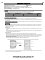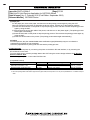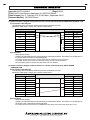
1
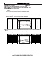
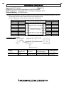
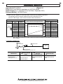
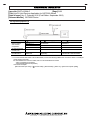
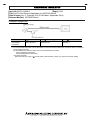
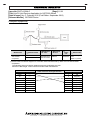
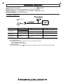
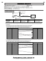
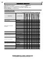
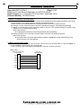
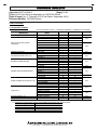
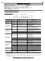
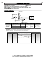
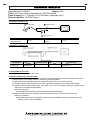
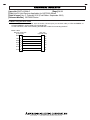
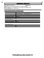
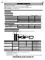
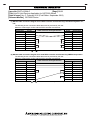
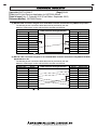
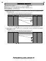
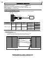
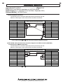
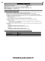
TECHNICAL BULLETIN
[Issue No.] GOT-A-0064-C
[Page] 1/39
[Title] List of Valid Devices Applicable for GOT2000 Series
[Date of Issue] Ver. C: February 2015 (First Edition: September 2013)
[Relevant Models] GOT2000 Series
Thank you for your continued support of Mitsubishi Graphic Operation Terminal (GOT).
The peripheral devices listed in this bulletin have been concluded by Mitsubishi to be applicable for the
GOT2000 series.
For how to use each product, refer to the respective product’s manual.
Regarding the production status of each product, confirm with the manufacturer.
Recommended Product
A product that complies with our standard.
Make sure that you use the product compliant with the specification (standard).
Compatible Product
A product that satisfies the requirements to be interfaced with Mitsubishi products.
(Note that satisfaction of Mitsubishi specifications is not guaranteed.)
Therefore, make sure to comply with the specifications for that product when using it together with Mitsubishi products.
Even when Compatible Products are used, some products may not be compatible with the GOT 2000 series. Because the
specifications of the products are changed according to the date of manufacture. When using Compatible Products, examine the
products fully and decide whether to use or not.
Discontinued Product
A product that has been introduced as Recommended Product or Compatible Product in the bulletin before. We think that you will
have difficulty to obtain the product because of production discontinuation and others.
Incompatible Product
A product that does not satisfy the requirements to be interfaced with Mitsubishi products.
Use Compatible Product.
HEAD OFFICE : TOKYO BUILDING, 2-7-3 MARUNOUCHI, CHIYODA-KU, TOKYO 100-8310, JAPAN
NAGOYA WORKS : 1-14, YADA-MINAMI 5-CHOME, HIGASHI-KU, NAGOYA, JAPAN
TECHNICAL BULLETIN
[Issue No.] GOT-A-0064-C
[Page] 2/39
[Title] List of Valid Devices Applicable for GOT2000 Series
[Date of Issue] Ver. C: February 2015 (First Edition: September 2013)
[Relevant Models] GOT2000 Series
Contents
1. Memory Card (CF card and SD card) ............................................................................................ 3
2. USB Memory .................................................................................................................................. 3
3. Barcode Reader ............................................................................................................................. 4
3.1 Compatible Products ............................................................................................................... 4
3.1.1 RS-232 connection .......................................................................................................... 4
3.1.2 RS-422/485 connection................................................................................................... 4
3.2 System equipment of barcode readers ................................................................................... 5
3.2.1 System equipment (1) ..................................................................................................... 5
3.2.2 System equipment (2) ..................................................................................................... 7
3.2.3 System equipment (3) ..................................................................................................... 8
3.2.4 System equipment (4) ..................................................................................................... 9
3.2.5 System equipment (5) ................................................................................................... 10
3.2.6 System equipment (6) ................................................................................................... 11
3.2.7 System equipment (7) ................................................................................................... 12
3.2.8 System equipment (8) ................................................................................................... 13
3.3 Compatible barcode types..................................................................................................... 14
3.4 How to read data by a barcode reader.................................................................................. 15
3.5 When using the GT21 model................................................................................................. 15
4. 2D Code Reader ........................................................................................................................... 16
4.1 Compatible Products ............................................................................................................. 16
4.2 System equipment of 2D code reader ................................................................................... 17
4.2.1 System equipment (1) ................................................................................................... 17
4.2.2 System equipment (2) ................................................................................................... 20
4.2.3 System equipment (3) ................................................................................................... 21
4.2.4 System equipment (4) ................................................................................................... 22
4.2.5 System equipment (5) ................................................................................................... 23
4.2.6 System equipment (6) ................................................................................................... 23
4.3 Compatible 2D code type ...................................................................................................... 23
4.4 How to read data by a 2D code reader ................................................................................. 23
4.5 When using the GT21 model................................................................................................. 24
5. Hubs for Ethernet Connection and Gateway Function ................................................................. 25
6. Video Camera ............................................................................................................................... 26
7. Display .......................................................................................................................................... 26
8. Speaker ........................................................................................................................................ 26
9. RFID Controller ............................................................................................................................. 27
9.1 Compatible Products ............................................................................................................. 27
9.1.1 RS-232 connection ........................................................................................................ 27
9.1.2 RS-422/485 connection................................................................................................. 27
9.2 System equipment of RFID controllers ................................................................................. 27
9.2.1 When using the RS-232 connection ............................................................................. 27
9.2.2 When using the RS-422/485 connection ...................................................................... 31
9.3 How to read data by an RFID controller ................................................................................ 33
9.4 The following RFID controllers are available for the external authentication. ....................... 33
10. USB Mouse Function.................................................................................................................. 34
11. USB Keyboard Function ............................................................................................................. 34
11.1 USB Keyboard ..................................................................................................................... 34
11.2 USB Barcode Reader .......................................................................................................... 34
11.3 USB RFID Controller ........................................................................................................... 34
11.4 Other device ........................................................................................................................ 35
12. USB Hub ..................................................................................................................................... 35
13. Wireless LAN Access Point ........................................................................................................ 35
14. Printer ......................................................................................................................................... 36
14.1 PictBridge compatible printer ................................................................................................... 36
14.2 Serial printer ............................................................................................................................. 37
HEAD OFFICE : TOKYO BUILDING, 2-7-3 MARUNOUCHI, CHIYODA-KU, TOKYO 100-8310, JAPAN
NAGOYA WORKS : 1-14, YADA-MINAMI 5-CHOME, HIGASHI-KU, NAGOYA, JAPAN
TECHNICAL BULLETIN
[Issue No.] GOT-A-0064-C
[Page] 3/39
[Title] List of Valid Devices Applicable for GOT2000 Series
[Date of Issue] Ver. C: February 2015 (First Edition: September 2013)
[Relevant Models] GOT2000 Series
1. Memory Card (CF card and SD card)
GOT
Supported memory card
GOT2000
GT27-MMR-Z
CF card (MITSUBISHI GT05-MEM-□C)
×
○
SD card (MITSUBISHI L1MEM-□GBSD)
○
×
For the applicable non-Mitsubishi memory cards (CF cards and SD cards), refer to the following Technical
Bulletins.
➟ Non-Mitsubishi CF card: No. GOT-A-0025 "Operation Check Results of Third Party CF Cards on
GOT1000 Series Units"
Non-Mitsubishi SD card: No. GOT-A-0065 "Operation Check Results of Non-Mitsubishi SD Cards on
GOT2000 Series Units"
2. USB Memory
Item
USB memory
Specification
USB hub compliant with USB2.0 (including forward-compatible with USB3.0 and
others) *1*2*3
*1: For the GT27, the USB memory has a capacity of 32GB.
*2: A USB memory with a particular function and others may not be available depending on the USB memory type.
Particular function examples:
- A composite device (including a hub function and a card reader function)
- A USB memory with an authentication function, an encryption function, or a security function including an anti-virus
function and others
- A USB memory whose functions are added by dedicated driver software.
*3: USB memory that has been formatted in FAT or FAT32 is available.
- FAT: Up to 2GB
- FAT32: Up to 32GB
HEAD OFFICE : TOKYO BUILDING, 2-7-3 MARUNOUCHI, CHIYODA-KU, TOKYO 100-8310, JAPAN
NAGOYA WORKS : 1-14, YADA-MINAMI 5-CHOME, HIGASHI-KU, NAGOYA, JAPAN
TECHNICAL BULLETIN
[Issue No.] GOT-A-0064-C
[Page] 4/39
[Title] List of Valid Devices Applicable for GOT2000 Series
[Date of Issue] Ver. C: February 2015 (First Edition: September 2013)
[Relevant Models] GOT2000 Series
3. Barcode Reader
3.1 Compatible Products
3.1.1 RS-232 connection
◎: Recommended product, ○: Operation validated, ×: Operation not checked
Operation validation
Refer to
Manufacturer
Model
GOT2000
GT SoftGOT2000
BR-530RS-B1
○
○
AIMEX Corporation
3.2.1
BW-880RS-B1 *1
○
○
DS2200-1100
○
○
DS2100-1114
○
○
3.2.1
GRYPHON D100
○
○
GRYPHON D130
○
○
DS2400N-□□□□
○
○
3.2.6
IDEC AUTO-ID SOLUTIONS
DS4800-1□00
○
○
Corporation
QD2130-□□
○
○
3.2.4
QD4130-□□
○
○
GBT4130-BK-BT
○
○
3.2.5
MG1100i-1D
○
○
3.2.4
PD7130-YB-PTR
○
○
BCH5542-STA
○
○
NEC Platforms, Ltd.
3.2.1
BCR5342H-STZ
○
○
OMRON Corporation
V520-RH21-6
○
○
3.2.2
OPT-5125-RS232C(H)
○
○
OPL-6735-RS232C(X04)
○
○
3.2.1
OPTOELECTRONICS CO.,LTD.
NFT-7175-RS-1
○
○
OPL-6845R-RS232
○
○
3.2.4
BL-210R
○
○
BL-210RK *2
×
◎
KEYENCE CORPORATION
3.2.1
BL-601
○
○
BL-N70R
○
○
SR-510
○
○
DENSO WAVE Incorporated
GT10B-SB
○
○
3.2.7
TLMS-3500RV
○
○
MARS TOHKEN SOLUTION
THLS-6712
○
○
3.2.1
CO.,LTD
THLS-6800
○
○
AC-812-000-D1
○
○
Nippon Systems Development
3.2.3
Co.,Ltd.
PDC-812-400-00+PDC-812-300-D1
◎
◎
LS2208
○
○
3.2.2
Motorola Solutions, Inc.
LI4278
○
○
3.2.1
Honeywell International Inc.
3800G-04E
○
○
3.2.4
*1: For the GOT2000 Series, turn on the barcode reader after any of the following conditions.
- More than two seconds have elapsed since the GOT is turned on.
- The logo [GOT2000] is displayed on the screen after the GOT is turned on.
*2: GT27 model and GT25 model are available only. (Configure the settings in the utility of the GOT to supply 5VDC.)
3.1.2 RS-422/485 connection
◎: Recommended product, ○: Operation validated, ×: Operation not checked
Operation validation
Refer to
Model
GOT2000
GT SoftGOT2000
Manufacturer
IDEC AUTO-ID SOLUTIONS
Corporation
DS2100N-1214
◎
HEAD OFFICE : TOKYO BUILDING, 2-7-3 MARUNOUCHI, CHIYODA-KU, TOKYO 100-8310, JAPAN
NAGOYA WORKS : 1-14, YADA-MINAMI 5-CHOME, HIGASHI-KU, NAGOYA, JAPAN
×
3.2.8
TECHNICAL BULLETIN
[Issue No.] GOT-A-0064-C
[Page] 5/39
[Title] List of Valid Devices Applicable for GOT2000 Series
[Date of Issue] Ver. C: February 2015 (First Edition: September 2013)
[Relevant Models] GOT2000 Series
3.2 System equipment of barcode readers
The following shows the equipment to configure with different types of barcode readers.
3.2.1 System equipment (1)
Manufacturer
Barcode reader
BR-530RS-B1
AIMEX Corporation
BW-880RS-B1
DS2200-1100
DS2100-1114
IDEC AUTO-ID
SOLUTIONS Corporation
NEC Platforms, Ltd.
OPTOELECTRONICS
CO.,LTD.
GRYPHON D100
Power supply unit
Included with a barcode
reader (An adapter (BB-60)
must be purchased
separately.)
Included with a barcode
reader
DSPW-2102
DSPW-2102
PG5 MAIN POWER
BLOCK
RS-232 cable
Included with a barcode reader
Included with a barcode reader
GT01-C30R2-25P *1
GT01-C30R2-25P *1
Included with a barcode reader
Sold separately:
CAB-327/CAB-350/CAB-362
GT01-C30R2-9S *1
GT01-C30R2-9S *1
Included with a barcode reader
*2
GRYPHON D130
UL310-0515
BCH5542-STA
BCR5342H-STZ
BCV5070 or CA1071
BCV5070 or BCA1071
OPT-5125-RS232C(H)
Not necessary
OPL-6735-RS232C(X04)
DC-5300T
Included with a barcode reader
NFT-7175-RS-1
GT27, GT25: Not
necessary
GT21: DC-5300T
GT27,GT25: Included with a
barcode reader
GT21: Power supply jack with
cable is necessary
BL-210R
Included with a barcode
reader
Included with a barcode reader
BL-210RK
Not necessary
KEYENCE
CORPORATION
BL-U1
BL-601
BL-U2
BL-N70R
SR-510
TLMS-3500RV
THLS-6712
Produced by the user
Refer to 1) below.
(5VDC is required.)
Produced by the user
Refer to 2) below. *3
Produced by the user
Refer to 3) below. *4
Included with a barcode reader
GT01-C30R2-9S
GT01-C30R2-25P *1
Included with a barcode reader
R3W005-025J
BL-U2
Not necessary *5
MARS TOHKEN
AD-6712
SOLUTION CO.,LTD
An adapter must be
THLS-6800
Included with a barcode reader
purchased separately.
Cradle:
STB4278-C0001WR
CBA-R01-S07PAR
Motorola Solutions, Inc.
LI4278
Power supply:
50-14000-010
*1: This is a Mitsubishi Electric product. Please contact your local Mitsubishi Electric or representative for purchasing the
cable.
*2: When purchasing OPT-5125-RS232C(H), select one with the same connector shape as OPL-6735-RS232C(X04).
*3: The OP-22149(1.5m) and the OP-25057 (conversion connector) manufactured by KEYENCE CORPORATION are
HEAD OFFICE : TOKYO BUILDING, 2-7-3 MARUNOUCHI, CHIYODA-KU, TOKYO 100-8310, JAPAN
NAGOYA WORKS : 1-14, YADA-MINAMI 5-CHOME, HIGASHI-KU, NAGOYA, JAPAN
TECHNICAL BULLETIN
[Issue No.] GOT-A-0064-C
[Page] 6/39
[Title] List of Valid Devices Applicable for GOT2000 Series
[Date of Issue] Ver. C: February 2015 (First Edition: September 2013)
[Relevant Models] GOT2000 Series
available.
*4: The OP-27937(2m) manufactured by KEYENCE CORPORATION is available.
*5: It is necessary to supply 24VDC to the barcode reader separately. For details, please refer to the manual of the barcode
reader to be used.
1) Cable connection diagram for a barcode reader manufactured by KEYENCE CORPORATION (BL-210RK)
The following shows connection cables that must be produced by the user.
Maximum cable length: confirm with the barcode reader manufacturer.
Barcode reader
Signal name
Pin No.
SG
1
Cable connection and signal direction
Pin No.
1
GOT
Signal name
CD
RD(RXD)
2
2
RD(RXD)
SD(TXD)
3
3
SD(TXD)
ER(DTR)
4
4
ER(DTR)
SG
5
5
SG
DR(DSR)
6
6
DR(DSR)
RS(RTS)
7
7
RS(RTS)
CS(CTS)
8
8
CS(CTS)
5V
9
9
5V
2) RS-232 cable connection diagram for a barcode reader manufactured by KEYENCE CORPORATION (BL-601,
BL-U1)
The following shows connection cables that must be produced by the user.
Maximum cable length: confirm with the barcode reader manufacturer.
Barcode reader
Signal name
Pin No.
FG
1
SD
Cable connection and signal direction
2
Pin No.
GOT
Signal name
Connector case
2
RD(RXD)
RD
3
3
SD(TXD)
RS
4
4
ER(DTR)
CS
5
5
SG
DR
6
6
DR(DSR)
SG
7
7
RS(RTS)
8
8
CS(CTS)
20
9
―
ER
HEAD OFFICE : TOKYO BUILDING, 2-7-3 MARUNOUCHI, CHIYODA-KU, TOKYO 100-8310, JAPAN
NAGOYA WORKS : 1-14, YADA-MINAMI 5-CHOME, HIGASHI-KU, NAGOYA, JAPAN
TECHNICAL BULLETIN
[Issue No.] GOT-A-0064-C
[Page] 7/39
[Title] List of Valid Devices Applicable for GOT2000 Series
[Date of Issue] Ver. C: February 2015 (First Edition: September 2013)
[Relevant Models] GOT2000 Series
3) Cable connection diagram for a barcode reader manufactured by KEYENCE CORPORATION (BL-601, BL-U2)
The following shows connection cables that must be produced by the user.
Maximum cable length: confirm with the barcode reader manufacturer.
Barcode reader
Signal name
Pin No.
Cable connection and signal direction
Pin No.
Connector case
GOT
Signal name
Connector case
RD
2
2
RD(RXD)
SD
3
3
SD(TXD)
ER
4
4
ER(DTR)
SG
5
5
SG
DR
6
6
DR(DSR)
RS
7
7
RS(RTS)
CS
8
8
CS(CTS)
―
9
9
―
3.2.2 System equipment (2)
Manufacturer
OMRON
Corporation
Motorola Solutions,
Inc.
Barcode reader
V520-RH21-6
(With dedicated
cable)
LS2208
Dedicated cable
V509-W012
CBA-R01-S07PAR
Power supply unit
S8VS-03005(A 100VAC
plug cable must be
purchased separately.)
symbol 50-14000-101R
HEAD OFFICE : TOKYO BUILDING, 2-7-3 MARUNOUCHI, CHIYODA-KU, TOKYO 100-8310, JAPAN
NAGOYA WORKS : 1-14, YADA-MINAMI 5-CHOME, HIGASHI-KU, NAGOYA, JAPAN
RS-232 cable
Produced by the user
Refer to 1) below.
Not necessary
TECHNICAL BULLETIN
[Issue No.] GOT-A-0064-C
[Page] 8/39
[Title] List of Valid Devices Applicable for GOT2000 Series
[Date of Issue] Ver. C: February 2015 (First Edition: September 2013)
[Relevant Models] GOT2000 Series
1) Cable connection diagram for a barcode reader manufactured by OMRON Corporation
The following shows connection cables that must be produced by the user.
Maximum cable length: confirm with the barcode reader manufacturer.
Signal
direction
Internal
connection
Barcode reader
Signal
name
FG
GOT
Pin No.
1
1
CD
SD(TXD) *1
2
2
RD(RXD)
Cable connection and signal direction
Pin No.
Signal name
RD(RXD) *1
3
3
SD(TXD)
RS(RTS)
4
4
ER(DTR)
CS(CTS)
5
5
SG
─
6
6
DR(DSR)
─
7
7
RS(RTS)
─
8
8
CS(CTS)
SG
9
9
─
*1: A dedicated cable, V509-W012 (cross cable), is used between the barcode reader and the cables mentioned
above. Even if the signal name for cable connection is SD-SD or RD-RD, the communication can be performed
with no problem.
3.2.3 System equipment (3)
Wireless
barcode reader
Attached cable
GOT
Barcode reader
dedicated communication unit
Manufacturer
Wireless barcode
reader
Barcode reader
dedicated
communication unit
Attached cable
AC-812-000-D1
Nippon Systems
Development Co.,Ltd.
PDC-812-400-00+
PDC-812-300-D1
Included with a barcode
reader
Included with a barcode
reader
HEAD OFFICE : TOKYO BUILDING, 2-7-3 MARUNOUCHI, CHIYODA-KU, TOKYO 100-8310, JAPAN
NAGOYA WORKS : 1-14, YADA-MINAMI 5-CHOME, HIGASHI-KU, NAGOYA, JAPAN
TECHNICAL BULLETIN
[Issue No.] GOT-A-0064-C
[Page] 9/39
[Title] List of Valid Devices Applicable for GOT2000 Series
[Date of Issue] Ver. C: February 2015 (First Edition: September 2013)
[Relevant Models] GOT2000 Series
3.2.4 System equipment (4)
Manufacturer
Barcode reader
QD2130-□□
QD4130-□□
MG1100i-1D
PD7130-YB-PTR
UL310-0515
CAB-350 *1
HK-CP13-A05
SET8-0935
8-0736-80 *1
CAB-433 *1
OPTOELECTRONI
CS CO.,LTD.
OPL-6845R-RS232
Included with a barcode reader
Included with a barcode reader *1
Honeywell
International Inc
3800G-04E
An adapter must be purchased
separately.
Included with a barcode reader
IDEC AUTO-ID
SOLUTIONS
Corporation
Power supply unit
RS-232 cable
*1: To connect the barcode reader to GT SoftGOT2000, connect the following USB/RS-232 conversion cables to a USB port
on the personal computer.
For the USB/RS-232 conversion cables, refer to Technical Bulletin FA-D-0036.
- DIFC-U2 (Diatrend Corporation)
- DAC01R2VD (Diatrend Corporation)
<Connection example>
[Barcode reader (RS-232)] + [ RS-232 cable] + [DAC01R2VD] + [DIFC-U2] + [Personal computer (USB)]
HEAD OFFICE : TOKYO BUILDING, 2-7-3 MARUNOUCHI, CHIYODA-KU, TOKYO 100-8310, JAPAN
NAGOYA WORKS : 1-14, YADA-MINAMI 5-CHOME, HIGASHI-KU, NAGOYA, JAPAN
TECHNICAL BULLETIN
[Issue No.] GOT-A-0064-C
[Page] 10/39
[Title] List of Valid Devices Applicable for GOT2000 Series
[Date of Issue] Ver. C: February 2015 (First Edition: September 2013)
[Relevant Models] GOT2000 Series
3.2.5 System equipment (5)
Manufacturer
IDEC AUTO-ID
SOLUTIONS
Corporation
Barcode reader
GBT4130-BK-BT
Power supply unit
PSAA18U-120
RS-232 cable
CAB-350 *1
*1: To connect the barcode reader to GT SoftGOT2000, connect the following USB/RS-232 conversion cables to a USB port
on the personal computer.
For the USB/RS-232 conversion cables, refer to Technical Bulletin FA-D-0036.
- DIFC-U2 (Diatrend Corporation)
- DAC01R2VD (Diatrend Corporation)
<Connection example>
[Barcode reader (RS-232)] + [ RS-232 cable] + [DAC01R2VD] + [DIFC-U2] + [Personal computer (USB)]
HEAD OFFICE : TOKYO BUILDING, 2-7-3 MARUNOUCHI, CHIYODA-KU, TOKYO 100-8310, JAPAN
NAGOYA WORKS : 1-14, YADA-MINAMI 5-CHOME, HIGASHI-KU, NAGOYA, JAPAN
TECHNICAL BULLETIN
[Issue No.] GOT-A-0064-C
[Page] 11/39
[Title] List of Valid Devices Applicable for GOT2000 Series
[Date of Issue] Ver. C: February 2015 (First Edition: September 2013)
[Relevant Models] GOT2000 Series
3.2.6 System equipment (6)
Manufacturer
IDEC AUTO-ID
SOLUTIONS
Corporation
Barcode reader
DS2400N-□□□□
DS4800-1□00
Dedicated
cable
Included with a
barcode reader
Terminal
box
CBX100
Power
supply
unit
RS-232 cable
PS5R-B24
Produced by the
user
Refer to 1) below.
1) RS-232 cable connection diagram for a barcode reader manufactured by IDEC AUTO-ID SOLUTIONS
Corporation.
The following shows connection cables that must be produced by the user.
Maximum cable length: confirm with the barcode reader manufacturer.
Barcode reader
Signal name
Pin No.
SGND
──
Cable connection and signal direction
Pin No.
1
GOT
Signal name
CD
TX
──
2
RD(RXD)
RTS
──
3
SD(TXD)
RX
──
4
ER(DTR)
CTS
──
5
SG
──
──
6
DR(DSR)
──
──
7
RS(RTS)
──
──
8
CS(CTS)
──
──
9
NC
HEAD OFFICE : TOKYO BUILDING, 2-7-3 MARUNOUCHI, CHIYODA-KU, TOKYO 100-8310, JAPAN
NAGOYA WORKS : 1-14, YADA-MINAMI 5-CHOME, HIGASHI-KU, NAGOYA, JAPAN
TECHNICAL BULLETIN
[Issue No.] GOT-A-0064-C
[Page] 12/39
[Title] List of Valid Devices Applicable for GOT2000 Series
[Date of Issue] Ver. C: February 2015 (First Edition: September 2013)
[Relevant Models] GOT2000 Series
3.2.7 System equipment (7)
2
1 Barcode reader
3
Manufacturer
Barcode reader
QD2130-□□
QD4130-□□
MG1100i-1D
UL310-0515
CAB-350 *1
HK-CP13-A05
8-0736-80 *1
OPTOELECTRONI
CS CO.,LTD.
OPL-6845R-RS232
Included with a barcode reader
Included with a barcode reader *1
Honeywell
International Inc
3800G-04E
An adapter must be purchased
separately.
Included with a barcode reader
IDEC DATALOGIC
Corporation
Power supply unit
RS-232 cable
*1: To connect the barcode reader to GT SoftGOT2000, connect the following USB/RS-232 conversion cables to a USB port
on the personal computer.
For the USB/RS-232 conversion cables, refer to Technical Bulletin FA-D-0036.
- DIFC-U2 (Diatrend Corporation)
- DAC01R2VD (Diatrend Corporation)
<Connection example>
[Barcode reader (RS-232)] + [ RS-232 cable] + [DAC01R2VD] + [DIFC-U2] + [Personal computer (USB)]
HEAD OFFICE : TOKYO BUILDING, 2-7-3 MARUNOUCHI, CHIYODA-KU, TOKYO 100-8310, JAPAN
NAGOYA WORKS : 1-14, YADA-MINAMI 5-CHOME, HIGASHI-KU, NAGOYA, JAPAN
TECHNICAL BULLETIN
[Issue No.] GOT-A-0064-C
[Page] 13/39
[Title] List of Valid Devices Applicable for GOT2000 Series
[Date of Issue] Ver. C: February 2015 (First Edition: September 2013)
[Relevant Models] GOT2000 Series
3.2.8 System equipment (8)
Trigger switch
1 Barcode reader
3 Terminal box
4 RS-422/485 cable
GOT
2 Dedicated cable
Manufacturer
IDEC AUTO-ID
SOLUTIONS
Corporation
Barcode reader
DS2100N-1214
Dedicated cable
Included with a
barcode reader
Terminal box
CBX100
RS-422/485 cable
Produced by the user
Refer to 1) below.
1) RS-422/485 cable connection diagram for a barcode reader manufactured by IDEC AUTO-ID SOLUTIONS
Corporation.
a) For connection using the RS-422/485 interface of the GOT or GT15-RS4-9S
The following shows connection cables that must be produced by the user.
Maximum cable length: confirm with the barcode reader manufacturer.
Barcode reader
Signal name
Pin No.
―
―
TX(+)
Cable connection and signal direction
Pin No.
1
GOT
Signal name
SDA
2
3
2
RDA
RX(+)
3
RSA
TX(-)
4
4
CSA
RX(-)
5
5
SG
―
―
6
SDB
SGND
7
7
RDB
―
―
8
RSB
―
―
9
CSB
b) For connection using GT15-RS4-TE
The following shows connection cables that must be produced by the user.
Maximum cable length: confirm with the barcode reader manufacturer.
Barcode reader
Signal name
Pin No.
―
―
2
TX(+)
RX(+)
Cable connection and signal direction
Pin No.
1
GOT
Signal name
SDA1
2
SDB1
3
3
RDA1
TX(-)
4
4
RDB1
RX(-)
5
5
SDA2
―
―
6
SDB2
SGND
7
7
RDA2
―
―
8
RDB2
―
―
9
SG
―
―
10
FG
HEAD OFFICE : TOKYO BUILDING, 2-7-3 MARUNOUCHI, CHIYODA-KU, TOKYO 100-8310, JAPAN
NAGOYA WORKS : 1-14, YADA-MINAMI 5-CHOME, HIGASHI-KU, NAGOYA, JAPAN
TECHNICAL BULLETIN
[Issue No.] GOT-A-0064-C
[Page] 14/39
[Title] List of Valid Devices Applicable for GOT2000 Series
[Date of Issue] Ver. C: February 2015 (First Edition: September 2013)
[Relevant Models] GOT2000 Series
3.3 Compatible barcode types
The following barcode reader communication settings are supported by the GOT.
○: Can be read in the GOT, △: Partly restricted, ×: Unreadable in GOT
Barcode type
Nippon Systems Development Co.,Ltd.
Motorola Solutions, Inc.
Honeywell International Inc.
*1: Only JAN is supported.
THLS-6712
THLS-6800
AC-812-000-D1
LS2208
LI4278
3800G-04E
○
○
○
○
○
○
○
○
○
○
○
○
○
○
○
○
○
○
○
○
○
○
○
○
○
○
○
○
○
○
○
○
○
○
○
○
○
○
○
○
○
○
○
○
○
○
○
○
○
○
○
○
○
○
○
○
○
○
○
○
○
○
○
○
○
○
○
○
○
○
○
○
○
○
○
○
○
○
○
○
○
○
○
○
○
○
○
○
○
○
○
○
○
○
○
○
○
○
○
○
○
○
○
○
○
○
○
○
○
○
○
○
×
×
○
○
○
○
○
○
○
○
○
○
○
○
○
○
○
○
○
○
○
○
×
○
○
○
○
○
○
○
○
○
○
○
○
○
○
○
△
*1
○
○
○
○
○
○
×
○
○
○
HEAD OFFICE : TOKYO BUILDING, 2-7-3 MARUNOUCHI, CHIYODA-KU, TOKYO 100-8310, JAPAN
NAGOYA WORKS : 1-14, YADA-MINAMI 5-CHOME, HIGASHI-KU, NAGOYA, JAPAN
○
×
×
○
○
○
○
○
○
○
○
○
○
○
×
○
○
○
○
○
×
×
○
×
×
×
×
×
×
×
×
×
×
×
○
○
○
×
×
×
×
○
×
○
○
○
○
○
○
×
×
×
×
×
×
×
×
○
○
○
×
○
○
○
○
○
○
×
×
○
○
○
○
○
○
○
○
○
×
○
×
○
○
○
○
○
○
○
×
×
○
○
○
○
○
○
○
○
○
○
×
×
×
×
×
×
×
○
○
×
○
×
×
×
×
×
×
×
×
×
×
×
IATA 2of5
TLMS-3500RV
MARS TOHKEN SOLUTION CO.LTD.
○
○
○
○
○
○
○
○
○
○
○
○
○
○
○
○
○
○
○
○
○
○
○
○
○
○
○
○
MSI/Plessy
DENSO WAVE INCORPORATED
ITF
(2of5Interleaved)
KEYENCE CORPORATION
2of5 (industrial)
OPTOELECTRONICS CO.,LTD.
NW-7
(CODABAR)
OMRON Corporation
CODE-128
NEC Platforms, Ltd.
CODE-93
IDEC AUTO-ID SOLUTIONS
Corporation
BR-530RS-B1
BW-880RS-B1
DS2200-1100
DS2100-1114
GRYPHON D100
GRYPHON D130
DS2400N-□□□□
DS4800-1□00
QD2130-□□
DQ4130-□□
GBT4130-BK-BT
MG1100i-1D
PD7130-YB-PTR
DS2100N-1214
BCH5542-STA
BCR5342H-STZ
V520-RH21-6
OPT-5125-RS232C(H)
OPL-6735-RS232C(X04)
NFT-7175-RS-1
OPL-6845R-RS232
BL-210R
BL-210RK
BL-601
BL-N70R
SR-510
HR-50R
GT10B-SB
CODE-39
AIMEX Corporation
Barcode reader
WPC (JAN, EAN,
UPC)
Manufacturer
○
×
×
×
TECHNICAL BULLETIN
[Issue No.] GOT-A-0064-C
[Page] 15/39
[Title] List of Valid Devices Applicable for GOT2000 Series
[Date of Issue] Ver. C: February 2015 (First Edition: September 2013)
[Relevant Models] GOT2000 Series
3.4 How to read data by a barcode reader
Please refer to the followings for the data transfer format (header/terminator settings and others) that can be
used in the GOT or the setting method to read data by a barcode reader.
(a) Data transfer format (header/terminator settings and others) that can be used in the GOT.
(b) Setting to connect a barcode reader to the GOT. ([Peripheral Setting] on GT Designer3(GOT2000))
(c) Setting to write the data, read by a barcode reader, to the PLC CPU. ([Detail Setting] in the [Bar Code]
dialog box on GT Designer3(GOT2000))
Refer to the following.
➟ GT Designer3 (GOT2000) Screen Design Manual (SH-081220ENG)
(d) Setting procedure from connecting a barcode reader to the GOT until reading a barcode.
Refer to the following.
➟ GOT2000 Series Connection Manual (Microcomputer, MODBUS Products, Peripherals) For GT
Works3 Version1 (SH-081200ENG)
3.5 When using the GT21 model
To connect the barcode reader with the built-in RS-232 port (on the back side) of GT2103-PMBDS or
GT2103-PMBDS2, use the cable GT10-C02H-6PT9P.
To use GT2104-R, refer to the following and fabricate a cable for connecting the GOT.
■User cable
Barcode reader side
(D-sub 9-pin)
GOT side
(separate wire)
RXD 2
RD
TXD 3
SD
DSR 6
DR
DTR 4
ER
5
SG
RTS 7
RS
CTS 8
CS
SG
HEAD OFFICE : TOKYO BUILDING, 2-7-3 MARUNOUCHI, CHIYODA-KU, TOKYO 100-8310, JAPAN
NAGOYA WORKS : 1-14, YADA-MINAMI 5-CHOME, HIGASHI-KU, NAGOYA, JAPAN
TECHNICAL BULLETIN
[Issue No.] GOT-A-0064-C
[Page] 16/39
[Title] List of Valid Devices Applicable for GOT2000 Series
[Date of Issue] Ver. C: February 2015 (First Edition: September 2013)
[Relevant Models] GOT2000 Series
4. 2D Code Reader
4.1 Compatible Products
◎: Recommended product, ○: Operation validated, ×: Operation not checked
Operation validation
Reference
Manufacturer
Model
GOT2000
GT SoftGOT2000
AIMEX Corporation
IT4600SR-RS
○
○
4.2.1
MATRIX210-21□-□□□
○
○
MATRIX300-□□□-□□□
○
○
4.2.4
MATRIX410-□□□-0□0
○
○
IDEC AUTO-ID SOLUTIONS
GD4430-□□
○
○
Corporation
GD4430-□□-HD
○
○
4.2.3
GBT4430-□□
○
○
MG1100i-2D
○
○
M3200i Series
○
○
OMRON Corporation
V400-F250
○
○
4.2.1
OPD-7435
○
○
OPTOELECTRONICS CO.,LTD.
NFD1267 *1
○
4.2.1
×
OPI-3601-V
○
○
TL-30
○
○
TL-40
○
○
KEYENCE CORPORATION
4.2.1
SR-510
○
○
HR-100
○
○
GT10Q-SB
○
○
4.2.2
GT10Q-SR
◎
◎
GT11Q-SR
○
○
4.2.1
DENSO WAVE INCORPORATED
QB20K *1
○
×
QD20
○
○
AT10Q-SM
○
○
4.2.3
THIR-3000N
◎
◎
THIR-6000
○
○
4.2.1
MARS TOHKEN SOLUTION CO.LTD. TFIR-31
○
○
THIR-6200DDM
○
○
THIR-6780R
○
○
DataMan 100
○
○
4.2.1
DataMan 7500/7500LR
○
○
DataMan 7550/7550LR
○
○
Cognex K.K.
DataMan 750/750S
○
○
DataMan 200 *2
○
○
4.2.3
○
DataMan 8100/8500
◎
4.2.1
Motorola Solutions, Inc.
DS6608-RS-DOS/V
◎
◎
1900GSR-2
○
○
4.2.3
Honeywell International Inc.
*1: GT27 model and GT25 model are available only. (5VDC is required.)
*2: Configure the communication settings of the DataMan 200 and the GOT as shown below.
Setting item
Set value
Baud rate
115200 bps
Data length
8 bits or 7 bits
Stop bit
None, Even number or odd number
Parity
1 bit or 2 bits
HEAD OFFICE : TOKYO BUILDING, 2-7-3 MARUNOUCHI, CHIYODA-KU, TOKYO 100-8310, JAPAN
NAGOYA WORKS : 1-14, YADA-MINAMI 5-CHOME, HIGASHI-KU, NAGOYA, JAPAN
TECHNICAL BULLETIN
[Issue No.] GOT-A-0064-C
[Page] 17/39
[Title] List of Valid Devices Applicable for GOT2000 Series
[Date of Issue] Ver. C: February 2015 (First Edition: September 2013)
[Relevant Models] GOT2000 Series
4.2 System equipment of 2D code reader
The following shows the equipment to configure with different types of 2D code readers.
4.2.1 System equipment (1)
Manufacturer
AIMEX Corporation
OMRON
Corporation
OPTOELECTRON
ICS CO.,LTD.
KEYENCE
CORPORATION
DENSO WAVE
INCORPORATED
MARS TOHKEN
SOLUTION
CO.LTD.
2D code
reader
IT4600SR-RS
Included with a 2D code reader
V400-F250
Not necessary *1*2
OPD-7435
Included with a 2D code reader
NFD1267
Not necessary *3
OPI-3601-V
Included with a 2D code reader
TL-30
TL-U1
TL-40
SR-510
HR-100
TL-U1
BL-U2
OP-87530
GT10Q-SR
AD1005/3600
GT11Q-SR
QB20/20-HD
QB20K
AD1005/3600
2000639
Included with a 2D code reader
QD20
Not necessary *1*2
THIR-3000N
S-8440
TFIR-3102
Not necessary *1
Power supply unit
RS-232 cable
Included with a 2D code reader
Purchased by the user (V400-W24)
Including a 24VDC power cable
Included with a 2D code reader
Produced by the user
Refer to 1) below.
(5VDC is required.)
Included with a 2D code reader
For GT27and GT25, refer to 2) below.
GT21 when used, use the cable to the 2D
code reader is shipped
Included with a 2D code reader
GT01-C30R2-9S *4
HR-1C3RC
GT27,GT25,GT21:
・CBG1-RS2000/9
・CBG1-RS5000/9-1
・GT10Q RS232C/2m Curl
SoftGOT2000: *5
CBG11-RS2000/9
496800-0040
Included with a 2D code reader
Produced by the user
Refer to 3) below.
Included with a 2D code reader *5 *6
Produced by the user
Refer to 4) below.
Included with a 2D code reader
Included with a 2D code reader
Included with a 2D code reader
Included with a 2D code reader
DM100-RS232-000
DM42206139-04
DM42203758-03S
THIR-6000
Included with a 2D code reader
TFIR-31
Included with a 2D code reader
THIR-6200DDM Included with a 2D code reader
THIR-6780R
Included with a 2D code reader
DataMan 100
DM100-RWR-000
Cognex K.K.
DataMan 7500
Included with a 2D code reader
DataMan 7550
Included with a 2D code reader
Motorola Solutions, DS6608-RS-DO
Included with a 2D code reader
Included with a 2D code reader *5
Inc.
S/V
*1: It is necessary to supply 24VDC to the 2D code reader separately. For details, please refer to the manual of the 2D code
reader to be used.
*2: For adjusting settings of the 2D code reader by using the monitor, please refer to the manual of the 2D code reader to be
used.
*3: It is necessary to supply 5VDC to the 2D code reader separately. For details, please refer to the manual of the 2D code
reader to be used.
HEAD OFFICE : TOKYO BUILDING, 2-7-3 MARUNOUCHI, CHIYODA-KU, TOKYO 100-8310, JAPAN
NAGOYA WORKS : 1-14, YADA-MINAMI 5-CHOME, HIGASHI-KU, NAGOYA, JAPAN
TECHNICAL BULLETIN
[Issue No.] GOT-A-0064-C
[Page] 18/39
[Title] List of Valid Devices Applicable for GOT2000 Series
[Date of Issue] Ver. C: February 2015 (First Edition: September 2013)
[Relevant Models] GOT2000 Series
*4: This is a Mitsubishi Electric product. Please contact your local Mitsubishi Electric or representative for purchasing the
cable.
*5: To connect the 2D code reader to GT SoftGOT2000, connect the following USB/RS-232 conversion cables to a USB port
on the personal computer.
For the USB/RS-232 conversion cables, refer to Technical Bulletin FA-D-0036.
- DIFC-U2 (Diatrend Corporation)
- DAC01R2VD (Diatrend Corporation)
<Connection example>
[2D code reader (RS-232)] + [ RS-232 cable] + [DAC01R2VD] + [DIFC-U2] + [Personal computer (USB)]
*6: With the USB/RS-232 conversion cables (DIFC-U2 and DAC01R2VD), configure the 2D code reader setting so that the
RS/CS control is not performed.
HEAD OFFICE : TOKYO BUILDING, 2-7-3 MARUNOUCHI, CHIYODA-KU, TOKYO 100-8310, JAPAN
NAGOYA WORKS : 1-14, YADA-MINAMI 5-CHOME, HIGASHI-KU, NAGOYA, JAPAN
TECHNICAL BULLETIN
[Issue No.] GOT-A-0064-C
[Page] 19/39
[Title] List of Valid Devices Applicable for GOT2000 Series
[Date of Issue] Ver. C: February 2015 (First Edition: September 2013)
[Relevant Models] GOT2000 Series
1) RS-232 cable connection diagram for a 2D code reader manufactured by OPTOELECTRONICS CO., LTD.
The following shows connection cables that must be produced by the user.
Maximum cable length: confirm with the 2D code reader manufacturer.
2D code reader
Signal name
Pin No.
Trigger
Green
OK-
Cable connection and signal direction
Pin No.
1
GOT
Signal name
CD
Yellow
2
RD(RXD)
NG
Blue
3
SD(TXD)
SD
Purple
4
DTR(ER)
RD
Orange
5
SG
RS
Brown
6
DSR(DR)
CS
Gray
7
RS(RTS)
+5V
Red
8
CS(CTS)
GND
White
9
5V
2) RS-232 cable connection diagram for a 2D code reader manufactured by KEYENCE CORPORATION
The following shows connection cables that must be produced by the user.
Maximum cable length: confirm with the 2D code reader manufacturer.
2D code reader
Signal name
Pin No.
N.C
1
Cable connection and signal direction
Pin No.
1
GOT
Signal name
CD
SD(TXD)
2
2
RD(RXD)
RD(RXD)
3
3
SD(TXD)
N.C
4
4
DTR(ER)
SG
5
5
SG
N.C
6
6
DSR(DR)
CS(CTS)
7
7
RS(RTS)
RS(RTS)
8
8
CS(CTS)
N.C
9
9
──
3) RS-232 cable connection diagram for a 2D code reader manufactured by DENSO WAVE INCORPORATED
The following shows connection cables that must be produced by the user.
Maximum cable length: confirm with the 2D code reader manufacturer.
2D code reader
Signal name
Pin No.
──
──
/TXD
Cable connection and signal direction
Pin No.
1
2
2
GOT
Signal name
CD
RD(RXD)
/RXD
3
3
SD(TXD)
──
──
4
DTR(ER)
GND
5
5
SG
──
──
6
DSR(DR)
CTS
7
7
RS(RTS)
RTS
8
8
CS(CTS)
──
──
9
NC
HEAD OFFICE : TOKYO BUILDING, 2-7-3 MARUNOUCHI, CHIYODA-KU, TOKYO 100-8310, JAPAN
NAGOYA WORKS : 1-14, YADA-MINAMI 5-CHOME, HIGASHI-KU, NAGOYA, JAPAN
TECHNICAL BULLETIN
[Issue No.] GOT-A-0064-C
[Page] 20/39
[Title] List of Valid Devices Applicable for GOT2000 Series
[Date of Issue] Ver. C: February 2015 (First Edition: September 2013)
[Relevant Models] GOT2000 Series
4) RS-232 cable connection diagram for a 2D code reader manufactured by MARS TOHKEN SOLUTION
CO.LTD.
The following shows connection cables that must be produced by the user.
Maximum cable length: confirm with the 2D code reader manufacturer.
2D code reader
Signal name
Pin No.
──
──
Cable connection and signal direction
Pin No.
1
GOT
Signal name
CD *1
RXD /RD-
2
2
RD(RXD)
TXD /TD+
3
3
SD(TXD)
──
──
4
DTR(ER)
GND
5
5
SG
──
──
6
DSR(DR)
──
──
7
RS(RTS)
RTS
11
8
CS(CTS)
CTS
12
9
──
4.2.2 System equipment (2)
Manufacturer
DENSO WAVE
INCORPORATED
2D code
reader
GT10Q-SB
Power supply unit
Included with a 2D code reader
(A Bluetooth adapter
(BA-10RKU) must be purchased
separately.)
RS-232 cable
CBBA-RS2000/9
HEAD OFFICE : TOKYO BUILDING, 2-7-3 MARUNOUCHI, CHIYODA-KU, TOKYO 100-8310, JAPAN
NAGOYA WORKS : 1-14, YADA-MINAMI 5-CHOME, HIGASHI-KU, NAGOYA, JAPAN
TECHNICAL BULLETIN
[Issue No.] GOT-A-0064-C
[Page] 21/39
[Title] List of Valid Devices Applicable for GOT2000 Series
[Date of Issue] Ver. C: February 2015 (First Edition: September 2013)
[Relevant Models] GOT2000 Series
4.2.3 System equipment (3)
2D code
reader
GD4430-□□
GD4430-□□-HD
GBT4430-□□
MG1100i-2D
M3200i Series
UL310-0515, or 5V power supply from
the GOT standard interface *2
CAB-350 *3
11-0387 or HK-CP13-A05
PSAA18U-120
8-0736-80 *3
8-0730-54 *3
DENSO WAVE
INCORPORATED
AT10Q-SM
Included with a 2D code reader
Included with a 2D code reader
DMA-24KIT-00, DM100-PWR-000
DM700-RS232-00
Cognex K.K.
DataMan 750
DataMan 750S
DataMan 8100 *1
DataMan 8500 *1
DM100-PWR-00
DM8000-RS232-00
Manufacturer
IDEC AUTO-ID
SOLUTIONS
Corporation
Power supply unit
RS-232 cable
Honeywell
International
1900GSR-2
Included with a 2D code reader
Included with a 2D code reader
Inc.
*1: DataMan 8100/8500 requires the communication module DMCM-SERIALM-00.
*2: It is necessary to supply 5VDC to the 2D code reader separately. For details, please refer to the manual of the 2D code
reader to be used.
*3: To connect the 2D code reader to GT SoftGOT2000, connect the following USB/RS-232 conversion cables to a USB port
on the personal computer.
For the USB/RS-232 conversion cables, refer to Technical Bulletin FA-D-0036.
- DIFC-U2 (Diatrend Corporation)
- DAC01R2VD (Diatrend Corporation)
<Connection example>
[2D code reader (RS-232)] + [ RS-232 cable] + [DAC01R2VD] + [DIFC-U2] + [Personal computer (USB)]
HEAD OFFICE : TOKYO BUILDING, 2-7-3 MARUNOUCHI, CHIYODA-KU, TOKYO 100-8310, JAPAN
NAGOYA WORKS : 1-14, YADA-MINAMI 5-CHOME, HIGASHI-KU, NAGOYA, JAPAN
TECHNICAL BULLETIN
[Issue No.] GOT-A-0064-C
[Page] 22/39
[Title] List of Valid Devices Applicable for GOT2000 Series
[Date of Issue] Ver. C: February 2015 (First Edition: September 2013)
[Relevant Models] GOT2000 Series
4.2.4 System equipment (4)
Trigger switch
1 2D code reader
3 Terminal box
5 RS-232 cable
GOT
2 Dedicated cable
4 Power supply unit
Manufacturer
IDEC AUTO-ID
SOLUTIONS
Corporation
Barcode reader
MATRIX210-21□-□□□
MATRIX300-□□□-□□□
MATRIX410-□□□-0□0
Dedicated
cable
Included with a
2D code reader
CAB-DS0□-S
CAB-MS01
Terminal
box
CBX100
Power
supply unit
PS5R-B24
RS-232 cable
Produced by the
user
Refer to 1) below.
1) RS-232 cable connection diagram for a 2D code reader manufactured by IDEC AUTO-ID SOLUTIONS
Corporation.
The following shows connection cables that must be produced by the user.
Maximum cable length: confirm with the barcode reader manufacturer.
Barcode reader
Signal name
Pin No.
SGND
──
Cable connection and signal direction
Pin No.
1
GOT
Signal name
CD
TX
──
2
RD(RXD)
RTS
──
3
SD(TXD)
RX
──
4
ER(DTR)
CTS
──
5
SG
──
──
6
DR(DSR)
──
──
7
RS(RTS)
──
──
8
CTS
──
──
9
NC
HEAD OFFICE : TOKYO BUILDING, 2-7-3 MARUNOUCHI, CHIYODA-KU, TOKYO 100-8310, JAPAN
NAGOYA WORKS : 1-14, YADA-MINAMI 5-CHOME, HIGASHI-KU, NAGOYA, JAPAN
TECHNICAL BULLETIN
[Issue No.] GOT-A-0064-C
[Page] 23/39
[Title] List of Valid Devices Applicable for GOT2000 Series
[Date of Issue] Ver. C: February 2015 (First Edition: September 2013)
[Relevant Models] GOT2000 Series
4.2.5 System equipment (5)
2D code reader
Dedicated cable
GOT
Power supply unit
Manufacturer
KEYENCE
CORPORATION
2D code reader
TL-30
Dedicated cable
Included with a 2D code
reader
Power supply unit
TL-U1
4.2.6 System equipment (6)
Manufacturer
Cognex K.K.
2D code
reader
DataMan 200
Dedicated cable
CCB-84901-1003-△
△
Power supply
unit
CPS-AC-POE1A-△
△
RS-232 cable
CCB-M8X4-△△
4.3 Compatible 2D code type
Only “QR code” is supported by the GOT.
4.4 How to read data by a 2D code reader
Please refer to the followings for the data transfer format (header/terminator settings and others) that can be
used in the GOT or the setting method to read data by a 2D code reader.
(a) Data transfer format (header/terminator settings and others) that can be used in the GOT.
(b) Setting to connect a 2D code reader to the GOT. ([Peripheral Setting] on GT Designer3(GOT2000))
(c) Setting to write the data, read by a 2D code reader, to the PLC CPU. ([Detail Setting] in the [Bar Code]
dialog box on GT Designer3(GOT2000))
Refer to the following.
➟ GT Designer3 (GOT2000) Screen Design Manual (SH-081220ENG)
(d) Setting the procedure from connecting a 2D code reader to the GOT until reading 2D code data.
Refer to the following.
➟ GOT2000 Series Connection Manual (Microcomputer, MODBUS Products, Peripherals) For GT
Works3 Version1 (SH-081200ENG)
HEAD OFFICE : TOKYO BUILDING, 2-7-3 MARUNOUCHI, CHIYODA-KU, TOKYO 100-8310, JAPAN
NAGOYA WORKS : 1-14, YADA-MINAMI 5-CHOME, HIGASHI-KU, NAGOYA, JAPAN
TECHNICAL BULLETIN
[Issue No.] GOT-A-0064-C
[Page] 24/39
[Title] List of Valid Devices Applicable for GOT2000 Series
[Date of Issue] Ver. C: February 2015 (First Edition: September 2013)
[Relevant Models] GOT2000 Series
4.5 When using the GT21 model
To connect the barcode reader with the built-in RS-232 port (on the back side) of GT2103-PMBDS or
GT2103-PMBDS2, use the cable GT10-C02H-6PT9P.
To use GT2104-R, refer to the following and fabricate a cable for connecting the GOT.
■User cable
Barcode reader side
(D-sub 9-pin)
GOT side
(separate wire)
RXD 2
RD
TXD 3
SD
DSR 6
DR
DTR 4
ER
5
SG
RTS 7
RS
CTS 8
CS
SG
HEAD OFFICE : TOKYO BUILDING, 2-7-3 MARUNOUCHI, CHIYODA-KU, TOKYO 100-8310, JAPAN
NAGOYA WORKS : 1-14, YADA-MINAMI 5-CHOME, HIGASHI-KU, NAGOYA, JAPAN
TECHNICAL BULLETIN
[Issue No.] GOT-A-0064-C
[Page] 25/39
[Title] List of Valid Devices Applicable for GOT2000 Series
[Date of Issue] Ver. C: February 2015 (First Edition: September 2013)
[Relevant Models] GOT2000 Series
5. Hubs for Ethernet Connection and Gateway Function
(Compatible Product)
Manufacturer
Allied Telesis K.K.
I-O DATA DEVICE, INC.
KEYENCE CORPORATION
PHOENIX CONTACT
Mitsubishi Electric Corporation
Mitsubishi Cable Industries,Ltd.
CentreCOM FS708XL
CentreCOM FS705TX
ETX-ESH5
NE-V08
FL SWITCH SF 8TX
NZ2EHG-T8
ET10618
Model
CentreCOM MR815TL
CentreCOM FS705TX V2
ETX-SH5
CentreCOM RH505EL
FL SWITCH 5TX (Hardware version 13 or later)
ST12904-AC
(Discontinued Product *1)
Manufacturer
Model
Allied Telesis K.K.
CentreCOM MR820TR
CentreCOM 3012TR V2
Mitsubishi Cable Industries,Ltd.
ST12608
*1: Discontinued Products are not checked with GOT2000 Series.
(Incompatible Product *2)
Manufacturer
BUFFALO INC.
LSW-TX-5EP
*2: Incompatible Products are not checked with GOT2000 Series.
Model
HEAD OFFICE : TOKYO BUILDING, 2-7-3 MARUNOUCHI, CHIYODA-KU, TOKYO 100-8310, JAPAN
NAGOYA WORKS : 1-14, YADA-MINAMI 5-CHOME, HIGASHI-KU, NAGOYA, JAPAN
TECHNICAL BULLETIN
[Issue No.] GOT-A-0064-C
[Page] 26/39
[Title] List of Valid Devices Applicable for GOT2000 Series
[Date of Issue] Ver. C: February 2015 (First Edition: September 2013)
[Relevant Models] GOT2000 Series
6. Video Camera
Precautions
Some video cameras may require a separate power supply unit.
Regarding a required power supply unit for a video camera, confirm with the manufacturer.
(Compatible Product)
Manufacturer
Sony Corporation
TOSHIBA TELI CORPORATION
Mitsubishi Electric Corporation
XC-ST70 *1
XC-ES50 *1
XC-ES30 *1
XC-ST70CE *2
CS8630i *1
CS8310Bi *1
CIT-9510M *3*5
CIT-8000 *3*5
C-4010 *3*5
C-2915 *3*5
Model
XC-ST50 *1
XC-ES50L *1
XC-EI50 *1
XC-ST30CE *2
CS8550i-51 *1*4
XC-ST51 *1
XC-ES51 *1
XC-EI30 *1
XC-ES30CE *2
CS8311Bi *2
CIT-8800M *3*5
CIT-8510M *3*5
C-2670 *3*5
C-2600 *3*5
SENSOR TECHNOLOGY CO.,LTD
STC-620BJ2 *3
(SENTECH)
*1: EIA format (Monochrome) Set NTSC for the video input signal of the communication settings.
*2: CCIR format (Monochrome) Set PAL for the video input signal of the communication settings.
*3: NTSC format (Color)
*4: Set the 1/60s interlace mode for the video output mode (VIDEO) of the dipswitch on the camera rear panel.
*5: Some video cameras may require a separate power supply unit or the equipment for converting the specifications to
Mitsubishi specifications. For details, check the manual of the video camera to be used.
7. Display
(Compatible Product)
Manufacturer
Mitsubishi Electric Corporation
RDT1713LM
RDT234WLM
RDT235WLM
RDT242WH
Model
RDT198LM
RDT234WX
RDT235WX
RDT223WLM
RDT234WX-3D
RDT241WEX
8. Speaker
For a sound output unit of the GOT, use a speaker with amplifier.
Use a speaker compatible with the following specifications.
Item
Specification
Sound output terminal
For connecting external L/R speakers, 1 channel for each speaker (2Vp-p,
0.4mW (for rated load 10kΩ)
Applicable jack
Φ3.5 stereo mini jack, straight type
Playable file
Windows WAV format 8.000kHz, 16 bits, mono (8 seconds/sound file)
HEAD OFFICE : TOKYO BUILDING, 2-7-3 MARUNOUCHI, CHIYODA-KU, TOKYO 100-8310, JAPAN
NAGOYA WORKS : 1-14, YADA-MINAMI 5-CHOME, HIGASHI-KU, NAGOYA, JAPAN
TECHNICAL BULLETIN
[Issue No.] GOT-A-0064-C
[Page] 27/39
[Title] List of Valid Devices Applicable for GOT2000 Series
[Date of Issue] Ver. C: February 2015 (First Edition: September 2013)
[Relevant Models] GOT2000 Series
9. RFID Controller
9.1 Compatible Products
9.1.1 RS-232 connection
Manufacturer
LS Industrial Systems Co., Ltd.
OMRON Corporation
MARS TOHKEN SOLUTION CO.LTD..
PONGEE INDUSTRIES CO., LTD
◎: Recommended product,○: Operation validated, ×: Operation not checked
Operation validation
Model
GOT2000
GT SoftGOT2000
LSRF-C
◎
◎
V600/V620
◎
◎
ICU-60S
◎
◎
×
ICU-215
◎
PUA-310
◎
◎
9.1.2 RS-422/485 connection
◎: Recommended product,○: Operation validated, ×: Operation not checked
Operation validation
Model
GOT2000
GT SoftGOT2000
×
V600
◎
V680
×
◎
Manufacturer
OMRON Corporation
9.2 System equipment of RFID controllers
9.2.1 When using the RS-232 connection
The following shows the equipment to configure with different types of RFID controllers.
1 IC tag
2 RFID reader/writer
3 RFID controller
4 RS-232 cable
Manufacturer
LS Industrial Systems
Co., Ltd.
IC tag
RS-232 cable
Produced by the user
LSRT125
LSRF-L
LSRF-C
Refer to (1) below *1
Produced by the user
V600-D□
V600-H□
V600-CA5D□
Refer to (2) below *1
OMRON Corporation
Produced by the user
V620-D8KR01
V620-H□
V620-CA1A
Refer to (3) below *1
Produced by the user
ICU-60S (built-in a controller)
Refer to (4) below *1
MARS TOHKEN
Mifare(ISO14443
SOLUTION CO.LTD..
TypeA) card
Produced by the user
ICU-215 (built-in a controller)
Refer to (5) below *1
PONGEE INDUSTRIES PUA-310Produced by the user
PUA-310 (built-in a controller)
CO., LTD
compatible tag
Refer to (6) below *1
*1: To connect the RFID controller to GT SoftGOT2000, connect the following USB/RS-232 conversion cables to a USB port
on the personal computer.
For the USB/RS-232 conversion cables, refer to Technical Bulletin FA-D-0036.
- DIFC-U2 (Diatrend Corporation)
- DAC01R2VD (Diatrend Corporation)
<Connection example>
[RFID controller (RS-232)] + [
RFID reader/writer
RFID controller
RS-232 cable] + [DAC01R2VD] + [DIFC-U2] + [Personal computer (USB)]
HEAD OFFICE : TOKYO BUILDING, 2-7-3 MARUNOUCHI, CHIYODA-KU, TOKYO 100-8310, JAPAN
NAGOYA WORKS : 1-14, YADA-MINAMI 5-CHOME, HIGASHI-KU, NAGOYA, JAPAN
TECHNICAL BULLETIN
[Issue No.] GOT-A-0064-C
[Page] 28/39
[Title] List of Valid Devices Applicable for GOT2000 Series
[Date of Issue] Ver. C: February 2015 (First Edition: September 2013)
[Relevant Models] GOT2000 Series
(1) RS-232 cable connection diagram for an RFID controller manufactured by LS Industrial Systems Co.,
Ltd.
The following shows connection cables that must be produced by the user.
Maximum cable length: confirm with the RFID controller manufacturer.
RFID controller
Signal name
Pin No.
NC
1
2
RD(RXD)
Cable connection and signal direction
Pin No.
1
2
GOT
Signal name
CD
RD(RXD)
SD(TXD)
3
3
SD(TXD)
NC
4
4
DTR(ER)
SG
5
5
SG
NC
6
6
DSR(DR)
NC
7
7
RS(RTS)
NC
8
8
CS(CTS)
NC
9
9
NC
* For the cables between
and
, refer to the manual created by LS Industrial Systems Co., Ltd.
(2) RS-232 cable connection diagram for a V600 RFID controller manufactured by OMRON Corporation
The following shows connection cables that must be produced by the user.
Maximum cable length: confirm with the RFID controller manufacturer.
RFID controller
Signal name
Pin No.
1
-
Cable connection and signal direction
Pin No.
1
GOT
Signal name
CD
SD
2
2
RD(RXD)
RD
3
3
SD(TXD)
RS
4
4
DTR(ER)
CS
5
5
SG
-
6
6
DSR(DR)
-
7
7
RS(RTS)
-
8
8
CS(CTS)
9
-
SG
9
*For the cables between
and
, refer to the manual created by OMRON Corporation
HEAD OFFICE : TOKYO BUILDING, 2-7-3 MARUNOUCHI, CHIYODA-KU, TOKYO 100-8310, JAPAN
NAGOYA WORKS : 1-14, YADA-MINAMI 5-CHOME, HIGASHI-KU, NAGOYA, JAPAN
TECHNICAL BULLETIN
[Issue No.] GOT-A-0064-C
[Page] 29/39
[Title] List of Valid Devices Applicable for GOT2000 Series
[Date of Issue] Ver. C: February 2015 (First Edition: September 2013)
[Relevant Models] GOT2000 Series
(3) RS-232 cable connection diagram for a V620 RFID controller manufactured by OMRON Corporation
The following shows connection cables that must be produced by the user.
Maximum cable length: confirm with the RFID controller manufacturer.
RFID controller
Signal name
Pin No.
FG
1
SD
Cable connection and signal direction
Pin No.
1
2
2
GOT
Signal name
CD
RD(RXD)
RD
3
3
SD(TXD)
RS
4
4
DTR(ER)
CS
5
5
SG
-
6
6
DSR(DR)
SG
7
7
RS(RTS)
-
8
8
CS(CTS)
ER
20
*For the cables between
9
NC
and
, refer to the manual created by OMRON Corporation
(4) RS-232 cable connection diagram for an ICU-60S RFID controller manufactured by MARS TOHKEN
SOLUTION CO.LTD.
The following shows connection cables that must be produced by the user.
Maximum cable length: confirm with the RFID controller manufacturer.
RFID controller (ICU-60S)
Signal name
Pin No.
+24V
1
Cable connection and signal direction
Pin No.
1
GOT
Signal name
CD
GND
2
2
RD(RXD)
TXD
3
3
SD(TXD)
RXD
4
4
DTR(ER)
CTS
5
5
SG
RTS
6
6
DSR(DR)
/RST
7
7
RS(RTS)
GND
8
8
CS(CTS)
9
-
*For the cables between
and
9
NC
, refer to the manual created by MARS TOHKEN SOLUTION CO.LTD..
HEAD OFFICE : TOKYO BUILDING, 2-7-3 MARUNOUCHI, CHIYODA-KU, TOKYO 100-8310, JAPAN
NAGOYA WORKS : 1-14, YADA-MINAMI 5-CHOME, HIGASHI-KU, NAGOYA, JAPAN
TECHNICAL BULLETIN
[Issue No.] GOT-A-0064-C
[Page] 30/39
[Title] List of Valid Devices Applicable for GOT2000 Series
[Date of Issue] Ver. C: February 2015 (First Edition: September 2013)
[Relevant Models] GOT2000 Series
(5) RS-232 cable connection diagram for an ICU-215 RFID controller manufactured by MARS TOHKEN
SOLUTION CO.LTD.
The following shows connection cables that must be produced by the user.
Maximum cable length: confirm with the RFID controller manufacturer.
RFID controller (ICU-215)
Signal name
Pin No.
/RXD
1
/TXD
Cable connection and signal direction
2
Pin No.
1
2
GOT
Signal name
CD
RD(RXD)
+5V
3
3
SD(TXD)
GND
4
4
DTR(ER)
GND
5
5
SG
-
-
6
DSR(DR)
-
-
7
RS(RTS)
-
-
8
CS(CTS)
9
5V *1
-
-
*1: Supply 5VDC to the RFID controller.
*For the cables between and , refer to the manual created by MARS TOHKEN SOLUTION CO.LTD..
(6) RS-232 cable connection diagram for an ICU-215 RFID controller manufactured by PONGEE
INDUSTRIES CO., LTD.
The following shows connection cables that must be produced by the user.
Maximum cable length: confirm with the RFID controller manufacturer.
RFID controller
Signal name
Color
+12VDC
Red
Cable connection and signal direction
Pin No.
1
GOT
Signal name
CD
Ground
Black
2
RD(RXD)
TX+
White
3
SD(TXD)
Shield/Ground
Yellow
4
DTR(ER)
-
-
5
SG
-
-
6
DSR(DR)
-
-
7
RS(RTS)
-
-
8
CS(CTS)
-
-
*For the cables between
and
9
-
, refer to the manual created by PONGEE INDUSTRIES CO., LTD
HEAD OFFICE : TOKYO BUILDING, 2-7-3 MARUNOUCHI, CHIYODA-KU, TOKYO 100-8310, JAPAN
NAGOYA WORKS : 1-14, YADA-MINAMI 5-CHOME, HIGASHI-KU, NAGOYA, JAPAN
TECHNICAL BULLETIN
[Issue No.] GOT-A-0064-C
[Page] 31/39
[Title] List of Valid Devices Applicable for GOT2000 Series
[Date of Issue] Ver. C: February 2015 (First Edition: September 2013)
[Relevant Models] GOT2000 Series
9.2.2 When using the RS-422/485 connection
The following shows the equipment to configure with different types of RFID controllers.
1 IC tag
2 RFID reader/writer
3 RFID controller
5 Option device of GOT
4 RS-422/485 cable
Manufacturer
IC tag
V600-D□
RFID
reader/writer
V600-H□
RFID
controller
V600-CA5D□
OMRON Corporation
V680-D□
V680-H□
V680-CA5D□
GOT
Option device
of GOT
- (Built into GOT)
GT15-RS4-9S
RS-232 cable
Produced by the user
Refer to (1) below
Produced by the user
Refer to (2) below
Produced by the user
Refer to (1) below
Produced by the user
Refer to (2) below
GT15-RS4-TE
- (Built into GOT)
GT15-RS4-9S
GT15-RS4-TE
(1) RS-422/485 cable (D-sub, 9 pins) connection diagram for an RFID controller (V600/V680) manufactured
by OMRON Corporation
(a) For the RS-422 connection
The following shows connection cables that must be produced by the user.
Maximum cable length: confirm with the RFID controller manufacturer.
RFID controller
Signal name
Pin No.
1
RDA(-)
Cable connection and signal direction
Pin No.
1
GOT
Signal name
SDA
RDB(+)
2
2
RDA
SDA(-)
3
3
RSA
SDB(+)
4
4
CSA
SG
5
5
SG
―
―
6
SDB
―
―
7
RDB
―
―
8
RSB
―
―
9
CSB
―
―
―
FG
*For the cables between
and
, refer to the manual created by OMRON Corporation
HEAD OFFICE : TOKYO BUILDING, 2-7-3 MARUNOUCHI, CHIYODA-KU, TOKYO 100-8310, JAPAN
NAGOYA WORKS : 1-14, YADA-MINAMI 5-CHOME, HIGASHI-KU, NAGOYA, JAPAN
TECHNICAL BULLETIN
[Issue No.] GOT-A-0064-C
[Page] 32/39
[Title] List of Valid Devices Applicable for GOT2000 Series
[Date of Issue] Ver. C: February 2015 (First Edition: September 2013)
[Relevant Models] GOT2000 Series
(a) For the RS-485 connection
The following shows connection cables that must be produced by the user.
Maximum cable length: confirm with the RFID controller manufacturer.
RFID controller
Signal name
Pin No.
RDA(-)
1
Cable connection and signal direction
Pin No.
1
GOT
Signal name
SDA
RDB(+)
2
2
RDA
SDA(-)
3
3
RSA
SDB(+)
4
4
CSA
SG
5
5
SG
―
―
6
SDB
―
―
7
RDB
―
―
8
RSB
―
―
9
CSB
―
―
―
FG
*For the cables between
and
, refer to the manual created by OMRON Corporation
(2) RS-422/485 cable (terminal block) connection diagram for an RFID controller (V600/V680)
manufactured by OMRON Corporation
The following shows connection cables that must be produced by the user.
Maximum cable length: confirm with the RFID controller manufacturer.
RFID controller
Signal name
Pin No.
RDA(-)
1
Cable connection and signal direction
Pin No.
1
GOT
Signal name
SDA1
RDB(+)
2
2
SDB1
SDA(-)
3
3
RDA1
SDB(+)
4
4
RDB1
SG
5
5
SDA2
―
―
6
SDB2
―
―
7
RDA2
―
―
8
RDB2
―
―
9
SG
―
―
10
FG
*For the cables between
and
, refer to the manual created by OMRON Corporation
HEAD OFFICE : TOKYO BUILDING, 2-7-3 MARUNOUCHI, CHIYODA-KU, TOKYO 100-8310, JAPAN
NAGOYA WORKS : 1-14, YADA-MINAMI 5-CHOME, HIGASHI-KU, NAGOYA, JAPAN
TECHNICAL BULLETIN
[Issue No.] GOT-A-0064-C
[Page] 33/39
[Title] List of Valid Devices Applicable for GOT2000 Series
[Date of Issue] Ver. C: February 2015 (First Edition: September 2013)
[Relevant Models] GOT2000 Series
9.3 How to read data by an RFID controller
Please refer to the followings for the data transfer format (header/terminator settings and others) that can be
used in the GOT or the setting method to read data by an RFID controller.
(a) Data transfer format (header/terminator settings and others) that can be used in the GOT.
(b) Setting to connect an RFID controller to the GOT. ([Peripheral Setting] on GT Designer3(GOT2000))
(c) Setting to write the data, read by an RFID controller, to the PLC CPU. ([Detail Setting] in the [Bar Code]
dialog box on GT Designer3(GOT2000))
Refer to the following.
➟ GT Designer3 (GOT2000) Screen Design Manual (SH-081220ENG)
(d) Setting procedure from connecting an RFID controller to the GOT until reading IC tag data.
Refer to the following.
➟ GOT2000 Series Connection Manual (Microcomputer, MODBUS Products, Peripherals) For GT
Works3 Version1 (SH-081200ENG)
(e) The send data and receive data for an RFID controller manufactured by MARS TOHKEN SOLUTION
CO.LTD.
1) ICU-60S
Send data: Set the data except STX and ETX to LF.
Receive data: The data except STX and ETX to LF are stored.
2) ICU-215
Send data: Set the data except STX and BCC to ETX.
Receive data: The data except STX and BCC to ETX are stored.
9.4 The following RFID controllers are available for the external authentication.
Manufacturer
LS Industrial Systems Co., Ltd.
OMRON Corporation
PONGEE INDUSTRIES CO., LTD
Model
LSRF-C
V600/V620
PUA-310
HEAD OFFICE : TOKYO BUILDING, 2-7-3 MARUNOUCHI, CHIYODA-KU, TOKYO 100-8310, JAPAN
NAGOYA WORKS : 1-14, YADA-MINAMI 5-CHOME, HIGASHI-KU, NAGOYA, JAPAN
TECHNICAL BULLETIN
[Issue No.] GOT-A-0064-C
[Page] 34/39
[Title] List of Valid Devices Applicable for GOT2000 Series
[Date of Issue] Ver. C: February 2015 (First Edition: September 2013)
[Relevant Models] GOT2000 Series
10. USB Mouse Function
Item
Specification
USB mouse
Two-button USB mouse which is compliant with USB2.0 *1*2*3
*1: A wheeled mouse and a mouse with more than three buttons can be used as a two-button mouse.
*2: A particular USB mouse and others may not be available depending on the USB mouse type.
Particular function examples:
A composite device (a device with a USB hub function, a card reader, a numeric keypad, or others), a 4-button
mouse, and a mouse whose functions are added by dedicated driver software
*3: The USB2.0 compliance includes forward compatibility with USB3.0 and others, as well as backward compatibility
with USB1.1 and others.
11. USB Keyboard Function
11.1 USB Keyboard
Item
Specification
Japanese 106 keyboard, English 101 keyboard, and forward-compatible keyboards
USB keyboard
(Japanese 109 keyboard and others), which are compliant with USB2.0 and OADG
*1*2*3
*1: Only keys compatible with Japanese 106 keyboards and English 101 keyboards are available.
(Keys other than on Japanese 106 keyboards or on an English 101 keyboards are invalid.)
*2: A keyboard with a particular function and others may not be available depending on the keyboard type.
*3: The USB2.0 compliance includes forward compatibility with USB3.0 and others, as well as backward compatibility
with USB1.1 and others.
11.2 USB Barcode Reader
When connected by USB, the barcode reader can send key codes to input objects (such as text input or
numerical input) by using the USB keyboard function.
When connected by USB, the barcode reader cannot be used for the barcode function. To use the barcode
function, use the device that can connect to the RS-232 or RS-422/485 interface.
Item
Manufacturer
NICHIEI INTEC CO., LTD.
USB Barcode Reader
KEYENCE CORPORATION
MARS TOHKEN SOLUTION
CO.LTD.
DENSO WAVE INCORPORATED
OPTOELECTRONICS CO.,LTD.
○: Operation validated, ×: Operation not checked
Operation
validation
Model
GT27, GT25
FFTA21BU
○
FFTA10AUSB
○
HR-100
○
THLS-7800U
○
HC56TU
OPL-6845V
○
○
11.3 USB RFID Controller
When connected by USB, the RFID controller can send key codes to input objects (such as text input or
numerical input) by using the USB keyboard function.
When connected by USB, the RFID controller cannot be used for the RFID function. To use the RFID function,
use the device that can connect to the RS-232 or RS-422/485 interface.
Item
USB RFID Controller
Manufacturer
Topre Corporation
○: Operation validated, ×: Operation not checked
Operation
validation
Model
GT27, GT25
TRF-100U+
○
HEAD OFFICE : TOKYO BUILDING, 2-7-3 MARUNOUCHI, CHIYODA-KU, TOKYO 100-8310, JAPAN
NAGOYA WORKS : 1-14, YADA-MINAMI 5-CHOME, HIGASHI-KU, NAGOYA, JAPAN
TECHNICAL BULLETIN
[Issue No.] GOT-A-0064-C
[Page] 35/39
[Title] List of Valid Devices Applicable for GOT2000 Series
[Date of Issue] Ver. C: February 2015 (First Edition: September 2013)
[Relevant Models] GOT2000 Series
11.4 Other device
When connected by USB, the following device can send key codes to input objects (such as text input or
numerical input) by using the USB keyboard function.
Item
Digital caliper
Manufacturer
Mitutoyo Corporation
Model
CD-15AX
○: Operation validated, ×: Operation not checked
Operation
Connection
validation
Option device
cable
GT27, GT25
IT-012U
959149 (1m)
○
USB-ITN-C
×
12. USB Hub
To use a USB hub, connect the USB hub to the GOT, and then power on the GOT.
Item
Specification
USB hub
USB hub compliant with USB2.0 *1*2
*1: A particular hub and others may not be available depending on the USB hub type.
Particular function examples:
A hub with 5 or more ports, a hub with multiple hubs, and a composite device with functions other than a hub function
*2: The USB2.0 compliance includes forward compatibility with USB3.0 and others, as well as backward compatibility
with USB1.1 and others.
13. Wireless LAN Access Point
Precautions
The wireless LAN communication unit (GT25-WLAN) with hardware version A can be used only in Japan.
The wireless LAN communication unit with hardware version B or later can be used in Japan, the United States,
the EU member states, Switzerland, Norway, Iceland, and Liechtenstein.
Item
Wireless LAN access point
Specification
Wireless LAN access point compatible with IEEE802.11 b/g/n *1*2*3
*1. The following shows the supported security authentication method.
64bit/128bit WEP, WPA-PSK (TKIP, AES), WPA2-PSK (TKIP, AES)
*2: IEEE802.11n only supports 2.4-GHz-bandwidth.
To use IEEE802.11n communication, perform the security authentication by the WPA-PSK (AES) or
WPA2-PSK (AES) method.
When you select the WEP or TKIP method, IEEE802.11n communication cannot be used.
*3: According to the GT25-WLAN specifications, the maximum data rate is 72.2 Mbps.
HEAD OFFICE : TOKYO BUILDING, 2-7-3 MARUNOUCHI, CHIYODA-KU, TOKYO 100-8310, JAPAN
NAGOYA WORKS : 1-14, YADA-MINAMI 5-CHOME, HIGASHI-KU, NAGOYA, JAPAN
TECHNICAL BULLETIN
[Issue No.] GOT-A-0064-C
[Page] 36/39
[Title] List of Valid Devices Applicable for GOT2000 Series
[Date of Issue] Ver. C: February 2015 (First Edition: September 2013)
[Relevant Models] GOT2000 Series
14. Printer
PictBridge compatible printers and serial printers are available for the GOT2000 series.
The following shows the correspondence of the GOTs, printers and software.
GOT
GT27, GT25
GT27, GT25, GT21
Available printer
PictBridge compatible printer
Serial printer
Available software
GT Works3 Version1.105K or later
GT Works3 Version1.105K or later
Reference
14.1
14.2
14.1 PictBridge compatible printer
To connect a PictBridge compatible printer to the GOT, the GT15-PRN printer unit is required.
The GT15-PRN printer unit only supports the connection to PictBridge compatible printers. Serial printers are
not supported.
To use a PictBridge compatible printer, write the package data to the GOT using the screen design software of
GT Works3 Version1.105K or later.
Precautions
PictBridge compatible printers are available by mounting the GT15-PRN printer unit on the GOT. However, the
paper size, printable area, error handling, and others differ according to the printer models. For the details,
follow the printer manual.
(1) Paper size
Regardless of the paper size set on the GOT, an image on the GOT may be printed at the size set on the
printer.
When the paper size of the hard copy is specified other than the A4 size, an error may occur and the hard copy
cannot be printed. Set the paper size to A4.
(2) Printable area
When using the report function of the GOT, the printable area varies according to the printer.
By the printer specifications, the trimming process is performed and some specified lines may not be printed.
(The trimming process adjusts image dimensions to a full printable area specified for the paper size, and does
not print the unprintable areas.)
When some areas are not printed, adjust margins and lines by using the report function of the GOT in
accordance with the printer specifications. (Refer to the figure below.)
Example) When the number of lines is set to 70, and the first line and 70th line are unprintable
1
Upper margin
2
3
The printable
area of
the printer
68
69
Because areas are
unprintable, both lines
are not printed.
1
2
3
The printable
area of
66 the printer
67
68
Number of lines
Bottom margin
70
Some specified areas
are not printed.
By the GOT (Report function),
adjust margins and the number
of lines so that the specified
area is within the printable area.
When some of lines are not printed for the report function of the GOT, configure the printer setting with no
trimming. Doing so may print the lines correctly.
HEAD OFFICE : TOKYO BUILDING, 2-7-3 MARUNOUCHI, CHIYODA-KU, TOKYO 100-8310, JAPAN
NAGOYA WORKS : 1-14, YADA-MINAMI 5-CHOME, HIGASHI-KU, NAGOYA, JAPAN
TECHNICAL BULLETIN
[Issue No.] GOT-A-0064-C
[Page] 37/39
[Title] List of Valid Devices Applicable for GOT2000 Series
[Date of Issue] Ver. C: February 2015 (First Edition: September 2013)
[Relevant Models] GOT2000 Series
(3) Paper jam
For the paper jam, remove the paper, and then execute the printing process again by using the GOT.
When the printing process does not start after the above actions, execute any of the following methods.
(a) Press the cancel button on the printer to stop the printing process, and then execute the printing process
again by using the GOT.
(b) Disconnect and connect the cable of the printer, and then turn on the printer again. (The printing process
starts again automatically.)
(d) Press the OK button on the printer to stop the printing process. Then execute the printing process again by
using the GOT.
(e) Press the cancel button on the printer. (The printing process starts again automatically.)
(4) Others
For some printers, the print enable/disable status notification signal (GS258.b3) may turn on before the
preparations for printing are not completed.
Check the preparations for printing and then execute the printing process.
14.2 Serial printer
You can use a serial printer by connecting the printer to the built-in RS-232 interface, or by mounting the
GT15-RS2-9P on the GOT.
To use a serial printer, write the package data to the GOT using the screen design software of GT Works3
Version1.105K or later.
The GOT supports printer control code ESC/P24-J84.
(Compatible Product)
Manufacturer
NADA ELECTRONICS, LTD.
SEIKO EPSON CORPORATION
Model
TP-642EG *1
TP-1728G *1
VP-700U
Available hard copy size
QVGA, VGA *2
QVGA, VGA, SVGA, XGA
QVGA, VGA, SVGA
Reference
Refer to (1) below.
Refer to (2) below.
*1: TP-642EG and TP-1728G only support the hard copy function.
*2: Since the printing width of the data is larger than the paper width, set the printer to “Do not print unprintable area.” or “Reduce and print
data.”
HEAD OFFICE : TOKYO BUILDING, 2-7-3 MARUNOUCHI, CHIYODA-KU, TOKYO 100-8310, JAPAN
NAGOYA WORKS : 1-14, YADA-MINAMI 5-CHOME, HIGASHI-KU, NAGOYA, JAPAN
TECHNICAL BULLETIN
[Issue No.] GOT-A-0064-C
[Page] 38/39
[Title] List of Valid Devices Applicable for GOT2000 Series
[Date of Issue] Ver. C: February 2015 (First Edition: September 2013)
[Relevant Models] GOT2000 Series
(1) Cable connection diagram and precautions for a printer manufactured by NADA ELECTRONICS, LTD.
(a) Connection cable diagram
The following shows connection cables that must be produced by the user.
(Maximum cable length: confirm with a printer manufacturer.)
Printer
Signal name
Pin No.
──
──
Cable connection and signal direction
Pin No.
GOT
Signal name
1
CD
RXD
2
2
RD(RXD)
TXD
3
3
SD(TXD)
──
──
4
DTR(ER)
GND
5
5
SG
──
──
6
DSR(DR)
RTS
7
7
RS(RTS)
CTS
8
8
CS(CTS)
──
──
9
NC
(b) Precautions
- Monochrome printing
- If printing is interrupted due to a turned-off printer, cable disconnection, and others, turn off and then on
the printer power, and perform the printing again.
- For printing with the report function, one-byte characters are printed as two-byte characters.
- For printing with the report function, the left margin setting of the print format is disabled.
- Since the printing paper is roll paper, the page break function is disabled.
(2) Cable connection diagram and precautions for a printer manufactured by SEIKO EPSON
CORPORATION
(a) Connection cable diagram
The following shows connection cables that must be produced by the user.
(Maximum cable length: confirm with a printer manufacturer.)
Printer
Signal name
Pin No.
──
──
TXD
Cable connection and signal direction
2
Pin No.
GOT
Signal name
1
CD
2
RD(RXD)
RXD
3
3
SD(TXD)
──
──
4
DTR(ER)
SIGNAL GND
7
5
SG
──
──
6
DSR(DR)
──
──
7
RS(RTS)
DTR
20
8
CS(CTS)
──
──
9
NC
(b) Precautions
- Monochrome printing
- If printing is interrupted due to a turned-off printer, cable disconnection, and others, turn off and then on
the printer power, and perform the printing again.
- For printing with the report function, the available left margin setting of the print format ranges from 0 to 67.
HEAD OFFICE : TOKYO BUILDING, 2-7-3 MARUNOUCHI, CHIYODA-KU, TOKYO 100-8310, JAPAN
NAGOYA WORKS : 1-14, YADA-MINAMI 5-CHOME, HIGASHI-KU, NAGOYA, JAPAN
TECHNICAL BULLETIN
[Issue No.] GOT-A-0064-C
[Page] 39/39
[Title] List of Valid Devices Applicable for GOT2000 Series
[Date of Issue] Ver. C: February 2015 (First Edition: September 2013)
[Relevant Models] GOT2000 Series
Version
*
Print date
September 2013
A
January 2014
B
C
December 2014
February 2015
Revision
- First edition (Japanese only)
(Print date indicates the date that the Japanese version was issued.)
- Models have been added to "3. Barcode Reader".
- "13. Wireless LAN Access Point" has been added.
- "14. Printer" has been added.
- Models have been added to "4. 2D Code Reader ".
- Models have been added to "3. Barcode Reader".
- Models have been added to "9. RFID Controller ".
- Models have been added to "11. USB Keyboard Function ".
QR Code is a trademark or a registered trademark of DENSO WAVE INCORPORATED in JAPAN, the
United States and/or other countries.
HEAD OFFICE : TOKYO BUILDING, 2-7-3 MARUNOUCHI, CHIYODA-KU, TOKYO 100-8310, JAPAN
NAGOYA WORKS : 1-14, YADA-MINAMI 5-CHOME, HIGASHI-KU, NAGOYA, JAPAN