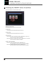
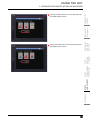
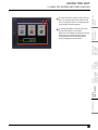
1
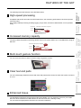
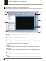
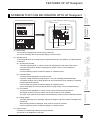
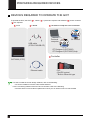
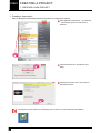
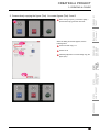
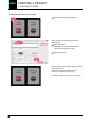
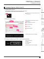
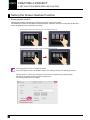
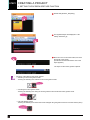
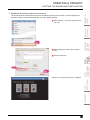
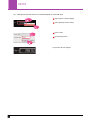
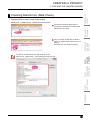
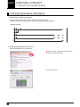
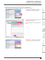
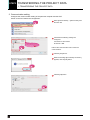
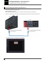
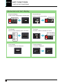
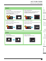
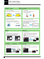
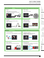
APPENDICES
STEP3
USING THE GOT
STEP2
TRANSFERRING
THE PROJECT
STEP1
CREATING
A PROJECT
PREPARING
REQUIRED
DEVICES
Let's start!
FEATURES OF
GT Designer3
FEATURES OF
THE GOT
Mitsubishi Graphic Operation Terminal
GOT2000 Series Quick Start Guide
G r a p h i c O p e r a t i o n Te r m i n a l
SAFETY PRECAUTIONS
(Always read these instructions before using this product.)
Before designing a system, make sure to read the relevant manuals carefully and handle the product
properly with full attention to safety.
[PRECAUTIONS ON THE PRACTICAL TRAINING IN THIS DOCUMENT]
DANGER
● When power is on, do not touch the terminals not to cause any electric shock accident.
● Before opening the safety cover, power off the system or secure a safe environment.
CAUTION
● When installing or removing a module or unit, power off it in advance.
Doing so while power is on can cause the module or unit to fail or an electric shock.
● When any error or malfunction occurs, stop using the module or unit immediately.
[GOT2000-RELEVANT MANUALS]
For detailed information, refer to each manual of GOT2000.
The GOT2000-relevant manuals can be downloaded from the MITSUBISHI ELECTRIC FA Global Website
(http://www.mitsubishielectric.com/fa/).
* This document uses GT Designer3 (GOT2000) Version 1.117X for explanation.
Depending on the version used, the display of the menu and screens may differ.
INDEX
HOW TO READ MARKS
Refers to information required for operation and precautions.
Refers to useful information.
Introduces reference manuals and pages that describe details.
CONTENTS
FEATURES OF THE GOT
3
1. High-speed processing . . . . . . . . . . . . . . . . . . . . . . . . . . . . . . . . . . . . . . . . . . . . . . . . . . . . . . . . . . . . . . . . . . . 4
2. Increased memory capacity . . . . . . . . . . . . . . . . . . . . . . . . . . . . . . . . . . . . . . . . . . . . . . . . . . . . . . . . . . . . . . . 4
3. Multi-touch gesture function . . . . . . . . . . . . . . . . . . . . . . . . . . . . . . . . . . . . . . . . . . . . . . . . . . . . . . . . . . . . . . . 4
4. Clear text and parts . . . . . . . . . . . . . . . . . . . . . . . . . . . . . . . . . . . . . . . . . . . . . . . . . . . . . . . . . . . . . . . . . . . . . 4
5. Enhanced lineup . . . . . . . . . . . . . . . . . . . . . . . . . . . . . . . . . . . . . . . . . . . . . . . . . . . . . . . . . . . . . . . . . . . . . . . . 4
6. GOT's appearance and enhanced interface . . . . . . . . . . . . . . . . . . . . . . . . . . . . . . . . . . . . . . . . . . . . . . . . . . . 5
FEATURES OF GT Designer3
6
1. SCREEN LAYOUT OF GT Designer3 . . . . . . . . . . . . . . . . . . . . . . . . . . . . . . . . . . . . . . . . . . . . . . . . . . . . . . . 7
2. SCREENS THAT CAN BE CREATED WITH GT Designer3 . . . . . . . . . . . . . . . . . . . . . . . . . . . . . . . . . . . . . . 8
PREPARING REQUIRED DEVICES
9
1. DEVICES REQUIRED TO OPERATE THE GOT . . . . . . . . . . . . . . . . . . . . . . . . . . . . . . . . . . . . . . . . . . . . . . . 9
STEP1 CREATING A PROJECT
10
1. CREATING A NEW PROJECT
10
1-1. Creating a New Project . . . . . . . . . . . . . . . . . . . . . . . . . . . . . . . . . . . . . . . . . . . . . . . . . . . . . . . . . . . . . . . . 10
2. CREATING AN OBJECT
17
2-1. Creating a RUN Switch . . . . . . . . . . . . . . . . . . . . . . . . . . . . . . . . . . . . . . . . . . . . . . . . . . . . . . . . . . . . . . . . 17
2-2. Creating a STOP Switch . . . . . . . . . . . . . . . . . . . . . . . . . . . . . . . . . . . . . . . . . . . . . . . . . . . . . . . . . . . . . . . 21
2-3. Creating a Running Lamp . . . . . . . . . . . . . . . . . . . . . . . . . . . . . . . . . . . . . . . . . . . . . . . . . . . . . . . . . . . . . . 24
2-4. Creating a Numerical Display . . . . . . . . . . . . . . . . . . . . . . . . . . . . . . . . . . . . . . . . . . . . . . . . . . . . . . . . . . . 29
3. CREATING A FIGURE
31
3-1. Creating a Figure (Rectangle). . . . . . . . . . . . . . . . . . . . . . . . . . . . . . . . . . . . . . . . . . . . . . . . . . . . . . . . . . . 31
3-2. Creating Figures (Text) 1 to 3 . . . . . . . . . . . . . . . . . . . . . . . . . . . . . . . . . . . . . . . . . . . . . . . . . . . . . . . . . . . 33
3-3. Creating Figures (Text) 4 and 5 . . . . . . . . . . . . . . . . . . . . . . . . . . . . . . . . . . . . . . . . . . . . . . . . . . . . . . . . . 36
1
INDEX
INDEX
4. SETTING THE SCREEN GESTURE FUNCTION
37
4-1. Setting the Screen Gesture Function . . . . . . . . . . . . . . . . . . . . . . . . . . . . . . . . . . . . . . . . . . . . . . . . . . . . . 37
5. CHECKING THE CREATED SCREEN
41
5-1. Checking the Display (Screen Preview) . . . . . . . . . . . . . . . . . . . . . . . . . . . . . . . . . . . . . . . . . . . . . . . . . . . 41
5-2. Checking Data Errors (Data Check) . . . . . . . . . . . . . . . . . . . . . . . . . . . . . . . . . . . . . . . . . . . . . . . . . . . . . . 44
5-3. Checking Operations (Simulator) . . . . . . . . . . . . . . . . . . . . . . . . . . . . . . . . . . . . . . . . . . . . . . . . . . . . . . . . 45
6. SAVING THE PROJECT
49
6-1. Saving the Project. . . . . . . . . . . . . . . . . . . . . . . . . . . . . . . . . . . . . . . . . . . . . . . . . . . . . . . . . . . . . . . . . . . . 49
STEP2 TRANSFERRING THE PROJECT
50
1. TRANSFERRING THE PROJECT DATA
50
1-1. Transferring the Project Data . . . . . . . . . . . . . . . . . . . . . . . . . . . . . . . . . . . . . . . . . . . . . . . . . . . . . . . . . . . 50
2. CONNECTING THE GOT AND PLC
53
2-1. Connecting the GOT and the PLC . . . . . . . . . . . . . . . . . . . . . . . . . . . . . . . . . . . . . . . . . . . . . . . . . . . . . . . 53
STEP3 USING THE GOT
57
1. CHECKING THE ON/OFF ACTION OF SWITCHES
57
1-1. Checking the ON/OFF action of switches . . . . . . . . . . . . . . . . . . . . . . . . . . . . . . . . . . . . . . . . . . . . . . . . . . 57
2. USING THE SCREEN GESTURE FUNCTION
59
2-1. Using the Screen Gesture Function . . . . . . . . . . . . . . . . . . . . . . . . . . . . . . . . . . . . . . . . . . . . . . . . . . . . . . 59
APPENDIX 1 NEW FUNCTIONS
61
1. UTILIZE DATA FUNCTION . . . . . . . . . . . . . . . . . . . . . . . . . . . . . . . . . . . . . . . . . . . . . . . . . . . . . . . . . . . . . . . 61
2. INPUT ASSIST FUNCTION . . . . . . . . . . . . . . . . . . . . . . . . . . . . . . . . . . . . . . . . . . . . . . . . . . . . . . . . . . . . . . 63
3. HELP . . . . . . . . . . . . . . . . . . . . . . . . . . . . . . . . . . . . . . . . . . . . . . . . . . . . . . . . . . . . . . . . . . . . . . . . . . . . . . . 64
APPENDIX 2 FUNCTION UPDATE
65
1. SCREEN DESIGN SOFTWARE UPDATE . . . . . . . . . . . . . . . . . . . . . . . . . . . . . . . . . . . . . . . . . . . . . . . . . . . 65
APPENDIX 3 GOT FUNCTIONS
66
1. LIST OF GOT FUNCTIONS . . . . . . . . . . . . . . . . . . . . . . . . . . . . . . . . . . . . . . . . . . . . . . . . . . . . . . . . . . . . . . 66
APPENDIX 4 RELEVANT CATALOGS AND MANUALS
71
INDEX
2
FEATURES OF THE GOT
FEATURES OF THE GOT
GOT is the abbreviation of "Graphic Operation Terminal".
Switches and lamps had been conventionally attached to an operation panel as hardware. However, by
using the screen design software, those can be created, and displayed and operated on the monitor screen
of the GOT, the touch-panel HMI.
Conventional
operation panel
GOT
Space
saving
Cost
reduction
Advantages of the GOT
(1) Downsizing the operation panel
Since switches and lamps are created using software, the number of components attached to the
operation panel as hardware can be reduced and the panel itself can be downsized.
(2) Cutting costs for wiring
Wiring between components inside the operation panel is replaced with screen design by software,
eliminating the need for the wiring, which requires a large amount of time and cost.
(3) Standardizing operation panels
Even though required specifications changes, you just need to change settings using software.
Therefore, operation panels can be standardized.
(4) Adding extra values as an HMI (Human Machine Interface)
The GOT can easily display graphics, text, and alarms in addition to switches and lamps.
Therefore, the extra value of your entire equipment can be improved.
3
FEATURES OF THE GOT
FEATURES OF THE GOT
High-speed processing
GT27/GT16
FEATURES OF
GT Designer3
Compared with the GT16 model of the GOT1000 series, the monitoring performance has been improved
more than twice.
Even highly-loaded processing including logging, script, alarm, and device data transfer can be operated
easily.
Monitoring performance comparison
<GT16>
More than
twice
<GT27>
High
2
Monitoring performance
Increased memory capacity
The project data compression technology allows users to use project data of up to 128 MB without using an
SD card.
GT27/GT16 ROM capacity comparison Approx.
9 times
<GT16> 15 MB
PREPARING
REQUIRED
DEVICES
1
FEATURES OF
THE GOT
The following shows the features of the GOT2000 series.
<GT27> 57 MB
3
STEP1
CREATING
A PROJECT
128 MB (Actually storable data size)
Multi-touch gesture function
4
Clear text and parts
5
APPENDICES
You can create highly-attractive screens with fonts and parts that are clear even when the screen is zoomed
in or out.
STEP3
USING THE GOT
STEP2
TRANSFERRING
THE PROJECT
You can scroll and zoom in and out screens using the gesture function.
Enhanced lineup
The standard model (black) and the white model are available. You can select the colors for your needs.
Since the white model has no USB interface on the GOT front face, cleaning is easy.
You can select an appropriate model and use it at various situations.
FEATURES OF THE GOT
4
FEATURES OF THE GOT
6
GOT's appearance and enhanced interface
The following shows the GOT2000's appearance and its enhanced interface.
[Front face]
Human sensor
Simple design
The GOT detects an operator and
displays its screen automatically.
When no one is around,
the backlight turns off to
save energy.
The stylish and simple design with
a linear motif is sleek and
complements any machine design.
* GT27 (15" and 12.1" only)
USB device
Data can be transferred without
opening the cabinet.
* The USB device is on the rear face for the
white model and GT21.
USB host
LED backlight
Screen data can be transferred
and data in the GOT can be
retrieved using a USB memory.
A USB mouse and keyboard
can be connected.
The long life cycle minimizes
maintenance and replacement costs.
* GT27 and GT25 only. The USB host is on
the rear face for the white model.
[Rear face]
SD card slot
Extension interface
A large amount of data including
alarms and logging data
can be saved.
Communication and option units
can be mounted.
* GT27 and GT25 only
Ethernet
Side interface
Up to four types of PLCs from
different manufacturers* can be
connected simultaneously
by Ethernet.
* Up to two types of PLCs for GT21
RS-232
USB host
Various FA devices, barcode reader,
serial printer can be connected.
RS-422/485
* This image is GT2712.
Various FA devices can be
connected.
USB device
The GOT can be connected
to a personal computer
to transfer data.
* White model only
5
FEATURES OF THE GOT
A USB memory can be mounted
to save alarms and logging data.
A USB mouse and keyboard can
be connected.
* GT27 and GT25 only
FEATURES OF GT Designer3
FEATURES OF GT Designer3
FEATURES OF
THE GOT
GT Designer3 is the software to create screens for the GOT2000 series and the GOT1000 series.
This software enables you to create and simulate a project, and transfer data between the GOT and a
personal computer.
Project creation
simulation
Personal computer (GT Designer3)
FEATURES OF
GT Designer3
Data transfer
GOT
GT Designer3 consists of the following screen design software.
• GT Designer3 (GOT2000): Screen design software for GOT2000 series
• GT Designer3 (GOT1000): Screen design software for GOT1000 series
This document describes creating a screen for GOT2000 with GT Designer3 (GOT2000).
APPENDICES
STEP3
USING THE GOT
STEP2
TRANSFERRING
THE PROJECT
STEP1
CREATING
A PROJECT
PREPARING
REQUIRED
DEVICES
Screen image of GT Designer3 (GOT2000)
FEATURES OF GT Designer3
6
FEATURES OF GT Designer3
SCREEN LAYOUT OF GT Designer3
1
The following shows the screen layout of GT Designer3.
1
5
2
4
3
3
4
6
7
3
7
8
1
Title bar
Displays the software name, a project name, and a file name.
2
Menu bar
GT Designer3 can be operated from pull-down menus.
3
Toolbar
GT Designer3 can be operated by buttons. You can place the toolbar on the left, right, top, or bottom.
4
Docking window
Windows that can be docked with the screen of GT Designer3.
5
Editor tab
Displays the tabs of the windows and screen editors which are displayed on the work window.
6
Work window
Displays screen editors, the [Environmental Setting] window, the [GOT Setup] window, and other
windows.
7
Screen editor
Creates a screen to be displayed on the GOT by placing figures and objects on the screen editor.
8
Status bar
Displays information according to the position of the mouse cursor, the status of a selected figure or
object.
FEATURES OF GT Designer3
SCREENS THAT CAN BE CREATED WITH GT Designer3
Base screen
Screen displayed on the GOT
Overlap window
Superimpose window
Production status screen 1
FEATURES OF
GT Designer3
A1254 B 348
Production status screen 1
A1254 B 348
PREPARING
REQUIRED
DEVICES
Window screen
Key window
Dialog window
Base screen
STEP1
CREATING
A PROJECT
(1) Base screen
A screen that is displayed as a base screen of the GOT.
The screen switching device controls the display of a base screen.
(2) Window screen
A screen displayed as an overlap window, superimpose window, key window, and dialog window
on the GOT.
STEP2
TRANSFERRING
THE PROJECT
(a) Superimpose window
A window superimposed on a base screen and displayed as a part of the base screen.
Up to two superimpose windows (superimpose window 1 and 2) can be displayed
simultaneously.
A screen switching device controls the display of a window screen.
(b) Overlap window
A pop-up window displayed over a base screen.
Up to five overlap windows (overlap window 1 to 5) can be displayed simultaneously.
The display position of an overlap window can be moved with a touch operation or a display
position specification device.
A screen switching device controls the display of a window screen.
(GT21 can display up to two overlap windows (overlap window 1 and 2) simultaneously.)
(c) Key window
A pop-up window displayed on a base screen for the numerical input and others.
The display position of the key window can be moved with a touch operation.
Two types of key windows are provided: GOT standard key window and user-created key window.
(d) Dialog window
A window displaying error messages, warning messages, and GOT system messages in the
foreground.
While a dialog window is displayed, other screens cannot be operated.
A screen switching device controls the display of a window screen.
(3) Report screen
A window for outputting the data by the report function.
This screen is not displayed on the GOT.
FEATURES OF GT Designer3
8
STEP3
USING THE GOT
Screens created with GT Designer3
APPENDICES
2
FEATURES OF
THE GOT
FEATURES OF GT Designer3
PREPARING REQUIRED DEVICES
PREPARING REQUIRED DEVICES
1
DEVICES REQUIRED TO OPERATE THE GOT
To operate the GOT, the GOT ( 1 ), cables ( 2 ), a personal computer and software ( 3 ), and a controller
( 4 ) are required.
1
GOT
2
Cable
3
Personal computer and software
Personal
computer
USB cable
(GT09-C30USB-5P)
GX Works2
MODEL SW1DND-GTWK3-J
COPYRIGHT(C)2009
MITSUBISHI ELECTRIC CORPORATION
ALL RIGHTS RESERVED
GT Designer3 (GOT2000)
GT Designer3 (GOT2000) Help
4
Controller
GOT2000 (GT27)
Ethernet cable
PLC
(QnUDV series)
* Built-in Ethernet type
For how to install the screen design software, refer to the following.
• GT Works3 Installation Instructions BCN-P5999-0066/0071
For the connecting method of the GOT and a controller, refer to the following.
• GOT2000 Series Connection Manual (Mitsubishi Products) For GT Works3 Version1 SH-081197ENG
9
PREPARING REQUIRED DEVICES
STEP1
CREATING A PROJECT
1. CREATING A NEW PROJECT
STEP1 CREATING A PROJECT
1. CREATING A NEW PROJECT
FEATURES OF
THE GOT
Creating a New Project
FEATURES OF
GT Designer3
The following screen is created in this document.
(6)
(5)
(1)
PREPARING
REQUIRED
DEVICES
(4)
(2)
STEP1
CREATING
A PROJECT
(3)
STEP2
TRANSFERRING
THE PROJECT
(1) RUN switch, STOP switch
Touch each switch to turn on or off a bit device of the PLC.
➠ 2-1 Creating a RUN Switch
➠ 2-2 Creating a STOP Switch
(2) Running lamp
Turns on or off according to the status of the bit device of the PLC.
STEP3
USING THE GOT
➠ 2-3 Creating a Running Lamp
(3) Numerical display
Displays the value stored in the PLC.
➠ 2-4 Creating a Numerical Display
(4) Figure (Rectangle)
Place rectangles to make switches and lamps more visible.
➠ 3-1 Creating a Figure (Rectangle)
APPENDICES
1-1
(5) Figure (Text) 1) to 5)
Characters that describe screens, switches, and lamps are displayed.
➠ 3-2 Creating Figures (Text) 1 to 3
➠ 3-3 Creating Figures (Text) 4 and 5
(6) Screen gesture switch
Pinch in the screen to zoom out the screen and pinch out the screen to zoom in the screen with this
switch.
➠ 4-1 Setting the Screen Gesture Function
1. CREATING A NEW PROJECT
10
STEP1
CREATING A PROJECT
1. CREATING A NEW PROJECT
1. Creating a new project
Start GT Designer3 (GOT2000) and follow the wizard to configure the settings.
1 Select [MELSOFT Application] → [GT Works3]
→ [GT Designer3] from the start menu of
Windows.
Click!
1
2 Click the [New] button in the Select Project
Click!
2
dialog.
3 Click the [Next] button on the start screen of
New Project Wizard.
Click!
3
GT Designer3 can be started from the desktop when a shortcut icon was created at the installation.
11 1. CREATING A NEW PROJECT
CREATING A PROJECT
FEATURES OF
THE GOT
1. CREATING A NEW PROJECT
4 Check the settings on the system setting
window and click the [Next] button.
• Series: GOT2000
• GOT Type: GT27**-V (640×480)
• Use the gesture function: Selected
• Standard Language: English
FEATURES OF
GT Designer3
• Outline Font
Alphanumeric/Kana: Selected
Kanji: Cleared
Hangul: Cleared
Click!
PREPARING
REQUIRED
DEVICES
4
5 Check the displayed settings and click the
Click!
5
6 Select [MELSEC-Q/QS, Q17nD/M/NC/DR,
CRnD-700] in a drop-down list of [Controller
Type] on the communication settings window.
6
7 Click the [Next] button.
STEP3
USING THE GOT
Select
STEP2
TRANSFERRING
THE PROJECT
STEP1
CREATING
A PROJECT
[Next] button.
Click!
APPENDICES
7
1. CREATING A NEW PROJECT
12
STEP1
CREATING A PROJECT
1. CREATING A NEW PROJECT
8 Select [Standard(Ethernet):Multi] in a drop-
down list of [I/F].
Select
9 Click the [Next] button.
8
Click!
9
10 Check the communication driver setting and
Click!
10
click the [Detail Setting] button.
Communication Driver: Ethernet(MELSEC),
Q17nNC, CRnD-700, Gateway
11 The window shown left appears. Change the
value of [GOT Station].
GOT Station: 2
Click!
12 Click the [OK] button.
11
Click!
12
Click the [GOT Standard Ethernet Setting] button to change the IP address of the GOT.
13 1. CREATING A NEW PROJECT
CREATING A PROJECT
FEATURES OF
THE GOT
1. CREATING A NEW PROJECT
FEATURES OF
GT Designer3
13 Click the [Next] button.
Click!
13
14 Check the displayed settings and click the
PREPARING
REQUIRED
DEVICES
[Next] button.
STEP1
CREATING
A PROJECT
Click!
14
15 Check the screen switching devices of the
STEP2
TRANSFERRING
THE PROJECT
base screen and click the [Next] button.
Base Screen: GD100 (Default)
STEP3
USING THE GOT
Click!
APPENDICES
15
1. CREATING A NEW PROJECT
14
STEP1
CREATING A PROJECT
1. CREATING A NEW PROJECT
16 Check the settings with the wizard then click
the [Finish] button.
Click!
16
The editing screen of GT Designer3 (GOT2000) appears, and the base screen 1 is created.
15 1. CREATING A NEW PROJECT
FEATURES OF
THE GOT
HINTS1.?????????????
When GT Designer3 (GOT1000) is started
GT Designer3 starts the screen design software that was used to save a project last time.
When GT Designer3 (GOT1000) is started, start the screen design software for GOT2000 by either of
the following methods.
STEP2
TRANSFERRING
THE PROJECT
STEP1
CREATING
A PROJECT
(1) Starting GT Designer3 (GOT2000) from the menu
Select [Project] → [Start GT Designer3 (GOT2000)] from the menu bar to start GT Designer3
(GOT2000).
PREPARING
REQUIRED
DEVICES
FEATURES OF
GT Designer3
When the screen design software for GOT1000 is started
APPENDICES
STEP3
USING THE GOT
(2) Starting GT Designer3 (GOT2000) from the wizard
Select [GOT2000] for [Series] on the [New Project Wizard] dialog to start GT Designer3
(GOT2000).
1. CREATING A NEW PROJECT
16
CREATING A PROJECT
STEP1
2. CREATING AN OBJECT
2. CREATING AN OBJECT
2-1
Creating a RUN Switch
1. Placing a switch
Select [Object] → [Switch] → [Bit Switch] from the menu bar to place a switch.
You can select the item from the toolbar as well.
Placing an object
When an object is selected from the menu or the toolbar, the shape of the cursor changes to "+".
Click any area where the object is to be placed on a screen editor.
Click
Place
The object can be placed in any size when placing it by dragging the cursor.
Drag
17
2. CREATING AN OBJECT
Place
CREATING A PROJECT
2. CREATING AN OBJECT
FEATURES OF
THE GOT
2. Setting a device and action
1 Double-click the placed switch.
Doubleclick!
FEATURES OF
GT Designer3
1
When the dialog shown left appears, set the
following items.
2 Device: M0
PREPARING
REQUIRED
DEVICES
Action: Momentary
Set "Device: M0" and
"Action: Momentary".
STEP2
TRANSFERRING
THE PROJECT
STEP1
CREATING
A PROJECT
2
Setting a device
to set a device.
STEP3
USING THE GOT
Click the
APPENDICES
Click!
The device can also be set by entering it directly using a keyboard.
Directly enter
a device and
press the Enter
key.
2. CREATING AN OBJECT
18
STEP1
CREATING A PROJECT
2. CREATING AN OBJECT
3. Setting text
3 Select the Text tab.
Click!
3
4 Enter "RUN" in Text.
5 Click the [OK] button.
Enter "RUN"
in Text.
4
Click!
5
Creating the RUN switch is completed.
When you have any question, press the F1 key to start the GT Designer3 (GOT2000) help. The help
page appropriate for the operation that you are doing is displayed.
For the GT Designer3 (GOT2000) help, refer to the following.
➠ APPENDIX 1.3 HELP
19 2. CREATING AN OBJECT
FEATURES OF
THE GOT
HINTS1.?????????????
Bit switch actions
A bit switch turns on and off the bit device specified by the switch.
The following shows the actions that can be set with bit switches.
X0001: OFF
X0001: ON
X0001: OFF
X0001: ON
X0001: OFF
STOP
RUN
STOP
RUN
STOP
FEATURES OF
GT Designer3
(1) Bit momentary
Keeps a specified bit device on only while you touch the switch.
X0001: ON
X0001: ON
X0001: ON
X0001: OFF
X0001: OFF
STOP
RUN
RUN
RUN
STOP
STOP
STEP1
CREATING
A PROJECT
X0001: OFF
PREPARING
REQUIRED
DEVICES
(2) Bit alternate
Alternates the status of a specified bit device (ON←→OFF) when you touch the switch.
(3) Bit set
Turns on a specified bit device when you touch the switch.
X0001: ON
X0001: ON
X0001: ON
X0001: ON
X0001: ON
STOP
RUN
RUN
RUN
RUN
RUN
STEP2
TRANSFERRING
THE PROJECT
X0001: OFF
X0001: OFF
X0001: OFF
X0001: OFF
X0001: OFF
X0001: OFF
RUN
STOP
STOP
STOP
STOP
STOP
APPENDICES
X0001: ON
STEP3
USING THE GOT
(4) Bit reset
Turns off a specified bit device when you touch the switch.
2. CREATING AN OBJECT
20
STEP1
CREATING A PROJECT
2. CREATING AN OBJECT
2-2
Creating a STOP Switch
1. Copying the RUN switch
1 Select the RUN switch.
Click!
1
2 Drag the switch while pressing the Ctrl key.
Drag the switch
while pressing
the Ctrl key.
2
2. Changing the device of the copy of the RUN switch
Doubleclick!
3 Double-click the copied RUN switch.
3
4 When the dialog shown left appears, change
the device as follows.
Device: M0 → M1
Change the device
from "M0" to "M1".
21 2. CREATING AN OBJECT
4
CREATING A PROJECT
2. CREATING AN OBJECT
FEATURES OF
THE GOT
3. Changing the shape color of the switch
5 Select the Style tab.
Click!
5
6 Select the shape of the off status.
7 Select a shape color.
Click!
Click!
8 Select the shape of the on status.
8
6
FEATURES OF
GT Designer3
Blue → Red
Change the color from
"Blue" to "Red".
9 Select a shape color.
Blue → Red
PREPARING
REQUIRED
DEVICES
7 9
STEP1
CREATING
A PROJECT
4. Changing the text of the switch
10 Select the Text tab.
Click!
10
STEP2
TRANSFERRING
THE PROJECT
11 Enter "STOP" in Text.
12 Click the [OK] button.
Change the text
from "RUN" to
"STOP".
STEP3
USING THE GOT
11
Click!
APPENDICES
12
Creating the STOP switch is completed.
2. CREATING AN OBJECT
22
HINTS1.?????????????
Property sheet
The property sheet displays the list of attributes and set values of a selected screen, figure, or object.
Settings can be checked or changed without opening the setting dialog.
Set values can be changed collectively by selecting multiple figures or objects on the same screen.
Changing devices
Changing shape colors
Changing text
For how to display the property sheet and how to set each item, refer to the help or the GT Designer3
(GOT2000) Screen Design Manual.
23 2. CREATING AN OBJECT
CREATING A PROJECT
2. CREATING AN OBJECT
Creating a Running Lamp
FEATURES OF
THE GOT
2-3
1. Placing a lamp
Select [Object] → [Lamp] → [Bit Lamp] from the menu bar to place a lamp.
FEATURES OF
GT Designer3
You can select the item from the toolbar as well.
2. Setting a device, shape, and color for the lamp
PREPARING
REQUIRED
DEVICES
1 Double-click the placed lamp.
Doubleclick!
STEP1
CREATING
A PROJECT
1
When the dialog shown left appears, set the
following items.
Set "Y0010".
2 Device: Y0010
2
Click!
STEP2
TRANSFERRING
THE PROJECT
3 Select the shape of the off status.
4 Select a shape color.
3
Red → Green
Click!
6 Select a shape color.
Red → Green
APPENDICES
Change the color from
"Red" to "Green". 4 6
STEP3
USING THE GOT
5 Select the shape of the on status.
5
2. CREATING AN OBJECT
24
STEP1
CREATING A PROJECT
2. CREATING AN OBJECT
3. Setting text for the lamp
7 Select the Text tab.
Click!
7
8 Select the shape of the off status.
9 Text Size: Select 12 dots.
Click!
8
10 Enter "STOP" in Text.
Enter
"STOP". 10
Select
"12".
9
Click!
11 Clear the check box for "OFF=ON".
11
12 Select the shape of the on status.
Click!
12
Select
"Black". 13
Enter
"STOP". 14
13 Select black for Text Color.
14 Enter "RUN" in Text.
15 Click the [OK] button.
Click!
15
Creating the running lamp is completed.
25 2. CREATING AN OBJECT
FEATURES OF
THE GOT
HINTS1.?????????????
Display of objects on the screen editor
The status of objects to be displayed on the screen editor and the display or non-display of set
information can be switched.
(1) Switching the status of objects to be displayed on the screen editor
State No.0
State No.1
State No.63
(2) Setting information to be displayed on the screen editor
(a) Device
Select [View] → [Display Items] → [Device] from the menu to switch between displaying and
hiding devices on the screen editor.
APPENDICES
(b) System label device
Select [View] → [Display Items] → [Device of System Label] from the menu to switch between
displaying and hiding devices assigned to system labels on the screen editor.
STEP3
USING THE GOT
•••
STEP2
TRANSFERRING
THE PROJECT
STEP1
CREATING
A PROJECT
(b) Switching the status by specifying a state No.
Select [View] → [State No.] → [Previous State] or [Next State] from the menu to change display
of the objects on the screen editor according to the state No.
If the status of an object is switched between ON and OFF, the display of the object switches
between OFF with state No.0 and ON with state No.1 or more.
PREPARING
REQUIRED
DEVICES
FEATURES OF
GT Designer3
(a) Switching the status between ON and OFF
Select [View] → [Switch ON/OFF Display] from the menu to switch between the on status
image and off status image of each object on the screen editor.
If a state is set to an object, the display of the object switches between OFF with state No.0
and ON with state No.1.
2. CREATING AN OBJECT
26
HINTS1.?????????????
(c) Object ID
Select [View] → [Display Items] → [Object ID] from the menu to switch between displaying and
hiding object IDs on the screen editor.
(d) Paint
Select [View] → [Display Items] → [Paint] from the menu to switch between displaying and
hiding paints on the screen editor.
(e) Object
Select [View] → [Display Items] → [Object] from the menu to switch between displaying and
hiding objects on the screen editor.
(f)
Object frame
Select [View] → [Display Items] → [Object Frame] from the menu to switch between displaying
and hiding object frames on the screen editor.
(g) Template information
Select [View] → [Display Items] → [Template Information] from the menu to switch between
displaying and hiding template information on the screen editor.
27 2. CREATING AN OBJECT
2.???????????
Option
Select [View] → [Display Items] → [Option] from the menu to display the [Option] dialog.
In this dialog, you can configure the settings displayed on the screen editor.
For the details of the option, refer to the help or the GT Designer3 (GOT2000) Screen Design
Manual.
STEP3
USING THE GOT
Operations using the toolbar
The display of objects can be switched using the [View] toolbar as well.
State No.
Device
Object ID
System label device
APPENDICES
ON/OFF display switching
STEP2
TRANSFERRING
THE PROJECT
STEP1
CREATING
A PROJECT
PREPARING
REQUIRED
DEVICES
(i)
FEATURES OF
GT Designer3
(h) Touch area
Select [View] → [Display Items] → [Touch Area] from the menu to switch between displaying
and hiding touch areas on the screen editor.
FEATURES OF
THE GOT
HINTS
2. CREATING AN OBJECT
28
STEP1
CREATING A PROJECT
2. CREATING AN OBJECT
2-4
Creating a Numerical Display
1. Placing a numerical display
Select [Object] → [Numerical Display/Input] → [Numerical Display] from the menu bar to place a numerical
display.
You can select the item from the toolbar as well.
2. Setting a device and number size for the numerical display
1 Double-click the placed numerical display.
Doubleclick!
1
When the dialog shown left appears, set the
following items.
Set "D10".
2 Device: D10
2
3 Number Size: Select 36 dots.
Select
"36". 3
29 2. CREATING AN OBJECT
CREATING A PROJECT
3. Setting a shape and frame color for the numerical display
4 Select the Style tab.
Click!
4
5 Select "Square_3D_Fixed Width : Rect_12" for
Shape.
FEATURES OF
GT Designer3
Select "Square_3D_Fixed
Width : Rect_12".
FEATURES OF
THE GOT
2. CREATING AN OBJECT
PREPARING
REQUIRED
DEVICES
5
STEP1
CREATING
A PROJECT
6 Select gray for Frame Color.
7 Click the [OK] button.
STEP2
TRANSFERRING
THE PROJECT
6
STEP3
USING THE GOT
Select
"Gray".
Click!
7
2. CREATING AN OBJECT
APPENDICES
Creating the numerical display is completed.
30
STEP1
CREATING A PROJECT
3. CREATING A FIGURE
3. CREATING A FIGURE
3-1
Creating a Figure (Rectangle)
1. Placing a rectangle
Select [Figure] → [Rectangle] from the menu bar to place a rectangle.
You can select the item from the toolbar as well.
1 Drag the mouse from the start point to the end
Start point
point while clicking the mouse.
2 Double-click the rectangle.
Click!
1
Doubleclick!
2
End point
2. Changing the setting of the rectangle
Select
"Pattern: □ 8",
"Shape Color: Gray",
"Type: Rounded",
and "Radius: 5".
3
When the dialog shown left appears, set the
following items.
3 Pattern: □ 8
Shape Color: Gray
Type: Rounded
Radius: 5 dots
4 Click the [OK] button.
Click!
4
Creating the rectangle is completed.
31 3. CREATING A FIGURE
CREATING A PROJECT
3. CREATING A FIGURE
FEATURES OF
THE GOT
3. Consecutively copying the rectangle
5 Select the rectangle and select [Edit] →
Select
Set "3".
6
FEATURES OF
GT Designer3
[Consecutive Copy] from the menu bar.
5
When the dialog shown left appears, set the
following items.
7 Interval: X 30
Set "30".
7
8 Click the [OK] button to consecutively copy the
STEP1
CREATING
A PROJECT
rectangle.
PREPARING
REQUIRED
DEVICES
6 Total count after copy: X 3
Click!
STEP3
USING THE GOT
STEP2
TRANSFERRING
THE PROJECT
8
APPENDICES
The figures are placed on the back layer of the objects.
3. CREATING A FIGURE
32
STEP1
CREATING A PROJECT
3. CREATING A FIGURE
3-2
Creating Figures (Text) 1 to 3
1. Placing a figure (Text) 1
Select [Figure] → [Text] from the menu bar to place a figure (Text).
You can select the item from the toolbar as well.
1 Click the mouse on the area where the text is
Click!
to be entered.
1
2. Setting the figure (Text) 1
When the dialog shown left appears, set the
following items.
Enter "RUN
switch". 2
2 Text: RUN switch
Select
"Black".
(A line feed can be inserted after the text
"RUN" by pressing the Enter key.)
3
Click!
4
3 Text Color: Black
4 Alignment: Center
Click!
5
5 Click the [OK] button.
Creating the figure (Text) 1) is completed.
33 3. CREATING A FIGURE
CREATING A PROJECT
3. Consecutively copying the figure (Text) 1 to create figures (Text) 2 and 3
6 Select the figure (Text) 1) and select [Edit] →
Set "3".
FEATURES OF
GT Designer3
[Consecutive Copy] from the menu bar.
6
When the dialog shown left appears, set the
following items.
7
7 Total count after copy: X 3
8 Interval: X 95
Set "95".
8
9 Click the [OK] button to consecutively copy the
PREPARING
REQUIRED
DEVICES
Select
FEATURES OF
THE GOT
3. CREATING A FIGURE
STEP2
TRANSFERRING
THE PROJECT
STEP1
CREATING
A PROJECT
figure (Text).
Click!
APPENDICES
STEP3
USING THE GOT
9
3. CREATING A FIGURE
34
STEP1
CREATING A PROJECT
3. CREATING A FIGURE
4. Modifying the text of the copies
10 Double-click the copied figure (Text) 2.
Doubleclick!
10
When the dialog shown left appears, set the
following item.
Enter "STOP
switch".
11
11 Text: STOP switch
(A line feed can be inserted after the text
"STOP" by pressing the Enter key.)
12 Click the [OK] button.
Click!
12
Modify the figure (Text) 3 with the same procedure.
Text: Running lamp
(A line feed can be inserted after the text
"Running" by pressing the Enter key.)
Creating the figures (Text) 2 and 3 is completed.
35 3. CREATING A FIGURE
CREATING A PROJECT
3. CREATING A FIGURE
Creating Figures (Text) 4 and 5
FEATURES OF
THE GOT
3-3
1. Placing a figure (Text) 4
Select [Figure] → [Text] from the menu bar to place a figure (Text).
You can select the figure (Text) from the toolbar as well.
1
FEATURES OF
GT Designer3
1 Click the mouse on the area where the text is
Click!
to be entered.
2. Setting the figure (Text) 4
PREPARING
REQUIRED
DEVICES
When the dialog shown left appears, set the
following items.
Enter "Operation
control panel". 2
2 Text: Operation control panel
3 Font: Outline Kaisho
Select "Outline
Kaisho".
4 Size: 36 dots
3
4
STEP1
CREATING
A PROJECT
Select "36".
5 Click the [OK] button.
Click!
STEP2
TRANSFERRING
THE PROJECT
5
Creating the figure (Text) 4 is completed.
STEP3
USING THE GOT
3. Placing and setting a figure (Text) 5 with the same procedure
Set the following items.
Text: Data 1
Font: Outline Gothic
Size: 16 dots
APPENDICES
Creating the figure (Text) 5 is completed.
3. CREATING A FIGURE
36
STEP1
CREATING A PROJECT
4. SETTING THE SCREEN GESTURE FUNCTION
4. SETTING THE SCREEN GESTURE FUNCTION
4-1
Setting the Screen Gesture Function
1. Screen gesture function
This function enables zooming and scrolling the monitor screen of the GOT.
The displayed contents of the objects can be scrolled or zoomed in and out touching directly the GOT
screen by gestures such as pinching out and in.
(Example) Pinching out the screen to zoom in the displayed contents
(Example) Pinching in the screen to zoom out the displayed contents
The screen gesture function is enabled by default.
If the screen gesture function is disabled, configure the setting according to the following procedure.
Select [Common] → [GOT Type Setting] from the menu bar to display the Type Setting dialog.
Select [Use the gesture function] and click the [OK] button.
The screen gesture function is enabled.
Click!
37 4. SETTING THE SCREEN GESTURE FUNCTION
CREATING A PROJECT
2. Creating an object for the screen gesture
Place the switch for switching to the screen gesture mode.
1 Select [View] → [Docking Window] → [Library
Click!
1
2 Click the
Click!
icon on the [Library List] window.
3 Select [System Library] → [Search By
STEP3
USING THE GOT
Function] → [Gesture] from the displayed pulldown menu.
STEP2
TRANSFERRING
THE PROJECT
STEP1
CREATING
A PROJECT
2
PREPARING
REQUIRED
DEVICES
FEATURES OF
GT Designer3
List] from the menu bar.
FEATURES OF
THE GOT
4. SETTING THE SCREEN GESTURE FUNCTION
Click!
APPENDICES
3
4. SETTING THE SCREEN GESTURE FUNCTION
38
STEP1
CREATING A PROJECT
4. SETTING THE SCREEN GESTURE FUNCTION
4 Double-click [Gesture_Title(VGA)].
Doubleclick!
4
5 The registered styles are displayed in a list.
Click [1 Gesture01_B].
Click!
5
6 Move the cursor to the screen editor, and click
Click!
6
the top left of the screen.
(The broken line that indicates the size of the
object appears.)
The object for the screen gesture is placed.
Functions of the object for the screen gesture
• Switching to the screen gesture mode
Touching the following icon switches to the screen gesture mode.
Touch to switch
the mode.
• Canceling the screen gesture mode
Touching the following icon during the screen gesture mode cancels the screen gesture mode.
Touch to cancel
the mode.
• Full scale display (100%)
Touching the following icon resizes the screen enlarged using the gesture function to the actual size (100%).
Touch to change
the display to full
scale display.
39 4. SETTING THE SCREEN GESTURE FUNCTION
CREATING A PROJECT
4. SETTING THE SCREEN GESTURE FUNCTION
The screen gesture inactive area, the area for 32 dots from the top of the screen, is not the target to be
zoomed in and out and scrolled during the use of the gesture function.
7 Select [Screen] → [Screen Property] from the
FEATURES OF
GT Designer3
menu bar.
FEATURES OF
THE GOT
3. Displaying the screen gesture inactive area
Click!
PREPARING
REQUIRED
DEVICES
7
8 Select [Display the screen gesture inactive
area].
STEP2
TRANSFERRING
THE PROJECT
8
Click!
9
STEP3
USING THE GOT
Setting the screen gesture function is completed.
APPENDICES
Check
STEP1
CREATING
A PROJECT
9 Click the [OK] button.
4. SETTING THE SCREEN GESTURE FUNCTION
40
STEP1
CREATING A PROJECT
5. CHECKING THE CREATED SCREEN
5. CHECKING THE CREATED SCREEN
5-1
Checking the Display (Screen Preview)
1. Checking the display state of on and off of the created screen and objects
Select [View] → [Preview] from the menu bar.
1 The Screen Preview window appears. Click the
Click!
[ON] button.
1
2 The shapes of the objects are switched to the
Click!
3
shapes of the on status.
3 Clicking the [OFF] button displays the shapes
of the off status.
The shapes of the
on status are
displayed. 2
41 5. CHECKING THE CREATED SCREEN
FEATURES OF
THE GOT
HINTS1.?????????????
Checking the display of lamps and switches by each object
On the Screen Preview window, the display of lamps and switches can be switched to check each
display.
(1) Switching the ON/OFF status
FEATURES OF
GT Designer3
1 Right-click an object.
2 Select [ON] or [OFF].
Right-click!
Click!
2
STEP3
USING THE GOT
Shape of off status
APPENDICES
Shape of on status
STEP2
TRANSFERRING
THE PROJECT
The shape of the on status or the one of the off
status is displayed.
STEP1
CREATING
A PROJECT
PREPARING
REQUIRED
DEVICES
1
5. CHECKING THE CREATED SCREEN
42
HINTS1.?????????????
(2) Changing the preview value of a numerical display or numerical input
1 Right-click the numerical display.
Right-click!
1
2 Select [Change Preview Value].
Click!
2
Enter a
value. 3
3 Enter a value.
4 Click the [OK] button.
Click!
4
The preview value is changed.
43 5. CHECKING THE CREATED SCREEN
CREATING A PROJECT
5. CHECKING THE CREATED SCREEN
FEATURES OF
THE GOT
Checking Data Errors (Data Check)
1. Checking that no error exists in the project
Select [Tool] → [Data Check] → [Check] from the menu bar.
1 Check that the message [Data Check is
Completion
display
FEATURES OF
GT Designer3
completed.] is displayed on the Data Check
widow and no error exists.
1
2 If any error exists, double-click the result to
jump to the position which causes an error or
warning.
Check the error and change the setting.
Doubleclick!
2
STEP2
TRANSFERRING
THE PROJECT
STEP1
CREATING
A PROJECT
The items to be checked with the data check can be set.
Select [Tool] → [Data Check] → [Item Setting] from the menu bar.
PREPARING
REQUIRED
DEVICES
5-2
APPENDICES
STEP3
USING THE GOT
Select the
check items.
5. CHECKING THE CREATED SCREEN
44
STEP1
CREATING A PROJECT
5. CHECKING THE CREATED SCREEN
5-3
Checking Operations (Simulator)
1. Preparing a sequence program
Prepare a sequence program for the simulation using simulators.
To proceed to the next step, create a sequence program using GX Works2.
<Sample program>
2. Starting the simulator for the PLC
Start GX Simulator2 from GX Works2.
1 Select [Debug] → [Start/Stop Simulation] from
the menu bar of GX Works2.
Click!
1
GX Simulator2 starts.
45 5. CHECKING THE CREATED SCREEN
CREATING A PROJECT
3. Starting the simulator for the GOT to check the created screen
Start GT Simulator3 from GT Designer3 (GOT2000) to check the created screen.
2 Select [Tools] → [Simulator] → [Set] from the
menu bar of GT Designer3 (GOT2000).
FEATURES OF
GT Designer3
Click!
FEATURES OF
THE GOT
5. CHECKING THE CREATED SCREEN
2
Simulator2 for Connection.
3
4 Click the [OK] button to complete the settings.
Click!
4
5 Select [Tools] → [Simulator] → [Activate] from
the menu bar of GT Designer3 (GOT2000).
Click!
APPENDICES
5
STEP3
USING THE GOT
STEP2
TRANSFERRING
THE PROJECT
STEP1
CREATING
A PROJECT
Select
"GX Simulator2".
PREPARING
REQUIRED
DEVICES
3 When the dialog shown left appears, select GX
5. CHECKING THE CREATED SCREEN
46
CREATING A PROJECT
STEP1
5. CHECKING THE CREATED SCREEN
The simulator starts, and the created screen can
be simulated.
6 Click the RUN button.
7 The Running lamp turns on and the value of
Data 1 changes to 6666.
Click!
6
The lamp turns on
and the value
changes to 6666.
7
The simulator can be started, updated, and exited from the toolbar of GT Designer3.
(1)
(2)
(3)
(4)
(1) [Simulator: Activate]
Activates GT Simulator3 to start the simulation.
(2) [Simulator: Update]
Updates the project in simulation with the project being edited.
The changes made by using GT Designer3 can be reflected to the project in simulation.
(3) [Simulator: Set]
Opens the setting window of the simulator.
(4) [Simulator: End]
Exits GT Simulator3.
47 5. CHECKING THE CREATED SCREEN
CREATING A PROJECT
FEATURES OF
THE GOT
5. CHECKING THE CREATED SCREEN
8 Click the STOP button.
9 The Running lamp turns off and the value of
FEATURES OF
GT Designer3
Data 1 changes to 3333.
Click!
8
9
PREPARING
REQUIRED
DEVICES
The lamp turns off
and the value
changes to 3333.
4. Exiting the simulator for the GOT
Exit GT Simulator3 after the simulation.
10 Select [Tools] → [Simulator] → [Exit] from the
STEP1
CREATING
A PROJECT
menu bar of GT Designer3 (GOT2000).
Click!
5. Exiting the simulator for the PLC
Exit GX Simulator2 of GX Works2.
11 Select [Debug] → [Start/Stop Simulation] from
the menu bar of GX Works2.
Click!
APPENDICES
11
STEP3
USING THE GOT
STEP2
TRANSFERRING
THE PROJECT
10
5. CHECKING THE CREATED SCREEN
48
CREATING A PROJECT
STEP1
6. SAVING THE PROJECT
6. SAVING THE PROJECT
6-1
Saving the Project
1. Saving the created screen
1 Select [Project] → [Save As] from the menu
bar.
Click!
1
2 Enter a file name and click the [Save] button to
save the screen.
Enter a file name and
click the Save button.
2
2. Type of files
A project can be saved in the following formats.
• Workspace format
• Single file format (*.GTX)
• Single file format (*.GTXS) with system applications
This document explains about a single file format (*.GTX) project.
For the details of each format, refer to the help or the GT Designer3 (GOT2000) Screen Design Manual.
49 6. SAVING THE PROJECT
STEP2
TRANSFERRING THE PROJECT DATA
1. TRANSFERRING THE PROJECT DATA
STEP2 TRANSFERRING THE PROJECT
1. TRANSFERRING THE PROJECT DATA
FEATURES OF
THE GOT
Transferring the Project Data
1. Connecting the personal computer to the GOT
Use a USB cable to connect the personal computer to the GOT.
FEATURES OF
GT Designer3
Personal computer
USB cable
(GT09-C30USB-5P)
GOT
PREPARING
REQUIRED
DEVICES
Connect to
the USB interface
*
STEP1
CREATING
A PROJECT
Open the front cover and
connect the cable to the
USB interface.
For the USB communication with the GOT, install a USB driver.
The USB driver is installed to the personal computer at the first connection.
Data can also be transferred using an SD card or connection methods other than the USB cable.
APPENDICES
STEP3
USING THE GOT
For how to transfer data using an SD card or connection methods other than the USB cable, refer to the help or
the GT Designer3 (GOT2000) Screen Design Manual.
STEP2
TRANSFERRING
THE PROJECT
1-1
1. TRANSFERRING THE PROJECT DATA
50
STEP2
TRANSFERRING THE PROJECT DATA
1. TRANSFERRING THE PROJECT DATA
2. Communication setting
Configure the communication setting of the personal computer and the GOT.
Power on the GOT before the configuration.
1 Select [Communication] → [Write to GOT] from
Click!
1
the menu bar.
2 Check that the following settings are
configured.
Connection to GOT: Direct
PC side I/F: USB
Check that "Connection to
GOT: Direct" and "PC side I/F:
USB" are selected.
2
Click!
Perform the communication test to check the
communication.
3
3 Click the [Test] button.
4 When the message [Successfully connected.]
appears, click the [OK] button.
Click!
4
5 Click the [OK] button.
Click!
5
51 1. TRANSFERRING THE PROJECT DATA
TRANSFERRING THE PROJECT DATA
1. TRANSFERRING THE PROJECT DATA
FEATURES OF
THE GOT
3. Transferring the project data
Transfer the project data from the personal computer to the GOT.
6 Check that the following settings are
Check "Write Data: Package Data"
and "Destination Drive: C:Built-in
Flash Memory".
FEATURES OF
GT Designer3
configured.
Write Data: Package Data
Destination Drive: C:Built-in Flash Memory
6
7 Click the [GOT Write] button.
Click!
PREPARING
REQUIRED
DEVICES
7
The dialog for confirming writing to the GOT
appears.
8 Click the [Yes] button to start writing.
Click!
• Unplugging the cable
APPENDICES
STEP3
USING THE GOT
• Opening the SD card cover
STEP2
TRANSFERRING
THE PROJECT
The dialog shown left is displayed while the data is
written.
Do not perform the following operations.
• Turning off the GOT
STEP1
CREATING
A PROJECT
8
9 When writing to the GOT is completed, the
dialog shown left appears. Click the [OK]
button.
Click!
9
1. TRANSFERRING THE PROJECT DATA
52
STEP2
TRANSFERRING THE PROJECT
2. CONNECTING THE GOT AND THE PLC
2. CONNECTING THE GOT AND PLC
2-1
Connecting the GOT and the PLC
1. Connecting the GOT and the PLC
Connect the GOT and the PLC.
Before connecting the GOT and the PLC, check that the GOT and the PLC are powered off.
After that, connect the GOT and the PLC using an Ethernet cable, and power on the GOT and the PLC.
GOT
PLC
Connect to the Ethernet interface
on the rear face
The language selection screen appears. Select [English].
53 2. CONNECTING THE GOT AND THE PLC
Connect to the Ethernet interface
on the front face
TRANSFERRING THE PROJECT
2. Checking the connection status
Perform the Ethernet status check of the GOT to check that the GOT can communicate with the PLC.
The Ethernet status check function checks the connection status between the GOT and a device on the
Ethernet network by sending a ping request.
Before performing the Ethernet status check, check that the GOT and the PLC are powered on.
1 Touch the utility call key on the GOT to display
FEATURES OF
THE GOT
2. CONNECTING THE GOT AND THE PLC
PREPARING
REQUIRED
DEVICES
The utility call key is set to the top left corner of
the GOT screen (press the key for 2 seconds).
The settings can be changed with GT
Designer3.
STEP3
USING THE GOT
STEP2
TRANSFERRING
THE PROJECT
STEP1
CREATING
A PROJECT
The utility main menu is displayed.
APPENDICES
1
FEATURES OF
GT Designer3
the utility main menu.
2. CONNECTING THE GOT AND THE PLC
54
STEP2
TRANSFERRING THE PROJECT
2. CONNECTING THE GOT AND THE PLC
2 Touch [Maintenance] → [Ethernet status
check] on the utility main menu.
2
3 Set the IP address of the target controller and
touch the [Ping transmission] button.
In this document, the IP address of the target
controller is 192.168.3.39 (default).
The IP address of the target controller can be
checked and changed in [Ethernet Setting] by
selecting [Common] → [Controller Setting]
from the menu bar of GT Designer3.
3
When no communication error exists, the message
[Response received.] appears.
5
4 Touch the [OK] button.
5 Touch the [×] button to display the created
screen.
4
55 2. CONNECTING THE GOT AND THE PLC
TRANSFERRING THE PROJECT
2. CONNECTING THE GOT AND THE PLC
FEATURES OF
THE GOT
3. Writing the sequence program to the PLC
APPENDICES
STEP3
USING THE GOT
STEP2
TRANSFERRING
THE PROJECT
STEP1
CREATING
A PROJECT
PREPARING
REQUIRED
DEVICES
FEATURES OF
GT Designer3
Write the sequence program , which was created for simulation, from GX Works2 to the PLC.
2. CONNECTING THE GOT AND THE PLC
56
STEP3
USING THE GOT
1. CHECKING THE ON/OFF ACTION OF SWITCHES
STEP3 USING THE GOT
1. Checking the ON/OFF Action of Switches
1-1
Checking the ON/OFF action of switches
Touch each switch to check the switch action.
(1)
(2)
(3)
(4)
Display the created screen.
The following shows the action set for each object.
(1) RUN switch
Touching this switch starts operation (M0 is turned on).
(2) STOP switch
Touching this switch stops operation (M1 is turned on).
(3) Running lamp
RUN: The lamp turns on with the text "RUN". (While M0 is on, Y10 is on.)
(Y10 turns on by the sequence program.)
STOP: The lamp turns off with the text "STOP". (While M1 is on, Y10 is off.)
(Y10 turns off by the sequence program.)
(4) Data 1 (Numerical display)
RUN: The numerical value 6666 is shown. (While M0 is on.)
(The value 6666 is stored in D10 by the sequence program.)
STOP: The numerical value 3333 is shown. (While M1 is on.)
(The value 3333 is stored in D10 by the sequence program.)
57 1. CHECKING THE ON/OFF ACTION OF SWITCHES
USING THE GOT
1 Touching the RUN switch turns on the Running lamp
and displays 6666 in Data 1.
FEATURES OF
THE GOT
1. CHECKING THE ON/OFF ACTION OF SWITCHES
2 Touching the STOP switch turns off the Running lamp
STEP1
CREATING
A PROJECT
and displays 3333 in Data 1.
PREPARING
REQUIRED
DEVICES
FEATURES OF
GT Designer3
1
APPENDICES
STEP3
USING THE GOT
STEP2
TRANSFERRING
THE PROJECT
2
1. CHECKING THE ON/OFF ACTION OF SWITCHES
58
STEP3
USING THE GOT
2. USING THE SCREEN GESTURE FUNCTION
2. USING THE SCREEN GESTURE FUNCTION
2-1
Using the Screen Gesture Function
The monitor screen can be zoomed in and out by using the screen gesture function.
1 Touch the switch for switching the screen
1
gesture mode.
2 A red line indicating the area that can be
zoomed in and out appears.
2
3 The screen can be zoomed in and out by
pinching out and in this area.
3
59 2. USING THE SCREEN GESTURE FUNCTION
USING THE GOT
4 To cancel the screen gesture mode, touch the
switch for switching the screen gesture mode.
The screen gesture mode is canceled and the
screen display remains enlarged.
STEP2
TRANSFERRING
THE PROJECT
STEP1
CREATING
A PROJECT
PREPARING
REQUIRED
DEVICES
the full scale display (100%) switch.
When the screen display is changed to the full
scale during the screen gesture mode, the
screen gesture mode is canceled and the
screen is displayed in the full scale.
FEATURES OF
GT Designer3
5 To change the display to the full scale, touch
STEP3
USING THE GOT
5
APPENDICES
4
FEATURES OF
THE GOT
2. USING THE SCREEN GESTURE FUNCTION
2. USING THE SCREEN GESTURE FUNCTION
60
APPENDIX 1
NEW FUNCTIONS
1.UTILIZE DATA FUNCTION
APPENDIX 1 NEW FUNCTIONS PICKE-UP
1
UTILIZE DATA FUNCTION
Reuse existing screens to increase efficiency!
Use keywords to search for screens from past projects or provided sample projects.
Simply select the applicable data to import and reuse in a new project. Various screen assets can be effectively
utilized.
1. Reusing previous projects
When creating a new project, search through the existing projects to find any existing projects that may be
reused.
Keyword search helps narrow down the search.
Select [Project] → [New] → [Utilize Data] from the menu bar.
Specify the search range.
Select "Sample Project" to reuse a sample project.
Select or enter a keyword.
Select a prepared keyword or enter a keyword.
The search result is displayed.
Select a file from the search
result to utilize the project.
61 1.UTILIZE DATA FUNCTION
NEW FUNCTIONS
1.UTILIZE DATA FUNCTION
FEATURES OF
THE GOT
2. Reusing previous screens
Reuse individual screens from past or sample projects.
The settings, such as comments and logging settings, are also applied and reused.
Select [Screen] → [New] → [Utilize Data] from the menu bar.
FEATURES OF
GT Designer3
Specify the search range.
Select "Sample Project" to reuse
a sample project.
Select or enter a keyword.
Select a prepared keyword or
enter a keyword.
PREPARING
REQUIRED
DEVICES
The search result is displayed.
Drag and drop to apply
STEP1
CREATING
A PROJECT
associated settings as well.
3. Searching for utilizable projects
(3)
(1) Search target
The search range can be specified.
• Sample project
• Recently edited project
• Project folder (Search folders up to three levels below)
(2) Search keywords
Select a prepared keyword or enter a keyword to search for a project.
To utilize a project, search for the project by specifying a file name or project information (project
title, detail description, created by).
When creating a project, input character strings and explanations that can be used as keywords in
the project information. This will make subsequent searches easier.
To utilize a screen, search for the screen by specifying a file name, screen title, screen detail
information, object name, shape name, or template name.
(3) Refined search
Refine the search by the GOT type, controller type, and last update to quickly find the data you
want to utilize.
1.UTILIZE DATA FUNCTION
62
APPENDICES
(2)
STEP3
USING THE GOT
STEP2
TRANSFERRING
THE PROJECT
(1)
APPENDIX 1
NEW FUNCTIONS
2.INPUT ASSIST FUNCTION
2
INPUT ASSIST FUNCTION
Quick and easy device settings!
When the device settings are configured, the list of utilizable data is displayed from the preset devices, device
comments, and device definitions.
1. Displaying utilizable data from preset devices
1) Enter a device name.
2) Devices corresponding to the
entered device name are displayed
from the device preset in the project
or from the history of recently set
devices.
The list of utilizable devices is displayed when
a device name is entered in the device setting
dialog.
The device comments and device definitions
are also displayed so that this information can
be referred to when setting a device.
3) Select and set a device.
2. Displaying utilizable data from device comments and device definitions
The list of utilizable data is displayed when a keyword is entered in the device setting dialog.
A device can be searched for and set from the device comments and device definitions.
(1) Device comment
1) Import comment files.
Device comments set with
GX Works2 or GX Developer
2) Enter a keyword.
3) Devices corresponding to the entered keyword are
displayed from the device comments set with GX
Works2.
4) Select and set a device.
(2) Device definition
1) Enter a keyword.
2) Devices corresponding to the entered keyword are
displayed from the GOT internal device function
names or the device definitions about special
devices of connected devices (servos, PLCs, etc.)
4) Setting the device is completed.
3) Select "GB40 Always ON".
• Search target
"Device Name and Comment/Definition", "Device Name", and "Comment/Definition" can be selected.
• Input keywords
You can search with multiple keywords by specifying keywords with one-byte spaces between the keywords.
A connected channel can be specified with "@n" (n = 1 to 4). (For Ch2 M0: @2 M0)
63 2.INPUT ASSIST FUNCTION
APPENDIX 1
NEW FUNCTIONS
3.HELP
FEATURES OF
THE GOT
HELP
Information right at your fingertips!
Quickly search for the information you need with the powerful help function.
1. Various searching methods to match your situation (GOT2000 only)
2. Quickly confirm with F1 key
Press the F1 key to quickly jump to the help page for the dialog being edited and check the setting method.
STEP3
USING THE GOT
Check out the operation/setting
methods
Check out the functions
STEP2
TRANSFERRING
THE PROJECT
STEP1
CREATING
A PROJECT
PREPARING
REQUIRED
DEVICES
You can search for information with the function name, specifications, or with phrases on information you
need or are having trouble with.
Select [Help] → [GT Designer3 Help] from the menu bar.
FEATURES OF
GT Designer3
3
APPENDICES
F1 key
Check out set devices
3.HELP
64
APPENDIX 2
FUNCTION UPDATE
1.SCREEN DESIGN SOFTWARE UPDATE
APPENDIX 2 FUNCTION UPDATE
1. SCREEN DESIGN SOFTWARE UPDATE
New functions and improvements are regularly added to the screen design software.
You can use GOT2000 more conveniently by updating your screen design software to the latest version.
For the update to the latest version, please consult your local Mitsubishi Electric sales office.
65 1.SCREEN DESIGN SOFTWARE UPDATE
APPENDIX 3
GOT FUNCTIONS
1.LIST OF GOT FUNCTIONS
APPENDIX 3 GOT FUNCTIONS
1. List of GOT Functions
FEATURES OF
THE GOT
The GOT has various functions useful on sites.
This section introduces some of the functions.
Lamp display
Bit switch
Changes the color of a lamp.
Touch the switch to turn on or off a bit device.
FEATURES OF
GT Designer3
Lamp, switch
Word switch
Special function switch
Touch the switch to change the value of
a word device.
Touch the switch to switch the screen to
the utility screen or other screens.
PREPARING
REQUIRED
DEVICES
M0: ON → OFF
Go to screen switch
Change station No. switch
Touch the switch to switch the base and
window screens.
Touch the switch to switch the station number
of the controller to be monitored.
STEP2
TRANSFERRING
THE PROJECT
STEP1
CREATING
A PROJECT
D100:
200 → 350
Base screen 2
Key code switch
Key window display switch
This switch can be used as a key for entering
numerical values or text.
Displays a specified key window at a specified
position, or displays a cursor on a specified
object.
150
APPENDICES
Base screen 1
STEP3
USING THE GOT
Change the
monitoring
target.
150
1.LIST OF GOT FUNCTIONS
66
APPENDIX 3
GOT FUNCTIONS
1.LIST OF GOT FUNCTIONS
Numerical and text display
Numerical display
Numerical input
A device value is displayed with a numerical value.
Values are written into devices.
D100: 45
STOP
D100: 334
D100
334
D100
45
Text display
Text input
A device value is displayed with a character.
Character codes are entered to a device.
004D: M
0049: I
0054: T
0053: S
0055: U
0042: B
0049: I
0053: S
0048: H
0049: I
MITSUBISHI
ABCD
Clock display
Comment display
The date and time are displayed.
A comment is displayed.
07/08/24
15:27
67 1.LIST OF GOT FUNCTIONS
RUN
D10: 4241H (BA)
D11: 4443H (DC)
STOP
STOP
GOT FUNCTIONS
FEATURES OF
THE GOT
1.LIST OF GOT FUNCTIONS
Alarm display
Alarm popup display
Displays GOT errors, communication errors,
the message created by users as history
when an alarm occurs.
Alarms are displayed hierarchically.
Displays GOT errors, communication errors,
messages created by users with pop-up
windows when an alarm occurs.
FEATURES OF
GT Designer3
Alarm
13:25 Line A stop
Time Message
Simple alarm display
System alarm display
Displays a message created by users
when an alarm occurs.
Displays GOT errors and communication errors
when an alarm occurs.
PREPARING
REQUIRED
DEVICES
13:25 Line A stop
13:05 Upper limit over
13:03 Motor trip
307 No monitor device
is set.
STEP1
CREATING
A PROJECT
02/04/18 13:25:40
Line stop
Parts movement
Displays registered parts.
Displays movements of parts.
Part 2
APPENDICES
Part 1
STEP3
USING THE GOT
Parts display
STEP2
TRANSFERRING
THE PROJECT
Parts
1.LIST OF GOT FUNCTIONS
68
APPENDIX 3
GOT FUNCTIONS
1.LIST OF GOT FUNCTIONS
* These are just some examples. Other functions
are also provided.
Graph, meter
Panel meter display
Level display
A device value is displayed with a meter.
A device value is displayed with
the percentage of total.
Statistics graph display
Historical trend graph display
Multiple device values are displayed
in a graph with the percentages of total.
Data including past and present data collected
using the logging function is displayed
with a trend graph.
Pie graph
Bar graph
Slider
Recipe
Slider
Recipe function
Use the slider to set continuous values to
the device within any setting range.
The value of the destination where you stop
the knob is input to the device.
The status of devices is monitored, and the device
values are read or written when conditions are
satisfied.
Multiple values can be set for one device.
Device values can be read and written using the utility.
Production line
Current output
Set output
Production line
Current output
Set output
Read/
Write
D100: 150 250
D101: 300 500
D102: 208 235
Changing the set output
with the slider
Condition → Operation
* These are just some examples. Other functions
are also provided.
Logging function
Time action function
Device values are collected and stored.
Devices can be written on a specified date
and time.
→
69 1.LIST OF GOT FUNCTIONS
GOT FUNCTIONS
* These are just some examples. Other functions are also provided.
Video display
Collects data such as production
management and production status and
prints the collected data.
Displays video images.
s.
Barcode
Operation panel
Data read with the barcode reader is
written to devices.
Devices are written by operating
the operation panel.
FEATURES OF
GT Designer3
Report
PREPARING
REQUIRED
DEVICES
External I/O
FEATURES OF
THE GOT
1.LIST OF GOT FUNCTIONS
* These are just some examples. Other functions are also provided.
Document display
Language switching
Document data can be displayed on the GOT.
Multiple languages can be switched
to display an appropriate one.
STEP2
TRANSFERRING
THE PROJECT
Others
STEP1
CREATING
A PROJECT
150
English
Device monitor
Backup/Restore
Monitors the status of the PLC devices.
The settings of the controller can be backed
up or restored from the GOT.
Backup
APPENDICES
M10 ●
M20 ○
D100 255
M10 ON
M20 OFF
D100 255
STEP3
USING THE GOT
Hello
Restore
1.LIST OF GOT FUNCTIONS
70
APPENDIX 4
RELEVANT CATALOGS AND MANUALS
APPENDIX 4 RELEVANT CATALOGS AND MANUALS
GOT2000 series catalogs
Catalog name
Catalog number
Mitsubishi Graphic Operation Terminal GOT2000 Series
L(NA)08270ENG
Mitsubishi Graphic Operation Terminal Screen Design Software MELSOFT GT Works3
L(NA)08170ENG
GOT2000 series relevant manuals
Manual name
Included/Sold
separately
Manual number
GOT2000 Series User's Manual (Hardware)
Stored in DVD-ROM
SH-081194ENG
GOT2000 Series User's Manual (Utility)
Stored in DVD-ROM
SH-081195ENG
GOT2000 Series User's Manual (Monitor)
Stored in DVD-ROM
SH-081196ENG
GOT2000 Series Connection Manual (Mitsubishi Products) For GT Works3 Version1
Stored in DVD-ROM
SH-081197ENG
GT Designer3 (GOT2000) Screen Design Manual
Stored in DVD-ROM
SH-081220ENG
* The manuals (PDF data) described above can be installed with the screen design software.
71 RELEVANT CATALOGS AND MANUALS
Trademarks and registered trademarks
Product and company names are either trademarks or registered trademarks of their respective owners.
The actual color may differ slightly from the pictures in this catalog.
The actual display may differ from what are shown on GOT screen images.
Mitsubishi Graphic Operation Terminal GOT2000 Series Quick Start Guide
Country/Region Sales office
Tel/Fax
USA
MITSUBISHI ELECTRIC AUTOMATION, INC.
500 Corporate Woods Parkway, Vernon Hills, IL 60061, U.S.A.
Tel: +1-847-478-2100
Fax: +1-847-478-2253
Brazil
MITSUBISHI ELECTRIC DO BRASIL COMÉRCIO E SERVIÇOS LTDA.
Rua Jussara, 1750- Bloco B Anexo, Jardim Santa Cecilia, CEP 06465-070, Barueri - SP, Brasil
Tel: +55-11-4689-3000
Fax: +55-11-4689-3016
Mexico
MITSUBISHI ELECTRIC AUTOMATION, INC. Mexico Branch
Mariano Escobedo #69, Col.Zona Industrial, Tlalnepantla
Edo, C.P.54030, Mexico
Tel: +52-55-3067-7500
Fax: −
Germany
MITSUBISHI ELECTRIC EUROPE B.V. German Branch
Gothaer Strasse 8, D-40880 Ratingen, Germany
Tel: +49-2102-486-0
Fax: +49-2102-486-1120
UK
MITSUBISHI ELECTRIC EUROPE B.V. UK Branch
Travellers Lane, Hatfield, Hertfordshire, AL10 8XB, U.K.
Tel: +44-1707-28-8780
Fax: +44-1707-27-8695
Italy
MITSUBISHI ELECTRIC EUROOPE B.V. Italian Branch
Centro Direzionale Colleoni - Palazzo Sirio Viale Colleoni 7,
20864 Agrate Brianza (Milano), Italy
Tel: +39-039-60531
Fax: +39-039-6053-312
Spain
MITSUBISHI ELECTRIC EUROPE B.V. Spanish Branch
Carretera de Rubí 76-80-Apdo.420,
08173 Sant Cugat del Vallés (Barcelona), Spain
Tel: +34-935-65-3131
Fax: +34-935-89-1579
France
MITSUBISHI ELECTRIC EUROPE B.V. French Branch
25, Boulevard des Bouvets, F-92741 Nanterre Cedex, France
Tel: +33-1-55-68-55-68
Fax: +33-1-55-68-57-57
Czech
MITSUBISHI ELECTRIC EUROPE B.V. Czech Branch
Avenir Business Park, Radlicka 751/113e, 158 00 Praha5, Czech Republic
Tel: +420-251-551-470
Fax: +420-251-551-471
Turkey
MITSUBISHI ELECTRIC TURKEY A.S. Umraniye Branch
Serifali Mahallesi Nutuk Sokak No:5, TR-34775 Umraniye, Istanbul, Turkey
Tel: +90-216-526-3990
Fax: +90-216-526-3995
Poland
MITSUBISHI ELECTRIC EUROPE B.V. Polish Branch
ul. Krakowska 50, 32-083 Balice, Poland
Tel: +48-12-630-47-00
Fax: +48-12-630-47-01
Russia
MITSUBISHI ELECTRIC EUROPE B.V. Russian Branch St. Petersburg Office
Piskarevsky pr. 2, bld 2, lit "Sch", BC "Benua", office 720; RU-195027 St. Petersburg, Russia
Tel: +7-812-633-3497
Fax: +7-812-633-3499
South Africa
Adroit Technologies
20 Waterford Office Park, 189 Witkoppen Road, Fourways, Johannesburg, South Africa
Tel: +27-11-658-8100
Fax: +27-11-658-8101
China
MITSUBISHI ELECTRIC AUTOMATION (CHINA) LTD.
No.1386 Hongqiao Road, Mitsubishi Electric Automation Center, Shanghai, China
Tel: +86-21-2322-3030
Fax: +86-21-2322-3000
Taiwan
SETSUYO ENTERPRISE CO., LTD.
6F, No.105, Wugong 3rd Road, Wugu District, New Taipei City 24889, Taiwan, R.O.C.
Tel: +886-2-2299-2499
Fax: +886-2-2299-2509
Korea
MITSUBISHI ELECTRIC AUTOMATION KOREA CO., LTD.
7F-9F, Gangseo Hangang Xi-tower A, 401, Yangcheon-ro, Gangseo-Gu,
Seoul 157-801, Korea
Tel: +82-2-3660-9530
Fax: +82-2-3664-8372/8335
Singapore
MITSUBISHI ELECTRIC ASIA PTE. LTD.
307, Alexandra Road, Mitsubishi Electric Building, Singapore 159943
Tel: +65-6473-2308
Fax: +65-6476-7439
Thailand
MITSUBISHI ELECTRIC FACTORY AUTOMATION (THAILAND) CO., LTD.
12th Floor, SV.City Building, Office Tower 1, No. 896/19 and 20 Rama 3 Road,
Kwaeng Bangpongpang, Khet Yannawa, Bangkok 10120, Thailand
Tel: +66-2682-6522 to 31
Fax: +66-2682-6020
Indonesia
PT. MITSUBISHI ELECTRIC INDONESIA
Gedung Jaya 11th Floor, JL. MH. Thamrin No.12, Jakarta Pusat 10340, Indonesia
Tel: +62-21-3192-6461
Fax: +62-21-3192-3942
Vietnam
MITSUBISHI ELECTRIC VIETNAM COMPANY LIMITED
Unit 01-04, 10th Floor, Vincom Center, 72 Le Thanh Ton Street, District 1,
Ho Chi Minh City, Vietnam
Tel: +84-8-3910-5945
Fax: +84-8-3910-5947
India
MITSUBISHI ELECTRIC INDIA PVT. LTD. Pune Branch
Emerald House, EL -3, J Block, M.I.D.C Bhosari, Pune - 411026, Maharashtra, India
Tel: +91-20-2710-2000
Fax: +91-20-2710-2100
Australia
MITSUBISHI ELECTRIC AUSTRALIA PTY. LTD.
348 Victoria Road, P.O. Box 11, Rydalmere, N.S.W. 2116, Australia
Tel: +61-2-9684-7777
Fax: +61-2-9684-7245
Mitsubishi Electric Corporation Nagoya Works and Himeji Works are factories certified for ISO14001 (standards for environmental management systems) and ISO9001
(standards for quality assurance management systems).
HEAD OFFICE: TOKYO BLDG., 2-7-3, MARUNOUCHI, CHIYODA-KU, TOKYO 100-8310, JAPAN
NAGOYA WORKS: 1-14, YADA-MINAMI 5, HIGASHI-KU, NAGOYA, JAPAN
L(NA)08311ENG-A 1410 (MEE)
New publication, effective Oct. 2014.
Specifications are subject to change without notice.