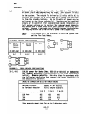
1
IHEX:
PAGE
General Information .......................................................
I.
Introduction
.........................................................
A.
System Characteristics
..........................................
Zone Inputs .....................................................
::
System Options ..................................................
.
Control Options ............................................
Communicator Options .......................................
II.
Functional
Description ...............................................
A.
Functional
Description,
kb. 4160-12 C-COM.......................
Switches ...................................................
1.
LED Indicators .............................................
2.
Functional
Description,
No. 4165 Siren Driver ...................
::
Functional
Description,
No. 5321 Security
Console ...............
Keypad, LEDs and Message Displays ..........................
::
Audible Signals ............................................
0.
Functional
Description,
No. 5314 Remote Keypad ..................
Keypad and LEDs ............................................
::
Audible Signals ............................................
Functional
Description,
No. 9787/9789 Remote Key Arming Station.
E.
III. Conmunicator Operation ...............................................
A.
Line Seizure ....................................................
Anti-Jam ........................................................
Dial Tone Detection .............................................
E:
PROMCalling
Options ............................................
0.
Acknowledge Uait PRDM Options ...................................
E.
Transmission
Format PROMOptions ................................
F.
6.
Message Verification
PROMOptions ...............................
H.
Ademco Low Speed Reporting Format ...............................
Ademco High Speed Reporting Format ..............................
..*..k .............
::
Sescoa/Radionics
Reporting Formats ...........
............................................
IV. Installer
PROH Programing
A.
Control PROM....................................................
8.
..............................................
Comnuni cation PROM
..*.....G ........
v.
Installation
and Wring ..............................
.
Installation
and Wiring,
No. 4160-12 C-COPI...: ..................
Terminals ..................................................
A.
Additional
Connection Posts ................................
B.
.
Installation
and Wiring,
No. 5321 Security
Console ..............
Installation
and Wiring,
IYD. 5314 Remote Keypads ................
VI. System Checkout ......................................................
VII. Operation ............................................................
.../ ..
VIII.Turning
The System Over to User ................................
...............................................
IX. General Specifications
..........................
x.
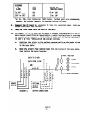
Diagram 4: No. 4160.12 Control/Comnunicator
XI. Diagram 5: No. 4165 Siren Driver .....................................
XII. Diagram 6: No. 5321 Security
Console .................................
XIII.Diagram
7: No. 5314 Remote Digital
Keypad ............................
.....
XIV. Diagram 8: No. 9787/9 Keyswitch Arming Statton.................;
xv.
Diagram 9: SIlmnary of Connections ....................................
678
628
f
3
3
4
ii
9
9
10
10
10
10
13
13
13
14
15
:x
16
16
16
17
17
17
17
:x
23
24
i8
36
::
42
43
45
48
5:
zi
ii
'56
57
GECERAL INFORMATION:
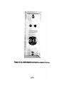
The No. 4160-12 Control/Communicator
is a microcomputer
based product which
conveniently ca&ines the control
panel and digital
carmunicator
into one package.
This commercial-residential
system provides
every important
feature required
for a UL certified
household fire/burglary
alarm installation.
an optional
Eb. 4165
A typical
system installation
includes a No. 4160-12 C-C&
Plug-In Siren Driver,
one or two No. 5321 Security
Consoles,
optionally
(up
to four)
No. 5314 Remote Keypads, and,optionally
(up to four) No. 9787/9789
Remote Key Arming Stations.
The No. 4150-12
C-COn monitors,
signals for interior
cation to a central
all inputs
and generates
appropriate
output
and exterior
audible warning as well as for remote comnunialarm monitoring
service.
The k. 4165 Siren Mver is an optional plug-in module that provides the capability
to drive an 8 ohm siren speaker with up to 25 watts of sound power with separate
sound outputs for fire and burglary/emergency.
In addition,
two separate format
pair combinations
are programmable for this driver.
The @b. 5321 Security Console(s) provide full system and individual
zone status
indication
as well as system control.
With the No. 5321, the system may be
completely
armed or just
perimeter
armed or disarmed.
The entry delay may
be turned off,
tones may be shunted, and a user security
code may be changed.
Three types of emergency alarms may be triggered
(fire,
silent
or audible police
A built-in
speaker provides audible
alarm,
and optional
audible
emergency).
alarm, trouble, and annunciator functions.
The keypad is illuninated
for nighttime
convenience.
The (opttonal)
RD. 5314 Remote Keypad(s) permit most of the keypad functions
of the No. 5321 to be performed except for the panic alarm triggers,,
as well
as providing
limited
display and audible annunciation
for modes, trouble,
alarms,
and shunts.
The (optional)
cb. 9797/9799 Remote Key Arming StatIons permit remote complete
(MAY) aning
and disarming of the system as well as providing
arming/disarming
status
indication.
The system may also be force.armed
from these locations
if one or more zones are faulted.
I.
fNlROM,CTION
A.
system Quracteristics
1.
Six independent
2.
Up to five burglary
zones, and one fire
3.
Console dfgital
numeric display of the
alann memory, and trouble conditions.
4.
Two Keypad arm/disarm codes - master code PROMselectable
code user changeable fran keypad (each uniquely reported
station
with open/close reports).
5.
Indivldual
zones which nay be configured
zones (including
zone.
one day trouble
Zone bypass from the keypad.
628-2
679
in a variety
of ways.
zone),
zone identification
two panic
for
alarms,
and secotiary
to central
6.
Chime mode, duress
7. I PROM variable
sounder timeout,
B.
forced
arming -.additional
keypad functions.
entry/exit
and alarm sounder activation
and ,delayed AC supervision
reporting.
delay,
alarm
8.
Alarm Relay
alarms.
9.
Arming status
detectors.
10.
Zone LEDs at the C-CCM to indicate
11.
AC Power LEDs at the C-COM and Security
Console to
AC power is available
and the battery
is being charged.
12.
Fire
13.
Multi-format
commun+cator (Ademco Low Speed, Ademco High Speed, Sescoa,
Radionics Superfast).
14.
Touchtone or pulse dial
call
15.
Touchtone or pulse.tone
data transmission.
16.
[)ual phone nunber calling
17.
Double transmission
sun verification.
and optional
output
Test Switch
18.
All
19.
Low battery
reporting
plug-in
with
siren
programmable
driver
polarity,for
the status
to check the fire
outputs
for
control
audible
of motion
of each zone.
indicate
that
system functions.
placement.
with
separate
verification
or
independent
single
ID.
subscriber
transmission
with check
.
by zone for alarms,
and AC power fail
troubles,
restores,
shunts.
reporting.
Zone Inputs
1.
Zones l-3:
Burglary
Zone 1 and 2:
Zone 3:
C.
code,
Perimeter
Interior
selectable
2.
Zone 4:
Fire,
Day Trouble
selectable
3.
Zone 5:
Police
4.
Zone 6:
Burglary
Panic (Audible
or Audible
or Entry/Exit
- PROMselectable
with or without
Entry/Exit
delay
- PROM
Burglary,
- PROM
or Silent)
or
Standard
Burglary
- PROMselectable
Emergency Panic - PROMselectable
System t&Wont
The system can be configured
user to custauize
the system
actually
making the choices
(See Section II, Installation),
in a number of ways.
This allows the
Before
for his own particular
needs.
which affect
how the system operates
it is important
to understand
the
628-3
680
The discussion
that follows broadly divides those
options.
into two categories:
control
options and comnunicator options.
options
conmacwmns:
1.
Entry IMy,
Exit Way
The entry delay is the time between entering
the premises
the system must be disarmed
to avoid activating
an alarm.
delay is the time between arming the system and when the
The entry
must be exited
to avoid activating
an alarm.
delays may be independently
PROM selected
to be between
seconds in 15 second increments.
2.
Exterior
SouJlder/Priwry
a1cator
and when
The exit
premises
and exit
0 and 135
IWay
The system may be set up to delay the activation
of the exterior
bell and/or siren (optional
plug-in 4165 siren driver module required).
In addition,
triggering
of the connnunicator may be additionally
delayed.
This feature may be used to reduce false alarms due to operator errors.
The delay may be set in PROM between 0 and 135 seconds in 15 second
increments,
but applies only to those zones that have the delay feature
enabled (See No. 15).
3.
fkll/Siren
Timeout
Bell/Siren
audible
indication
may be PROM selected to last
0 and 36 minutes in 4 minute increments,
after which it "times
4.
l
between
out".
At hwmr Last Timer
To eliminate
nuisance power failure
central
station
and local audible
reports,
the system may be PROM programed to ignore short duration
This delay in reporting
an AC loss condition
may be set
outages.
between 0 and 36 minutes
in 4 minute
increments
(As an example,
if a timeout
period
of 16 minutes
was selected,
power outages of
extinguish
less than 16 minutes
will be ignored - the POUERLED will
inmediately,
however).
5.
mry/Exlt
zane Selection
The system allows a choice of zones that may be set up with entry/exit
Zones 1, 2, and 3, individually
or in any combination,
may
delay.
be set up in PROH as entry/exit
zones (For example, if the interior
zone [zone 33 wtre set up with space protection,
choosing an entry/exit
delay on this
zone would allow space protection
devices to include
the entry door in their
area of protection
which is to say, they
could be held off during the normal entry/exit
period).
6.
Fast Response Zone Wection
Fast (15 msec) response
is used for certain
devices (such as glass
break detectors
and some photoelectrics)
that cannot be used with
Fast response cm be PRM designated
a normal (250 mxc) response zone.
for zones 2, 3 and 4, individually
or in any combination.
628-4
681
7.
Eon0 4 Tup+ Selection
As shipped, zone 4 Is configured
as a standard burglary zone. )t>wever,
it can also be configured
in PROMas either a fully
supervised Fire
Zone or a 24 hour day burglary
zone (during disarmed period, a trouble
indication
is communicated and audibly sounded if the loop is opened
or shorted;
a burglary
alarm is triggered
if the loop is opened or
shorted during armed period).
8.
Zane 5 and 6 Options
As shipped,
zone 5 is configured
as a silent
panic zone, zone 6 as
Optionally,
zone 5 and/or 6 may be configured
in
a burglary
zone.
PROM as audible
panic zones.
In addition,
if zone 5 is set up as
a Silent
Panic Zone, console
display
of both the panic condition
as well as the activity
of the cormlunicator may be inhibited.
(For
example,
if zone 5 is set up as a silent
medical
emergency zone,
the user would want an indication
that the alarm has been triggered,
if the zone 5 is intended for hold-up use, the display would
however,
not be desirable).
9.
~scellamems
PRol Selatablc
Alternate
Control
Options
Siren somds:
As shipped,
the system will
give the following
sounds:
Steady
rapid
two-tone
(Electronic
bell)
for Burglary/Panic;
interrupted
rapid
two-tone
for fire.
Optionally,
steady slow two-tone for
Burglary/Panic
may be PROMselected.
b)
Alarm Sounder .Dlng'
Conflrution
of klimg:
When PROM selected,
this
option
will cause a l/2 second "Ding'
of the exterior
bell and/or siren at the end of the arming sequence.
If the communicator
has been set up to send opening and closing
reports,
the "Ding" will occur when the camnunicator has received
If opening/closing
reports are
a kissoff
on a closing
report.
not used, the "Ding"
will
occur when the exit delay period has
expired.
d
Arming status
RPluity:
The system has an output
at TBI-1 that may be used to indicate
the arm/disarm status of the system to other devices (for exmple,
As shipped, the system will give the following
space protection).
output:
+12 volts Aen armed
0 volts when disarmed
Optionally,
0 volts
the polarity
can be PROMbe reversed
suitable
for
AC powered
when disarmed
628-5
682
to give:
Ademco 12 volt
and
+12 volts
10.
when armed
space protection
devices.
Duress Digit
The duress digit
is a change to the last digit
of the security
code.
Its purpose is to dllow someone to initiate
a silent
panic condition
but still
give the impression
that the control'is
working nonally.
For example,
if the security
code is 1234 and the duress digit
is
5, entering
1234 will
cause the system to disarm, but entering
1235
(assuming
one is in a hostage
situation)
will
cause the system to
disarm,
but will also trigger
the communicator to send a silent
panic
message.
MJTE:
Il.
If the user of the system inadvertently
programs a secondary
security
code that is the same as the master code, but has the
same last
digit
as the PR@4programed duress digit,
the duress
silent
panic capability
is suppressed to avoid the transmission
of false alarms to the central
alarm monitoring
service.
Security
Cade
This 4 digit
code restricts
the use of the system to only those who
Any digits,
including
repetitions,
may be chosen.
know the code.
One is PROM programmed at installation
There are two such codes.
and the second is user changeable
from a keypad at any time, using
the master code to enable the change.
12.
Forced Arming Enable
Forced arming allows
a user to arm the system even though certain
zones are in a faulted
condition.
Such faulted zones will be shunted
.by depressing
BYPASS to override
the fail
safe arming during'the
aming
period.
Forced arming must be PROM enabled for each zone in which
it is desired (with critical
zones, such as safes for instance,
arming
of the syste+&hould
be prevented when a faulted condition
exists).
13.
Bypass Enable
Zones in the system may be individually
bypassed from the Security
Console or Remote Keypad during
the disarmed
period.
This option
allows
the user to bypass zones that should be ignored, whether or
not they are faulted
at arming time (In this manner, "Swingers" may
be ignored
or a loading
dock door that must be later opened can be
left
unsecured).
To allow individual
zone bypass,
each such zone
must be PROMenabled for 'this option.
14.
20~ Restore En&de
As shipped,
the system has all zones set up as non-restore
zones.
Non-restore
means that once a zone has gone into alarm during the
subsequent
faults
of that
zone will
not trigger
a
arming period,
new alarm.
The zone is effectively
"locked-out",
preventing multiple
false alarms in the event of a "Swinger".
Zones that
have been PROM selected
as restore'zones
will
bell/siren
to sound more than once if the zone returns
and faults
again after the bell/siren
has timed out.
628-6
683
allow the
to nonnal
15.
Alam Sotmder Delay.Enable
The "Exterior
Sounder/Primary
Communicator
Delay" was explained
as
option
82, above.
PROMoption
15 is simply the choice of burglary
zones for which exterior
sounder delay is desired.
It should be
noted that the delay does not apply to zone 4 if it is set up as
a fire zone nor to zones 5 or 6 (if set up as panic).
1.
PrrMicator
Enables
The system may be PROM programmed,to
the following
messages:
a)
transmit
any combination
of
Open/Close Reports
A closing
report,
if enabled,
will be sent whenever the system
is put in the AWAY mode.
The STAY mode will
not generate
a
closing
report.
W zoneshuntRepufts
If PROM enabled,
the
the central
station.
the following
times.
::
3.
d
system will
These shunt
report
reports
all
shunted
will
take
zones to
place at
Whenever a 24 hour zone (fire,
panic, etc.)
is shunted.
Burglary zones will report shunting at the time of arming.
When the zone shunt is removed,
a shunt restore
message
will
be sent for 24 hour zones (burglary
zones will
not
send shunt restore
reports
as an open report automatically
signifies
shunt restore for these zones).
Zone 4 Trolrble Reports
The system will
transmit
a trouble
report,
if PROM enabled,
whenever a trouble
condition
is sensed in zone 4.
When the
trouble
condition
has restored
for 16 seconds, a restore message
will be sent (if PROMenabled).
4
Cancel Code
If PROM enabled,
the cancel
code may be used for systems not
utilizing
opening/closing
reports.
The cancel
code will
be
sent if a burglary
alarm is turned
off (cancelled)
before the
bell/siren
times out.
The cancel code does not apply
for fire
or panic reports,
however.
2.
16Secomd
Secondary Commkator
Delay
An additional
16 second delay may be added to the communicator trigger
to reduce the possibility
of false alarms.
This timing begins after
any delay already provided by the Exterior
Sounder/Primary
Conuunicator
The trigger
delay option might be
Delay option
(described
above).
chosen,
for example, on zones not utilizing
the exterior
sounder
In addition
to zones l-6,
trigger
delays are available
for
delay.
628-7
684
both trouble
3.
and closing
reports.
Report to Secondary Phone bmber Oily
The system allows
for the various conxnunicator reports to be divided
between two central:stations
(or two receivers).
This option
is
chosen in some situations,
where, for example,
all alarms may be
routed
to a primary
alarm receiver
while non-critical
items, such
as troubles
or open and closing
reports,
might be routed to a secondary
receiver.
4.
Ml scel laneow
a)
All
~unlcator
kssages
qrtions
On (he Cilll
As shipped,
the system is set up with a feature that gives alarm
messages priority
over trouble
messages and other non-alarm
messages, when sending in a format other than Ademco High Speed.
if an alarm message for the primary receiver
occurs
For example,
while the communicator
is reporting
shunt conditions
to the
secondary receiver,
the coaxnunicator will abort the shunt reports.
It will
then call
the primary
After the alarm has been reported,
reporting
the shunts.
Optionally,
the active
nunber.
W
the system may be made to finish
all messages to
phone number before
switching
to the other phone
Duress kssage
to Second Phone Mmber
When PROM selected,
secondary receiver.
d
receiver
to report
an alarm.
the camnunicator
will
resume
AC Fafl/Test/lm
this
Battery
option
routes
duress
messages to the
to Second Phone ?hmber
When PROM selected,
this
option
routes AC Failure and Restore,
Low Battery,
and Test reports to the secondary receiver.
4
Lou Battery
As shipped,
. will report
l&port
Fomt
Selat
when using Ademco High Speed Format,
Low Battery messages as follows:
ACCT 5555 5555 8
the
system
Low Battery
A PROMoption is available
that enables battery
failure
reporting
in a different
manner (See Section on Hi.gh Speed Format).
This
format also allows battery restore reports to be, transmitted.
d
Dual Report
When PROM selected,
this option causes alJ coaxnunicator messages
to be sent to both a primary receiver
and a secondary receiver.
628-8
685
f)
ALT by 2's
(Alternate
by Pairs)
when PROM selected,
will
cause the communicator
This option,
to alternate
between the primary
receiver
and the secondary
receiver
while. it is attempting
to get through.
It will
first
make two attempts
to the primary
receiver,
then two attempts
to the secondary
receiver
, and so on until
it either receives
a kissoff
signal from one receiver
or exhausts the maximum number
of attempts.
5.
Camnicator
Restore Report Enable
If a zone is set up as a restore
zone (see control
option f14) and
.it is desired to communicate restore,
the reporting
can be PR@lenabled
for any such zone or zones.
6.
&municator
Channel Asstg-t
On the system , each alarm zone, as well as the duress report,may
be assigned
a communicator
channel.
How the zones are assigned to
channels affects
the types of reports that will be sent. As an example,
each zone could be given a different
communicator
code for unique
zone reporting.
& the zones could be grouped by function
with duress
and silent
panic zones as Channel (or Code) 1, the fire zone as Channel
(or Code) 2, and the burglary
zones as Channel (or Code) 3 (this
would allow the system to be compatible
with an existing
central
station
alarm code scheme).
7.
Frunicator
Fomat
Individually
selectable
Ademco LOW Speed and/or
II.
for primary and Secondary telephone
Ademco High Speed, Sescoa, Radionics
numbers Superfast.
FURCTIDRU OESCRIPTIDR
A.
FUETIOML
1.
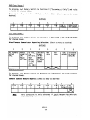
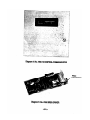
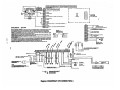
DESCRIPTION, ND. 4160-12 C-C@! (See Diagram 4)
suitcbes:
Rightward
movement of this momentary
FIRE TEST/RESET Sri tch:
action,
center
off switch
shorts
the fire
loop to initiate
an
al arm.
In addition,
the charging
current
to the battery
is
interrupted
while this
switch
is held,
giving
an indication
of battery condition.
The test is reported to the central station
using the Test code.
The fire
test
is reset
by sliding
the
switch to the RESET po.sition.
Leftward
movement of this
switch
resets
the fire circuit.
In
addition,
the power to the smoke detectors is interrupted,
resetting
any detectors
that were activated.
Clearing of the fire alarm
memory indication
on the console and on the C-CCM requires
entry
of the security
code and OFF at a console or keypad.
In addition,
the fire
circuit
may be bypassed by holding the
A fire
trouble
indication
switch to the left
f6r 5 seconds.
will
be provided when the fire circuit
is bypassed.
628-9
686
2.
LED Indicators:
ZONE LEDS FOR ZONES 1, i,
the status
of their
3, 4, 6 (RED):
respective
These
LEDs indicate
zones:
ON STEADY - Existing
Zone Fault
SLOWLYFLASHING - Shunted
RAPIDLY FLASHING - Memory of Alarm
ZOE 4 TROUBLELED (RED):
of zone 4 whether
or as a day trouble
This LED indicates
the trouble
status
It is operating
as a supervised
fire
zone
burglary
zone:
Trouble
ON STEADY - Existing
RAPIDLY FLASHING - Memory of Trouble
This LED indicates
This LED will
system.
PDMERLED (GREEN):
to operate
the
AC power is lost.
6.
the presence of AC power
turn off Mediately
when
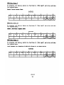
FUllCTIOWiL lE5CRIPTION, tlo. 4165 SXREN-DRIVER(See Magra
5)
Controls:
permits
the
PITCH ADJUSTUENT: The small blue potentiometer
adjustment
of the pitch
of sound produced by the siren driver.
Clockwise adjustment (as viewed from the right side of the cabinet)
increases
the pitch
and counterclockwise
adjustment descreases
the pitch.
c.
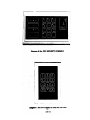
FUICTIONN OESCRIPlION, I@. 5321 SLCURITY COKOLE (Se
1.
Magrr
6)
Keypad, LEDs and Hessage Msplays:
ROTE:
The interval
between consecutive
key depressions
must
greater
than 2 seconds for acceptance
of the
entry.
not be
Keys O-9:
These are
duress digit.
used to enter'the
security
code and the
subsequent
to entry
OFF Key and LED (6ieen) : When depressed
.of the security
code, silences
alarms, memory and trouble audibles
The OFF LED is lit
when the system's
and disarms the system.
burglary
protection'is
turned off.
When depressed
subsequent
to entry
AYAY Key and LED (Red):
burglary
system if there
of the security
code, arms the entire
The AWAY LED is lit
when the system is
are no faulted
zones.
anned in this mode.
When depressed
subsequent
to entry
code, arms all of the burglary
zones except
Protection)
if there are no faulted
zones (other
The STAY LED is lit
when the system is armed
STAY Key and LED (Red) :
of the security
Zone 3 (Interior
than Zone 3).
in thls mode.
628-10
687
POUER LED (6reen):
This LED indicates
to operate
the system.
This LED will
AC power is lost.
the presence of AC power
turn off imnediately
when
BYPASS KEY and LED. (Tellou):
When depressed
of the security
code and' followed by one or
(1 to 6) while
in the disarmed
state,
will
the zone(s)
designated
[assuming
that the
system pennits the shunting of the particular
subsequent to entry
more zone nunber(s)
individually
shunt
programming of the
zone(s)].
When depressed
subsequent
to entry of the security
code and
either
the AWAY or STAY keys, the burglary
system will arm with
any faulted
zones shunted [assuming
that the programming
of
the system permits the forced automatic shunting of the particular
zone(s)].
The BYPASS LED is lit
when one or more zones is shunted either
by force
arming or by individual
shunt selection.
All shunts
are automatically
removed when the system is turned off.
INSTANT Key and LED (Yellow):
When depressed
subsequent
to
entry
of the security
code and either
the AWAY or STAY keys,
the burglary
system will
arm with the entry delay disabled on
any zones designated
as entry/exit
zones, making them instant
alarm zones for subsequent
entry.
The INSTANT LED is lit when
the system is in this mode.
The entry delay for these zones
is restored
subsequent to the system being turned off.
CODE Key and LED (Yet low) : When depressed subsequent to entry
of the security
code, will
permit the entry of a secondary user
changeable 4 digit
security
code.
The code permits the performance
of all 'of the functions
permitted
by the PRDMprogramed master
code except ehange of itself
to a new code.
In addition,
the
secondary code is blocked from performance of any of its functions
.when the system is armed with the master code;as an added security
feature.
Repeating
digits
are permitted
in code entries
and
if the secondary
code entered
happens to be the same code as
the master code except for the secondary code last digit matching
the duress digit,
the duress
silent
panic capability
will be
suppressed
until
the secondary
code is c'hanged, so as to avoid
needless false alarms being reported to the central alarm monitoring
service.
The CODE LED is lit
whenever a secondary code is in
effect.
Uhen depressed subsequent to entry
CHIHE Key and ‘LED (Yetlaw):
of the security
code during
the disarmed
state,
will
enable
a mode in which any fault
in Zones 1 or 2 nil 1 cause a brief
loud tone to be heard at each security
console and remote keypad.
The mode can be disabled
by subsequent reentry of the code and
redepression
of the CHINE key.
The CHIME LED is lit whenever
The CHIME mode is never in effect
the CHIME mode is in effect.
during tNe armed state.
READY Key and LED (6rem) : When depressed at any time, permits
the Zone Identification
Display to identify
any presently
faulted
Subsequent entry of the security code followed by depression
zones.
The READY LED is
of the OFF Key turns
off the zone display.
628-11
688
1 it whenever all zones are intact
(ready
for
the disarmed state.
It 1s off at other times.
arming)
during
ENTERKey: When depressed subsequent t0 security code and function
or mode entry,
eliminates
the 2 second keying, delay that exists
prior
to acting
on the function
or mode request
(use of this
key is optional).
FIRE and FIRE Keys and LED (Red): Simultaneous
depression
of
both keys causes manual activation
of the fire alarm (if fire
The FIRE LED is lit
when a fire
is programmed for Zone 4).
alarm has been caused by this means or by a short in the fire
zone and remains as a memory of alarm after timeout.
POLICE and POLICE Keys and LED (Red):
Simultaneous depression
of both keys causes manual activation
of a Zone 5 alarm (audible
or silent
as a function
of zone programming).
The POLICE LED
is lit
when a Zone 5 Police alarm has been caused by this means
or by a fault
in Zone 5 AND,Zone 5 has been programmed with
the console
display
enabled.
It remains lit
as a memory of
alarm after timeout.
EHERG and EMERG Keys and LED (Red):
Simultaneous
depression
of both keys causes manual activation
of a Zone 6 audible alarm
(if
Zone 6 was programmed as a 24 hour alarm zone).
The EMERG
LED is lit
when a Zone 6 Emergency Alarm has been caused by
this means or by a fault in Zone 6 AND Zone 6 has been programned
It remains lit
as a memory of
for 24 hour emergency alarms.
alarm after timeout.
AUX and AUX Keys and LED (Red):
,+lot Used - Future
Application.
ZDIE. IE~IFICATION
DISPLAY (Red): This one digit
display provides
the zone identification
for each zone programed as a burglary
zone during
the disarmed
and armed states,
for both current
faults
as well as for memory of alarm.
This message is displayed subsequent
IUNUNJtY Message Display (Red):
to intrusion
in one of the burglary
zones when the system is
armed and remains, along with the Zone I.D. Display,
as a memory
of alann after the alarm condition
is removed.
CHECKMessage Display (Red): This message is displayed subsequent
to a trouble
condition
being detected in Zone 4, when this zone
is programmed as either
a fire
zone or a day trouble burglary
Lone, and remains as a memory of the trouble after the trouble
condition
is removed.
This message lights
steadily
while
PHONE Uesuge Display (Red):
any phone transmission
(except-a
silent
alarm where the system
is programned for console inhibit)
of an alarm,trotile,open/close,
When the central alarm monitoring
cancel, or restore is in process.
service
receiver
acknowledges the transmission
with a kiss off,
the message will
flash for 30 seconds.
628-12
689
2.
Audible
Fire
Signals
Alarm:
Interrupted,
accompanied
Burqlary/Audible
rapidly
by lighting
Police/Emergency
alternating
two-tone
of FIRE LEO.
sound
Alarm:
Either
continuous
rapidly
alternating
two-tone
sound or
continuous
slowly
alternating
two-tone
sound (dependent
upon system programing)
accompanied by lighting
of BURGLRY
message, POLICE LED, or EMERGENCYLED.
System Turned DFF or Failure to Arm:
Single brief tone
System Armed AWAY:
Two brief tones
Three brief tones
.System Armed STAY:
Trouble:
Rapidly
pulsing
tones for a Zone 4 trouble
or
for a loss
of AC power beyond the programmed
time period.
Entry Warning: Slowly pulsing
tones activated
during the entry
delay period.
Single
tone each time Zone 1 or 2 is
Chime Annunciation:
faulted when in this mode.
Memory of Alarm:
Rapidly
pulsing
tones activated
during
the entry
delay period
subsequent
to
an al arm or after
disarming
subsequent
to an alarm.
Key Depression Feedback: Brief
buzz tone
for each key not in
the dual key panic section of tk keypad.
0.
,r?
FUNCTIONALDESCRIPTION, ND. 5314 REMOTEKEYPAD(See Diagram 7)
1.
Keypad and LEDs:
Keys O-9: These
duress digit.
are
used to enter
the
security
code
and the
subsequent
to entry of the security
OFF Key: When depressed
code, silencesalarms, memory, and trouble audibles and disarms
the system.
subsequent
to entry
WAY Key and LED (Red): When depressed
system if there
of the security
code , arms the entire burglary
The AWAY LED is lit
when the system is
are no faulted
zones.
armed in this mode.
STAY Key and LED (Red):
When depressed
subsequent
to entry
of the security
code, arms all
of the burglary
zones except
for Zone 3 (Interior
Protection)
if there are no faulted
zones
The STAY LED is lit
when the system is
(other
than Zone 3).
armed in this mode.
This
LED lights
steadily
if a zone
CHK.BYP LED (Yellow):
has been shunted by either
force arming or individual zone shunting.
It flashes
if a trouble
condition
in Zone 4 has been detected.
The trouble
indication
overrides
the shunt indication
if both
628-13
690
,’
are present
tjmultaneously.
When depressed subsequent to entry of the
BYPASS Key:
code and followed
by one or more zone number(s) (1 to
in the disarmed state, will
individually
shunt the zone(s)
[provided
that the prograrnning of the system permits the
of the particular
zone(s)].
security
6) while
designated
shunting
When depressed
subsequent
to entry of the security
code and
either
the AWAY or STAY keys, the burglary
system will arm with
any faulted
zones shunted
[provided
that'the
programming
of
the system permits
the forced automatic
shunting of the faulted
zone(s)].
When depressed subsequent to entry of the security
II(sTANT Key:
code and either
the AWAYor STAY keys, the burglary system will
arm with the entry
delay disabled
on any zones designated
as
entry/exit
zones making them instant
alarm zones for.subsequent
The entry delay is restored
subsequent
to the system
entry.
being turned off.
CDIIE Kcy: When depressed
subsequent
to entry of the security
code, will
permit
the entry
of a secondary
user changeable 4
The code permits
the performance of all
digit
security
code.
of the functions
permitted
by the PROM programned master code
except change of itself
to a new code.
In addition,
the secondary
code is blocked
from performance
of a,ny of its functions
when
:;;t;;;tem
is armed with the master code, as an added security
Repeating
digits
are permitted
in code entrles
and
if the iecondary
code entered
happens to be the same code as
the master code except for the secondary code last digit matching
the duress digit,
the duress silent
panic capability
will
be
suppressed
until
the secondary
code is changed so as to 'avoid
needless false al arms being reported to the central alarm monitoring
service.
When depressed
subsequent to entry of the security
CHINE Key:
code during
the disarmed
state , will
enable a mode where any
fault
in Zones 1 or 2 will
cause a brief
loud tone to be heard
at each security
console
and remote keypad.
The mode can be
disabled
by subsequent
reentry
of the code and depression
of
the OFF key.
BEADYLED (Dmea):
(ready
for
other times.
arming)
This LED is lit whenever all zones are intact
during
the disarmed
state.
It is off at
ENTERKey: When depressed subsequent to security code and function
or mode entry,
eliminates
the 2 second keying delay that exists
prior
to acttng
on the function
or mode request
(use of the
key is optional).
2.
M$blc
Signals:
System.Turned WE or .Failure
sy.st~em Armed MAY
System Armed Sd
to Arm:
628-14
691
Single brief buzz
Two brief buzzes
Three brief buzzes
Trouble:
Entry
Rapidly
pulsing
buzz for a Zone 4 trouble
or
for a loss of AC power beyond the programmed
time period.
Warnin,g: Slowly pulsing
buzz activated
during
the entry
delay period
subsequent
to an alarm or after
disarming subsequent to an alarm.
Key Depression
E.
FUNCTIOlUL
Diagru
Feedback:
Brief
buzz for
DESCRIPTIOW, RD. 9787/9789
each key depressed.
REMOTE:KEY AAIIICIG STATIOR (See
8)
wDlmrrWcyswlkh'
'
Momentary
clockwise
turning
of the
key causes
AWAY arming
disarming,
trouble
and memory of ilarm
audible
clearing.
Holding
the keyswitch
in the clockwise
turned position
for a period of 5 seconds,
when attempting
to arm AWAY with a
faulted
zone,
causes
forced
arming
with automatic
shunting
of the faulted
zones (if permitted
by zone programing).
Rrd LED:
When lit
steady,
this
LED indicates
that the burglary system is armed.
This
LED flashes
of alarm indication.
Grwn
III.
LED:
CamlwICATm
When lit,
this
zones are intact
This LED ironly
state.
to
provide
a memory
LED indicates
that all
and ready for arming.
lit during the disarmed
OPERATION
The communications
capability
of the system links it with a monitoring
central
When alarm,
trouble,
or status
station
using the telephone switched network.
information
is to be communicated, it is translated
into a message appropriate
to the format selected
via the various
PROM options
described
previously.
The system then seizes the phone line.
A.
Line
kialre
A Double Pole Double Throw relay
disconnects
all extension
phones
on this telephone
line
so that the communicator
cannot be blocked
by outgoing calls or by a phone left off hook.
The system&n
executes
a short 166 second hang-up, to insure a disconnect
in case an outgoing
a communication link.
call
was being made , and attempts to establish
At this time the PHONEmessage on the console will
light
for alarms
If the system is unsuccessful
in
not inhibited
for this
action.
establishing
the 'link,
an anti-jam
procedure is executed if the telco
network used features "called
party disconnect."
628-15
692
B.
krti-Ju
Fhny U.S. telephone networks will automatically
disconnect the calling
party if the called party hangs up for a period of time.
the system
automatically
executes a 30 second anti-jam
(hang up) AFTER the first
call attempt and each successive call to prevent
any incoming
calls
from blocking transmission.
E:
Only if
The canunicator
for a dial tone.
C.
link
PROMselected.
is established
in the following
manner.
The system checks
Dial Tone Detection
In order to reduce response time, the system senses both local (PBX)
and external
(telco)
dial
tones.
If a dial
tone is detected,
the
system dials
using the PRU4 selected Touchtone or rotary dial format.
If a dial tone is not detected within a PROMprogramned waiting period,
the system will
dial
anyway, as it assumes that a good connection
has been made and that the dial tone is not clear.
The PROMselectable
.
.
.
waiting
periods
are:
5 seconds - for quick disconnect Telco or PABX systems
11 seconds - for normal telco systems
30 seconds - for
slow response
telco
The system dials
up to two separate
16 digft
programned to do this in a nunber of ways.
D.
PRaN calling
systems
telephone
numbers..
It
may be
options
.
to
Altetnrk'by
PaIts - Call the second number upon failing
receive
Kissoff
after
two attempts
to the primary nunber, then
alternate
every two calls between the primary and second number
until
Kissoff
is received
from one or until the maximua nunber
of attempts is reached.
.
Our1 Report
fran
first
.
or having
nunber.
- Always
reached
call
the
the second nunber even after
maximum number of attempts
Second hmber
only
Only - Having selected alarm code/channels
to the second nunber (e.g. open/close
reports)
Kissoff
to the
report
Successful
connections
are verified
when the system receives an acknowledgment
If this tone is not received
within
tone fran the central; station
receiver.
a defined
period,
the system will disconnect
from the line and wait 30 seconds
before tryfng
again.
The calling
procedure ~111 be repeated in varying canbinations,
as programned, until
a successful
link is established
or until
the maximum
nunber of attempts is reached.
628-l
693
6
E.
Acknowledge Halt PRM Options
.
.
30 seconds - standard
60 seconds - slow response
central
station
systems
Message transmission
will begin when the acknowledgnent is received.
The system
will
transmit
in the Ademco LOW or HIGH SPEED formats
depending
upon which
acknowledgnent tone has been received
from the central
station.
The latter
is not true for SESCOA or Radionics
Superfast
formats which are specifically
programa& for proper response to their acknowledge and acknowledge-hold
receiver
signals.
F.
Transmission
.
.
.
.
NINE:
Fomat PRO4 Options
Ademco High Speed Chly
Ademco High or Low Speed (depends on C.S. receiver
SESCOA
Radionics "Superfast"
Extended reporting
PROMselectable.
tone received)
from each of the above formats is separately
To ensure proper transmission,
each message is sent up to four times.
As soon
as the central
station
receiver
verifies
the message,
it sends a "Kissoff"
tone to the system.
This causes the PHONE display
on the console to flash
for 30 seconds.
G.
B&sage Verification
PRQl aptions
.
Two successive
identical
messages - Ademco Fb. 673 and 685 receivers
as well as Adcor, Franklin,
Radionics,
SESCOA, Silent Knight,
and Vertex receivers.
.
Single message transmission
with check sum verification
A. 685 (in High Speed Format only) and Radionics
- Ademco
If the system does not receive the "Kissoff"
tone, it will disconnect
and dial
again.
It will make as many attempts
to obtain
kissoff
via the primary
and
secondary phone numbers as is PROMprogrammed.
H.
Muco
law Speed Reportlng
Fom
This message consists
of the last
cation nunber and'a single
digit
alarm/trouble/status
'report.
3 digits
of the subscriber
alarm code PRO?4assigned
identifito that
If more than one alarm is triggered,
the alarms will
report in priority
order (i.e.
low alarm code first)
unless tb subsequent alarms trigger
transmission.
while one or more alarm messages have already ned
before the next is sent.
Each message must receive "kissoff"
Example:
If codes 3 and 6 of Subscriber
system will respond as follows:
628-17
694
-1890 are
to be reported,
the
890 3
890 3'
"Kissoff"
890 6
890 6*
Final "kissoff"
in this
E:
Only the last
3 digits
of the subscriber
identification
be sent in this case.
The full 4 digits
will be used in
with the HIGH SPEED FORMATdescribed later.
optional
Alma/Trouble
.
that
tm,
identical
hang-up)
*Assunes,
Expanded Repotting
example,
(system
messages verification
is used.
number will
conjunction
Capabilitlcs
l&potthg
by Zene
Each zone within the C-COM can be assigned its own alarm code or multiple
zones
can be grouped on a common code, installer.choice.
. tbwever, other types of
reports can be uniquely identified
by using extended reporting.
Extended reporting
operates as follows ,for each of the below cited examples:
Alrm
Rtstotal
Message Sent =
Where:
0
890
RP~RI
R1
Z
RI
t
nuneric
2
=
Zone number
alarm restoral
890 = Sample Subscriber
Ttoublc
Trouble
Account
Nnnber
Ttnmlsmn
890 T
TTT Z
Me5sage Sent Where:
code selected
T
= nuneric
trouble
z
= zone nunber
code selected
ibcsmtal
Message Sent=
R2
iG2Z
Where:
R2 - nuneric
2
trouble
restoral
code selected
= nunber of zone restored
SNalt Report
Message Sent=
890 s
sss 2
628- 18
695
Where:
= nuneric shunt code selected
= nwnber of zone shunted
Message Sent =
Where:
890
R3
R3R3R3 2
R3
= numeric
2
= nwuber of zone for
shunt restoral
User Identification
at (&en/Close
Message Sent =
890 C
ccc u
Where:
C
U
= nuneric closing
= User ID nunber,
Similar
Code.
low Battery
which shunt was removed,
code selected
1 or 2.
Opening except
that
Closing
Code is replaced
by the @ening
Restoral
Message Sent =
Where:
for
code selected
890 BBBB R4
B
= low battery
=
low battery
R4
report code selected
restoral
code selected
Lots of AC lbtoral
Message Sent =
Where:
I.
890 A
AAA R5
A
= AC loss report code selected
=
AC restoral
code selected
R5
ADEMCOHI81 SPEED REMRTIffi
FURMAT
Receipt by the system of a high speed acknowledgment
tone from a No. 685-2
Line Card in a No. 685 Digital
Alarm Receiver will
result
in HIGH SPEED FORMAT
transmissions,
each containing
13 digits
as follows:
4 digit
subscriber
identification
number, 8 digits
defining
the status of each of the alarm reporting
channels, and 1 digit
defining
the status of the ninth auxiliary
channel.
JJOTJ:
If the system is programmed for Ademco format (that is, neither
the
SESCOAnor the Radionics system programming
option
described
under
PROGRAMMINGOPTIONS has been selected),
it will automatically
respond
at HIGH SPEED to a high speed acknowledgnent
tone and at LOW SPEED
to a low speed (or standard) acknowledgment tone.
b special. re-programning of the PROMchip is required
for HIGH SPEED. Only the last
3 digits
of the 4 digit
subscriber
identification
code will be +nt
at LaJ SPEED; therefore,
to ensure the same identification
at HIGH
SPEED as'at LOW SPEED, program the first
digit
as a "0".
628-19
696
As the number of subscribers
calling
into the central monitoring
station increases
beyond 1000 (subscriber
identification
number 999). the No. 685-2 Line Cards
can easily
be modified
to send on1 the high speed acknowledgment tone.
Subsequently connected
systems may +t en be programmed with subscriber
numbers
lOOO-through 9999.
For the
(digits
six alarm reporting
channels
5 through lo), the channel status
Meaning
Code
NEW ALARM CR CONDITION (previously
unreported)
NEW RESTORE (previously
unreported)
NORMAL (no event since previously
reported RESTORE)
PREVIOUSLY REPORTEDALARM (OR CONDITION) STILL IN EFFECT
1
3
ii
For the ninth
T
.4
6"
.7
8
9
NOTE:
codes are as follows:
channel
(digit
13),
the
following
channel
status
codes are used:
OPENING REPORTin the previous 8 channels
SHUNT REPORTin the previous 8 channels
CLOSING REPORTin the previous 8 channels
TROUBLE REPORTin the previous 8 channels
SYSTEM TROUBLEREPORTSin the.previous
8 channels
NORMAL- alarms are reported
in previous 8 channels
NEW LOW BATTERY (will
not re-report
on subsequent
calls
and
will
not send restore)
- old high speed format method for reporting
system low battery
- alarms are reported in the previous 8 channels
TEST REPORT - .alarms are reported in the previous 8 channels
Only NEW events:
ALARM (or OPENING), or RESTORE (or CLOSING) on
any channel or TROUBLEor 24 hour zone SHUNTS or TEST will
trigger
transmission,
at which time all g channels will
report.
Examples (HIGH .SPEED format):
1.
At subscriber
#28gO, channels
1 through
6 (7 and 8 are not used in this
system) are normal and a low battery
(channel
9) initiates
a call.
The
following
message will
be sent:
Subscriber
Identification
Message:
2890
Channel 9:
2.
Channel Flumber
1234
5678
5555'
5555
MU LOW BATTERY
9
8
At subscriber
#58gO, channels 2 and 5 go into.alarm
(and initiate
a call)
and channel 6, which has previously
reported an alarm is still
triggered.
Subscriber
Identification
kssage:
5890
Channel 2:
Channel 5:
Channel 6:
Channel lYlmber
l.234.,5678
g
5155
1655
7
MU ALARM
NW ALARM
PREVIOUSLY REPORTEDALARM
(still
in effect)
628-20
697
3.
Still
at subscriber
2 restores
(initiating
85890, following
the events of example 2 above, channel
the call)
and channels 5 and 6 remain in alarm:
Subscriber
Xdentification'
Message:
5890
Channel 2:
Channels 5,6:
4.
Subscriber
Channel Number
1234
5678
5355
7
6655
MW RESTORE
PREVIOUSLYREPORTEDALARMS
(still
in effect)
#0135 sends an opening:
Subscriber
Identification
Message:
5.
After
0135
Channel 1:
Channels 2-9:
transmission
Channel &mber
1234
5678
of Example 4, subscriber
0135
Channel 1:
Channels 2-9:
6.
E:
Message:
#0135 sends a closing:
Channel kmber
1234
5678
9
4
1444
4444
USER ID - User 81 closed
CLOSING REPORTTRAMMITTED
Subscriber
#0135, User #l force
2 to be shunted (for the sake of
a requisite).
*
Message:
9
2
1222
2222
USER ID - User #l opened
OPENINGREPORTTRANSMITTED
Subscriber
Identification
Message:
9
arms the system, causing
faulted
zone
this
example,
Zone 2 = Channel 2, not
Subscriber
Identification
Channel kmber
1234
5678
0135
0135
5155
1444
4 4 4 4
5 5 5 5
9
4
3
(Closing Report)
(Shunt Report)
Shunt reports
always accompany closing
reports when burglary
zones
If indiv idual zone shunting
had been performed
prior
are shunted.
would be sent later
when the system
to arming,
the shunt reports
If a 24 hour zone (e.g.
fire,
was armed and the clos ing report sent.
panic)
were to be individually
shunted
(if
permitted
by installer
PROMoption),
the shunt report
depicted
below would be transmitted
The example below shows a shunt report for Zone.5.
inxnediately.
Subscriber
Identification
Channel l@mber
1234
5678
9
0135
5555
3
1555
Shunt restorals
are not transmitted
for burglary
zones as these zones are known
to have been restored
when the system is disarmed
and the opening report is
Shunt restorals
are transmitted
for 24 hour zones,
however,
when
transmitted.
the restoral
takes place.
5355
.,. .’ ..
5890
7.
If a trouble
condition
report is transmitted.,
occurs
.
-
Subscriber
:
Identification,‘
5890
Wessage:
Trouble
restoral
is transmitted
8.
Zone 4'for
'-:
Channel
3
subscriber
.:
f5890,
a trouble
&ber
1234
5.6789
5551
5 5.5 5
as soon as it
.’
5
occurs.
5553
5890
NOTE:
in
555.5
5555
5
For trouble
and shunt reports,
the communicator channels correspond
directly
to the zones of the system, regardless
of the zone-to-channel
For example, Zone 4 trouble
will always be reported
mapping chosen.
in the Channel 4 position
of a trouble report.
If a system trouble
exists.
Subscriber
Identification
Rbr loss of AC Reportfag
Message:
condition
occurs
, a separate
trouble
message fonaat
Channel kmber
1234
(Channel
5678
9
1 is used)
0135
1555
5555
6
0135
3555
5555
6
For AC lbcstorrl
Message:
If the "Low Battery
condition
For kq
Message:
will.
Bat-y
Report
be reported
Ikgortlng
in New Format" option
as follows:
(Channel
0135
has been selected,
the
battery
2 is used)
5155
5555
6
5355
5555
6
ForLaulbtte!ryrmtoral
Message:
3.
0135
SESCtM/RADIONlCS REpollTIlff
FOWUTS
The message structure
used for these formats
is similar
to that used for the
However, the full
hexadecimal
code set (O-9, B-F)
Ademco Low Speed format.
It should be noted that the hexadecimal
code set can be used
can be used.
for the Ademco Low Speed format but only on receivers
capable of decoding,
displaying.and
printing
the message data (the No. 660/673 Receivers
can only
accommodate the code set of l-9).
628-22
699
The system employs two PROMintegrated
circuits
for selection
of system options,
one primarily
for control
characteristicf
ihd one totally
for communicator
charMeristics.
These PRCB4sare ordered se#Wately,
Ademco ND. 691 if blank
and till1 be progrwed
by,the installer
or )so. 6glP if the programming
is done
by hdemco to customer order.
In either case the following
feature charts need
to b& canpleted as a record of the system cbnfiguration.
628-23
700
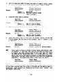
CUSTOMERRAME
CUSTCHERiDDRESS
NOTE:
CUST.
NO.
Program the numbers that you write into the boxes except for double
boxes,where you program the number preprinted
in a box next to the
box you check.
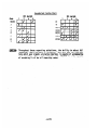
A.
Control
PROM
PRC&IDataI -Group 1
To program,
to Position
set Phone No. Selector
Switch to "Secondary"
2 (Main Phone No.) on ?@I. 690 PROMProgrammer.
and Rotary
1.
Entry Delay
(Se1ect O-49)
0
X 15 sets =
2.
Exit Delay
(Se1ect O-49)
q
X 15 sets =
3.
Exterior Alarm Sounder/
(Select
Primary Camlnicator
Delay
O--)9)
0
X 15 sets =
4.
Alarw Soun&r
Timeout
O--)9)
q
X
5.
AC Power Fail
Delay
Reaction
6.
Select Zones with Entry/Exit
(Select
(Select
0-->9)
Delay:
0
Switch
4 mins =
X * 4 mins =
Check Dne
of
Box
Checked
Znl=rl'
Zns 1, 3 =[rI
7.
=[rj
Zn2
Zn 3 =vl
Zns2,4=Is((
Night
9.
Burglary
=
m
0
Zn3
=f?ll
Check Une
Zns 2, 3 =[-Yji
Zns3,4=lrl
Zone 4 Type Wection:
=TjT7
Zns 1, 2, 3 =I711
Zns 2, 3 =vI
Select Fast Response (15 msec) Zones:
Zn 2 =\r]
8.
Zns1,2
None =,wl
m
Zn 4 3 .4
Zns2,3,4=lTl
Non;=lr1
Check One
Fire
Zones 5 and 6 Type Selection:
=
m
1
Day/Right
Burglary
Check One
Zn 5 = Silent
Panic (Console
Display
On),
Zn 6 = Burglary:
Zn 5 = Silent
Panic (Console
Display
Off),
Zq 6. = Burglary:
Zn 5 = Silent
Panic (Console
Display
On), Zn 6 t Audible
Zn 5 = Silent
Panic (Console
Display
Off),
628-24
701
q
Zn 6 P Audible
0
m n
m
m
m
m
=
2
0
4
Panic:
Panic:
2
6
Zn 5 = Audible
Panic,
Zn 6 = Burglary:
[Ti
fn 5 = Audible
Panic,
Zn 6 = Audible
Panic:
10. Alarm Sounder Options:
m
III
3
:
,:
!
Check Cne
'.
There are two burglary
siren
output
formats
from which to select if the
optional
No. 4165 Siren Driver is to be used.. Output #l is a slowly
alternating HI/LO sound that is similar
to the sound produced by emergency vehicles
in sane locales.
Cutput 82 is a rapidly
alternating
HI/L@ sound that is
more 1 ike an electronic
bell sound.
The confirmation
of arming "ding" is a brief
l/2 second pulse of
alarm sounder to advise the subscriber
that the system has set up
after
they are outside
the premises.
Primarily
for commercial
"Ding" is produced after kissoff (by the central
station
receiver)
reporting
is programmed or after
the exit
delay has ended
reporting
is not selected.
the exterior
successfully
usage, this
if "closing"
if "closing"
The separate
A and B designations
relate
to the selection
of the signal
polarity
of the output on TM-l.
This output presents the system's
"arming
to external
controlled
devices
(e.g.
motion detectors,
contact
status"
identification
annunciator).
"A" selection
yields
a 0 Volt output
for
".Disarmed",
a Voltage
output
for "Armed".
"B" selection
yields a Voltage
output for "Disarmed",
0 Volt output for "Armed."
Burglary Siren Output #l (Slow Alt. HI/LO), & Confirmatii
of Arming "Ding":
Burglary Siren Output 812 (Rapid Alt. HI/LO), & Confirmat
of Arming "Ding":
Burglary
Siren
Q&put
#l,
Confirmation
of Arming "Ding":
Burglary
Siren
Output
#2, Confirmation
of Arming "Ding":
11.
Duress Digit
12.
Mi
(Select
O--)9):
/7
‘._
.’
q
used
PRQI Data Group 2
To program, set Phone No. Selector
Position
2 (Main Phone No.) on lb.
Switch to "Primary"
690 PROMProgrammer.
and Rotary
1.
Cammicator
Al am Code/Channel* Assigned to Zone 1: cl
2.
Cammicator
Al arm Code/Channel* Assigned to Zone 2: n
3.
Communicator Alarm Code/Channel* Assigned to Zane 3: [7
4.
Ccmmunicator Al am Code/Channel* Assigned to Zone 4:
5.
Camnicator
Al arm Code/Channel* Assigned tb tone 5:
Switch
to
q
q
‘_
628-25
702
I
-@!
.
6.
Comunicator
Al am Code/Channel* Assigned to Zone 6’: D
7.
Cmmunicator
Alarm Code/Channel* Assigned to Duress Alara:
8-12.
used.
Iat
Select
I-->8
for communicator
allowed. Select 0 if connunicator
'NOTE:
PRC+l Data Grout
reports
report
duplicate
not desired
Security
assignments
for a zone.
3
lo program,
set Phone No. Selector
Switch to "Primary"
Position
3 (Subs ID #) on No. 690 PRC?l Progralrmer.
Master
cl
Code (Select
The following
capabilities
as desired for each zone:
from O--9 digit
Cl'clncl
are
set,
individually
repeating
selected
and Rotary
digits
by zone,
Switch to
permitted):
check
as many
PROMData Group 4
To program, set Rotary
and raise switches for
~unfcator
(check
Switch to Position
checked boxes.
6 ("Inverted")
on NJ. 690 PRM Programner
Report Se1ection :
as many as desired)
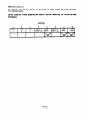
SWITCHES
1
' DPEk
--me
CIWF
2
SHUNTED
7nNF<
--v-w
--..ti-
I
NOTE
3:
3
LONE 4
,
TRnllRI F
.
..“....WW
4
AC.kAIL
---a-In
,
-.s
5
CAKEL
RATT
w...
.
I
I
.
6
NOT
USED
7
T
":D
8
NOT '
USED
t?rmF
.e.H.s-
I
1.
Shunted Burglary
Zone Report is transmitted
at Armed AWAYtime.
Shunted 24 Hour Zone Report is transmitted
imnecliately.
2.
Cancel Code is transmitted
while the alarm sounder is
and panic alarms)
if a burglary
sounding
(not
alarm is
applicable
turned
to
off
fire
PRDM Data Group 5
To program, set Rotary
for checked boxes.
Switch
to Position
Secondary 16 second Conmunicatiw
Report
7 ("16
Delay:
SWITChES
628-26
703
Set Delay")
(check reports
and raise
switches
for which desired)
PHCM Data Group 6
To program,
set Rotary Switch
for checked boxes.
switches
Communicator
desired)
Report
to Position
to Second Telephone
8 ("Secondary
Number ONLY:
# Only")
(Check reports
and raise
for
which
S!JITCHES
l
2
ZCNE
2
1
ZONE
1
4
ZCNE
4
3
5
2(!14E
5
ZC:E
5
7
ZCNE 4
TROUBLE
8
OPEN/CLOSE
AhP SHUNTS
.
PR@l Data Group 7
set Rotary
To program,
for checked boxes.
Miscellaneous
Switch
Coamunicator
to Position
Reporting
9 ("Cpen/Close")
Selection:
and raise
switches
(Check as many as desired)
SWITCHES
1
4
3
2
ALL REPORTS DURESS
ON OM
ALARM TO
2NC
CALL
TELCO
NO. ONLY
AC FAIL,
LOW
BATTERY,
TEST
REPORT
TO 2ND
5
LOWBATT
REPORT
IN NEW
ADEMCO
HI SPEED
FORMAT
6
NOT
USED
NOT
USED
7
8
DUAL ALTERNATE
REPORT BY PAIRS
DIALING
PRCM Data 61 ,up 8
To program,
set Rotary
for checked boxes.
Central
Stat$on
Restore
1
Zl?E
!
WI-E:
2
switch
Reports:
3
Z (IKE
3
to
Position
10 ("Restore")
and raise
switches
(check as many as desired)
4
ZQNE
4
5
ZOfC
5
6 -7
8
NOT
z CIriE ZCM 4
6
TRCIJBLE USED
l
This selection
is only relevant
if.Local
Restore for Multiple
Alarm Sounding has been selected (see PROMData Group 11)
628-27
704
PRO!4Data Group g
set Rotary
To program,
for checked boxes..
Witch
to
Position
11 (“b&t
Used") and raise
switches
12 ("Mot Used") and raise
switches
Permit Forced Arming Shunt
SWITCHES
PRUI Data Group 10
set Rotary
To program,
for checked boxes.
Permit
Individual
Switch
to
Position
Keypad Shunt
SWITCHES
ZOlNE
1
ZO%E
2
ZOiE
3
ZOL
ZiNE
5
4
z6orE
6
7
NOT
USED
8
NOT
USED
PRU4 Data Group 11
4D
set Rotary
To program,
for checked boxes.
Switch
to
Position
Local Restore for Sounding of Wt4ple
13 ("lsrt
Used") and raise
Alarms in an Amed Period
SUITCHES
628-28
705
switches
PROM Data Group 12
To program,
set Rotary
for checked boxes.
Delay Exterior
Previously
Switch
to
Position
14 ("Fbt
Alarm Sounding and Central
Station
Used")
Reporting
and raise
switches
for Period Defined
SWITCHES
ZOL
1
2
ZONE
2
3
ZONE
3
4
ZONE 4
(9NLY IF
5
NOT
USED
6
ZONE 6
(ONLY IF
-.
.
628-29
706
7
EOT
USED
R
NOT
USED
B,
Comunication
PROn
PRCMData Group 1
To program,
set Phone No. Selector
Switch to
Position
1 (Access #) on No. 690 PROMProgranxner
Primary PABX Access s*
(Select
from O--)9,
"Primary"
and Rotary
Up to 4 digits):
Switch to
ClO00
(ex:
9)
PRCMData Group 2
set Phone No. Selector
Switch to "Secondary"
1 (Access #) on MO. 6sl. PRCH Programner.
To program,
to Position
Secondary PABX Access W
(Select
from O--)9,
and Rotary
Switch
Up to 4 digits):~~[~r1
PRC+lData Group 3
To program,
set Phone No. Selector
Switch to "Primary"
Position
2 (Main Phone No.) on No. 690 PRCPIProgramner.
and Rotary
Switch to
12 digits):
[ex:
Out of Area Access digit
(l),
Area Code, Exchange,
Line
Number]
PROMData Group 4
To program,
to Position
set Phone No. Selector
Switch to."Secondary"
2 (Main Phone No.) on No. 690 PROMProgrammer.
Secondary Telco W*
(Select
nclclOclclclnclcl0cl
l WUiE:
Trailing
blanks
number of digits
from 0-->9,
and Rotary
Switch
up to 12 digits):.
are permissible
for entries
less than the maximun
but leading or intermediate
blanks are m allowed.
PROMData Group 5
To program,
set Phone No. Selector
Switch to
Position
3 (Subs ID#) on No. 690 PRWProgramner.
Primary Subscdber
IP
(Select
from 0-->9):
00
"Primary'
0
and Rotary
Switch to
0
PRCMData Group 6
To program,
set Phone No. Selector
Switch to
to Position
3 (Subs IO#) on No. 690 Programmer.
Secondary Subscriber
-NOTE:
IP
(Se\ ect from 0-->9):
"Secondary"
mn
The leading
All 4 digits
must be filled
in.
for Ademco Low Speed, SESCOA, and Radionics.
are transmitted.
628-30
707
and Rotary
Switch
r]n
digit
is
Only the
not
last
transmitted.
3 digits
PROMData Group 7
To program,
set Rotary
Switch to Position
for checked boxes representing
bits set within
Memco Low Speed/SEXOA/Radionics
(Select
from 0-->9,
Reporting
4 ("Not Used") and raise
the hexadecimal code.
Codes for Trouble
and Trouble I&store
B-->F)
Trouble
Trouble
cl
SWITCHES I
I
4
15
3
Cl
I
I 1
2
I
I
Bit
switches
2
1
Weight
8
4
7 =1+2+4,B
(ex:
.,
6
2
1
8
7
I I
I
I
Restore
I I
8
4
=1+2+8,C=4+8,0=1+4+8)
PROMData Group 8
To program,
set Rotary Switch to Position
5 (Yys Options")
and raise
for checked boxes representing
bits set within the hexadecimal code.
Ademco Lou Speed/SESCOA/Radionics Reporting
.from O--)9,
Codes for @ening and.Closing
(Select
BY->F)
Closing
Dpening
cl
SWITCHES (
I
cl
I
I
Bit
switches
I
Weight
4
2
1
8
8
7
2
1
4
PROMData Group 9
To program, set Rotary Switch
for checked boxes representing
Haximun limber
of At-s
to Position
6 ("Inverted")
and raise
bits set within the hexadecimal code.
to Dial
(Select
from
l--)15,
defaults
switches
to 8 if
programmed)
Number of Attempts
El
I
I
SWITCHES
2
J 1
1
Weight
*MOTE:
Switches
2
4
3
5
6
I
I
I
Bit
(l--)15)
4
8
5-8 must be in down position.
NOT USED*
7
8
not
PROMData Group 12
set Rotary Switch
To program,
for checked boxes as indicated.
Maling
and Reporting
to
Position
Characteristics
9 ("Open/Close")
Selection
and set switches
f-7
: ...I
(Check as desired):
SWITCHES
12
3
NOT
USED
.
BIT
SET
6
5
4
JU ANTI -&*
UlAL
1rlJt
YULbt
RATIO
DIALING
IFOREIGN
YE
ul-
7
8
txrt.msto
NUI
DIAL TONE
WAIT
USED
TOUCH i 30 SECS.
U.S./CANADA
USE SW.8
SETTING
IN GROUP13
PULSE
DIAL
(6WO)
*Should be enabled on.all
telco
networks
which
(hanging up the phone for a period of time will
call)
I
have called
party disconnect
cause disconnect
of an incoming
PROMData Group 13
To program,
set Rotary
checked boxes as'indicated.
Maling
and Reporting
Switch
to Position
Characteristics
10 ("Restore")
Selection
and set switches
for
(Check as desired):
SWITCHES
1
2
ATA m
INltRDIGIT
FREOUENtY
TIME
BIT
SET
(RAISE
SWITCH)
NOT
SET
(swrrc~
4
3
NLmtD
ZND SUBSCRIBER
ATTEMPTS
I.D. TO
TO REACH
2ND TELCO C.S.
No.
18gOHz
FOREIGN
OTHER
(840 MSEC)
YES
YES
19OOH2
U.S.
(640 MSEC)
No
NO, USENUMBERSET
PREVIOUSLY
$&DARD)
*Only effective
was programned.
if
Switch
5
6
7
NOT
USED
7 in PROMData Group 12 was down when that
8
4
NORMAL
DIAL TONE
WAITS*
7
5 SECS.
11 SECS.
(TELCO)
Data Group
(--j
628-33
710
PROMOata Group 14
set Rotary
Switch to Position
To program,
for checked boxes representing
bits set within
Ademco Low Speed/SESCOA/Radionics
Restore*
(Sel,ect from O--)9, B-->F)
.I
q
Used") and raise
the hexadecimal code.
switches
Codes for Loss of AX.
and Alam
Reporting
Alarm Restore
Loss of A.C.
cl
SWITCHES [
An entry
formats,
*NOTE:
11 ("Not
is.mandatory
even if there
CAUTION: Position
for these two codes (e.g.
is no interest
in receiving
12 ('Not
Used') on the Rotary
the communication PROM.
programing
9) in the indicated
these reports.
Switch
is .m
TO BE USE0 in
PRCMData Group 15
To program,
set Rotary
Switch to Position
13 ("Not Used") and raise
for checked boxes representing
bits set within Bhe hexadecimal code;
Ademco Low Spced/SESCOA/Radionics
Restore
(Select
from 0-->g,
Reporting
Zone Bypass
1Wgtrt
Bypass Restore
cl
SWITCHES 1
2
I
Bit
3
4
I
2
1
Codes for Zone Bypass and Bypass
B-->F)
0.
t
I1
switches
I
I
4
5
I
8
6
I
1
7
I
2
a
I
4
a
I
PROMData Group 16
To program,
set Rotary
Switch to Position
14 ("Not Used") and raise
for checked boxes representing
bits set within the hexadecimal code.
Ademco Low Speed/SESCOA/Radionics
(Select
from 0-->9,
Reporting
Codes for
Low Battery
Test
0
SWITCHES I
NOTE:
1
An entry
formats,
I
I
4
is mandatory
even if there
I
8
I
I
I
I
1
2
4
for these two codes (e.g.
is no interest
in receiving
628-34
711
8
7
6
415
3
2
I1
Weight
Test and Low Battery
B-->F)
cl
I
Bit
switches
8
9) in the indicated
these reports.
Hexadecimal
Bit
Code
1
2.
Codinq-Chart
Weight
4
Ilit
1
a
2
ueight
4
8
a
9
B(l1
WV
1
2
3
4
C(12
D(13
5
6
E(14
F(15
7
CAUTION: Throughout
these reporting
selections,
the ability
to select full
Hstadecimal reporting
codes is indicated.
Make sure that the receiver,
into which your signals
are being reported,
is capable of accammdating
For example, the Ademco No. 660/673 is only capable
such reporting.
of accepting
l-->9 for all reporting
codes.
628%
VI
ImhllAlIoa
AUJ YIRI116
IlBTAuAlIon
AeD YIwl6,
Do not connect
ksbeen~leted:
for
A.
greater
th,
immunity
TENMItuLs:
No. 1160-12 cc&
battery
or pl+in
transformer uatll~all
other wirhg
Use of tuisted
wlrirg
Is recamended
for all runs,
to unwanted induced voltages.
(See Diagram 9)
TBl
1
Systa Arming Status Output:
This terminal
provides
an
output that can be used to control
space protection
devices
such as those in the 760 series (Ultrasonic)
and 650 series
(Passive Infrared).
See the individual
instructions
accompanying these devices.
It may also be used to control the arming of Wenco's Eb. 1036/
1038 Contact Identification
Annunciator.
See the individual
instructions
accompanying
the
CIA.
The polarity
of this output is settable
HI = DISARMor HI = ARM, LOW = DISARM)
2
Red LED Uutput
in PROM(LO = ARM,
(LO = ARM): This output
arming status data to the Red LED on remote
stations
(e.g. Fbs. .9787, 9789).
A steady
to indicate
that the systen is aned either
and a flashing
output
is produced as a
indicator.
Up to four Key arming stations
(30 MA MAX.)
provides
system
Keyswitch arming
output is produced
"AHAY" or "STAY"
memory of alarm
can be supported
NDt used
circuit
could
(0) Return
Status (ktput
(HI - READY):
This output
provides
zone status data to the Green LED on remote Keyswitch arming
stations
(e.g. tbs. 9787; 9789).
A steady output is produced
to indicate
that
all zones are intact.
Up to four
Key
arming stations
can be supported (30 MA MAX.)
Loop
7
Circuit
Gromd (0) Return
8, 9, 10
Wet Used
11
Test nOde Select
Input (LO = ON):
When this terminal
is
connected to circuit
ground (e:g.
TEl-7),
a test
call
to
the central
station
is initiated
with the Test Code as
the.report
(independent
of whether the system is armed
713628-36
In addition,
the system is placed in a test mode
or not).
(if the system is disarmed and no memory of alarm is present)
l/2 second
in which activation
of any zone causes a brief
sounding
from the exterior
alarm sounder(s),
as.we1.l as
visual zone annunciation
on the console's
zone identification
display
and on the appropriate
C-COM zone LED (all
but
zone 5).
If the lest
Mode is not manually
terminated,
the system will
automatically
come out of the Test Mode
after 30 minutes.
12
tlot
IJssd
13
Am/Disam
Input (Momentary'HI
to ARM or DISARM):
This
input is normally
provided
by remote key arming stations
(e.g. t&s. 9787, 9789) for the purpose of arming or disarming
the system.
If the zone status
indicates
an open zone
and arming is desired in spite of the open zone, maintaining
this input HI for 5 seconds causes forced
arming of the
system (automatic
shunting of the open zone).
Once the system is disarmed, the silencing
of any remaining
trouble or alan memory sound is accomplished by reactivating
this
HI input.
As long as conditions
remain that need
to be cleared,
activation
of a key arming station
cannot
rearm the system, only reset the interior
audible annunciations.
Up to four arming stations
can be supported
by
the system.
lB2
Tcralnal s
1.3
Incming
Teko
Line Pair:
Connect T82-1 to the GREEN lead and TB2-3 to the RED lead on
the No. 620 RJ31X Direct Connect Cord. Do su& camat
the latter
cord to the RJ31X jack until
all wiring in the system has been
completed.
6,7
7,8
2
Connect this terminal
to a, good earth ground
Cabinet Gromd (-):
(cold water pipe or electrical
box ground is frequently
satisfactory
This connection
for this
usage, but in some local es is not).
Is critlcal
to enhancing the immunity of the system to unwanted
induced voltages.
4,5
Connect TB2-4 to the
Internal
Handsets:
to the GRAY lead on the (JD. 620 RJ31X Direct
ZONE 1
ZOM 2
8n Zones : For each zone, run a pair of wires
from that zone's terminals
to all protection
points in the zone
and .terminate
with a 1000 ohm End-of-Line
Resistor
(supplied)..
Each loop has normal (250 msec) response to open and closed
circuit
devices
such as mats, magnetic
contacts,
foil,
etc.
Zones 2 and 3 are PROMprogranmnable for fast response (15 msec)
to quick acting devices such as vibration
contacts
and photoelectric
units without built-in
delay.
9,lO ZOM 3
Burg1 ary Protecti
628-37
714
BROGlNlead and TB2-5
Connect Cord.
ItIME:
If fast response
is programmed, that
contain
devices
with exposed metallic
lessen the chance of false alarm).
zone should not
contacts
(to
All three of these zones may be prograrmned for entry/exit
delay.
Zone 3 (Interior)
is not armed when the system is armed in the
"STAY" mode.
An open or short in these
or delayed,
as a function
when the system is armed.
zones will
cause an alarm (instant
of programming
and mode selected)
As cited
previously,
open circuit
directly
usable between the wires
Ademco No. 602 Mat Coupler).
Maximum permissible
1000 ohn End-of-Line
10,ll
ZONE 4
resistance
Resistor).
Fire Zone. cbrmal Burglary
of
devices,
such as mats, are
each zone (Do not use an
in each zone:
600 ohms (plus
Zone. or Day/Night Burglary
This zone may be PROMprogramned
for
Zone
any of the above attributes.
similar
to Zones 1-3.
As a Burglary
Zone, it has attributes
It is programnable for fast response (15 msec). As a day/night
zone, it is unique in that a fault
during the disarmed period
will produce latched
audible
and visual
trouble
annunciation
at both the console
and the keypad and visual
annunciation
at
tk CCCM. Optional transmission
of a trouble
signal to a central
station
can be programed.
If used as a fire protection
zone, run the supervised fire detection
loop fran thesetwo
terminals
to all U.L. Listed
thermostats,
smoke detectors,
combustion detectors
or other detection
devices
to be used.
Runs of up to 500 feet may be made with #22 wire.
Run one continuous loop (no branches) through all devices, connecting
any trouble relay contacts
in series with the loop and normally
open al arm contacts
across the loop's
two wires.
At the last
device, terminate the loop with the furnished
1000 ohs End-of-Line
Resistor
and a No. 633-12 Supervisory
Module, as shown. Maximum
permissible
resistance
in the zone is 600 ohms (plus the 1000
The fire
zone will detect trouble
ohm End-of-Line
Resistor).
for an open in the zone and alarm for a short across the zone.
A separate console LED annunciates
a FIRE alarm.
pJ:
12.13 ZOM 5
Low current
smoke and/or 'combustion
detectors
such
as the bs.
622-12,
623-12, or No. 632H12 should be
NFPA Standard
No. 74 requires
the use of at
used.
least one smoke or ctiustion
detector in every residential
installation.
Police
provide an additional
means
Panic Zone: These terminals
to activate
the POLICE panic alan
that can be triggered
by
simultaneous
depress!on
of the two POLICE keys on the console.
Connect open circuit
momentary switches
(e.g.
Nos. 219, 273,
4024, 4026) in parallel
across these terminals
or closed circuit
momentary switqhes (e.g.
Nos. 273, 4024, 4026) in series
with
628-38
715
these terminals.
At the last
switch,
terminate
the furnished
1000 ohn End-of-Line
Resistor.
the
loop with
The zone is PROMprogramnable for either audible or silent
alarm.
A separate PROMprogratmning option is whether or not the console
should be inhibited
from indicating
the silent
alarm (e.g. inhibit
for. hold-up but permit indication
if used for medical).
Maximum permissible
resistance
in
the 1000 ohm End-of-Line
Resistor).
response (250 msec) to activations.
13,14 ZONE 6
Uergey
or Burglary
Protection
the
zone is 600 ohms (plus
This zone has a normal
he
This zone may be PROM programned as a 24 hour audible EMERGENCY
zone, in which case it provides an additional
means to activate
the emergency alarm that can be triggered by simultaneous depression
of the two EMERG keys on the console.
Connect open circuit
momentary switches
(e.g. Nos. 219, 273, 4024, 4026) in parallel
across these terminals
or closed circuit
momentary switches
(e.g. Nos. 273, 4024, 4026) in series with these terminals.
This zone may alternatively
be PROMprogramed as a night burglary
protection
zone.
It has attributes
similar
to Zones l-3.
The
zone is strictly
an instant
alarm zone (not programmable for
delay).
When the zone is programmed for burglary
protection,
the EHERGkeys on the console are not usable.
The zone has normal response (250 nsec) to alarm activations.
At the last device, terminate
the loop with the furnished
1000
ohm ,End-of-Line
Resistor.
Maximum permissible
resistance
in
the zone is 600 ohns (plus the 1000 ohn End-of-Line
Resistor).
15
is one of.the
four
Consol e/Keypad Data Xnput : This terminal
wire connection
points (GREEN) for remote keypads and security
Oata entered
from the keypads on these units is fed
consoles.
into the C-COM at this terminal.
16
Circuit
Ground (-)
wire connection
consoles.
17
Console/Kepad
18
Circuit
19
Return:
points
This terminal
is one of the four
(BLACK) for remote keypads and security
This
Data Output:
wire connection
points
(YELLOW) for
consoles.
Data from the C-CON to
sounding is fed to the keypads and
Switched
6round (-)
Return
Power Output:
MA. MAX) when comnunication
in device or for activation
20
terminal
is one of the four
remote keypads and security
activate
displays
and audible
consoles from this terminal.
This terminal
provides a HI output (5
is underway, for control of a listenof a remote LED.
6.5 Volt Continuous
Power (+) for
Security Consoles:
675 MA. MAX.
628-39
716
Powering
l&a&e
Keypads and
lB3
Teminals
External
Siren Speaker (optional):
Fbs. 705-8 or 713 speakers
or other like 8 ohn speakers may be used.
This output
is only
active.
if the optional
plug-in
No. 4165 Siren Driver is added
to thesystem.
The output
is driven
by 12 volts
while AC is
present
and reverts
to 6 volts
when 'AC is absent and operation
is frun the standby
battery.
Up to 25 watts of power may be
delivered
to the siren
speaker(s).
Speakers may be connected
singly
or in parallel
(for concentrated
sound intensity)
at
full
output
voltage
or in series
(for
reduced sound intensity
but spread over a wider area) with each speaker receiving
half
Diagram 1 indicates
the allowable
speaker configurations
voltage.
for staying within the siren driver's
power limit
capability.
1.2
-.ROTE:
This output
and the Fire
will
be produced
Test Modes.
in both the System Test
1
3
I ALLOWABLESPEAKERCONFIGURATIONS
No. 705-8
737;lO
738-10
No. 737-20
738-20
No. 713
(8 OHM,lOW)
(8 OHM,20W)
(8 OHM,30W
c
2
B.C
DIAGRAM 1.
3(-),
B
4(+)
SIREN SPEAKERCONFIGURATIONS
12V.M: power for tioke
(Nos. 62242 or 62342)
or Cabustion
!zi6;)m2)
Detectors
(interruptible
by the FIRE TEST/RESET
Observe polarity.
Use wire sizes in accordance with
the foliowing
the detectors
tabulation
in 'parallel:
and connect
the
power
'SMOKEDR COMBUSTIONDETECTORPOWERWIRING
Maximun distance
to farthest
detector
Number of No. 622-12,
623-12 and/or 632H12's
1 or 2
3 to 6
7 to 10
100 feet
#22
622
520
200
300
500
t22
822
120
#20
118
616
;:t
*
Wse separate
power runs for
628-40
717
up to 6 detectors
each.
terminals
of
m:
5(+),
5(-I
Do not
tations
exceed the auxiliary
total output
described under SPECIFICATIONS.
current
limi-
Continuous
12V.M: Auxiliary
Power for Accessories:
Observe
polarjty.
These terminals
provide
power for accessories
such
as space
detectors,
protection
devices,
photoelectrics,.etc.
e.g.
ultrasonic
or passive
infrared
combined current
drain
from these terminals
The total
smoke detector
power terminals
(3,4) must not exceed
and the
300 MA.
(See SPECIFICATIONS).
7(+).
8(-I
Alarm Roll Voltage:
These terminals
provide
lLV.BC during an
audible alarm, at a drain of up to 2A. This output
is steady
for burglary
and audible panic and pulses for fire.
pTJ:
Circuit
9
This output
and the Fire
ground
Return
will
be produced
Test Modes.
(-1:
For
in both the System Test
supplemental
use with
sorrnder
power.
10,ll
Power Input,
output
terminals
18V.AC:
Connect these terminals
of the No. 1323 Transformer.
00 not plug in the transformer
8.
yet,.or.connect
to the secondary
the battery.
AWITIOWAL CONECTION POSTS (See Oiagram 9)
These posts are provided to permit the connection of accessory
(such as the ND. 674 Select-A-Line
and the No. 675 Ground Start
that require
special
signals.
devices
,Hodule)
GROUNDSTART OUTPUT POST:
An output
point to provide
a mtnnentary
input (until
dial tone is obtained) to a No. 675 Ground Start
Module
which causes its relay to momentarily ground the incoming phone line
for the purpose of obtaining
a dial tone outboard of a PBX.
ALTERNATE lElC0 CIIL WfPlll POST: An output point that only provides
an alternate
line
selection
request
to a No. 674 Select-A-Line
if
there
is a failure
to receive
"Kissoff"
from the primary telco line
If there is a failure
to receive
*Kissoff"
on the first
receiver.
attempt,
this
output
will
request
service
from the alternate
phone
If there is a'failure
to receive
"Kissoff"
on the alternate
line.
phone line,
this
output
will
switch back to primary line selection.
If a No. 659' Telco Line Fault Monitor
is used and detects
a line
cut,
it will
override
the al ternate
line
selection
described
here
and maintain
transmission
on the intact
line.
*Use of this product will
Fe&ire
usage of a No. 687 Voltage
to develop the power necessary to operate the b. 659.
628-41
718
Regulator
IRSTAUATIOW ACO YIRIR6,
w). 5321 SECURITV COS#r(S)
1.
Select a location
for the console that will
be convenient
entering of system commands and the receiving
of the various
and audible system signals.
2.
Run dring
for connection
for the
visual
of the console to the Control/Wicator.
Use a 4 wire run (See Diagram 2).
A second console
(if
be connected
in parallel
with the first,
as indicated
2, with a separate wiring run fran the Control/Comnunicator.
used) may
in Diagram
For runs of less than 100 feet, 4 #22 conductors may be used (e.g. b. 295
cable or 2 ND. 289 Twisted Pairs).
For longer
runs,
the wire size
to be used depends upon the distance
from the C-CCIM. Use the following
table to determine the correct wire size.
DIF=
C-CM
MIRE
SIZE
Amuo RD.
(NISTED PAIRS)
To 100’
b22
520
118
'2 No. 289
2 No. 283
2 No. 284
100’ to 200’
200' to 300'
*or No.. 295 Four Conductor (822) Cable.
Twisted pairs are
recoranended, however, for greater immunity to unwanted
induced voltages.
3.
mmt the console as follows: Snap off the front cover of the console,
after pushing-in
the'lower
tab.
Hove up the keypad retaining
tab
above the keypad illumination
bulb to free the keypad and PC board
assembly.
Remove the assembly.
Disconnect
the speaker cable by
unplugging
the brown connector
from the PC board.
Slide out the
transmitter
data drawer to expose one of the mounting
holes and use
the back of the console as a template to locate the 3 screw mounting
holes (2 keyslot)
and the wiring
access hole.
Drill
the necessary
holes,
route the wiring in the wall through the access hole and mount
the back of the console.
Splice the wire run to the console's
wires
and plug in the speaker cable.
Push the interface
wiring back into
the wall and snap in the keypad and PC board assembly.
Snap on the
front cover.
Alternatively,
if mounting with only tuo screws via the keyslot holes
on the back of the unit is acceptable,the
mounting template
supplied
with the unit may be used 'to locate
the two holes and the wiring
In this case,,the
PC board need not be removed.
access hole.
628-42
719
PAIR TOGETHER
1
-
DATA TO C-COM
GREEN
f
MASTER
YELLOW OATA FROM
c-ml
CONSOLE.
BLACK
GRD
TERMINALS
RED
+6.5V.DC
(W
,
LPAIR TOGETHER
Ill 1
- -w--w.owL-a
em .e.- L-m
DIAGRAM 2:
INSTALUTION AIlD YIRIffi,
1.
Select
7L
CONSOLECONNECTIONS
NO. 5314 REMITE KEYPAD(S)
the locations
for
the remote
keypads that
the entering of system commands and the
and audible system signals.
2.
Remove the
front
cover
or bottom and pulling
3.
-lri
,I,
receiving
of the Keypad by squeezing
will be convenient
for
of the various
visual
its
sides
near the top
outward.
Remove the PC board
near the center
by spreading.the
two plastic
retaining
tabs
of the board's side edges.
SEE OPTIONAL STEP 10.
4.
Use the back of the case as a template
and the cable access slot.
5.
Cut an opening in the wall,
wiring
to
mark the
within the marked location
from the Control/Communicator.
slot,
for
6.
bbunt
the back of the case to the wall.
7.
Bring
Mire
the wires through the access
cable to the control/cmmunicator
two mounting
for
the cable
slot and splice the mu&e
wiring in accordance with
3. The contiol/comnunicator
is assumed to be already
of supplying power, but not yet powered.
located
connected
holes
access
Keypad’s
Diagram
and capable
the remote keypads can be daisy chained
Unlike
the security
consoles,
together up to the maximum number of keypads supported (4) and their
wire
run should be separate from the run to a security
console.
For runs of less than 100 feet, 4 #22 conductors may be used (e.g. No. 295
For longer runs,
the wire sire to
cable or 2 No. 289 Twisted
Pairs).
be used depends upon the distance
from the C-COM. Use the following
table
to determine the correct wire size.
628-43
720
:
7
DISTANCE
L
WIRE
SIZE
c%H
To 100’
100’ to 200’
ADEHCORO.
(TWISTED PAIRS)
*2 No. 289
2 No. 283
2 No. 284
200' to 300'
P22
t20
#18
*or No. 295,
however, for
Four Conductor
greater immunity
0 . - Remount the PC board
excess cable
back into
(122) Cable.
Twisted pairs are reconunended,
to unwanted induced voltages.
by snapping
the wall.
it
into
its
retaining
tabs;
Push any
9.
Snap the front
10.
If it Is desired
to mount a Keypad side-by-side
with one or
qJPTIONM.
more Contact Identification
Annunciators,
a metal locking plate is provided
to couple units
together.
THIS PLATE, IF USED MUST BE MOUNTEDSUBSEQUENT
TO STEP 3 OF THIS "INSTALLATION AND WIRING" SECTION.
a.
cover onto the back of the unit.
Position
adjacent
the plate
Bend the
plate’s
3n the molded recessed walls
case backs-, with
in the case backs.
b.
thus locking
its
locking
four central
tabs
tabs.from
inserted
the inside
on the backs of two
through
the
slots
of the case backs,
the backs together.
rPAIR
TOGETHER
DATA TO C-COM
C-COM
DATA FROMC-COM
c
TERMINALS
GRD
VW
+6.5V.OC
G
R
E
E
N
i 8'
L L R
L A E
OC
D
W K
I
DIAGRAM 3.
I
TOGETHER
'E 'L 'A E
!E IOIC I D
!N IW IK !
----a-J
LPTIONAL 1
I
J
1
;
'
I REMOTE I--a ,--a
I
' KEYPAD I
A
:--.--eP---KEYPAD CONNECTIONS
628-44
a
1
721
VI.
SYSTEMCNCKOUT
Perform these tests
previous sections
the
1.
Install
after
the wiring
and option
have been canpleted.
both the control
selections
and the communicator
desired
in
PR@k (No. 691),-into
their respective
sockets (see Diagram 4) after
making certain
that
there
is no power going to the system.
Take care td align the PfWM
orientation
marks.
Install
the PROMS using the No. 692 Insertion'
Tool.
2.
Connect
the telephone
1 ine and handsets via a h.
620 Direct
Connect
Cord (See Diagram 4).
3.
Connect the battery
by connecting
the plug at the end of the black
and red wires coming from the battery
to the socket connector
at
the end of black and red wires coming from the circuit
board.
Rapid
beeping will
occur,
0 will
briefly
appear on the console display
at the upper right,
and the READY light
will go on. Enter the security
code and OFF to stop the beeping.
4.
Plug the transformer
into a llOV.AC ‘outlet
that is ON 24 hours a
The POWERLED will
light
on the Security
Console and on the
hY*
c-ml.
5.
Observe the Digital
Display on the Security
Console after
tk READYl&y.
lWhing will appear if the protective
loops
wired and all contacts
are properly
set.
Similarly,
.zone status LEDs on the C-COM will be lit.
6.
With 110 alarm or trouble
being indicated,
do the following
depressing
are properly
none of the
and observe
the response:
a.
zones momentarily,
one at a time.
The appropriate
zone n.unber should appear on the Security Console
Zone I.D.
Display
and the appropriate
zone LED should
light
on the C-COP while the zone is open.
b.
Short
each of the burglary
zones momentarily.
one at a time.
The appropriate
zone number should appear on the Security Console
Zone I.D. Display
and the appropriate
zone LED should
light
on the C-COM while the zone is shorted.
If Zone 4 has been set up as a D&Night
Zone (trouble
by day,
alarm by night),
the above actions
will
also cause the CHECK
display
to light
on the Security
Console,
the CHK.BYP LED on
any Remote Keypad (if used) to light,
and the Zone 4 TRBL LED
In addition,
the Security Console and
on the C-COM to lfght.
the Remote Keypad will produce a rapidly
pulsing sound.
NOTE:
7.
Open each of the burglary
If zone 4 has been set up as a fire
a.
zone, do the following:
Observe the C)(ECKdisplay on the Security Console or the CRK.BYP
LED on any Remte Keypad or the Zone 4 TRBL LED on the C-COW.
They should be off if the
circuits
are properly wired.
protective
628-45
722
loop
and detector
power
b.
Disconnect
one wire of the fire zone.
The CHECK display
on
the Security
Console and the Zone 4 TRBL LED on the C-COM should
light
and the CHK.BYP LED on any Remote Keypad should flash.
A rapidly pulsing tone should be heard from the Security
Console's
speaker and a rapidly
pulsing buzz should be heard from the
Remote Keypad's buzzer.
c.
Silknce the trouble
sounding by keying the security
code and
depressing OFF at a console
or keypad (or by turning
a key at
a key arming station).
The sound should‘stop
but the visual
LED indications
should continue.
d.
Recomfxt
tk
fire
zone wire.
All
visual
fire
trouble
indications
should go out.
e.
Mmemtarily
short the fire zone. A fire alarm should be triggered,
accompanied
by a loud rapidly
alternating
or pulsed rapidly
alternating
(depending
upon configuration
programed)
two-tone
siren
sound from both the console
and any other
interior
or
exterior
speakers used (or by a pulsed bell output).
In addition,
the FIRE LED on the Security
Console will
light
and the Zone
4 Alarm LED on the C-CCM will
light.
Silence
the alarm by using the FIRE TEST/RESET switch on the
C-COM, by entering the security
code followed by OFF at a console
or keypad, or by turning
the arm/disarm key at a keyswitch arming
station.
WIES:
1.
The battery
is tried
with
power to ring
may not
be fully
charged.
a low battery
there
bells (sirens operate
rill
If this test
not be enough
from the unregulated
12VAC when AC is present anti are unaffected).
Let the
battery
charge (transformer
plugged in) for at least
one-half
hour if the battery is low.
2.
8.
If the fire
zone remains shorted
after
the alarm is
silenced
(such as if a smoke detector were still
filled
with
smoke),
the system will
enter the fire
trouble
mode until
the short has been eliminated.
When the
zone has restored,
the system will return to normal.
'lest
the Zone 5 panic circuit
by momentarily shorting
terminals
TB-12
and 13, by operating
an external
, zone connected
panic switch,
or
by depressing
both of the POLICE keys on the Security Console.
If
tk zone is programned for audible alann, both the console and exterior
speakers should sound [steady two-tone siren sound (slowly alternating
or rapidly
alternating
, as a function
of sound programmed)].
If
bells
are used, a steady bell
sound will
be produced.
The POLICE
LED on the console will light.
These conditions
continue
after
the
short is removed.
A message will
be transmitted
to the central station.
Reset the system by entering tk
security
code at a console or keypad
or by turning
the arm/disarm key at a keyswitch arming station.
If the zone is programmed for silent
operation,
none of the above
mentioned sounds will be heard.
The POLICE LEO may or may not light
as a function
of selection
of a separate progranxning option for silent
panic.
628-46
723
9.
Shunt any zone (permitted
OT a keypad by entering the
and the number of the zone
console
will
light,
the
steady and the zone LED on
flash.
by installer
programing)
frm a console
security
code followed by BYPASS depression
to be bypassed.
The BYPASS LED on the
CHK.BYP LED on any remote keypad will light
the C-COM for the bypassed zone will
slowly
'Activate
that zone to see if a fault is indicated by the Zone I.D. display
at the console,
by the READY LED going out at a console,
a keypad
or a key arming station
or by the zone LED lighting
at the C-COM.
t+bne of the above cited
displays
should indicate
the presence of
the zone fault.
Turn the system OFF.
10.
Force an
the system. automatically
shunting
any purposely faulted
zone (permitted
by installer
programing),
fram a console or a keypad
by entering
the security
code followed
by the arming command (AWAY
or STAY) and the depression
of BYPASS or by turning
the arm/disarm
key clockwise
on a key arming station
and holding it for 5 seconds
before allowing
it to return to the key removal position.
The BYPASS
LED on the console
will
light,
the CHK.BYP LED on any remote keypad
will
light
steady and the zone LEO on the C-CO?! for the bypassed
zone will
slowly flash.
Turn the system OFF.
11.
12.
follow the
system from a console or keypad and Mediately
arming sequence of security
code entry
plus arming command (AWAY
The INSTANT LED on the
or STAY) by depression
of the-_ INSTANT
_
_ key.
console should light.
After allowing
for the exit delay to expire,
any fault
introduced
in the entry/exit
zone will cause an imnediate
alarm.
Disarm tt# system and note that the INSTANT LED will go out.
Am the
T-7
Turn on the Chime Mode by entering
depression
close any
any console
Remove the
depression
the security
code followed
by
of the CHIME key during
the disarmed
state.
Open and
tone will
be produced at
contact
in zone 1 and a single
or keypad for each fault,
announcing the entry of saneone.
Chime Mode by reentering
the security
code followed by
of the CHIME key.
13.; Conduct a burglary test
W-7 to TBl-11 during
(or of any zone if desired) by shorting terminals
the disarmed
state by a N.O. switch
or by
jumper.
As long as these terminals
remain shorted,
the system is
It should be noted, however, that the duration
in the Test Mode.
of the Test Mode is limited
to approximately
30 minutes,
at which
time the mode will autanatically
terminate
and the system will
return
to the disarmed
state
(where both fire,
if programmed,
and panic
alarm capabilities
are operative).
In this mode, a momentary fault
in any zone will cause a loud single
tone fran the console as well as a l/2 second alarm sound from the
exterior
siren or beil.
14.
Al 1 the zone contacts
may now be clmcked by Ui sturbing
in each zone and listening
(whichever
is used).
for
the
short
siren
and/or
each contact
bell
sound
/)1
628-47
724
,:
15.
tperore the Test @bde jmper
16.
Disconnect
AC power to the system.
and on the C-COM should go out within
After
an installer
remain operable.
(up to 36 minutes),
a rapidly
pulsing
at consoles
and keypads and an AC
Keying of the
tx8 the central station.
of the arm/disarm key is required to
Restore
18.
The POWER LEO on the console
5 seconds, but the system should
PROM programned AC Loss delay
trouble
sound will
be produced
Loss report will be communicated
security
code and OFF or turning
silence the trouble
sounding.
while the system is
when the OFF LED (on
AC power to the system.
Am the system and strul ate leavlrg
procedures in the OPERATION Section.
SImulatc
by entering
the procedure
VII.
the system to normal functioning.
The AC Loss sounding
is suppressed
armed.
The sound is only produced
the console) is lit.
JOlJ:
17.
to restore
given
the presi ses by following
the premfses and dlsam
in the OPERATION Section.
the
the system by following
WERATIOR
AC POUER LED OR TtE C-C(u ARD EACHSECURITYCORSOlESHWLP BE LIT AT AU TIMES.
If out,
plug-in
To kr
AC failure
transformer
hglary
indicated
and the system is operating
or for power failure.
is
on battery.
system
.
1.
H&e sure the K PWER LED is lit.
2.
The READY LED on the console, remote keypad, or remote key arming
shuuld be llt
to indicate
that all zones are properly
closed.
a
Check
station
If the READY LED is not lit,.
check the Zone I.D. Display on the console
(depress READY key to get display)
or the zone LEDs on the C-COM. A faulted
zone indication
denotes a fault which must be cleared or the zone shunted
(prior
to arming by individual
zone shunt or during arming by the special
automatic
shunting
forced
arming sequence, in order to arm the system).
Hake sure that the exit door is closed!
3.
Enter the security
dtsam hey.
code at the consale or rmoe
keypad or turn the am/
4
If remalnlng
on the premises after
rmirg,
immediately
(within
2
seconds of code entry) press the STAY key.
Interior
zone 3 should
now be turned OFF and the. rest of burglary
zones in the system should
now be armed (entry/exit
zones after
exit
delay timeout).
This is
indicated
at consoles
and keypads by 3 brief tones and the lighting
of the STAY LED.
b)
If leavhg
the premhes after
armbg, immediately (within
2 seconds
of code entry)
press the AWAY key.
All burglary
zones should now
be armed (entry/exit
zones after exit delay timeout).
This is indicated
at consoles
and keypads. by 2 brief
tones and the lighting
of the
AWAY LED.
628-48
725
NDTE:
Depart
before
WME:
To Msam
1.
When key arming stations
are used, the only type of arming
that can be performed
at them is AWAY Mode arming.
The
RED LED on this type of station
indicates
arming of any
type - AWAYor STAY.
the exit'delay
period
Failure
to arm is indicated
by a single
tone at consoles and
keypads and by failure
to turn off the OFF LED (at consoles)
and turn on either
the AWAY or STAY LED (or the Red LED at key
arming stations).
Burglary
System:
When entering
pulsing tone
delay period.
JM&:
the prmlses,
will
be heard
enter only via the entry/exit
from
consoles
and keypads
door.
during
A slowly
the entry
If a rapidly
pulsing
tone is heard, it is an indication
of the
memory of an. alarm that took place previously.
The user should
immediately
leave the premises
and call the police from a safe
location.
within
premises,
If already
or key arming station.
2.
ends, via an entry/exit.door.
go directly
Before the entry delay period
OFF or turn ara/disam
key.
MITE:
(If
to the nearest
console,
any) ends, enter the security
keypad,
code and
While the system is disarmed,
the READY and Zone LEDs will go
on and off as the protected.zones
open and close during
normal
operation
of doors, windows, PIRs, etc....
To Test FI re System :
The fire
system should
IMRlAWl:
1.
at least
every
week.
The test described
below causes communicator
a Test Report to the central
station.
transmission
of
Slide the FIRE TEST/RESET switch on the C-CO!4 to the right and hold It
The fire alarm will
sound and the FIRE LED will
light.
In that position.
While this
interrupted,
alone.
2.
be tested
switch
is held to the right,
the AC driven
power supply is
thus checking the ba.ttery by sounding the alarm from battery
system by sliding the
This will
silence
the
FIRE LED indication
from the console
security
code entry plus OFF depression
of the key in a key arming station.
Release the FIRE TEST/RESET switch and reset
sme sultch to’the
left to the RESET pusltlon.
Clearing
of the
alarm sounding.
and fmn the CCC44will either require
at a console or a keypad or turning
628-49
726
the
To Test Bwglary
System:
system should be tested
The burglary
WWRTANY:
as follows
The central
station
should be alerted
before cond'ucting
the
below described test,
particularly
if the communicator
messages
are not programned by the installer
for delayed transmission.
1.
Am the system In the ANAY node.
2.
Open a window or other
3.
The console speaker will
4.
Either ltilately
alam sounder will
5.
At this
time
caunlcator
6.
Dlsam
or
sensor In a perlwter
sound a burglary
zone.
alam
transnlt
later
(depending
upon PROMprograming).
to the central
station.
the system by code entry
the
and OFF depression
or by turning
tk
key
station.
a PO1Ice Alam’
D2press a waentary
b.
exterior
an alam rssage
Depress both POLICE keys simultaneously
1. a.
l&iately.
or delad
(depending upon PROMprogramni'ng),tk
produce the burglary sound.
16 seconds
will
at a key arming
lo Activate
every week:
switch
connected
at the console.
to Zone 5.
2.
If the zone Is progrzmtd for audible alarm. the.alarm sounder will canaence
inznediately,
the POLICE LED on the console
will
light,
and communicator
will
transmit
a message to the central
station
(delayed by 16 seconds,
if so programed).
3.
If the zone is pmgrared
for silent alam, the communicator will transmit
a message to the central
station.
A separate programming option determines
if the POLICE LED and the PHONEmessage on the console should light.
4.
To reset,
To Activate
the security
enter
ffF or turn t)r
code at a console
key at a key anving
an kergency
Alam
The Emergency Alarm is only operative
zone.
Otherwise,
it is a burglary
zone.
1. a.
b.
2.
lkpress
or a keypad and depress
station.
if
Zone 6 is
both EUERGkeys slmultanenusly
Depress a waentary
switch
connected
programmed
as a 24 hour
at the console.
to Zone 6.
-lately
a loud alam sound uill be produced from the console and exterior
sounders.
This sound is the same as the burglary
and police
(if audible)
alarm sound.
The EMERGLED on the console and the Zone 6 LED on the C-CCM
An emergency message will be transnitted
to the central
station
will light.
via telco linkage (PHONE message will light).
628-50
727
3.
To reset,
enter the security
code at a console
OFF or turn tk key at a key arming station.
To Enter Secondary Security
This action
1.
a keypad and depress
Code
may be done while
Key master
or
security
the system is armed or disaned.
code (in
PROM) and depress CWE key at a console
or
keypad.
2.
I-edlately
follow
with entry
of the 4 digit
secondary code.
This secondary
code can permit
every function
that the master security
code can allow except changing
of the secondary
security
code.
If the
master code is used to arm the system, the secondary code is blocked from
being able to disarm the system (i.e.
master code takes
precedence
over
the secondary code).
3.
Removal of tk
secondary code is accomplished
code, by depressing
or the master code.
To Activate
tk
2.
Enter tk
be entered
security
Any opening
at consoles
3.
End tk
during
the disarmed
code follow&
In Zone 1 will
and keypads,
aode by entering
To Quicken tk
by entering the master security
either
a new secondary
code
Chime Feature
This mode may only
1.
CODE, and by entering
state.
by CHIME depression
result
in a loud
single
annunciating
entry.
tk
code followed
security
at a console
or keypad.
tone being produced
r?
by CHIME depression.
Execution of Keyed Functions
Up to a 2 second delay exists
from the time that a function
key is pressed
following
security
code entry until the function
is executed.
This delay can
be terminated
by pressing the ENTER key at the end of any keying sequence (e.g.
Security
Code Entry, STAY, ENTER).
VIII.
1.
~MIffi
Fully
TtE SYSTEM OVER TO USER
explain
each of the
2.
Describe
the operation
features
the operation
are used at night,
(if programed).
3.
as well
Encourage
tk
systa.
how to force
which
of the
system to the user by going through
as the OWNERSMANUAL supplied.
of each zone.
are 'used in the
Clarify
which contacts or devices
interior,
which are day/night
the user to find and remedy their
oun zone problems uhen amlng
Show the user how to individually
bypass zones
arm the system in the presence of a bad zone.
as well
as
IX.
GENERALSPECIFICATIOWS:
A.
No. 4160.12 Control/Commnicator
See Diagrams 4 and 9.
1.
-Width: .
Physical:
14"
12"
3.3"
-i Dept I
2.
(36.5 cm)
(30.5 cm)
( 8.4 cm)
Electrical:
18 VAC (from
Voltage:
No. 1323 30VA Plug-in
Transformer)
Maximum Permissible
Resistance
(per zone):
of-line
resistor:
1000 Ohms)
Zone Response:
Bell
250 msec (normal),
Relay (Wet) Output:
12V.DC Requlated
600 Ohms (plus
end-
15 msec (fast)
SPST, Maximum Output:
2A @ lPV.DC
Output:
Continuous Power for Accessories:
300 mA
Continuous
Power for Smoke Detectors:
Same 300 mA pool
defined above.
6.5 DC Regulated Output
Continuous Power for Console and Keypads:
675 mA
12 V.DC Siren
Arm/Disarm
Fuses:
Pouer Output:
Status
Output:
On Alarm:
2A max.
Armed:
Disarmed:
OV
+12 V.DC, 10 mA
Three fuses No. 90-2:
2A 6V auxiliary
power for
consoles/keypads.
No. 90-12:
3A 12V output
for optional
(No. 4165) and speaker power, auxiliary
detectors,
bell power
No. 90-17:
4A for
battery
protection.
12V Sealed Lead Acid Rechargeable
Standby:
siren driver
current,
fire
Battery,
2.5 AH (No. 584) or 5 AH (No. BPl)
I
AXIMUM STANDBY TIMES WITH VARIOUS AUX,ILIARY, SMOKE/COMBUSTION
DETECTOR. AND CONSOLE CONTINUOUS LOAD (ASSUMES ONE SECURITY I
CONSOLEPLUS ONE REMOTEKEYPAD,NO ALARMS1 *
,MODEL
MA.
0 I 50 I 100 I 150 I 200 I 250 I 300
4160SB (2.5 AH)
HRS. 7.5 I 1::: I 5.9 I 5.3
I 4.8
I 4.3 I
4
4160XB ( 5 AH)
HRS. 15 I
I 11.8 I 10.5 I 9.5 I 8.6 I
8
_ Battery
normally
need not be replaced
628-52
729
for
at least
5 years.
B.
3.
Trammission
4.
FCC Registration
flp. 4165 Siren Driver
See Diagram 5.
1.
2.
FoNt:
Low Speed Ademco (and Silent
knight)
Sescoa
Radionics Expanded (Superfast)
Ademco High Speed, Expanded.
b:
AC 39811 - 68192 - AL - E
Ringer Equivalence
O.O.B.
(optional)
Width:
2-S/8"
S-5/8"
Y Dept i
1”
Physkal:
( 6.6 cm)
(14.2 cm)
( 2.5 cm)
Electrical:
See Diagram 9.
Voltage:
bad
Operates
from lLV.DC regulated
and'in absence of AC, fran standby
capaM
1ty:
c.
h. 5321 Security
See Diagram 6.
1.
Physical:
2.
Electrical
Wo. 5314 Raote
See Diagram 7.
1.
Phystca1:
2.
Electrical:
connection
from rear of C-C@! P.C. board.
Console
Width:
6-l/2"
(17.7 an)
requires
additianal
3" (7.6 cm) clearance
at right,
if opening of zone data drawer
is desirable.
:
Current Drain:
Interface:
0.
present
2A. max. at lPV.DC from C-COM, providing
up to 25 watts into an,8 ohm speaker load.
Speaker
input
impedance must not be less
than 8 ohns.
Plug-in
Interface:
when AC is
battery.
220 mA e6.5V.K
from C-CC%
4-wire connection
to C-COM.
Keypad
Width:
.
-E
DeptI
Current Drain:
Interface:
3-l/2"
S-3/8"
l-1/4"
( 8.9 cm)
(13.7 an)
( 3.2 an)
55 mA 8 6.5V.M: from C-COM.
4-wire connection
to C-CC&
628-53
730
Diagram 4: No. 4160-12 CONTROL/COMMUNICATOR
PITCH
ADJUSTMENT
Diagram 5: No. 4165 SIREN DRIVER
-_ _ -
_------.
Diagram & No. 532l SECURITY CONSOLE
-.__,_
_.__._
_._,
.
.--
Diagram 7: No. 5314 R7pOl’E
628-55
.-.
DIGITAL KEYPAD
Diagram 8: No. 978719 REMOTE KEYSWlTCH ARMING SlATlON
628-57
E
I?
P
P
TOTE
IKTAUER
Regular maintenance and inspection
(at least
annually)
frequent
testing
by the user are vital
to continuous
of any alarm system.
by the installer
and
satisfactory
operation
e
The installer
should a&me
the'responsibility
of developing
and offering
a
regular maintenance program to the user as well as acquainting
the user with
the proper operation
and limitations
of the alarm system and its component
parts.
Recommendations must be included
for a specific
program of frequent
testing
(at least weekly) to insure the system's proper operation
at all times.
TOTEUSER
This equipment has been tested to FCC requirements
for use'. The FCC requires the following
statement
and has been found acceptable
for your information:
This equipment generates and uses radio frequency energy and, if not installed
accordance
with the manufacturer's
and used properly,
that is, in strict
instructions,
may cause interference
to radio and television
reception.
It has been type tested and found to comply with the limits.
for a Class
B computing
device in accordance
with the specifications
in Subpart 3
of Part 15 of FCC Rules, which are designed to provide reasonable protection
against
such interference
in a residential
installation.
Mwever, there
is no guarantee that interference
will
not occur in a particular
installation.
If this equipment does cause interference
to radio or television
reception,
which can be determined
by turning
the equipment
off and on,
the user is encouraged
to try to correct the interference
by one or more
of the following
measures:
.
.
if using an indoor antenna, have a quality outdoor antenna installed
Reorient
the receiving
antenna until
interference
is reduced
or eliminated
.
Fbve the receiver
away from the control/comnunicator
.
Plug the control/communicator
into a different
outlet
so that
control/caun~icator
and receiver are on different
branch circuits.
.
!We the antenna leads away from any wire runs for control/cmnuricator.
If necessary,
the user should consult the dealer or an experienced
radio/
television
technician
for additional
suggestions.
The user may find
helpful:
"How to
This booklet
DC 20402.
the following
Identify
booklet
prepared
and Resolve Radio-TV
is available
from the U.S. Werrment
Stock Ho. 004-000-00345-4.
by the Federal &m&cations
Interference
Printing
Problems"
Office,
Uashfngton,
In the event of telephone operational
problems, disconnect the control/~~ic~~r
by removing the plug from the R331X/R332X jack.
We recommend your certified
installer
demonstrate
disconnecting
the phones on installation
of the system.
Doing
Do not disconnect
the phone connection
inside the control/communicator.
so will
result
in the loss of your phone lines.
If your regular phone works
correctly
after the control/cqrmunicator
has been disconnected
from the phone
lines,
the control/comnunicator
has a problem and should be returned for repair.
If upon disconnection
of the control/communicator,
there is still
a problem
e
623-358
on your line,
notify
the telephone company that they have a problem and request
The user may not under any circumst,ances
(in or out
prompt repair service.
It must be returned
of warranty)
attempt any service or repairs on the system.
to the factory or an authorized
service agency for all repairs.
r\
When the system is communicating
with the central
alarm monitoring
NOTE:
Under
service,
the phone line is seized and the user phones.are disconnected.
normal circumstances,
the phone line sei-ze should only be 1-2 minutes.
However
If this occurs regularly,
line seize could last up to 15 minutes if trouble exfsts.
contact your installer.
'