1
[RI /:TXH nN°
MODEL NUMBER 917.258543
OWNER'SMANUAL
oAssembly
° Operation
o Customer Responsibilities
o Service and Adjustments
° Repair Parts
.......GAUTION: Read and follow all safety rules and instructions before operating this equipment.
FOR CONSUMER ASSISTANCE HOT LINE, CALLTHIS TOLL FREE NUMBER: 1-800-659-5917
_-_'11
IIIIIIIIII
IIIIIIIIIIIIII
II1[
_ IIl_ll_'llL.
I
IIIIIIIIII'NIII
z:_
SAFETY RULES
A
Safe Operation
Practices
for Ride-On
Mowers
&
IMPORTANT:
THIS CUTTING MACHINE IS CAPABLE OF AMPUTATING
HANDS AND FEET AND THROWING OBJECTS,
FAILURE TO OBSERVE THE FOLLOWING SAFETY INSTRUCTIONS
COULD RESULT IN SERIOUS INJURY OR DEATH.
I.
t
•
o
•
•
•
•
II,
GENERAL
OPERATION
ill,
Read understand, and follow all instructions in the manual
and on the machine before starting
Only allow responsible adults who are familiar with the
instructions, to operate the machine
Clear the area of objects such as rocks toys, wire etc,
which could be picked up ahd tl_ro_fi b_/the blade:
Be sure the area is clear of other people before mowing Stop
machine if anyone enters the area.
Never carry passengers.
Do not mow in reverse unless absolutely necessary. Always
look down and behind before and while backing,
Be aware of the mower discharge direction and do not point
it at anyone Do not operate the mower without either the
entire grass catcher or the guard in place,
Slow down before turning.
Never leave a running machine unattended, Aiways turn off
blades, set parking brake, stop engine, and remove keys
before dismounting,
Turn off blades when not mowing
Stop engine before removing grass catcher or unclogging
chute
Mow only in daylight or good artificial light,
Do not operate the machine while under the influence of
alcohol or drugs
Watch for traffic when operating near or crossing roadways
Use extra care when loading or unloading the machine into
a trailer or truck
CHILDREN
Tragic accidents can occur if the operator is not alert to the
presence of children. Children are often attracted to the
machine and the mowing activity
Never assume that
children will remain where you last saw them,
_eep ci3iLdrenout of the mowing area and under thewatchful
care of another reslhdnsibleadult
:
,
Be alert and turn machine off if children enter the area
•
Before and when backing, look behind and down for small
children
•
Never carry children
They may fall off and be seriously
injured or interfere with safe machine operation
Never allow children to operate the machine
Use extra care when approaching blind corners shrubs
trees, or other objects that may obscure v_slon
•
•
iV.
SERVICE
•
Use extra care {nhandling gasoline and other fuels They are
flammable and vapors are explosive,,
Use only an approved container
Never remove gas cap or add fue! with the engine
running Allow engine to cool before refueling
Do not
smoke
Never refuel the machine indoors
Never store the machine or fuel container inside where
there is an open flame, such as a water heater
Never run a machine inside a closed area
Keep nuts and bolts, especially blade attachment bolts tight
and keep equipment in good condition
Never tamper with safety devices
Check their proper
operation regularly
Keep machine lree of grass, leaves, or other debds build-up
Clean oil or fuel spillage
Allow machine to coot before
storing
Stop and inspect the equipment if you strike an oh}act
Repair, if necessary before restarting
Never make adjustments or repairs with the engine running
Grass catcher components are subject to wear, damage, and
deterioration, which could expose moving parts or allow
objects to be thrown
Frequently check components and
replace with manufacturer's recommended parts, when necessary.
Mower blades are sharp and can cuL Wrap the blade(s) or
wear gloves, and use extra caution when servicing them,,
Check brake operation frequently. Adjust and service as
required°
•
•
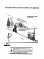
SLOPE OPERATION
o
Slopes are a major factor related to loss of control and
tipover accidents
which can result in severe injury or death
All slopes require extra caution
If you cannot back up the
slope or if you feet uneasy on it do not mow it
•
•
DO:
•
Mow up and down slopes, not across
•
Remove obstacles such as rocks, tree limbs, etc
•
Watch for holes, ruts, or bumps
Uneven terrain could
overturn the machine
Taft grass can hide obstacles
•
Use slow speed Choose a low gear so that you will not have
to stop or shift while on the slope
•
Follow the manufacturer's
recommendations
for wheel
weights or counterweights to improve stability
•
Use extra care with grass catchers or other attachments
These can change the stability of the machine
•
Keep all movement on the slopes slow and gradual Do not
make sudden changes in speed or direction
•
Avoid starting or stopping on a slope If tires lose traction
disengage the blades and proceed slowly straight down the
slope,,
•
•
°
•
portant
safety precautions.
It means
Look for this BECOME
CAUTIONI!!
symbol ALERTII!
to point out
YOUR
imSAFETY IS INVOLVED.
.L
i
n u.,ll.
I
n
I
I
.... DO N_OTL
•
•
•
CAUTION_ _Always.disconnect
spark
plug
................
Do not turn Onslopes unless necessa_ a_ th6n, fur#;_16_ly
and gradually downhill, if possible
Do not mow near drop offs ditches or embankments
The
mower could suddenly turn over if a wheel is over the edge
of a cliff or ditch, or il an edge caves in
Do not mow on wet grass° Reduced traction could cause
sliding
Do not try to stabilize the machine by putting your foot on the
ground
Do not use grass catcher on steep slopes
spark plug in order to prevent accidental
wire
and place
whereup,
it cannot
contact
starting
when wire
setting
transporting,
adjusting or making repairs.
,,,,,,,,,
,,,,,,,,,
iii
ii
ii
ii
iii
n,,,,,IJl
i,,,i,
iiii
i
I
i
& WARNING A
The engine exhaust from this product contains cl-iemicals known to the State of California to cause cancer, birth defects, or other
reproductive
harm.
iin
,,
i
inun, i iiii,J
Ji,,,,w
PRODUCT
CONGRATULATIONS
on your purchase of a Sears
Tractor° It has been designed, engineered and manufactured to give you the best possible dependability and
performance.
Should you experience any problem you cannot easily
remedy, please contact your nearest Sears Authorized
Service Center/Departmento
We have competent, we[F
trained technicians and the proper' tools to service or repair
this tractor_
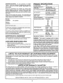
HORSEPOWER:
15.0
GASOLINE CAPACITY
AND TYPE:
1..25GALLONS
UNLEADED REGULAR
OIL TYPE (API-SF/SG/SH): SAE 10W30 (above 32°F)
SAE 5W-30 (below 32 F)
Please read and retain this manual The instructions will
enable you to assemble and maintain your tractor properly.
Always observe the "SAFETY RULES".
MODEL
NUMBER
SPECIFICATIONS
OiL CAPACITY:
W/FILTER:
4.0 PINTS
WiO FILTER: 3.5 PtNT8
SPARK PLUG:
(GAP: .040")
CHAMPION RC12YC
VALVE CLEARANCE:
NO-["ADJUSTABLE
GROUND SPEED (MPH):
FORWARD:
1st
2nd
3rd
4th
5th
6th
REVERSE:
TIRE PRESSURE:
FRONT:
REAR:
CHARGING SYSTEM:
3 AMPS BATTERY
5 AMPS HEADLIGHTS
BATTERY:
AMP/HR:
MIN, CCA:
CASE SIZE:
BLADE BOLT TORQUE:
30-35 FT_ LBS.
917.258543
SERIAL
NUMBER
DATEOFPURCHASE
THE MODEL AND SERIAL NUMBERS WILL BE FOUND
ON A PLATE UNDER THE SEAT.
YOUSHOULDRECORDBOTHSERIALNUMBERAND
DATE OF PURCHASE AND KEEP IN A SAFE PLACE
FOR FUTURE REFERENCE,
MAINTENANCE
AGREEMENT
A Sears Maintenance Agreement is available on this product. Contact your nearest Sears store for'details.
CUSTOMER
•
°
•
1_1
1.5
2,3
3.5
4,4
5.7
1.7
14 PSI
10 PSI
30
240
U1R
WARNING:
This tractor is equipped with an interna
combustion engine and should not be used on or near any
unimproved forest-covered, brush-covered or grass-cow
ered land unless the engine's exhaust system is equipped
with a spark arrester meeting applicable local or state taws
(if any)_ If a spark attester is used, it should be maintained
in effective working order by the operator.
In the state of California the above is required by law
(Section 4442 of the California Public Resources Code)°
Otherstates rnay have similar laws° Federal laws apptyon
federal land& A spark arrestor for the muffler is available
through your nearest Sears Authorized Service Cented
Department (See REPAIR PARTS section of this manual).
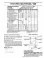
RESPONSIBILITIES
Read and observe the safety rutes.
Followa regularschedulein maintaining,caring forand
using your tractor.
Follow the instructions under"Customer Responsibilities" and "Storage" sections of this owner's manual.
i1
n,unn,,,,,,n,,=
I
u
LIMITED TWO YEAR WARRANTY ON CRAFTSMAN RIDING EQUIPMENT
For two(2) yearsfrom the date of purchase,if thisCraftsman Riding Equipment is maintained, lubricated and tuned up according to
the instructionsin the owner's manual, Sears will repairor replace, free of charge, any parts found to be defective in matedai or
workmanship.
This Warranty does not cover:
•
Expendable itemswhich become worn during normal use, such as blades, spark plugs, air cleaners, belts, etc;
•
Tire replacementor repair caused by puncturesfrom outsideobjects, such as halts, thorns, stumps, or glass.
,
Repairs necessary because of operator abuse negligence, improper'storage or accident or the failure to maintain the
equipment according to the instructions contained {n the owner's manual
•
Riding equipment used for commercialor renta! purposes.
LIMITED 90 DAY WARRANTY
ON BATTERY
:For- ninety-(90) days from date of purchase; if any battery included with this riding equipment_provesdefective _{n material or
workmanship and our testing determines the battery will not hold a charge, Searswill replace the battery at no charge..
IN-HOME WARRANTY SERVICE ON YOUR CRAFTSMAN RIDING EQUIPMENT iS AVAILABLE AT NO-CHARGE FOR 30 DAYS
FROM THE DATE OF PURCHASE. PLEASE CONTACT YOUR NEAREST SERVICE CENTER. AFTER 30 DAYS FROM THE
DATE OF PURCHASE, WARRANTY SERVICE 1SAVAILABLE BY TAKING YOUR CRAFTSMAN RIDING EQUIPMENT TO YOUR
NEAREST SEARS SERVICE CENTER. (IN-HOME WARRANTY SERVICE WiLL STILL BE AVAILABLE AFTER 30 DAYS FROM
THE DATE OF PURCHASE BUT A STANDARD TRiP CHARGE WiLL APPLY.) THIS WARRANTY APPLIES ONLY WHILE THIS
PRODUCT IS IN THE UNITED STATES.
This Warranty gives you specific legal rights, and you may also have ether rights which may vary from state to state_
SEARS, ROEBUCK AND CO., D/817 WA, HOFFMAN ESTATES, IL 60179
= 1,1 m m
11'="nHMUl
=
,'U
In U
=
ImH'l
TABLE OF CONTENTS
SAFETY RULES ............................................................
2
PRODUCT SPECIFICATIONS ...................................... 3
CUSTOMER RESPONSIBILITIES ..................... 3, 15-19
WARRANTY ..................................................................
3
TABLE OF CONTENTS ...............................................
4
ASSEMBLY ................................................................
7-9
OPERATION ............... ;...........................................
10-14
MAINTENANCE SCHEDULE ....................................... 15
SERVICE AND ADJUSTMENTS ............................ 20-25
STORAGE ...................................................................
26
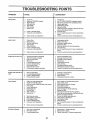
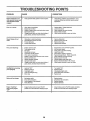
TROUBLESHOOTING .............................................. 27-28
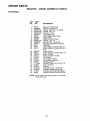
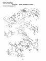
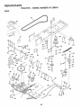
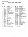
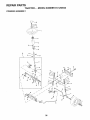
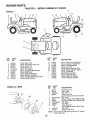
REPAIR PARTS - TRACTOR ................................. 30-47
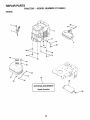
REPAIR PARTS- ENGINE .................................... 48-53
PARTS ORDERING/SERVICE .................. BACK PAGE
INDEX
A
Engine:
Operation.....................................
10-I4
Air Filter ...........................................
18
Operating Mower. ...............................
13
Air Screen .....................................
18
Options:
Cooling Fins, Engine .................... 18
Accessories ...............................................
5
Oil Change ..........................................
17
Spark Attester ...........................
3,40
Oil Level ..................................... 13,17
P
0iiType ...............................................
17
Parking Brake .....................................11-t2
Preparation
13
PartsBag ......................................
6
Repair Parts ...............................
48-53
Parts, Replacement/Repair
...............
30-47
Starting
..................................................
14
Product Specifications ............................
3
Storage ..................................................
26
R
F
B
Filters:
Repair Parts
30-47
Battery:
Air..................................................
18
S
Charging ......................................... 7
Fuel...................................................
19
Safety Rules ................................................2
Cleaning .............................................16
Fuel:
Seat ..........................................
8
Starting with Weak Battery .......... 23
Type .......................................................
13
Service
and
Adjustments
..................
20-25
Storage
26
Storage............................................
26
Brake ................................................. 22
Terminals
16
Fuse ..........................................
24
Carburetor
...................................
25
Belts:
G
Fuse ..................................................24
Motion Drive
Gauge Wheels ...........................................
8
Hood Removal/Insta!latien .............24
Removal/Replacement
...............
22
H
Motion Drive Belt
Mower Blade Drive
Hoed Removal/Installation ................. 24
Remova!/Replacement
............22
Removal!Replacement
........... 22
Mower Blade Drive Belt
L
Blade:
•Removal/Replacement
............
22
Leveling Mower Deck ..............................
21
Sharpening ..................................... 16
Mower
Adjustment:
Lubrication
Chart
15
Replacement ....................................16
Front-to-Back ..............................21
M
Brake Adjustment .......................................
22
Side-to-Side ................................21
Maintenance
Schedule
..........................15
C
Mower
Installation .............................
20
Mower:
Carburetor Adjustment ....................... 25
Mower Removal ..............................20
Adjustment, Front-to-Back .............21
Controls, Tractor .................................. 11
Tire Care ................................ 9,16,23
Adjustment, Side-to-Side .............. 2t
Customer Responsibilities .............. 15-19
Slope Guide Sheet .....................................
55
Blade
Sharpen
ng
.......................
16
Engine:
Spark
Plugs
..............................................18
Blade Replacement .................... 16
Air Filter. ........................................18
Specifications .......................................... 3
Cutting Height ......................................
12
Air Screen, Engine ..................... 18
Starting the Engine ..............................
13-14
Installation
20
Battery .......................................... t7
Steering Wheel ....................................7,23
Operation
............................................
t3
Cooling Fins, Engine ................. 18
Stopping the Tractor _..................................
12
Removal .................................................
20
Engine Oil ......................................
17
Storage
........................................
26
Mowing Tips ...............................................
14
Fuel Filter,
........................................
19
T
Muffler
_......................................................
18
Spark Plugs .................................18
Throttle Control Cable Adjustment ......25
Spark Arrester ............................. 3,40
Tractor:
Tires..........................................
9 16,23
............
...........................
9
....
Blades
:.........:.,:.;..Lo,:.o:16 ....MulcherPlate..,,,,,
0
Trouble Shooting Chart ......................27-28
Lubrication Chart ......................
15
Oil:
Maintenance Schedule ............ 15
Transaxle Repair Parts ......................46-47
Tire Care .:...................
9,t6,23
Cold Weather Conditions ..........14,17
W
Engine .............................................
t7
Cutting Height, Mower'. ......................... 12
Warranty ..........................................................
3
Storage
26
E
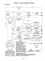
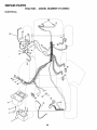
Wiring Diagram ...................................... 30
Electrical:
Wiring Schematic ....................................29
Accessories ...........................................
5
Adjustments:
Brake ................................................ 22
Carburetor ..................................... 25
Mower:
Front-To-Back .......................... 21
Side-To-S_de ............................ 21
Throttle Control Cable ................. 25
Air Filter, Engine
t8
Air Screen, Engine ................................. 18
Assembly
7-9
......................................
.....................................
..................................................
.....................................
..............................................
.........................................
........................................
............................................
k;_Z.,
........
..............................................
Interlocks and Relays .....................24
Schematic .............................................
29
Wiring Diagram
30
...............................
i IH,,,,I,,II
nl
,,,,,,,,,,
,,,,,,,
ACCESSORIES
iiiiiiiiiiiiiiiiiii
iii
iiiiiiiiiiiii
i
lUl
II1,111111111
lUln
I!
nnn
in
nl
nlnn,
AND ATTACHMENTS
iiiiiii
iii
......
ii
iiiiiiiiiiiiiiiiiiiii
i
iiiiiiiiiiiii
i
i
iiiiiiiiiiiii
These accessories and attachments we re available through most Sears retail outlets and service centers when the tractor was purchased..
Most Sears stores can order these items for you when you provide the model number' of your tractor°
ENGINE
SPARK PLUG
MAINTENANCE
GAS CAN
ENGINE OIL
FUEL STABILIZER
AIR FILTER
BLADES
BELTS
PERFORMANCE
Sears offers a wide variety of attachments that fit your tractor. Many of these are tisted below with brief explanations of how they can help
you. This list was current at the time of publication; however, it may change in future years - more attachments may be added, changes
may be made in these attachments, or some may no tonger be available or fit your model Contact your nearest Sears store for the
accessories and attachments that are available for your tractor.
Most of these attachments do not require additional hitches or conversion kits (those that do are indicated) and are designed for easy
attaching and detaching
SNOW BLADEfor snowremovalonly.
14-inch high,48-1nchwide
btade clears 424nch path when angledteft or righL Raises, lowers
with side lever_. Adjustable skids; replaceable, reversible scraper
bar. (Use with tire chains and wheel weights and/or rear drawbar
weight )
SNOWTHROWER has 40-inch swath. Drum4ype auger handles
powdery and wet/heavy snow_ Mounts easily with simple pin
arrangement. Discharge chute adjusts from tractor seat. 6-inch
diameter spout discharges snow 10 to 50 feet. Lift controlled at
tractor seat. (Use with chains and wheel weights and/or rear
drawbar weight.)
SPRAYERS use 12-volt DC electric motor that connects to the
tractor battery or other 12-volt source
Includes booms for
automatic spraying and hand held wand for Spot spraying. Wand
has adjustable spray pattern. For applying herbicides, insecticides, fungicides and liquid fertilizers.
SPREADEPJSEEDERS make seeding, fertilizing, and weed kitl}ng easy, Broadcast spreaders are also useful for granular detcefs and sand..
AERATOR promotes deep root growth for a healthy lawn. Tapered 2 54nch steel spikes mounted on 10-inch diameter discs
puncture holes in soil at close intervals to let moisture soak in..
Steel weight tray for increased penetration.
BAGGER iets you collect
grass clippings and leaves for a
healthier, nearer looking lawn. Two Permanex containers hold
30-gallon plastic bags.
BUMPER protects front end of tractor from damage_
CARTS make hauling easy. Variety of sizes available, plus
accessories such as side panel kits, tool caddy, cart cover,
protective mat and dolly.
CORING AERATOR takes small plugs out of soil to allow moisture and nutrients to reach grass roots
36-inch swath° 24
hardened steel coring tips. 1501b capac{tyweighttray_
EASY OIL DRAIN VALVE makes oil changes easier, faster_
FRONT NOSE ROLLER canters in front of mower deck to reduce
chances of "scalping" on uneven terrain.
GANG HITCH lets you tow 2 or 3 pull-behind attachments at once,
such as sweepers, dethatchers, aerators (not for' use with roUers,
carts or other heavy attachments).
GAUGE WHEELS on both sides of the mower deck reduce
chances of "scalping" on uneven terrain_ For mower decks not so
equipped.
MULCH RAKE/DETHATCHER
loosens soil and flips thatch and
matted leaves to lawn surface for easy pickup. Twenty spring tine
teeth.. Uselultopreparebareareasfcrseeding,
Availableforfront
or rear mounting.
HIGH PERFORMANCE
REEL-ACTION
SPRING TINE DETHATCHER covers 36-inch wide path and
tosses thatch into large hopper. Mounts behind tractor.
SWEEPERS let you collect grass clippings and leaves_
TILLER has 5 hp engine and 36-inch swath to prepare seed beds,
cultivate and compost garden residue. Tiller has its own built-in
lift and depth control system and does NOT require a sleeve hitch_
Fits any lawn, yard or garden tractor. Simply hook up tothe tractor
drawbar and go!
Optional
accessories
convert unit for
dethatching, aerating, hil_ing.o.witheut tools.
TIRE CHAINS are heavy duty closely spaced extra-large cross
links give smooth ride, outstanding tractlon_
TRACTOR CAB has heavy duty vinyl fabric over tubular steel
f_ame, ABS plastic top; clear plastic windshield offers 360 degree
visibility. Hinged metal doors with catch. Keeps operator warm
and dry. Remove vinyl sides and windshields for use as sun
protector in summer.. Optional accessories
include,
tinted/
tempered solid safety glass windshield with hand operated wiper;
12_volt amber, caution light for mounting on cab top.._
VACS for powerful co!lection of heavy grass clippings and {eaves°
Optional wand attachment to pick up debris in hard4o-reach
places. VAC/CHIPPER includes a chipper-shredder.
WEIGHT BRACKET for drawbar for snow removal applications..
Uses (1) 55 Ib. weight.
WHEEL WEIGHTS for' rear wheels provide needed traction for
snow removal or dozing heavy material&
MULCHING CLOSE-OUT PLATE KIT, once installed, lets you
mulch, discharge or bag clippings (bagger optional) without
changing blades, For models not equipped as 3-in-1 Convertible
mowers.
See "MOWER" in the Repair Parts section of this
manual .........
RAMP TOPS AND FEEl" let you load and unload tractor from a
pickup truck. Use with 2 x 8 or 2 x 10 lumber.
ROLLER for smoother lawn surface.
36-inch wide, 18-inch
diameter water-tight drum holds up to 390Ibs. of weight.. Rounded
edges prevent harm to turf. Adjustable scraper automatically
cleans drum.
5
i ,,,, ....
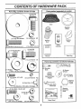
CONTENTS
i1,1,,i
.....................
_
OF HARDWARE
"",,
..........
PACK
Parts Bag contents shown full size
(1) Hex Bolt
3/8-16 x 1
©
Seat
Steering
Wheel
G
(t) Lockwasher
(1) Large Flat Washer
3/8
Mulcher
Plate
Steering
Boot
Video
Cassette
(1) Lecknut 5/16_18
(1) Hex Bolt 5/16-18 x 1-1/4
..........
,11
....................
t
-J
(1) Hex Bolt
1/2-13 x t
5/16-18
i
!
I
t
.........
(1) Shoulder Bolt
[_
[
-._
i i,i i, i
Hill
Parts bag contents
=z_
_r
=__x
T
Parts Bag
Manual
, ,i,,,111 i
(1) Lock Washer 1/2
III1'
not shown full size
i,,
ii
,i i,iiii
x2)7/8
x 14 Gauge
Washers
3/8
(1) Was
(2) Shoulder
Bo}ts
17/32 x 1-3/16 x 12 Gauge
i
_ws
iii,
,111
#10 x 5/8
Wheels
(2) Center (2) Gauge
lock Nuts
i,i,
(2) Lock Washers
Steering Wheel
Adapter
#10
Swteering
heel
Insert
(2) Latch Hook
Assemblys
Steering
--- Extension
Shaft
(2) Hex Bolts 1/4-20 x 3/4
(2) Hex Nuts
o
(2) Washer,, _
_
-
!/4-20
SJope Sheet
9/32 x 5/8 x 16 Gauge
12) Lock Washers
1/4
6
(2) Keys
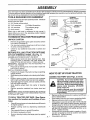
ASSEMBLY
= nn
mnH
n= ,,Hi =
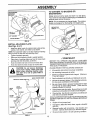
Your new tractor has been assembled at the factory with exception of those parts {eft unassembled for shipping purpose&
To ensure safe and proper operation of your tractor all parts and hardware you assemble must be tightened securely. Use
the correct tools as necessary to insure proper tightness,
TOOLS REQUIRED
FOR ASSEMBLY
STEERING
A socket wrench set will make assembly easier, Standard
wrench sizes are listed.
__._
(1) 3/4" Socket w/drive rachet
(2) 7/16" wrenches
(1) Phillips Screwdriver
(2) 1/2" wrenches
Tire pressure gauge
(1) 9/16" wrench
Utility knife
When right or left hand is mentioned in this manual, it
means when you are in the operating position (seated
behind the steering wheel),
TO REMOVE TRACTOR
UNPACK
STEERING
FROM CARTON
CARTON
•
Remove all accessible loose parts and parts cartons
from carton (See page 6).
•
Cut, from top to bottom, along lines on all four'corners
of carton, and lay panels flat.
Check for any additional loose parts or cartons and
remove.
•
318LOCKWASHER
BOOT
EXTENSION
SHAFT
'_
ADAPTER
5tl 6 HEX BOLT
BEFORE ROLLING TRACTOR OFF SKID
ATTACH
ASSEMBLE
STEERING
WHEEL
(See Fig, 1)
EXTENSION SHAFT AND BOOT
°
Slide extension shaft onto lower steering shaft., Align
mounting holes in extension and lower shafts and
install 5/16 hex bolt and locknut. Tighten securely.
IMPORTANT; TIGHTEN BOLT AND NUT SECURELY TO
18-22 FT LBSTORQUEr
•
Place tabs of steering boot over tab slots in dash and
push down to secure,
INSTALL STEERING WHEEL
•
Position front wheels of the tractor so they are pointing
straight forward.,
•
Slide steering wheeladapteronto
steering shaft extension,
•
Position steering wheel so cross bars are horizontal
(left to right) and slide inside boot and onto adapter°
•
Assemble large flat washer, 3/8 tock washer, 3/8 hex
bolt and tighten securely.
•
Snap steering wheel insert into center of steering
wheel,
°
Remove protective materials from tractor hood and
grill.
IMPORTANT, CHECK FOR AND REMOVE ANY STAPLES
IN SKID THAT MAY PUNCTURE TIRES WHERE TRACTOR
IS TO ROLL OFF SKID,
TO ROLL TRACTOR
OFF:SKID
(See Operation section for location and function of controls)
•
Press lift lever' plunger' and raise attachment lift lever to
its highest position.
•
•
•
Release parking brake by depressing clutch/brake
pedal.
Place gearshift lever in neutral (N) position..
Roll tractor backwards off skid.
°
Remove banding holding discharge guard up against
tractor.
......
FIG. 1
HOW TO SET UP YOUR TRACTOR
CONNECT
,,
BATTERY
,
(See Figs. 2 and 3)
,tit
CAUTION:
ii
Do not short battery termi-
object to contact both terminals at the
nals
by allowing
or any
other
sametime.
Beforea wrench
connecting
battery,
remove metal bracelets, wristwatch
bands, rings, etc.
Positive terminal must be connected
first to prevent sparking from accidental grounding.
•
°
•
°
•
7_."
Remove cardboard packing from seat pan and !ift seat ....
pan to raised positiorL
Open battery box door and remove protective plastic,
Remove terminal protective caps and discard_
If this battery is put into service after month and year
indicated on label (label located between terminals)
charge battery for minimum of one hour at 6-10 amps,
First connect RED battery cable to positive (+) terminal
with hex bolt, flat washer, lock washer and hex nut as
shown. Tighten securely.
Connect BLACK grounding cable to negative (-) terminal with remaining hex bolt, flat washer, lock washer'
and hex nut° Tighten securely.
Close battery box door.
ASSEMBLY
...... ,,,.,,
Open battery box door for':
•
Inspection for secure connections
ware).
•
inspection for corrosion.
•
Testing battery.
•
Jumping (if required).
•
Periodic charging.
(to tighten hard-
SEAT
SEAT PAN
SHOULDER
BOLT
DISCARD
TERMINAL
PROTECTIVE
_
LOCK
WASHER
CAPS
FLAT
WASHER
i
i
LARGE FLAT WASHER
ADJUSTMENT
BOLT
LOCK WASHER
FIG. 4
CHECK TiRE PRESSURE
HEX
BOLT
POSITIVE
/
(RED) CABLE
The tires on your tractor were overinflated at the factory for
shipping purposes_ Correct tire pressure is important for
best cutting performance.
NEGATIVE
(BLACK)CABLE
=
FIG, 2
Reduce tire pressure to PSI shown in "PRODUCT
SPECIFICATIONS" on page 3 of this manual.
CHECK
DECK LEVELNESS
For best cutting results, mower housing should be properly
leveled. See "TO LEVEL MOWER HOUSING" in the
Service and Adjustments section of this manual
SEAT
PAN
CHECK
BELTS
BATTEI
BOXDOOR
FOR PROPER
POSITION
OF ALL
See the figures that are shown for replacing motion and
mower blade drive belts in the Service and Adjustments
section of this manual
Verify that the belts are routed
correctly.
CHECK
INSTALL
SEAT (See Fig. 4)
Adjust seat before tightening adjustment bolt,,
.
Remove cardboard packing on seat pan.
Place seat on seat pan and assemble shoulder bolt.
•
Assemble adjustment boit, lock washer and flat washer
loosely Do not tiahten
"'
"
.....................
Tighten shoulder' bolt securely.
o
•
Lower seat into operating position and sit on seat°
Slide seat until a comfortable position is reached which
allows you to press clutch!brake pedal all the way
down.
•
Get off seat without moving its adjusted position.
•
Raise seat and tighten adjustment bolt securely.
SYSTEM
After you learn how to operate your tractor, check to see
that the brake is properly adjusted_ See "TO ADJUST
BRAKE" in the Service and Adjustments section of this
manual,
FIG, 3
•
BRAKE
ASSEMBLE
GAUGE
DECK (See Fig. 5)
WHEELS
TO
MOWER
The gauge wheels are designed to keep the mower deck in
......
,= ....
e- -re
proper' posmon when opera_mg moW_to _e sure m y a
pr0per'lyadjusted to ensure optimum mower •performance.
•
Assemble gauge wheels with tractor on a flat level
surface.
°
°
8
Adjust mower to desired cutting height (See "TO ADJUST MOWER CUTTING HEIGHT' in the Operation
section of this manual).
With mower in desired height of cut position, gauge
wheels should be assembled so they are slightly off the
ground. Install gauge wheel in appropriate hole with
shoulder bolt, 3/8 washer, and 3/8-16 locknut and
tighten securelyo
Repeat for opposite side installing gauge wheel in
same adjustment hole.
ii
=l=lll_
= .........
i= i
lUlH
....................
='"="='
ASSEMBLY
ii
ii IIIIIIIIIIIIHIII
III
q
iiii
miNI,
m NI,
.......................
II
TO CONVERT TO BAGGING OR
DISCHARGING
GAUGE WHEEL
MOUNTING
BRACKET
Simply remove mulcher plate and store in a safe place.
Your mower is now ready for discharging or installation of
optional grass catcher accessory.
NOTE: it is not necessary to change blades The mutcher
blades are designed for discharging and bagging also.
DEFLECTOR
3/8-16
LOCKNUT
318" WASHER
jSHOULDER
GAUGEWHEEL"
BOLl'
"%
FIG, 5
INSTALL MULCHER
(See Figs. 6 & 7)
•
PLATE
Install two latch hooks to mulcher plate using screw,
washer, lock washer, and weld nut as shown.
LATCH
HOOKS
NOTE: Pro-assemble weld nut to latch hook by inserting
weld nut from the top with hook pointing down.
•
Tighten hardware securely.
•
Raise and hold deflector shield in upright position.
•
Place front of mulcher plate over front of mower deck
opening and slide into place, as shown
•
Hook front latch into hole on front of mower deck_
•
Hook rear latch into hole on back of mower deck.
i
i
i
,i ,i
i,i1,1,1,111111
ii
iiii
FIG. 7
,/CHECKLIS
T
BEFORE YOU OPERATE AND ENJOY YOUR NEW
TRACTOR, WE WISH TO ASSURE THAT YOU RECEIVE
THEBES T PERFORMANCE AND SA TISFA C TION FROM
THIS QUALITY PRODUCT.
i iiiiii
PLEASE REVIEW THE FOLLOWING
guard from mower. Raise and hold
guard
whenDoattaching
mulcher
plate
CAUTION:
not remove
discharge
and allow it to rest on plate while in
operation,
='1 M=
,,
i
iii iiiiil!l!lll
iiii iiiii
HOOKPOINTSDOWN
WELD NUT FROM
TH_
CHECKLIST,
,/
All assembly instructions have been completed.
,/"
No remainJng loose parts in carton.
,/
Batteryis property prepared and charged.
t hour at 6 amps).
7
Seat is adjusted comfortably and tightened securely.
,/
All tires are properly inflated. (For shipping purposes,
the tires were ovennflated at the factory).
,/
Be sure mower deck is properly leveled side-to-side/
front-to-rear for best cutting resultS: (Tires must be
properly inflated for leveling).
,/
Check mowerand drive belts. Be sure they are routed
properly around pulleys and inside all belt keepers.
WELD
(Minimum
,/
Check wiring_ See that all connections are still secure
and wires are properly clamped.
WHILE LEA RN/NG NO W TO use YOUR TRACTOR, PAY
EXTRA ATTENTION TO THE FOLLOWING IMPORTANT
ITEMS:
....
LATCH
HOOK
LOCK
WASHER
WASHER
WELD
NUT
Fuel tank is filled with fresh, clean, regular unleaded
gasoline.
Become familiar with atl controls - their location and
function. Operate them before you start the engine.
v"
_...---_SCREW
FIG. 6
Engine oil is at proper level°
,/
v"
WASHER
MULCHER
PLATE
,/
9
Be sure brake system is in safe operating condition.
i,
.
. ..................
_
u
.
nl
i¸
'
i
n ii,
u i,i
.........
,,-
,,.
., ....
_
_.".i=,
......
=,,
n
OPERATION
These symbols may appear on your tractor or in literature sLtppUedwith the product. Learn and understand their meaning,
÷
BATTERY
CAUTION OR
WARNING
REVERSE
FORWARD
FAST
SLOW
ENGINE ON
ENGINE OFF
OIL PRESSURE
CLUTCH
LIGHTS ON
LIGHTS OFF
FUEL
CHOKE
MOWER HEIGHT
DIFFERENTIAL
LOCK
PARKING BRAKE
LOCKED
UNLOCKED
L
REVERSE
MOWERLI_
NEUTRAL
ATTACHMENT
CLUTCH ENGAGED
HIGH
LOW
ATTACHMENT
CLUTCH DISENGAGED
PARKING BRAKE
IGNITION
HYDROSTATIC FREE WHEEL
(Hydro Models only)
DANGER, KEEP HANDSANDFEETAWAY
10
=l i==
illll=i=ii,i
ii
i I==IH
i, =ll,
H ill
OPERATION
ijj
I!ll
iii iiiiiiiiii
i
i
ii
II
iiii
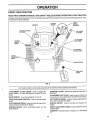
KNOW YOUR TRACTOR
READ THIS OWNER'S MANUAL AND SAFETY RULES BEFORE OPERATING YOUR TRACTOR
Compare the illustrations with your tractor to familiarize yourself with the locations of various controls and adjustments. Save
this manual for future reference.
IGNITIO N
SWITCH
AMMETER
THROTTL_CHOKE
CONTROL
LIGHT
SWtTC H
POSITION
LIFT LEVER
PLUNGER
©
CLUTCH/
BRAKE
PEDAL
ATTACHMENT
LIFT LEVER
ATTACHMENT
CLUTCH LEVER
HEIGHT
ADJUSTMENT
KNOB
PARKING
BRAKE
GEARSHIFT
LEVER
FIG. 8
Our tractors conform to the safety standards of the American National Standards Institute.
GEAR SHIFT LEVER - Selects the speed arid direction of
the tractor_
ATTACHMENT CLUTCH LEVER: Used to engage the
mower blades, or other attachments mounted to your'
tractor.
LIGHT SWITCH:
ATTACHMENT LIFT LEVER: Used to raise and lower the
mower deck or other' attachments mounted to yourtractor,.
Turns the headlights on and off.
Used to control engine
LIFT LEVER PLUNGER: Used to release attachment lift
lever when changing its position.
CLUTCH/BRAKE PEDAL: Used for declutching and braking the tractor and starting the engine.
IGNITION SWITCH: Used for starting and stopping the
engine,
HEIGHT ADJUSTMENT KNOB; Used to adjust the mower
cutting height,
THROTTLE/CHOKE
speed.
PARKING BRAKE:
brake position_
CONTROL:
Locks ctutch,_rake
pedal into the
AMMETER:
(-)_
11
Indicates battery charging (+) or discharging
OPERATION
I
I
_ ,_u==
_
I
_
]
The operation of any tractor can result in foreign object s thrown into the eyes, which can
resultin severeeyedamage.
Alwayswearsafetyglassesoreyeshieldswhile
operatingyour
tractor or performing any adjustments or repairs, We recommend a wide vision safety mask
over the spectacles or standard safety glasses.
NOTE: Under certain conditions when tractor is standing
idle with the engine running, hot engine exhaust gases may
cause "browning" of grass. To eliminate this possibility,
always stop engine when stopping tractor on grass areas.
HOW TO USE YOUR TRACTOR
TO SET PARKING
BRAKE
(See Fig. 9)
Your'tractor'is equipped with an operator presence sensing
switch. When engine is running, any attempt by the
operator to leave the seat without first setting the parking
brake will shut off the engine.
•
Depress clutch/brake pedal into full "BRAKE" position
and hold_
*
Place parking brake tever in"ENGAGED" position and
release pressure from clutch/brake pedaL Pedal should
remain in "BRAKE" position° Make sure parking brake
wilt hold tractor secure°
pletely, as described above, before leavCAUTION:
ing
the operator's
Always position;
stop tractor
to empty
corngrass catcher, etc,
TO USE THROTrLE
ATTACHMENT CLUTCH LEVER
"ENGAGED" POSITION
THROTTLE/CHOKE
COI_TROL
PARKING BRAKE
"ENGAGED"
Operating engine at less than full throttle reduces the
battery charging rate.
,
Full throttle offers the best bagging and mower performance.
HEIGHT ADJUSTMENT
KNOB
•
Start tractor with dutch/brake pedal depressed and
gearshift lever in neutral (N) position.
•
Move gearshift lever to desired
TO ADJUST MOWER
(See Fig. 9)
FIG. 9
Move attachment clutch lever to "DISENGAGED"
sition.
po-
_
Move throttle control to slow (=l_)
HEIGHT
Turn knob c{ockwise ((_4)
position.
NOTE: Failure to move throttle control to slow (,_,)
position and allowing engine to idle before stopping may
cause engine to "backfire".
•
Turn ignition key to "OFF" position and remove key.
Always remove key when leaving tractor to prevent
unauthorized use.
,
Never use choke to stop engine.
to raise cutting height,,
-
Turn knob counterclockwise
height.
(_)to
lower cutting
The cutting height range is approximately ! -1/2" to 4". The
heights are measured from the ground to the blade tip with
the engine not running. These heights are approximate
and may vary depending upon soit conditions, height of
grass and types Of grass being mowed.
Depress clutch/brake pedal into fuII"BRAKE" position.
_ :.Mov e gearshift _ lever to neutral (N) posit!0n_
ENGINE •
CUTTING
•
GROUND DRIVE *
,
position.
The cutting height is controlled by turning the height adjustment knob in desired direction.
(See Fig. 9)
MOWER BLADES •
is controlled by the
•
Slowly release clutch/brake pedal to start movement.
IMPORTANT: BRING TRACTOR TO A COMPLETE STOP
BEFORE SHIFTING OR CHANGING GEARS. FAILURE
TO DO SO WILL SHORTEN THE USEFUL L{FE OF YOUR
TRANSAXLE
"DISENGAGED"
POS_ION
STOPPING
AND BACKWARD
The direction and speed of movement
gearshift lever.
GEARSHIFT
CLUTCH/BRAKE
PEDAL "DRIVE"
POSITION
(See Fig. 9)
•
TO MOVE FORWARD
(See Fig. 9)
_'BRAKE"
POS_ION
CONTROL
Always operate engine at full thrott{e
12
.
The average lawn should be cutto approximately 2-1/2
inches during the cool season and to over 3 inches
dudng hot months. For healthier and better looking
lawns, mow often and after' moderate growth.
•
For' best cutting performance, grass over 6 inches in
height should be mowed twice. Make the first cut
relatively high; the second to desired height,
L
I
ii ,11 MI N,
=::_
::_
.................
,1
, .....
=_
OPERATION
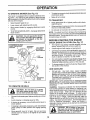
TO OPERATE
MOWER
(See Fig. 10)
Your'tractor [s equipped with an operator presence sensing switch, Any attempt by the operator to leave the seat
with the engine running and the attachment clutch engaged
will shut off the engine.
*
o
Select desired height of cuL
Lower mower with attachment lift control.
.
Start mower blades by engaging attachment clutch
control.
o
TO STOP MOWER BLADEScrutch control.
=ll
L
ii
,,
ii
iiii
iiu
•
Make all turns slowly_
o
Raise attachment lift to highest position with attachment lift control.
•
When pushing or towing your tractor, be sure gearshift
lever is in neutral iN) position°
•
Do not push or tow tractor at more than five (5) MPH_
NOTE: To protect hood from damage when transporting
your tractoron a truck or a trailer, be su re hood is closed and
secured to tractoL Use an appropriate means of tying hood
to tractor (rope, cord, etc.).
ii
without either the entire grass catcher,
CAUTION:
operate or
thethe
mower
on
mowers Do
so not
equipped,
discharge guard in place.
,11
To restart movement, slowly release parking brake and
clutch/brake pedal.
TO TRANSPORT
disengage attachment
.......................................
•
BEFORE STARTING
CHECK
ATTACHMENT
CLUTCH
LEVER "DISENGAGED"
"ENGAGED"
POSITION \
POSITION
_
_/_
ADJUSTMENT
_._/
t
r
i_
/k_//
,/
ATTACHMENT
HIGH POSITION
!
THE ENGINE
i
/''
ENGINE OIL LEVEL
(See Fig. 17)
•
The engine in your tractor has been shipped, from the
factory, already filled with summer weight oil..
-
Check engine oil with tractor on level ground°
•
Unthread and remove oil fill cap/dipstick; wipe oil off.
Reinsert the dipstick intothe tube and rest oil fill cap on
the tube. Do not thread the cap onto the tube. Remove
and read oil level if necessary, add oil until "FULL"
mark on dipstick is reached. Do not overfill
.
For cold weather operation you should change oil for
easier' starting (See OiL VISCOSITY CHART' in the
Customer Responsibilities section of this manual),
•
To change engine oil, see the Customer Responsibilities section in this manual.
ADD GASOLINE
.
/
I
_
Fill fuel tank_ Use fresh, clean, regular unleaded
gasoline with a minimum of 87 octane. (Useof leaded
gaso(ine will increase carbon and lead oxide deposits
and reduce valve life). Do not mix oil with gasoline.
Purchase fuel in quantities that can be used within 30
days to assure fuel freshness,
IMPORTANT: WHEN OPERATING IN TEMPERATURES
BELOW 32°F(0°C), USE FRESH, CLEAN WINTER GRADE
GASOLINE TO HELP INSURE GOOD COLD WEATHER
STARTING.
GUARD
FIG. 10
TO OPERATE
ii
i ml,l,i
•i
_#_
_
,,_
Ul, I
......
ON HILLS
,iH i,l,,,i,t
ii ,,N,N
WARNING:
Experience indicates that alcohol blended
fuels (called gasohot or using ethanol or methanol) can
attract moisture which leads to separation and formation of
acids during storage. Acidic gas can damage the fuel
system of an engine while in storage. To avoid engine
problems, the fuel system should be emptied before stor•age 0f 30 days or Idrtger. ' Di'a:[_ the _tas ta;nk; st-art the
engine and let it run untit the fuel lines and carburetor are
empty. Use fresh fuel next season. See Storage Instructions for addit]onat information.
Never use engine or
carburetor cleaner products in the fuet tank or permanent
damage may occur.
Nl'l
CAUTION:
Do not drive up or down
hills with slopes greater than 15 ° and
do not drive' across
any slope,
I I H'H I ,,,,,,,,,,,,,,,
,,,,
I
I
_, - Choose the slowest speed before starting up or down
hills.
•
Avoid stopping or changing speed on hills.
•
If slowing is necessary, move throttle control lever to
slower position.
•
If stopping is absolutely necessary, push clutch/brake
pedal quickly to brake position and engage parking
brake.,
•
Move gearshift lever to 1st gear'. Be sure you have
aIIowed room for' tractor' to roll slightly as you restart
movement.
'NI
t
i .....
filler neck. Do not overfill Wipe off any
spilled
oil orFill
fuel to Do
not store,
spill
or
AUTION:
bottom
of gas
tank
use gasoline near an open flame.
i_
................
13
HI",
I,=H
i
i
'
=...............
,_
i
OPERATION
TO START ENGINE (See Fig. X)
•
When starting the engine for the first time or' if the engine
has run out of fuel, it will take extra cranking time to move
fuel from the tank to the engine.
Do not mow grass when it is wet. Wet grass will plug
mower and leave undesirable clumps. Allow grass to
dry before mowing.
•
Always operate engine at full throttle when mowing to
assure better mowing performance and proper discharge of material., Regulate ground speed by selecting a low enough gear' to give the mower cutting
performance as wetl as the quality of cut desired.
•
When operating attachments seiect a ground speed
that wilt suit the terrain and g ve best performance of
the attachment being used.
•
Sit on seat in operating position, depress clutch/brake
pedal and set parking brake.
•
Place gear' shift lever in neutral iN) position.
•
Move attachment clutch to "DISENGAGED"
position.
•
Move throttle control to choke iN) position°
Note: Before starting, feed the warm and cold starting
procedures below.
•
f
it(
Insert key intoignition and turn key clockwise to"START"
position and release key as soon as engine starts° Do
not run starter continuously for more than fifteen seconds per minute_ If the engine does not start after
several attempts, move throttle control to fast (,f_)
position, wait a few minutes and try again. If engine still
does not start, move the throttle control back to the
choke iN) position and retry.
WARM WEATHER STARTING (50 ° F and above)
=
When engine starts, move the throttle controlto the fast
(,t_) position.
.
Th/a attachments and ground drive can now be used. If
the engine does not accept the load, restart the engine
and allow it to warm up for one minute using the choke
as described above.
COLD WEATHER STARTING
FIG, 11
MULCHING
( 504 F and below)
•
When engine starts, allow engine to run with the throttle
control in the choke (XI) position until the engine runs
roughly, then move throttle control to fast (.tl_) position,,
This may require an engine warm-up period from
several seconds to several minutes, depending on the
temperature.
•
The attachments can also be used during the engine
warm-up period°
NOTE: If at a high altitude (above 3000 feet) or in cold
temperatures (below 32 F) the carburetor fuel mixture may
need to be adjusted for' best engine performance. See "TO
ADJUST CARBURETOR" in the Service and Adjustments
section of this manual..
MOWING TIPS
•
•
Mower should be ,properly leveled for
performance. See TO LEVELMOWER
the Service and Adjustments section of
The left hand side of mower' should be
ming.
best mowing
HOUSING" in
this manual.
used for trim-
..
Ddve so that clippings are discharged onto the aFea
that has been cut. Have the cut area to the right of the
machine. This wilt result in a more even distribution of
clippings and more uniform cutting_
•
When mowing large areas, start by turning to the right
so that clippings will discharge away from shrubs,
fences, driveways, etc. After one or two rounds, mow
in the opposite direction making left hand turns until
finished (See Fig. 11 ),,
-
If grass is extremely tall, it should be mowed twice to
reduce load and possible fire hazard from dried clippings. Make first cut relatively high; the second to the
desired height,.
MOWING
TiPS
IMPORTANT:
FOR BEST PERFORMANCE,
KEEP
MOWER HOUSING FREE OF BUILT-UP GRASS AND
TRASH. CLEAN AFTER EACH USE.
•
The special mulching blade wilt recut the glass clippings many times and reduce them in size so that as
they fall onto the lawn they will disperse into the grass
and not be notice&
Also, the mulched grass will
biodegrade quickly to provide nutrients for the lawn.
Always mulch with your' highest engine (blade) speed
as this will provide the best recurring action of the
blades.
•
Avoid cutting your lawn whenit iswet. Wet grasstends
to form ctumps and interferes with the mulching action.,
The best time to mow your' lawn is the early afternoon,,
At this time the grass has dried and the newly cut area
will not be exposed to the direct sun,
•
For best results, adjust the mower cutting height so that
the mower cuts off only the top one-third of the grass
blades (See Fig. 12). For extremely heavy mulching,
reduce your width of cut and mow slowly.
•
Certain types of grass and grass conditions may require that an area be mulched a second time to completely hide the clippings,. When doing a second cut,
mow across or perpendicular to the first cut path.
•
Change your cutting pattern from week to week. Mow
north to south one week then change to east to west the
nex_waek_ This will help prevent matting and graining
of the lawn.
MAX 1/3
14
FIG, 12
i,,u,,,i,
i
u,,i,,_lqqllll
i i
CUSTOMER
inunllUUl
in'ill
¸ ' i iii
u
i
i
RESPONSIBILITIES
i lU i i
i
i
...........................................................
MA,NTENANCE
SC.EDuLE
.....
F,LL,N
DATES
-
AS YOU COMPLETE
T
Check BrakeOperation
CheckTire Pressure
Checkfor LooseFasteners
i Sharpen/Rep
lace Mower
LubricationChart
i
T
I_
,,
Btades
Check Battery LeveVRecharge
0 ,,C_ean
Ba_e_
andTerminal.
R
Check Transaxle
V_
!V'
V'
Cooling
V _
V#5
Adjust Motion Drive Belt(s) Tension
v',
v' v'
ChangeEngineOit
CleanAir Filler
v"_
N
,CleanAir screen
G
Inspect MuffledSparkArrester
I
1_4
Irl/
I, V_
Adjust Blade Belt(s) Tension
Check Engine Oil Level
E
!v'
If
Replace
v"
_2
VS
V' V'
Oil Fijter (If equipped)
Clean Engine Cooling Fins
ReplaceSparkPIug
Replace
Air Filter Paper
Cartridge
v'
ReplaceFuelFiite{
t .. Change mote ellen when operating under a heavy load ot in high ambient temperatures
2 o Service more often when operating in dirty or dusty conditions
3 .. Ifequipped with oil filter, change oitevery 50 hours
4. Replace b)ades more eltan when mowing in sandy se()
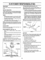
GENERAL
5 - Ir equipped with adiustabie system
6 - Not required Ifequipped with maintenance*free battery.
7 - Tlghlen front axle pivot bolt to 35 It-Ibs maximum
Do not evert{ghten
LUBRICATION
RECOMMENDATIONS
The warranty on this tractor does not cover items that have
been subjected to operator' abuse or negligence.
To
receive full value from the warranty, operator' must maintain
tractor as instructed in this manual,.
®
CHART
_DLE ZERK (_)
..=%
FRONT WHEEL
BEARING ZERK
Some adjustments will need to be made periodically to
properIy maintain your' tractoL
All adjustments in the Service and Adjustments section of
this manual should be checked at least once each season.
•
•
Once a year you should replace the spark plug, clean
or replace air filter, and check blades and belts for
wear. A new spark plug and clean air filter assure
proper' air-fuel mixture and help your engine run better
and last longer.
..........
-
BEFORE
®
(_
CLUTCH
. P.IVOT(S)
EACH USE
•
Check engine oilteveL
•
Check brake operation_
•
Check tire pressure.
•
Checkfor
loose fasteners.
PIVOTS
(_) SAE30 OR10W30MOTOROIL
(_ GENERALPURPOSEGREASE
(3) REFERTOCUSTOMERRESPONSIBILITIES
"ENGINE"SECTION
IMPORTANT: DO NOT OIL OR GREASE THE PIVOT POINTS
WHICH HAVE SPECIAL NYLON BEARINGS, VISCOUS LUBRICANTSWiLL ATTRACT DUST AND DIRT THAT WILL SHORTEN
THE L(FE OF THE SELF-LUBRiCATING BEARINGS. IF YOU
FEEL THEY MUST BE LUBRICATED, USE ONLY A DRY, POW15 DEREDGRAPHITE TYPE LUBRICANT SPARINGLY,
CUSTOMER
'IIIIN
RESPONSIBILiTiES
I..............................
.............
i
II
I IIIIIIIIIIIIIII
................
TRACTOR
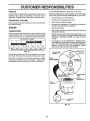
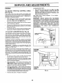
TO SHARPEN BLADE (See Fig. 14)
Always observe safety rules when performing any maintenance,
Care should be taken to keep the blade balanced° An
unbatanced blade willcause excessive vibration and eventual damage to mower and engine.
BRAKE OPERATION
•
The blade can be sharpened with a file or on a grinding
wheel. Do not attempt to sharpen while on the mower.
°
To check blade balance, you will need a 5/8" diameter
steel bolt, pin, or a cone balancer. (When using a cone
balancer, follow the instructions supplied With bal-
tf tractor' requires more than six (6) feet stopping distance
at high speed in highest gear, then brake must be adjusted°
(See "TO ADJUST BRAKE" in the Service and Adjustments section of this manual).
ancer_.
TIRES
•
•
Maintainproper air pressure in all tires (See "PROD*
UCT SPECIFICATIONS
on page 3 of this manual).
•
Keep tires free of gasoline, oil, or insect control chemicals which can harm rubber.
•
Avoid stumps, stones, deep ruts, sharp objects and
other hazards that may cause tire damage.
Slide blade on to an unthreaded portion of the steel bolt
or pin and hold the bolt or pin parallel with the ground,
If blade is balanced, it should remain in a horizontal
position_ If either end of the blade moves downward,
sharpen the heavy end until the blade is balanced..
NOTE: Do not use a nail for balancing blade. The lobes of
the center hole may appear to be centered, but are noL
NOTE: To seal tire punctures and prevent flat tires due to
slow leaks, tire sealant may be purchased from your local
parts dealer, Tire sealant also prevents tire dry rot and
corrosion_
CENTER
BLA£_E CARE
REMOVAL
BLADE
518" BOLT
OR PIN
For best results mower blades must be kept sharp. Replace bent or damaged blades.
BLADE
HOLE
(See Fig. 13)
.
Raise mower to highest position to allow access to
blades_
•
Remove hex bott, Iockwasher and flat washer securing
blade_
•
Install new or resharpened blade with trailing edge up
towards deck as shown.
•
Reassemble hex bolt, lock washer and flat washer in
exact order as shown°
FIG. 14
BATTERY
Your tractor has a battery charging system which is sufficient for normal use° However, periodic charging of the
battery with an automotive charger wiil extend its life.
•
Keep battery and terminals clean,
•
Tighten bolt securely (30-35 Ft. Lbs. torque).
IMPORTANT: BLADE BOLT tS GRADE 8 HEATTREATED.
•
Keep battery bolts tight.
•
Keep small vent holes open.
NOTE: We do not recommend sharpening blade- but if you
do, be sure the blade is balanced.
,
Recharge at 6-10 amperes for' 1 hour.
TO CLEAN BATTERY AND TERMINALS
Corrosion and dirt on the battery and terminals can cause
the battery to "leak" power.
•
Open battery box door..
•
Disconnect BLACK battery cable first then RED battery cable and remove battery from tractor°
•
Rinse the battery with plain water and dry.
•
Clean terminals and battery cable ends withwire brush
until bright°
•
Coat terminals with grease or petroleum jelly.
•
Reinstall battery (See "CONNECT
Assembly section of this manual).
EDGE
'
*A GRADE 8 HEAt" TREATED BOLT CAN EE
IDENTIFIED BY SIX LINES ON THE BOLT HEAD,
FIG. 13
16
BATTERY" in the
i
i
....................................................
CUSTOMER
ii
ii
i iiiiiii iiiiiiii
ii
,r,,-_ -
...........
,
ii
iiiiiiiii1,11111
RESPONSIBILITIES
i
i
iii
ii
ii
i
V-BELTS
TO CHANGE ENGINE OIL (See Figs. 15 and 16)
Check V_beits for deterioration and wear after 100 hours of
operation arid replace if necessary. The baits are not
adjustable. Replace belts if they begin to slip from wear.
Determine temperature range expected before oi! change.
All oil must meet API service classification SF, SG or SH,
°
Be sure tractor is on (eve( surface.
TRANSAXLE
•
°
Oi! will drain more freely when warm.
Catch oi! in a suitable container.
°
Remove oil fill cap/dipstick. Be careful not to allow dirt
to enter' the engine when changing oil
COOLING
Keep transaxle free from build-up of dirt and chaff which
can restrict cooling,
ENGINE
•
Remove drain plug.
LUBRICATION
•
After oil has drained completely, replace oil drain ptug
and tighten securely,
Only use high quality detergent oil rated with API service
classification SF, SG, orSH Select the oil's SAE viscosity
grade according to your expected operating tempe[ature.
•
Refill engine with oil through oil fill dipstick tube. Pour
slowly. Do not overfill. For approximate capacity see
"PRODUCT SPECIFICATIONS"
on page 3 of this
manual.
=
Use gauge on oil fill cap/dipstick for checking level.
Insert dipstick into the tube and rest the oil fill cap on the
tube. Do not thread the cap onto the tube when taking
reading. Keep oil at FULL line on dipstick° Tighten
cap onto the tube securely when finished.
SAE VISCOSITY GRADES
!
._
' .2o°
0.
°c-=o° . 'oo
_o, 3_o 40. .........
60°
G°
TEMP ERATUR E RANGE ANTIC|PATED
1o,
S0 •
_oo°
•
40"
B EFORE N EXT O(L CHANGE
FIG, 15
COVER KNOB
AIR CLEANER
COVER
Change the oil after every 50 hours of operation or at least
once a year if the tractor isnot used for 50 hours in one year.
,WING NUT
FOAM
PRE-CLEANER
Check the crankcase oil level before starting the engine
and after each eight (8) hours of operation. Tighten oil fill
cap/dipstick securely each time you check the oil level.
PAPER CARTRIDGE
AIR CLEANER
BASE
FILL
CAP'DIPST1CK
AIR
SCREEN
OIL DRAIN
PLUG
FIG_ 16
17
,i,im,i .....
i1,1
ii1,,,,,1111,,11111,11 ,lll,,,,,ll,
CUSTOMER
i
,
iillllllll
,i iii
i,,_1, i
i,,
i, ,,, i1,,,
RESPONSIBILITIES
ii
,
..............................
ill
i
i
ii ii
ill
CLEAN AIR SCREEN (See Fig. 16)
CLEAN AIR INTAKE/COOLING
Air screen rnust be kept free of dirt and chaff to prevent
engine damage from overheating. Clean with a wire brush
or compressed air to remove dirt and stubborn dried gum
fibers,
To insure proper cooling, make sure the grass screen,
cooling fins, and other external surfaces of the engine are
kept clean at all times°
AIR FILTER
Every 100 hours of operation (more often under extremely
dusty, dirty conditions), remove the blower housing and
other cooling shrouds. Clean the cooling fins and external
surfaces as necessary. Make sure the cooling shrouds are
reinstalled.
(See Fig. 16)
Your engine will not run properly using a dirty air filter_
Clean the foam pro-cleaner after every 25 hours of operation or every season. Service paper cartridge every 100
hours of operation or every season, whichever occurs first.
NOTE; Operating the engine with a blocked grass screen,
dirty or' plugged cooling fins, and/or cooling shrouds removed will cause engine damage due to overheating°
Service air cleaner more often under dusty conditions_
•
Remove knob and cover'.
MUFFLER
•
Remove wing nut and air cleaner from base.
TO SERVICE PRE-CLEANER
•
Slide foam pro-cleaner off cartridge.,
•
Wash it in liquid detergent and water.
•
Squeeze it dry in a clean cloth. Allow it to dry.
Inspect and replace corroded muffler and spark arrester (if
equipped) as it could create a fire hazard arid/or damage.
SPARK
Saturate it in engine oil. Wrap it in clean, absorbent
cloth and squeeze to remove excess oil.
TO SERVICE CARTRIDGE
Rdplace a dirty, bent, or damaged cartridge.
NOTE: Do not wash the paper cartridge or use pressurized
air', as this will damage the cartridge.
•
Reinstall the pre-cleaner (cleaned and oiled) over the
paper cartridge.
•
Reassemble air cleaner, wing nut, cover and tighten
knob securely.
PLUGS
Replace spark plugs at the beginning of each mowing
season or after every 100 hours of operation, whichever
occurs first. Spark plug type and gap setting are shown in
"PRODUCT SPECIFICATIONS" on page 3 of this manual.
•
•
AREAS
18
ENGINE OIL FILTER (See Fig. 17)
IN-LINE FUEL FILTER (See Fig. 18)
Replace the engine oil filter every season or every other oil
change if the tractor is used more than 100 hours in one
year.
The fuel filter should be replaced once each season. If fuel
filter becomes clogged, obstructing fuet flow to carburetor,
replacement is required.
•
Drain oil from engine crankcase (See "TO CHANGE
ENGINE OIL in this section of this manual, through
step remove drain plug).
Remove oil filter and wipe off filter' adapter_
•
With engine cool, remove filter and plug fuel line
sections.
•
Place new fuel filter in position in fuel line with arrow
pointing towards carburetor.
.
Apply a thin coating of new engine oil to the rubber
gasket on replacement oil filter.
,
Be sure there are no fuel line leaks and clamps are
properly positioned.
•
Install replacement oil filter on filter adapter'. Turn oil
filter clockwise until rubber gasket contacts the filter
adapter', then tighten _ter an additional 1/2 turn.,
•
Immediately wipe up any spilled gasoline.
•
Fill crankcase with new oil (See "TO CHANGE ENGINE OIL" in this section of this manual). For approximate capacity see "PROD UCT SPECIFICATIONS" on
page 3 of this manual.
.
Start the engine and check for oit leaks, Correct any
leaks before placing engine into full operation.
•
CLAMP
FUEL
FILTER
FIG. 18
CLEANING
°
Clean engine, battery, seat, finish, etco of al! foreign
matter°
•
Keep finished surfaces and wheels free of all gasoline,
oil, etc,
•
Protect painted Surfaces with automotive type wax.
We do not recommend using a garden hose to clean your
tractor unless the electrical system, muffler, air filter and
carburetor are covered to keep water outo Water in engine
can result in a shortened engine life.
FIG. 17
1.9
ii
, ,11
....
ii
,,
U l,lll
,
,i,,i, iir
ii
IIIIIINIu,
, u
iii
,UUl
,
i
, i lll, i
SERVICE AND ADJUSTMENTS
.................
i ..............
CAUTION:
•o
°
•
•
°
, .........................
,
.__
BEFORE PERFORMING ANY SERVICE OR ADJUSTMENTS:
Place gearshift
lever in
neutral
position.
Depress
clutch/brake
pedal
fully(N)and
set parking brake.
Place attachment clutch in "DISENGAGED"
position.
Turn ignition key "OFF" and remove key,
Make sure the blades and all moving parts have completely stopped.
Disconnect spark plug wire from spark plug and place wire where it cannot come in contact with
plug.
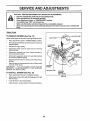
TRACTOR
TO REMOVE
MOWER
(See Fig. 19)
LEVER
Mower wiil be easier to remove from the right side of tracton
•
Place attachment clutch in "DISENGAGED"
position.
=
Move attachment lift lever forward to lower mower to its
lowest position.
•
Roll belt off engine pulley.
•
Disconnect clutch rod from clutch lever by removing
retainer spring.
°
Disconnect anti-sway bar' from chassis bracket by
removing retainer spring..
•
Disconnect suspension arms from rear deck brackets
by removing retainer springs.
°
Disconnect front links from deck by removing retainer
springs,
SUSPENSION
,
Raise lift lever' to raise suspension arms Slide mower'
out from under tractor.
IMPORTANT:
IF AN ATTACHMENT oTHER THAN THE
MOWER IS TO BE MOUNTED TO THE TRACTOR,
REMOVE THE FRONT LtNKS.
TO INSTALL
MOWER
RETAINER
)PRING
_NTI-SWAY BAR
SPRINGS
(BOTH SLOES)
(See Fig. 19)
•
Raise attachment lift lever to its.highest position,
•
Slide mower undertractorwith
side of tractor'.
•
•
Lower lift lever to its lowest position.
lnstatl mower in reverse order of removalinstructions.
FIG, 19
discharge guard to right
2O
.......................
,......
r., H
ii i
ii1,1
ii i,illl¸
iiilll,,i,ii
r
- u ....................
SERVICE AND ADJUSTMENTS
illll
ill
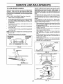
TO LEVEL
MOWER
ii i i ill
i.....................................................
i
HOUSING
FRONT-TO-BACK
Adjust the mower while tractor is parked on level ground or
Raise mower to its highest position,
At the midpoint of both sides of mower, measure height
from bottom edge of mower to ground. Distance"A" on
both sides of mower should be the same or within 1/4"
of each other,
•
If adjustment is necessary, make adjustment on one
side of mower only.
To raise one side of mower, tighten lift link adjustment
nut on that side.
•
°
To lower one side of rnower, loosen lift link adjustment
nut on that side.
NOTE:
Each full turn of adjustment nut will change mower
Recheck measurements
after adjusting.
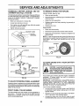
BOTTOM EDGE
To lower front of mower loosen nut "E" on both front
links an equal number of turns.
=
When distance "D" is 1/8" to 1/2" lower at front than
rear, tighten nuts "F" against trunnion on both front
links.
•
To raise front of mower, loosen nut"F" from trunnion on
both front links. Tighten nut "E" on both front links an
equal number' of turns.
When distance "D" is 1/8" to 1/2" lower at front than
rear, tighten nut"F" against tr unnion on both front links_
Recheckside-to-side adjustment.
BOTTOM EDGE
OFMOWERTO
GROUND
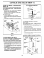
(See Figs. 22 and 23)
•
height about 1/8".
.
ADJUSTMENT
IMPORTANT: DECK MUST BE LEVEL SIDE-TO-SIDE. IF
THE FOLLOWING FRONT.TO-SACK ADJUSTMENT fS
NECESSARY, BE SURE TO ADJUST BOTH FRONT LINKS
EQUALLY SO MOWER WILL STAY LEVEL SIDE-TOSIDE.
To obtain the best cutting results, the mower' housing
should be adjusted so that the front is approximately 1/8" to
1/2" lower than the rear when the mower is in its highest
position.
Check adjustment on right side of tractor. Measure distance"D" directly in front and behind the mandrel at bottom
edge of mower housing as shown.
•
Before making any necessary adjustments, checkthat
both front links are equal in length. Both links should
be approximately 10-3/8".
,
If links are not equal in length, adjust one link to same
length as other link.
driveway.
Make sure tires are properly inflated (See
"PRODUCTSPECIFICATtONS"onpage3ofthismanual).
If tires are over or underinflated, you wiEInot properly adjust
your mower.
SiDE-TO-SIDE ADJUSTMENT (See Figs. 20 and 21)
•
•
...................
OFMOWERTO
GROUND
°
•
MANDREL
GROUNDLINE
FIG. 20
SUSPENSION
ARM
FIG. 22
BOTHFRONTLINKSMUSTBEEQUALIN LENGTH
LIFT LINK
ADJUSTMENT
NUT
FIG. 21
:
NUT "E"
NUT "F"
FRONT LINKS
21
TRUNNION
FIG. 23
RVICE AN
TO REPLACE
MOWER
BLADE
DRIVE
ADJUSTMENTS
BELT
WITHPARKING BRAKE "ENGAGED"
(See Fig. 24)
The mower blade drive belt may be replaced without tools°
Park the tractor on level surface, Engage parking brake,
BELT REMOVAL •
Remove mower from tractor (See %0
MOWER" in this section of this manual).
REMOVE
°
Work belt off both mandrel pulleys and idler pulleys.
•
Purl belt away from mower°
BELT INSTALLATION •
Install new belt in reverse order of removal.
•
•
Make sure bett is in all pulley grooves and inside all belt
guides_
Install mowerin reverse order of removal instructions.
FIG, 25
MANDREL
PULLEY
IDLER
PULLEYS
TO REPLACE
(See Fig, 26)
MOTION
DRIVE
BELT
Park the tractor on level surface. Engage parking brake_
For assistance, there is a belt installation guide decal on
bottom side of left footrest.
=
Remove mower (See "TO REMOVE MOWER" in this
section of this manual,,)
•
•
Remove upper belt keeper.
Remove belt from stationary idler and clutching idler.
•
Pull belt slack toward rear of tractor. Remove belt
upwards from transaxle pulley by deflecting belt keepers.
Pull belt toward front of tractor and remove downwards
from around engine pulley.
•
MANDREL
PULLEY
•
Install new belt by reversing above p_ocedure.
IMPORTANT: MAKE SURE UPPER BELT KEEPER IS
POSITIONED PROPERLY BETWEEN LOCATOR TABS,
FIG. 24
TO ADJUST
BRAKE
ENGINE',.-,-.
PULLEY
(See Fig, 25)
Your' tractor is equipped with an adjustable brake system
which is mounted on the right side of the transaxle_
CLUTCHING'--..=
IDLER
__.LLoJ_
J
If tractor requires mere than six (6) feet stopping distance
at high speed in highest gear', then brake must be adjusted.
•
Depress clutch/brake pedal and engage parking brake,
•
Measure distance between brake operating arm and
nut "A" on brake rod.
•
If distance is other than 1-1/2", loosen jam nut and turn
nut "A" until distance becomes 1-1/2". Retighten jam
nut against nut "A".
•
_LOCATOR
TABS
UPPER EELT
KEEPER
STATIONARY _'_
IDLER
|
PULLEY
Road test tractor for pr'oper stopping distance as stated
above° Readj.ust if necessary. If stopping distance is
still greater' than six (6) feet in highest gear, further
maintenance is necessary. Contact your nearest au_
thorized service center/departmento
FIG. 26
22
,,
iiii
HIH
................
,,,,,"
,
-
.................
I
I
I'
SERVICE AND ADJUSTMENTS
. •
TRANSAXLE
SHIFTER
LINKAGE
JUSTMENT
(See Figs. 27 and 28)
AND
AD-
ii ,,
TO REMOVE
ii,
J HHll I
' '1'
HH
JI,
,
WHEEL FOR REPAIRS
FRONT WHEEL (See Fig. 29) -
The transaxle should be in neutral when the gearshift lever
is in the neutral (N) (lock gate) position, The adjustment is
preset at the factory; however, if adjustment is needed,
proceed as fol!ows:
•
•
Make sure transaxte is in neutral (N).
Loosen two Iocknuts on tie rod.
•
Turn center rod until gearshift lever falls into neutral
lock gate on fender console_
•
Tighten Iocknuts securely.
•
Block up axle secureiy.
•
Remove axle cover, retaining ring and washers to a_low
wheel ternovalo
•
Repair tire and reassemble_
°
Replace washers and snap retaining ring securely in
axle groove.
•
Replace axle cover.
REAR WHEEL °
Block rear axle securely.
°
Remove five (5) hub bolts to allow wheel removal
•
Repair tire and reassemble°
botts securely.
LOCKGA_E
Reptace and tighten hub
NOTE: To seal tire punctures and prevent flat tires due to
slow leaks, tire sealant may be purchased from your' local
parts dealer_ Tire sealant also prevents tire dry rot and
corrosion.
WASHERS
FiG. 27
RETAINING
RING
AXLE
COVF-R
ROD
FIG. 29
\
TO START ENGINE WITH A WEAK BATTERY
See Fig. 30)
, i,
,_,
_[_
TRANSAXLE
iii
STEERING
WHEEL
WHEEL
H,H,
i
CAUTION: Lead-acid batteries generate explosive gases. Keep sparks, flame
and smoking materials away from batteries. Always wear eye protection
when around batteries,
,
iiiiii
,11111
iiii
i
i
|
i
I
i i iilll:
IMPORTANT:
YOUR TRACTOR
IS EQUIPPED
WITH A
t2 VOLT NEGATIVE GROUNDED
SYSTEM, THE OTHER
VEHICLE
MUST ALSO BE A 12 VOLT
NEGATIVE
GROUNDED
SYSTEM,
DO NOT USE .YOUR TRACTOR
BATTERY TO START OTHER VEHICLES.
ALIGNMENT
,If.steering wheel crossbars are not hot_zonta! (left to right)
when wheels are positioned straight forward, remove steering wheel and reassemble per instructions in the Assembly
section of this manual
FRONT
i,,
If your battery is too weak to start the engine, it should be
recharged,
If "jumper cables" are used for emergency
starting, follow this p_ocedure:
FIG. 28
TO ADJUST
i
HI
TO ATTACH JUMPER CABLES °
Connect each end of the RED cable to the POSITIVE
(+) terminal of each battery, taking care not to short
against chassis.
°
Connect one end of the BLACK cable to the NEGATIVE (-) terminal of fully charged battery.
°
Connect the other end of the BLACK cable to good
CHASSIS GROUND, away from fuel tank and battery.
TOE-IN/CAMBER
The front wheel toe-in and camber are not adjustable on
your tractor_ If damage has occurred to affect the front
wheel toe-in or camber, contact your nearest authorized
service centeddepartrnent.
23
.,;
....
,,, ..................
ii ..................
,,
........................
SERVICE AND ADJUSTMENTS
iiim
i
iii,
-ii
............................
, ....................
iiii I,
ii
i
ii
iii
i.'*t_ "_-_'_*_
TO REMOVE CABLES, REVERSE ORDER -
TO REPLACE
•
Replace with 30 amp automotive-type plug-in fuse.
fuse holder is located behind the dash.
•
BLACK cable first from chassis and then from the fully
charged battery,
RED cable last from both batteries.
POSITIVETERMINAL
FUSE
The
TO REMOVE HOOD AND GRILL ASSEMBLY
(See Fig. 31)
NEGATIVETERMINAL
.
Raise hoed°
°
Unsnap headlight wire connector.
•
Stand in front of tractor. Grasp hood at sides, tilt toward
engine and lift off of tractor.
•
To replace, reverse above procedures.
J
\
_
HOOD
_
HEADLIGHT
_
WiRE
CHARGED
j_y
POSITIVE
NEGATIVE
TERMINAL
FiG. 30
TO REPLACE
HEADLIGHT
BULB
°
Raise hood.
,
Pull bulb holder' out of the hote in the backside of the
grill.
•
Replace bulb in holder and push bulb holder securely
back into the hole in the backside of the grill.
Close hood°
•
INTERLOCKS
FIG, 31
AND RELAYS
Loose or damaged wiring may cause your tractor to run
poorly, stop running, or prevent it from starting.
•
Check wiring. See electrical wiring diagram in the
Repair Parts section of this manual.
24
cO..ECTOR
......
_
......
_,.,.,
i.i
, •
nnll
ii iii
nm
ii iiii
AND ADJUSTMENTS
iiii
,lllllllllllllll
i ii
n,
ACCELERATION
ENGINE
•
TO ADJUST THROTTLE
(See Fig. 32)
CONTROL
•
With engine not running, move throttle control lever
from slow (,,_a_,)to choke (N) position. Slowly move
lever from choke (N) to fast (,¢i_) position.
•
Check to see if hote in throttle lever and hole in speed
control bracket are aligned.
•
If holes are not aligned loosen cable clamp screw and
align the holes by inserting a pencil or a t/4" drill b t
through both holes.
•
Putl throttle cable up to remove slack and tighten cable
clamp screw. Remove aIignment pencil or drill bit.
TO ADJUST
CARBURETOR
-
Move throttle control lever' from slow (,_)
to fast
position°
If engine hesitates or dies, tum idle
adjusting needle out (counterclockwise)
1/8 turn.
pea! test and continue to adjust, if necessary,
eng;ne accelerates
smoothly.
CABLE
The throttle control has been preset at the factory and
adjustment should not be necessary_ Check adjustment as
described below before loosening cableo If adjustment is
necessary, proceed as follows:
TEST
in in
High speed stop is factory
damage may resutt.
adjusted.
CABLE
CLAMP
SCREW
(See Fig. 33)
SPEED CO_
BRACKET
In general, turning the adjusting needles in (clockwise)
decreases the supply of fuel to the engine giving a leaner
fuel/air mixtu re. Turning the adjusting needles out (counterclockwise) increases the supply of fuel to the engine giving
a richer fuel/air mixture
THROTTLE
LEVER
IMPORTANT:
DAMAGE TO THE NEEDLES AND THE
SEATS IN CARBURETOR MAY RESULT IF NEEDLE IS
TURNED IN TOO TIGHT.
FIG. 32
m
NOTE: The carburetor on this engine is low emission. It is
equipped with an idle fuel adjusting needle with a limiter
cap, which allows some adjustment within the limits allowed
by the cap. Do not attempt to remove the limiter cap. The
limitercap cannot be removed without breaking the adjusting
needle.
Be sure you have a clean air filter and the throttle
control cable is adjusted properly (see above).
•
Start engine and allow to warm for five minutes. Make
adjustmentswith engine running and shift/motion controt
lever in neutral (N) position.
•
Idle speed se!ting - With throttle control lever in slow
(,_) position, engine should idle at 1750 RPM. If
engine idles too slow or fast, turn idle speed adjusting
screw in or out until correct idle is attained.
•
Idle fuet needle setting - With throttle control lever in
slow (,,a_) position, turn idte fuel adjustment needle in
(clockwise) until engine begins to die and then turn out
(counterclockwise) until engine runs rough. Turn needle
to a point midway between those two position&
•
Do not adjust
-
IMPORTANT;
NEVER TAMPER
WITH THE ENGINE
GOVERNOR,
WHICH IS FACTORY
SET FOR PROPER
ENGINE SPEED. OVERSPEED1NG
THE ENGINE ABOVE
THE
FACTORY
HIGH
SPEED
SETTING
CAN BE
DANGEROUS
IF YOU THINKTHE
ENGINE-GOVERNED
HIGH SPEED NEEDS ADJUSTING,
CONTACT
YOUR
NEAREST
AUTHORIZED
SERVICE
CENTER/
DEPARTMENT,
WHICH HAS PROPER EQUIPMENT
AND
EXPERIENCE
TO
MAKE
ANY
NECESSARY
ADJUSTMENTS.
Tile carburetor has been preset at the factory and adjustment should not be necessary. However', minor adjustment may be required to compensate for differences infuel,
temperature, altitude or load. If the carburetor does need
adjustment, proceed as follows:
•
(,_)
fuel
Reuntil
IDLE SPEED
ADJUSTING
I ADJUSTING
CNEEDLE
FIG, 33
Recheck idle speed° Readjust if necessary,
25
,,
................
_
,,,_
lUl"llTi
,i
,.,
iiiii1,11
¸
ul
....
;'--_!__*-="--_A_
.....
STORAGE
ENGINE
Immediately prepare your tractor for storage at the end of
the season or if the tractor will not be used for 30 days or
more.
II
'1
_, _
_
illul
....................
ii
FUEL SYSTEM
ii1,1,,i
gasoline in the tank inside a building
where fumes may reach an open flame
or
spark. Never
Allow store
the engine
to cool
CAUTION:
the tractor
with
before storing in any enclosure.
IMPORTANT: tT IS IMPORTANT TO PREVENT GUM
DEPOSITS FROM FORMING IN ESSENTIAL FUEL
SYSTEM PARTS SUCH AS CARBURETOR, FUEL FILTER,
FUEL HOSE, OR TANK DURING STORAGE.
ALSO,
EXPERIENCE INDICATES THAT ALCOHOL BLENDED
FUELS (CALLED GASOHOL OR USING ETHANOL OR
METHANOL) CAN ATTRACT MOISTURE WHICH LEADS
TO SEPARATION AND FORMATION OF ACIDS DURING
STORAGE.
ACIDIC GAS CAN DAMAGE THE FUEL
SYSTEM OF AN ENGINE WHILE 1N STORAGE.
i
|
|!
TRACTOR
Remove mower from tractor for winter storage. When
mower is to be stored for a period of time, clean it thorOugllty, remove all d{rt, grease, leaves, etc. Store in a
clean, dry area.
•
Clean entire tractor (See"CLEANING" in the Customer
Responsibilities section of this manual).
•
Inspect and replace belts, if necessary (See belt re placement instructions in the Service and Adjustments
section of this manual).
•
•
After a period of time in storage, battery may require
recharging.
•
•
Start the engine and let it run until the fuel lines and
carburetor are empty.
•
Never'use engine or carburetor cleaner products in the
fuel tank or permanent damage may occur°
Use fresh fuel next season.
ENGINE OIL
Drain oil (with engine warm) and repiace with clean engine
oil
(See "ENGINE" in the Customer Responsibilities
section of this manual).
BATTERY
-
•
NOTE: Fuel stabilizer is an acceptable alternative in
minimizing the formation of fuel gum deposits during storage. Add stabilizer to gasoline in fuel tank or storage
container_ Always follow the mix ratio found on stabilizer
container, Run engine at least t0 minutes after adding
stabilizer to atlow the stabilizer to reach the carburetor. Do
not drain the gas tank and carburetor if using fuel stabilizer.
Touch up all rusted or chipped paint surfaces; sand
lightly before painting.
Fully charge the battery for storage.
Drain the fuettank,
•
Lubricate as shown in the Customer Responsibilities
_ction of this manual
Be sure that all nuts, bolts and screws are securely
fastened, inspect moving parts for damage, breakage
and wear° Replace if necessary.
•
•
CYUNDERS
To help prevent corrosion and power leakage during
tong periods of storage, battery cables should be
disconnected and batterycleaned thoroughly (see"TO
CLEAN BATTERY AND TERMINALS in the Customer' Responsibilities section of this manual)_
After cleaning, leave cables disconnected and place
cables where they cannot come in contact with battery
terminals.
•
Remove spark ptug(s).
•
Pour one ounce of oil through spark plug hole(s) into
cylinder(s).
=
Turn ignitionkey to"START" position for a few seconds
to distribute oil
,
Replace with new spark plug(s).
OTHER
•
Be sure battery drain tube is securely attached.
•
Do not store gasoline from one season to another.
•
If battery is removed from tractor for storage, do not
store battery directly on concrete or damp surfaces.
•
Replace your gasoline can if your can starts to rust°
Rust and/or dirt in your gasoline will cause problems.
•
If possible, store your tractor indoors and cover it to
give protection from dust and dirt.
o
Cover your tractor with a suitable protective cover that
does not retain moisture_ Do not =useplastic. Plastic
cannot breathe which allows condensation to form and
will cause your tractor' to rusL
IMPORTANT: NEVER COVER TRACTOR WHILE ENGINE
AND EXHAUST AREAS ARE STILL WARM
26
PROBLEM
CAUSE
Will not start
1,
Out of fuel
2,
3,
4
5,,
6
7,
Engine not "CHOKED"
Engine flooded,
Bad spark plug
Dirty air fitte_
Dirty fuel filter
Water in fuel
8
9
Loose or damaged wiring
Carburetor out of adjustment,
10
ii
i i
CORRECTION
............
m,
1,
Fill fuel tank.
2.
3,
4,
5,
6.
7,
See "TO START ENGINE" in Operation section,,
Wait several minutes before attempting to start
Replace spark ptugo
Clean/replace air filter,
Replace fuel filler.
Drain fuel tank and carburetor, refill lank with fresh
gasoline and replace fuel filler
Check all wiring.
See "To Adjust Carburetor" in Service Adjustments
section.
8.
9
Engine valves out of adjustment
, ,,,,,,,,,,,,,,,,,,,
Hard to start
properly.
10,,
Nm
,
Contact an authorized service center/department,
iiiiiiir
1
2,
3
4,
5.
6
7,
Di_-ty air filter
Bad spark plug
Weak or dead battery,
Dirty fuel filler,,
Stale or dirty fuel
Loose or damaged widng
Carburetor out of adjustment,
1,
2,
3
4.
5,
6.
7
Clean/replace air filter,
Replace spark plug
Recharge or replace battery
Replace fuel rifler
Drain fuel tank and refiti with fresh gasoline
Check all wiring.
See "To Adjust Carburetor" in Service Adjustments
section.
8
Engine valves out of adjustment,
8,
Contact an authorized
I,
2
3
4
Clutch/brake pedal not depressed,
Attachment clutch is engaged,,
Weak or dead battery
8town fuse
5
6,
7
8
9
Corroded battery terminals
Loose or damaged wiring
Fautty ignition switch,
Faulty solenoid otstarter
Faulty operator presence switch(as)
1
2.
3,
4
5.
6
7,
8,
9
Depress crutch/brake pedal,
Disengage attachment clutch,
Recharge or replace battery,
Replace fuse
Clean battery terminals,
Check all widng.
Check/replace ignition switch
Check/replace solenoid or starter,
Contacl an authorized service center/department
Engine cticks but witl not
start
1
2,
3
4,
Weak or dead battery,.
Corroded battery terminals
Loose or damaged wiring,
Faulty solenoid or starter
1,
2,
3.
4,
Recharge or replace battery,
Clean battery terminals,
Check all wiring
Check/replace solenoid or starter,
Lose of power
1
2.
3.
4
5
6,
7_
8,,
9
Cutting too much grass/too fast
Throttle tn "CHOKE" position.
Build-up of grass, leaves and trash under mower
Dirty air filter:
Low Oil leveVdirty oil
Faulty spark plug
Dirty fuel filter,
Stale ordirty fuel
Water in fuel,
1,
2,
Set in"Higher Cut" poe!lion/reduce
Adjust throttle control
3,
4
5
6
7,
8,
9,
Clean underside of mower housing.
Clean/replace air filter
Check oIlleveVehange oil
Clean and regap or change spark plug.
Replace fuel filter.
Drain fuel tank and refill with fresh gasoline,
Drain fuel tank and carburetor, refill tank with fresh
gasoline and replace fuel filter,
Connect an d tighten spark P!ug wire. _ _
Clean engine air screen/fins,
Clean!replace muffler,
Check all wiring.
See "To Adjust Carburetor" th Service Adjustmenis
section.
Contact an authorized service center/departmento
service center/department,
=1,
Engine will not turn over
•
iql[
nl
iii
ii
10
11
12
13
!4
Spark plug wire loose
Dirty engine air scree n/fins
Dirty/clogged muffler.
Loose or damaged wiring
Carburetor out of adjustment,
I0,
11,
12,
13
14
15
Engine valves out of adluslment
15,
III'IU
Excessive
vibration
1_
2
3
inl
nl'l
"n'u
Worn, bent or loose blade.
Bent blade mandrel,
Loose/damaged part(s),
t
2.,
3.
27
i
inl
speed.
u ii
Replace blade, Tighten blade bolt,
Replace blade mandrel.
Tighten loose part(s). Replace damaged parts,
,
ii
ii ,44
iiii
14,¸,,= ,i
,,_,:,
.....
TROUBLESHOOTING
PROBLEM
CAUSE
Engine continues to run
when operator leaves seat
with attachment ciutch
1.
'................
_
•
_:,
_:_
_-,,i
POINTS
CORRECTION
Faultyoperator-safe_presen_controlsystem.
1,
Check wtdng, switches and connections. If not
corrected, contact an authorized service center/
department,
engaged
, .........
Poor cut = uneven
................
,,
='4
I=
...............
--
1.
2,
Worn, bent or loose blade_
Mower deck not le(,el
1,
2o
Replace blade. Tighten blade boil
Level mower deck,
3,
4
5
Buildup of grass/leaves= and trash under mower.
Bent blade mandrel
Clogged mower deck vent holes from buildup of
grass, leaves, and trash around mandrels,,
3
4,
5.
Clean underside of mower housing.
Replace blade mandrel
Clean around mandrels to open vent holes.
i,,i,
Mower blades will not
rotate
Poor grass discharge
1,
Obstruction
1,
Remove obstruction
2.
3_
4o
Worn!damaged mower ddve belt
Frozen idler pulley,
Frozen blade mandrel
in clutch mechanism
2.
3
4,
Replace mower ddve bell
Replace idler pulley°
Replace blade mandrel.
1.
2,
3_
4,
Engine speed too slow.
Travel speed too fast,.
Wet grass,,
Mower deck not level
1.
2,
3,
4,
Place throttle conlrol in"FAST" position.
Shift to slower speed.
Allow grass to dry before mowing
Level mower deck
5
6_
7_
8,
Low/uneven tire atr pressure
Worn, bent or loose blade
Buildup of grass, leaves and trash under mower
Mower ddve bait worn.
5.
6
7_
8,
9,
IO
11,
Check tires for proper air pressure,.
Replacetsharpen biade_ Tighten blade bolt.
Clean underside of mower housing
Replace mower drive belt
Reinstall blades sharp edge down°
Replace with blades listed in this manual,
Clean around mandrels to open vent holes.
19"0 Blades improperly Installed
improper blades used,
11. Clogged mower deck vent holes trom buildup of
grass, leaves, and trash around mandrels
-..,=
Headlight(s) not working
(if so equipped)
,11 U,lllH
1,.
Switch is "OFF".
1.
Turn switch"ON".
2,
3,
4
5
Bulb(s) burned out,.
Faulty light switch
Loose or damaged widng.
Blown fuse,
2.
3,
4
5.
Replace bulb(s).
ChecWreplace light switch.
Check widng and connections
Replace fuse..
1
2.
Bad battery cell(s)
Poor cable connecttonso
1,
2
Replace battery,
Cheek!clean atl connections.
3.
4.
Faulty regulator (if so equipped)
Faulty alternator.
3,
4
Replace reguIatoro
Replace alternator.
I.
Engine throttle control not set at =SLOW"
position for 30 seconds before stopping engine
1.
Move throttle control to "SLOW" position and allow
to idle for 30 seconds before stopping engine,,
,11
Battery will not charge
i
Engine "backfires"
when turning engine
"OFF"
'IN'H,'
III
28
TRACTOR
- - MODEL NUMBER
917,258543
SCHEMATIC
RED
BLAOK
BATTERY
1
RED
t
q
FUSE 3O AMP_
AMMETER
(OPTIONAL)
STARTER
BLACK
WHITE
I
I
SOLENOID
7
[
)G
.......
J
CLUTCH / BRAKE
(PEDAL UP)
L_
WHITE
2_Zc
SEAT SWITCH
(NOT OCCUPIED)
IGNITION
SWITCH
....
t....
t
r
1
I
t
I
l
--
8LACK
_A@-M_NTCL-UYCH_
[_
(CLUTCH _UT_ H _']
f
GROUNDING
CONNECTOR
METER
HOUR j_
IGNITION SWITCH
POSITION
CIRCUIT
"MAKE"
OFF
G + M +L
NoNE
RUN/UGHT
B + L
A + Y
RuN
__START
NO'rE
YOUR TRACTOR IS
EQUIPPED WITH A SPECIAL
ALTERNATOR SYSTEM.
THE LIGHTS ARE NOT
CONNECTED TO THE
BATTERY, BUT HAVE THEIR
OWN ELECTRICAL SOURCE.
BECAUSE OF THIS, THE
BRIGHTNESS OF THE LIGHTS
WILL CHANGE WITH ENGINE
SPEED. AT IDLE THE LIGHTS
WILL DIM. AS THE ENGINE IS
NON-REMOVABLE
SPEEDED UP, THE LIGHTS
CONNECTIONS
WTLL BECOME THEIR BRIGHTEST.
@
WIRING INSULATED
NONE
©
REMOVABLE
CONNECTIONS
CLIPS
IF WIRING INSULATED CLIPS
8+L ..........
NONE NOTE:
SERVICING OF UNIT, THEY SHOULD
IB+L+S
HEADLIGHTS
PROPERLY SECURE YOUR WIRING.
29
WERE REMOVED FOR
BE REPLACED TO
REPAIR PARTS
TRACTOR
- - MODEL NUMBER
917.258543
ELECTRICAL
t
i
I
\ I
1
26
I
19
20
25
45
I
,)/
_
_
"_'"
1
"-
3O
-
-
---.,
_ _
_
REPAIR PARTS
TRACTOR
- - MODEL NUMBER
917.258543
ELECTRICAL
KEY
NO.
PART
NO,
1
2
3
4
6
7
8
9
16
19
20
21
22
24
25
14614O
74760412
STD55t025
STD551125
STD541025
109238X
156417
109596X
153664
STD551125
73350400
147430
4152J
4799J
146147
26
28
29
30
31
32
33
40
4t
42
43
44
45
52
7O
108824X
4207J
121305X
1403O1
124211X
141226
109310X
156442
7111O4O8
131563
145673
73640400
121433X .
14194O
142621
NOTE:
DESCRIPTION
Battery,12 Vott 30 Amp
Bolt, Hex 1/4-20 x 3/4
Washer 9/32 x 5/8 x 16 Gauge
Washer, Lock 1/4
Nut, Hex 1/4-20
Tube, Plastic, 1/2"
Case, Battery Mech Hinge
Clamp, Hose
Switch, Interlock Push-tn
Washer, Lock 1/4
Nut, Hex, Jam 1/4-20 UNC
Harness, Light Socket (w/4152J)
Light Bulb
Cable, Battery, 6 Gauge, Red, 11"
Cable, Battery, 6 Gauge, Red, W16
Wire
Fuse,
Amp 6 Gauge, Black, 12"
Cable, 30
Ground,
Switch, Plunger
Switch, Ignition 4 Position
Nut, Ignition
Cover, Ignition Switch
Key, Molded, Craftsman
Harness, Ignition
Bolt Bik Fin Hex 1/4-20 UNC x t/2
Cover, Terminal
Solenoid
Nut,Keps BIk Hex 1/4-20 UNC
Ammeter, Rectangular 6 Amp
Protection Wire Loop (Hour' Meter)
Harness, Engine Kohl Cmd-L Dual
All component dimensions
1 inch = 25A mm
31
given in U.S. inches
REPAIR PARTS
TRACTOR
CHASSIS
- - MODEL NUMBER
917.258543
AND ENCLOSURES
28
J
12
58
53
31
/
37
54
60
14
3
38,
39
32
REPAIR PARTS
TRACTOR
CHASSIS
- - MODEL NUMBER
917.258543
AND ENCLOSURES
KEY
NO.
PART
NO.
1
2
3
4
5
9
10
11
12
13
14
17
18
25
26
28
29
30
31
37
38
39
51
52
53
54
55
57
58
60
64
71
74
140
142
143
144
145
147
o_-
159527
140356
1749O612
19131216
155272
150156X011
STD533710
155927
145660
155936
17490608
144983X558
t26938X
19131312
STD541437
145198X558
145200
151287X558
139976
17490508
139886
139887
73800400
19091416
145201
17030814
145202
STD552507
150127
72140606
154798 "
73680400
73680600
158418
156095
154966
154207
156524
74760412
5479J
NOTE:
DESCRIPTION
Chassis Assembly
Drawbar
Screw, Thd., Rol!. 3/8-16 x 3/4
Washer 13/32 x 3/4 x 16 Gauge
Bumper Hood/Dash
Dash
Bolt, Carriage 3/8-t6 x 3/4
Panel, Dash, LH
Clip Tinnerman Grille P/L
Panel, Dash, RH
Screw, Thdo, Roll. 3/8-16 x 1/2
Hood Assembly
Bumber Hood
Washer 13/32 x 13/16 x 12 Gauge
Locknut
Grille w/Clips MS-558
Lens, Grilte
Fender/Footrest Pnt STLT N Hold 558
Bracket, FenderJSupport
Screw Thdrol 5/16-18 x 1/2
Pivot Bracket Assembly, LH,
Pivot Bracket Assembly, RH,
Nut Lock w/Insert 1/4 - 20 UNC
Washer, 9/32 x 7/8 x 16 Gauge
Bracket, Grille Pickoff LH
Screw, Hex Head, Spiderlock #8 x 7/8
Bracket, Gdlle Pickoff RH
Bolt, FinHex 1/4 -20 UNC x .75
Duct, Air Engine PIJLT
Bolt, Rdhd Sqnk 3/8-16 UNC x 3/4
Dash, Lower STLT
Nut, Crownlock 1/4-20 UNC
Nut, Crownlock 3/8-16 UNC
Bracket, Suspension Front
Plate, Reinforcement STLT
Backrest, Swaybar Chassis
Bracket, Footrest STLT
Rod Pivot Chassis/Hood
Bolt Hex Hd 1/4-20 UNC x 3/4
Plug, Button
All component dimensions given in U.S. inches
1 inch = 25.4 mm
33
REPAIR PARTS
TRACTOR
- - MODEL NUMBER
917.258543
DRIVE
85
22
34
26 27
REPAIR PARTS
TRACTOR
- - MODEL NUMBER
917.258543
DRIVE
KEY'
NO,
1
2
3
4
5
6
8
10
11
t3
14
15
18
19
2t
22
24
25
26
27
28
29
30
31
32
34
35
36
37
38
39
40
41
42
47
48
49
50
51
52
PART
NO.
....
146682
t23666X
12000028
t21520X
17490512
t54792
STD561210
105701X
74550412
STD551125
74490544
STD523710
STD541437
106933X
130804
STD541237
106888X
STD55t037
STD561210
145204
124236X
130807
127275X
STD523107
155071
120183X
STD551062
STD571810
123674X
STD523727
4470J
154777
19131312
127783
154604
123205X
STD523715
STD541437
STD541431
DESCRIPTION
Transaxle(See Breakdown)
Peerless, Model Number 930-057A
Spring, Return, Brake
Pulley, Transaxle
Ring, Retainer
Strap, Torque
Screw, Thd+, Roll. 5/16-18 x3/4
Rod Shifter Fender STLT
Pin, Cotter
Washer', Shift Plate
Bolt 1/4+28 UNF W/Patch Grade 8
Washer
Bolt, Hex Flghd 5/16+18 Grade 5
Bolt Fin Hex 3/8-t6 UNC x t+ Gr5
Nut
Knob
Rod, Brake
Nut
Spring, Brake Rod
Washer
Pin
Rod, Parking Brake
Cap, Parking Brake, Red
Bracket, Transaxle
Keeper, Belt, L.H+
Bolt
Shaft Assembly, Foot Pedal
Bearing, Nylon
Washer
Roll Pin
Pulley, Idler', Flat
Bolt
Spacer', Split .395 x .59
Keeper, Belt, IdlerFooI-Proof
Washer t 3/32 x13/16 x12 Gauge
Pulley, Idler, V-Groove, Plastic
BellcrankAssembly
Retainer, Belt
Bolt
Nut Crown Lock 3/8-16 UNC
Nut Crown Lock 5/t6-t8 UNC
KEY
NO.
PART
NO.
53
55
56
57
58
59
61
62
63
64
105710X
105709X
STD523712
130801
127274X
140312
17490612
8883R
140186
71170764
65 STD551143
66 154778
70 134683
72 19132012
74 137057
75 121749X
76 STD581075
77 123583X
78 121748X
79 2228M
80 145090
81 156049
82 123782X
83 19171216
84 !45643
85 150360
86 71208
87 192120t6
88 12000008
89 154886
90 124346X
96 4497H
112 19091210
113 127285X
116 72110610
118 154774
121 154419
DESCRIPTION
Link, Clutch
Spring, Clutch Return
Bolt Fin Hex 3/8-16 x 1-1/4
V-Belt, Ground Drive
Keeper, Belt, R+H+
Keeper, Belt, Center Span
Screw, Thd+, Roll+ 3/8+16 x 3/4
Cover, Pedal
Pulley, Engine
Bolt, Hex Head, Fin.
7/16+20 x 4 Grade 5
Washer
Keeper, Belt, Engine, Fool-Proof
Guide, Mower Drive Belt, R.H.
Washer 13/32 x 1-1/4 x 12 Gauge
Spacer, Axle
Washer 25/32 x 1-1/4 x 16 Gauge
E-Ring
Key, Square 2.0 x.1845/.1865
Washer 25/32 x 1-5/8 x 16 Gauge
Key Woodruff #9 3/16 x 3/4
Arm, Shift
Shaft Assembly
Spring, Torsion
Washer 17/32 x 3/4 x 16 Gauge
Tie Rod
Nut, Nylock
• Bushing, Pivot
Washer
E-Ring
Console, Shift, STLT
Nut, Self-Threading, Washer Hd 1/4
Retainer Spring 1 Zinc Cad
Washer 9/32 x 3/4 x 10 Gauge
Strap Torque LT
Bolt Rdhd Sqneck 3/8+16 x 1.25
Spacer Bellcrank
Nytiner Clutching STL
NOTE: All component dimensions given in U.S. inches
1 inch = 25+4 mm
35
REPAIR PARTS
TRACTOR
STEERING
- - MODEL NUMBER 917.258543
ASSEMBLY
. ° °22_2:2£?-.
62
44
68
4O
36
70
_
REPAIR PARTS
TRACTOR
- - MODEL NUMBER 917.258543
STEERING ASSEMBLY
KEY
NO,
PART
NO.
1
2
3
4
5
6
7
8
9
10
tl
13
15
17
18
19
20
21
22
23
25
26
27
28
29
3O
32
36
37
38
39
4O
41
42
43
44
46
47
51
53
54
62
63
65
66
67
68
69
70
121472X
154427
156483
157473
6266H
12t748X
19272016
12000029
3366R
156438
STD551137
154779
73901000
156546
57079
124035X
t26684X
STD551125
71100410
1275O1
154406
126847X
136874
19131416
17490612
STD561210
130465
155099
152927
126805X
19133808
SDT54!537
100711L
145054
12t749X
153720
121232X
6855M
STD541431
73680600
74780520
156594
STD523710
154780
154404
74781044
154429
160367
74780636
DESCRIPTION
Wheel, Steering
Axle, Asm Front
Spindle, Asm Lh
Spindle, Asm Rh
Bearing, Race Thrust Harden
Washer, 25/32 x 1 5/8 x 16ga
Washer, 27/32 x 1 1/4 x t6 Ga
Ring, Klip #t5304-75
Bearing, Co! Strg B_k
Dragiink, Extended Stamped
Washer, Lock Hvy Htcl Spr 3/8
Bearing, Axle STLT/GT
Locknut, Flange 5/8-11 UNC
Shaft, Asm Strg Private Label
Washer', Thrust 515 x 750 x 033
Support, Shaft
Washer, Shim 1/4 x 5/8 x 062
Washer, Lock Hvy Helical 1/4
Screw,Hex Socket Hd 1/4-20 x 5/8
Shaft, Asm Pittman
Bracket, Steering
Bushing, Rod Tie Blk Lt
Gear', Sector
Washer', 13/32 x 7/8 x 16ga
Screw; Thdro1318-I6x3/4 Ty-tt
Pin, Cotter 1/8 x 3/4 Cad
Rod, Tie Wire Form 19 75 Mech
Bushing, Strg 5/8 Id Dash
Screw, TT #10-32 x 5 x 3/8 Flange
Inselt, Steedng Wheel
Washer, 13/32 x 2-3/8 x 8 Gauge
Gripco Nut
Adaptor, Wheel Strg
Boot Shaft Steering
Washer, 25/32 x 1-1/4 x 16 Gauge
Extension, Steering Non-Adjust
Cap, Spindle Fr Top Bik
Fitting, Grease
Nut Lock Hex w/Ins 5/16 q8 UNC
Nut, Crownleck 3/8-16 UNC
Bolt Fin Hex 5/16 -.18 UNC x I -1/4
Kit, Steering Assembly
Bolt, Fin Hex 3/8-16 UNC x 1 Gr. 5
Spacer, Axle
Bearing, Arm Pittman
Bolt, Fin Hex 5!8-11 UNC x 2-3/4
Axle, Brace
SpacerBrace Axle
Bolt Fin Hex 3/8-16 UNC x 2-1/4
NOTE: All component dimensions given in U.& inches
1 inch = 25.4 mm
37
REPAIR PARTS
TRACTOR
- - MODEL NUMBER
917.258543
SEAT ASSEMBLY
8
5
21
KEY
NO.
PART
NO.
1
2
3
4
5
6
7
8
9
t0
12
13
14
140123
140551
STD5237t0
19131610
145006
STD541437
124181X
1749O616
19131614
155925
121246X
121248X
72050411
DESCRIPTION
Seat
Bracket, Pivot, Seat
Bolt
Washer 13/32 x 1 x 10 Gauge
Clip, Push-In Hinged
Nut
Spr_ng, Seat
Screw, Thd,, Roll• 3/8-16 x 1
Washer 13/32 x 1 x 14 Gauge
Pan, Seat Emboss QCK Conn,
Bracket, Switch Mounting
Bushing, Snap
Bolt, Carriage 1/4-20 x t-3/8
KEY
NO,
PART
NO,
15
16
17
2t
22
23
134300
121250X
123976X
1.53236......
STD541431
74780814
24
25
26
19171912
127018X
STD551150
DESCRIPTION
Spacer, Split ,28 x .88
Spring
Locknut, Flange !/4 Grade 5
B01t_.Shoulder 5/16-18 UNC
Nut
Bolt, Hex Head, Fin.
1/2-13 x 7/8 Grade 5
Washer 17/32 x 1-3/16 x 12 Gauge
Bolt, Shoulder 5/16-18 x,62
Washer, Lock
NOTE: All component dimensions given in U.So inches
1 inch = 25.4 mm
38
REPAIR PARTS
TRACTOR
- - MODEL NUMBER
917.258543
1t
DECALS
9
13
2
6
3
18
7
7
18
4
1
lO
20
21
12
13
14
KEY
NO.
1
2
3
4
5
6
7
8
9
11
10
PART
NO.
156368
150333
160278
160279
12-1t3-64
133644
149407
156787
146709
146710
156439
WHEELS
DESCRIPTION
KEY
NO.
Decal
Decal
Decal
Decal
Decal
Decal
Decal
Decal
Decal
Decal
Decal
12
t3
14
18
20
21
------
Oper. instr.
Cap Cnsmr Help Line
Hood, Roll.
Hood, L.H.
HP, Engine
Customer Maintenance
Side Panel
Deck Mower EZ3
Fender, Craftsman
ins Whl Strg Auto Srs Gold
Fender Danger
PART
NOo
146046
147139
160396
151301
149516
138047
138311
154515
154516
1606O4
160605
KEY
NO.
& TIRES
4,10
11
PART
NO.
1 59192
2 65139
3 106222X
4 59904
.............
5 106732X427
6 278H
7 9040H
8 106108X427
9 138468
t0 7152J
11
--
104757)(
144334
NOTE:
39
DESCRIPTION
Decal, V-Belt Drive Schematic
Decal, Chassis, 6 Speed/42"
Decal, V-Belt Schematic
Decal, Ins., Hood
Decal Battery DngdPsn Eng
Decal, Battery Diehard Sears
Decal, Lift Handle
Pad Footrest LH STLT.
Pad Footrest RH STLT
Owner% Manual, English
Owner's Manual, Spanish
DESCRIPTION
Valve Cap, Tire
Stem, Valve
Tire, Front
Tube, Front Tire
(Not Provided, Service ltemOnty)
Rim, Front
Fitting Grease (Front Wheel Only)
Bearing, Flange (Front Wheel On y)
Rim, Rear
Tire, Rear
Tube, RearTire
(Not Provided, Service item Only)
Cap, Axle
Sealant, Tire 10 oz_
All component dimensions given in U.S, inches
1 inch = 25.4 mm
REPAIR PARTS
TRACTOR
- - MODEL NUMBER
917.258543
ENGINE
i
4
I
44
23
OPTIONAL
EQUIPMENT
Spark Arrester
40
REPAIR PARTS
TRACTOR
- - MODEL NUMBER 917.258543
ENGINE
KEY
NO.
PART
NO.
t
2
3
147O25
17720410
4
14
15
16
23
29
31
32
33
35
37
38
137350
13280328
13200300
STD551231
156123
137180
109202X
123549X
123487X
17490512
137040
.......
40
44
124028X
17490412
46
62
77
79
80
81
19091416
STD551131
191O1216
M740108025
74760508
128861
DESCRIPTION
Control, Throt
Screw, Hex Thd Cut 1/4-20x5/8 T
Engine (See Breakdown) Kohler
Model No. CV15S-41526
Muffler
Nipple, Pipe 3/8 NPT x 3-1/2
Elbow, Std 90 Degree 3/8-18 Npt
Washer
Shield, Heat
Arrestor, Spark
Tank, Fuel
Cap Assembly, Fuel Tank, Vented
Clamp, Hose BIk
Screw, Thdrol 5/16-18 x 3/4 TYT
Une Fuel
Plug Oil Drain (Order From Engine
Manufacturer')
Bushing, Snap, Fuel Line
Screw, Hex Washer Head, Thdo Roll,
1/4-20 x 3/4
Washer, 9/32 x 7/8 x 16 Gauge
Washer, Lock
Washer 5/16 x 3/4 x 16 Gauge
Bolt, Hex
Bolt, Hex Hd 5/16-18 UNC x 1/2
Nut, Flange 1/4-20 Starter Nut
NOTE: All component dimensions given in U.S. inches
1 inch = 25A mrn
41
REPAIR PARTS
TRACTORMOWER
- MODEL NUMBER
917.258543
LIFT
27
25 24
23
8
//
49
6
6
11
5
12
13
lg
20
13
8 20
15
32
19
13----_
32
42
2O
REPAIR PARTS
TRACTOR
MOWER
- - MODEL NUMBER
917.258543
LIFT
KEY
NO,
PART
NOo
1
2
3
4
5
6
7
8
11
12
13
15
16
17
18
159460
159471
105767X
12000O02
19211621
120183X
125631X
122365X
139865
139866
4939M
127218
73350800
130171
73800800
19
20
23
24
25
26
27
28
29
30
31
32
49
5O
139868
3146R
110807X
19131016
2876H
76020308
126971X
73350600
138057
150233
140302
7354060O
145212
110452X
DESCRIPTION
Wire Asm tnnedSprg w/Plunger LT
Shaft Asm. Lift
Pin Groove
E Ring #5133-62
Washer 21/32 x i x 21 Ga_
Bearing Nylon
Grip Handte Fluted
Button Plunger Red
Link Lift Lh Fixed Length
Link Lift Rh Fixed Length
Retainer Spring
Link Front
Nut Jam Hex 1/2-13 Uric
Trunnion Btk Zinc
LockNut, Hex, with Washer Insert
1/2-13 UNC
Arm, Suspension Rear
Retainer Spring
Nut Spring
Washer 13/32 x 5/8 x 16 Gauge
Spring
Pin cotter 3/32 x 1/2
Rod, Adjust,L}ft
Nut Hex Jam 3/8-16 UNC
Knob Infinite Height Adjustment
Trunnion Inf Height
Bearing, Pivot, Lift Spherical
Nut, Crownlock 3/8-24
Nut Hex Flange Lock
Push Nut
NOTE: All component dimensions given in U.S. inches
1 inch = 25.4 mm
43
REPAIR PARTS
TRACTOR
MOWER
- - MODEL NUMBER
917.258543
DECK
76
68
74
105
106
25
26
27
44
REPAIR PARTS
TRACTOR
MOWER
= - MODEL NUMBER
917.258543
DECK
KEY
NO.
PART
NO.
1
2
3
4
5
6
8
9
10
11
12
!3
144393
STD533107
138017
138440
STD624008
130832
850857
STD551137
140296
134149
129895
137645
14
15
16
17
18
19
20
2t
22
23
24
25
26
27
28
29
30
31
32
33
34
35
36
37
4O
4t
43
44
45
46
48
49
5O
5!
52
53
54
55
56
128774
t10485X
140329
7211O610
72140505
132827
136888
STD541431
134753
131267
105304X
123713X
!10452X
130968
19111016
131491
157722
129963
153535
137266
STD5337t7
133835
131494
19131316
STD541437
133551
140083
140088
STD624003
137729
133944
155066
131340
STD541410
139888
131845X900
133943
155046
122052X
KEY
NO.
DESCRIPTION
Mower Housing
Bolt
Bracket Assembly,Sway Bar, Front
Bracket Assembly, Sway Bar
Retainer Spring
Arm, Suspension, Rear
Bolt, Hex 3/8-24 x 1.25 Grade 8
Washer, Lock
Washer, Hardened
Blade, Mulching
Bearing, Ball
Shaft Assembly, Mandrel, Vented
(includes Key Number 6)
Housing, Mandrel, Vented
Bearing, Ball, Mandrel
Stripper, Vented Mower Deck
Bolt, Carriage 3/8-16 x 1-1/4
Bolt, Carriage 5/16-18 x 5/8
Bolt, Shoulder
Baffle, Vortex
Nut Crownlock 5/16-18 UNC
Stiffener Bracket
Bracket, Deflector
Cap, Sleeve
Spring, Torsion, Deflector
Nut, Push
Shield, Deflector
Washer 11/32 x 5/8 x 16 Gauge
Rod, Hinge
Screw Thdrol Washer Head
Washer, Spacer
Pulley, Mandrel
Nut, Toplock, Flanged
Bolt
Fastner, Christmas Tree
Pulley, Idler, Flat
Washer 13/32 x 13/16 x 16 Gauge
Nut Crownlock 3/8-16 UNC
Rod, Pivot, with Nibs
Rod, Clutch, Secondary, with Nibs
Guard, Mandrel, Loll.
Retainer
Screw, Thd. Roll 1/4-20 x 5/8
Washer, Hardened
Roller Assembly, Cam Follower
Bolt, Shoulder #10-24 Grade 5
Locknut
Bolt, Shoulder 5/16-18 UNC
Arm Assembly, Pad, Brake
Washer, Hardened
Arm, Idler'
Spacer, Retainer'
58
59
67
68
71
72
73
74
75
76
77
78
79
80
81
82
83
84
85
92
101
102
103
104
105
106
111
112
113
114
115
116
117
118
119
121
128
129
130
131
132
PART
NO.
140086
141043
149846
1442OO
142427
131870
127847
121748X
12000029
128903
127845
154809
127498
153701
73350600
142028
120958X
156084
72140618
STD54t437
136420
71161010
19061216
8TD551110
130758
2029J
155197
155198
17490512
73510500
72110504
137644
133957
73930600
19121414
143723
153390
19131312
STD523710
STD533710
19132203
--
130794
--
145411
DESCRIPTION
Spring, Torsion Brakes
Guard, TUV Idler
Knob Custom Oval
V-Belt
Rod, Clutch, Primary, with Nibs
Spring, Return
Arm, Clutch, Secondary
Washer 25/32 x 1-5/8 x 16 Gauge
Ring, Klip
Bolt, Shoulder 3/8-16 UNC x 1.44
Keeper, Spring
Lever Asm. Clutch Pri Plm STLT
Bushing, Large, Brass
Spring, Mower Clutch
Nut, Hex Jam 3/8-16 Unc
Trunnion, Adj.
Washer Sintered
Keeper Belt Idler
Bolt Carriage 3/8-16 x 2-1/4
Nut
Mulcher Cover
Screw
Washer' # 10
Washer, Lock
Latch Assembly, Bagger
Nut, Weld
Bracket, Gauge, Wheel L.H.
Bracket, Gauge, Wheel R.H.
Screw Thdrol 5/16-18 x 3/4
Nut, Hex, Keps 5/16-t8 UNC
Bolt, Carriage 5/t6 UNC x 1/2
Bolt, Shoulder
Wheel, Gauge
Nut, Centerlock 3/8-16
Washer 3/8 x 7/8 x 14 Gauge
Bracket
Washer Felt
Washer 13/32 x 13116 x 12 Ga.
Bolt, Fin Hex 3/8-16 UNC x 1 Gr. 5
Bolt, RDHD SQNK 318-16 UNC x 1
Spacer', Washer 13132 I.D_ x 1-318
O_D. x 1/4
Mandrel Assembly (Includes Key
Numbers 8-10, 12-15, 31 and 32)
Mower Deck, Complete (Standard
Deck, Order Sepal:ately Mulcher
Plate and Gauge Wheei
Components, Key Nos. 101-106
and 111-121)
NOTE: All component dimensions given in U.& inches
1 inch = 25,4 mm
45
REPAIR PARTS
TRACTOR
PEERLESS
TRANSAXLE
- MODEL
- - MODEL NUMBER
NUMBER
917.258543
930-057A
68 34
/
35
/
@,
8
/
9
31
6
67
8
5
31
23
35
77
29
76
47
/
13
15
43
79
150
42'
46
REPAIR PARTS
PEERLESS
REF PART
NO. NO.
1
2
3
4
5
6
7
8
6A
9
10
11
12
13
14
15
!7
18
20
21
22
23
25
772108A
780086A
770102A
776260A
776219B
778139
778136
792136A
792047
784352
784355
778229
778113A
778221
778068
778260
786139
786102
792077
792078
792079
788061
792073
26
792125
27
28
29
30
31
32
33
34
35
36
37
38
39
40
41
42
792035
788040
780072
780108
780001
792001
788095
780105A
780118A
790003
790007
799021
786026
792076A
790079
792073
42A 792085A
TRACTOR- - MODEL
TRANSAXLE
- MODEL NUMBER
NUMBER
917.258543
930-057A
REF PART
NO. NO.
DESCRIPTION
Cover, Transaxle
Bearing, Needle
Case, Transaxle
Shaft, Counter
Shaft and Pinion Assembly, Output
Gear, Output, 35 Teeth
Gear, Spur, 15 Teeth, Steel
Key, Shift
Key, Woodruff
Collar, Shifter'
Rod and Fork Assembly, Shift
Gear, Bevel, 42 Teeth
Bevel Pinion, Input
Gear, Bevel, 16 Teeth
Gear, Bevel Pinion
Gear, Ring
Pin, Drive
Spacer, Neutral
Ball, Steel 5/16" diameter'
Set Screw 3/8-16 x 3/8
Spring
Ring, Seal
Screw, Flanged Hex Head, Thread
Forming 1/4-20 x 1-1/4
Ring, Retainer
(4 Required, Package of 2)
Ring, Retainer'
Ring, Retainer
Washer, Thrust
Washer, Thrust
Washer
"O" Ring
Seal, Square Cut
Bushing, Flanged
Bushing, Flanged
Disk, Brake
Plate, Brake Pad
Pad, Brake (Package of 2)
Pin, Dowel
Washer, Flat
Lever, Brake
Screw, Flanged Hex Head, Thread
Forming 1/4-20 x 1-1/4
Screw 1/4-20 x 2-t/4
43
44
45
46
47
48
49
50
51
52
53
54
56
57
58
59
60
61
65
66
67
68
69
70
71
72
72A
76
77
792075
790025
786066
786086
774690
774691
778215
778125
778124A
778123A
778122A
778273
778230
778151
778126A
778t27A
778128A
778163
780109
776135
776315A
786116A
780051
786118
788069
792165
788091
780090
788078A
79
81
792144
786081
82
83
90
103
!04
150
900
786082
786123
788067B
792166
792167
768093
794602
DESCRIPTION
Locknut 5/16-24
Holder, Brake Pad
Spacer
Bracket, Brake Lever
Axle 11-5/16" long
Axle 16-1/2" long
Gear, Spur, 37 Teeth,
Gear, Spur', 35 Teeth
Gear, Spur, 30 Teeth
Gear', Spur, 25 Teeth
Steel (1.,)
(2-,)
(3,)
(4_)
Gear,
Gear,
Gear,
Gear,
Gear,
(5R=)
Steel (6)
Steel (1=)
(2_)
(3-)
Spur,
Spur,
Spur,
Spur,
Spur,
22
19
12
15
20
Teeth
Teeth,
Teeth,
Teeth
Teeth
Gear, Spur', 28 Teeth 5_
Gear, Spur, 25 Teeth t4_/
Gear, Spur', 31 Teeth 6_
Washer', Thrust
Shaft, Input
Shaft, Brake, 4 Keyed
Plug
Washer', Thrust
Spacer
Square Cut Ring
Plug, Threaded 9/16-18
."O" Ring
Washer, Thrust
Ring, Retaining, Inverted
(Package of 2)
Spring, Brake
Chain, Roller
(Number 41 Chain, 24 Links)
Sprocket, 9 Teeth (Reverse)
Sprocket, 18 Teeth (Reverse)
Grease, Bentonite, 32 Ounce Bottle
Screw 1/4-20 x 2
Locknut 1/4-20
Gasket Eliminator (Loctite #515)
Replacement Transaxle
NOTE: All component dimensions given in U.S. inches
1 inch = 25.4 mm
Parts must be ordered from Tecumseh Products Co.
47
REPAIR PARTS
TRACTOR
KOHLER
ENGINE
inN,
,
AiR INTAKE
- MODEL
- - MODEL NUMBER
NUMBER
917.258543
CV15S, TYPE NUMBER
PS-41526
,'HH
I
"BLOWER
@
HOUSING
............... AND
B 'A'FFLES I
............
7
15
\
8
_4
_5
-1
8w_
w7
11 _
_,_10
_9
12
,J
CRANKSHAFT
!
I
H
EXHAU_'Ti.......
/
6
i'l
,,l,,llll
,IN,I
LJJiq,q,
48
REPAIR PARTS
TRACTOR
KOHLER
ENGINE
- MODEL
- - MODEL NUMBER
NUMBER
CV15S, TYPE NUMBER
AIR INTAKE
KEY PART
NO. NO.
12-743-05
2
3
4
5
6
7
8
9
25-341-02
12-096-24
12-083-08
12-100-01
X-25-63
12_083-05
12-313-04
12-094-12
10
11
12-072-05
12-086-01
12
12-041-02
917.258543
PS-41526
ENGINE CONTROLS
KEY PART
NO. NO.
DESCRIPTION
Kit, Air Cleaner
(includes Key Numbers 2 thru 12)
Knob, Air' Cleaner Cover
Cover, Air Cleaner
Precieaner Element
Wing Nut
Washer, Plain !/4
Element, Air Cleaner (Includes #7)
Grommet
Base, Air'Cteaner
(Includes Key Numbers 9 and 10)
Stud, Mounting Plate M6 x 1.0 x 66
Screw, #10 Hi-Lo Thread
Forming (2)
Gasket, Air Cleaner
NOT ILLUSTRATED
- - 12-113-53
Decal, Air Cleaner
1
2
3
12-079-07
12-237-01
M_0664020
4
5
M-0545016
12-536-09
6
7
8
9
10
11
12
M-0443020
SM-0443025
12-089-11
12-089-23
12-089-24
M-0641060
SM-0642025
13
14
15
16
12-090-05
25-t58-11
12-079-01
25-158-08
DESCRIPTION
Linkage, Choke
Clamp, Cable
Screw, Locked Secket
M6 x 1.0 x 20 (2)
Screw, Hex Flange M5 x .8 x 16
Control, Speed Assembly (Includes
Key Numbers 6 through 9)
Screw, Pan Head M4 x 0.7 x 20
Screw, Pan Head M4 x 0.7 x 25
Spring, Choke Adjust (2)
Spring, Choke Return
Spring, Governor
Nut, Hex Flange M6 x 1,0
Screw, Hex Flange
M6 x 1.0 x 25
Lever, Governor
Bushing, Throttle Linkage
Linkage, Throttte
Bushing, Linkage Retaining
CRANKSHAFT
KEY PART
NO. NOo
1
2
12-014-37
t2-139-01
EXHAUST
DESCRIPTION
KEY PART
NO. NO.
Crankshaft
Plug, Cup
1
2
3
4
5
6
BLOWER HOUSING AND BAFFLES
KEY PART
NO. NO.
M-0545010
2
3
4
5
6
7
9
8
10
11
12
13
24-468-10
12-146-07
M-0645020
220534
24-096-05
12-027-32
12-141_01
12_096-28
25-154-02
M_0545020
12-063-05
M-0645016
14
15
12-063-08
!2-063-0t
M-0829033
12-041-03
M-0841080
12-126-11
12-445-06
M-0645025
DESCRIPTION
Screw, Hex Flange
M5 x 0.8 x 10 (8)
Washer, Plain 1/4
Plate, Blower Housing
Screw, Hex Flange M6 x 1o0 x 20
Washer, Plain 5/16 (2)
Cover, Pinion
Housing, Blower
Ring, Retainer (2)
Cover
Clip, Mounting (3)
Screw, Hex Flange M5 x .8 x 20 (3)
Baffle, intake Side
Screw, Hex Flange
M6 x 1o0 x t6 (2)
Baffle, Cylinder Head
Baffle, Cylinder
DESCRIPTION
Stud, M8 x 1.25 x 33 (2)
Gasket, Exhaust Manifold
Nut, Hex Flange M8 x 1.25 (2)
Bracket, Muffler
Strap, Lifting
Screw, Hex Flange
M6 x 1.0 x 25 (2)
NOT ILLUSTRATED
KEY PART
NO, NO.
---
12-522_18
t2-755-59
RPM Settings:
RPM Settings:
DESCRIPTION
Sho_ Block
Gasket Set
Low Speed:1500-2000
High Speed:3200-3400
NOTE: Air component dimensions given inU_S. inches
1 inch = 25.4 mm
NOT ILLUSTRATED
- _ 12-113-64
Decal, Horsepower
49
REPAIR PARTS
TRACTOR
KOHLER
=IJIIIH=
ENGINE
- MODEL
-- MODEL NUMBER
NUMBER
917.258543
CV15S, TYPE NUMBER
PS-41526
s,,sT,M
I
--21
19
L__
_
16-_
<15
14
/
24-_
Y
23
2
33
_27
31 /
3O
22
19
18
27
21
20
5
/
13
14
/
15
!
14
50
\
REPAIR PARTS
TRACTOR
KOHLER
ENGINE
- MODEL
- - MODEL NUMBER
NUMBER
CV15S, TYPE NUMBER
FUEL SYSTEM
KEY PART
NO. NO.
CYLINDER
12-853-56
12-041_02
12-053-56
4
5
6
7
8
9
10
11
12
13
14
15
16
17
18
19
20
2t
22
23
24
25
26
27
26
12-041-01
12-089-23
12-079-07
12-265-04
X-426-9
25-353-10
25-050-02
47-154-01
12-086-07
12-431-01
t2-368-05
12-089-09
12-086-04
12-089-09
12-146-03
25-086-27
12-144-09
t2-144-08
12-089-10
12-146-02
12-337-03
12-757-02
12-04t-05
12-104-01
12-757-09
29
30
31
32
33
12-041-06
M-0641060
X-25-63
X-22-11
M-0629122
NOT
----
ILLUSTRATED
12-041-01
Gasket, Carburetor
12-757-03
Kit, Carburetor' Repair
12-518-05
Lead, Solenoid, Black, 5", 14
Gauge, Uninsulated Push-On Tabs
41-518-34
Lead, Ground, Green, 5", 18 Gauge
Insulated Grip Barrel Eyelets
PS-41526
HEAD, VALVE AND BREATHER
KEY PART
NO. NO.
DESCRIPTION
1
2
3
--
917.258543
Kit, Carburetor (Includes #2 thru 6)
Gasket, Air' Cleaner
Carburetor Assembly
(For' Information Only - Not
AvailabIe Separately)
(Includes Key Numbers 12 thru 27)
Gasket, Carburetor (2)
Spring, Choke Return
Linkage, Choke
Deflector, Heat
Clamp, Hose (2)
Line, Fuel, 9"
Filter', Fuel
Clip, Cable
Screw, Hex Cap 8-32 x 3/8
Sleeve, Insulating
Needle, Idle, Fuel Adjust
Spring, Idle Fuet
Screw, Idle Speed Adjust
Spring, Idle Speed
Plate, Throttle
Screw, Throttle Plate (2)
Shaft, Throttle with Lever and Seal
Shaft, Choke
Spring, Choke
Plate, Choke
Jet, Main
Kit, Float
Gasket, Bowl
Bowl, Fue!
Kit, Solenoid Assembly •
(Includes Key Number 29)
Gasket, Bowl Retainer Screw
Nut, Hex Flange M6 x 1.0 (2)
Washer, Plain 1/4
Washer, Lock 1/4
Stud, M6 x 1.0 x 122 (2)
1
2
3
4
5
7
8
9
t0
12-351-01
12-755-60
12-411-01
12-041-t0
12-017-0!
12-017-02
12-016-01
12-016-02
12-146-13
12-468-05
12-112-13
12-086-15
tl
t2
13
t4
15
16
12-089-01
12-173-01
12-755-03
X-426-9
12-326-03
M-0645020
17
18
19
20
21
22
23
12-096-07
235011
24_032-05
M-0640034
24-194-0t
24-186-03
M-0545010
24
25
26
27
12-018-01
12-402-02
12-318-09
X-75-23
6
DESCRIPTION
Lifter, Valve (2)
Kit, Cylinder Head
Rod, Push (2)
Gasket, Cylinder Head
Valve, Intake, Standard Size
Valve, Intake, .25" Oversize
Valve, Exhaust, Standard
Valve, Exhaust, .25" Oversize
Plate, Guide
Washer, Plain 13/32
Spacer, Head Bolt Exhaust Port
Screw, Hex Flange
M10 x 1.5 x 81 (5)
Spring, Valve (2)
Cap, Vatve Spring (2)
Kit, Retainer (2)
Clamp, Hose (2)
Hose, Breather
Screw, Hex Flange
M6 x 1_0x 20 (5)
Cover, Valve with Nippte
Retainer, Spring
SeaI, Valve Stem
Screw, Hex Flange M6 x I x 34 (2)
Pivot, Rocker Arm (2)
Arm, Rocker (2)
Screw, Hex Flange
M5 x 0_8 x 10
Retainer, Breather Reed
Reed, Breather
Head, Cylinder'
Plug, Pipe, Allen Head 1/8
NOTE: All component dimensions given in U.S. inches
1 inch = 25.4 mm
51
REPAIR PARTS
TRACTOR
KOHLER
ENGINE
Li
- MODEL
i iii 'IIHIII
IGNITION
,iu,i,
i iiiii
NUMBER
IIIIIIII
I lUELECTRICAL,
1,1,1
iii
-- MODEL NUMBER 917.258543
CV15S, TYPE NUMBER
iiiii
I
PS-41526
.............................. iiii
i
OIL PAN
/ LUBRICATION
ii1,,
iii
i
!
Q--2
..1
_ 6
,11
iii
CRANKCASE
23
_J 15 -
I
STARTING
22
2
12
17
10
52
SYSTEM
i
I
REPAIR PARTS
TRACTOR
KOHLER
ENGINE
- MODEL
- - MODEL NUMBER
NUMBER
917.258543
CV15S, TYPE NUMBER
IGNITION / ELECTRICAL
CRANKCASE
KEY PART
NO. NO.
KEY PART
NO. NO.
1
12-088-14
2
3
4
5
6
7
8
9
10
12-468-03
24-162-03
M-0639016
t2-112-01
12-157-02
X-42-15
12-025-25
41-155-02
M-0548025
11
M-0545010
12
13
14
15
16
17
12-154-02
12-085-03
12-132-02
X-728-1
12-584-01
M-0545020
DESCRIPTION
Screw, Hex Flange
M10 x 1.5 x 46
Washer, Plain 3/8
Screen, Grass
Screw, Hex Flange M6 x 1 x 16 (4)
Spacer', Fan (4)
Fan
Key
Flywheel Assembly
Connector (4,Contact)
Screw, Hex Cap
M5 x 0°8 x 25 (2)
Screw, Hex Flange
1
2
3
4
5
6
7
8
14
15
16
17
18
19
12-032-03
12-522-18
12-445-02
M-0839025
12-380-03
12-755-49
12-089-18
12-422-08
12-422-09
12-422-10
12-422-11
12-422-12
! 2-422-13
12-422-07
12-144-27
12-874-07
12-874-08
12-874-09
12-018-02
t2-i08-07
12-108-08
12-108-09
12-067-05
12-067-06
12-380-01
12-043-05
M-0631005
12-144-02
52-139-09
12-755-64
2O
21
22
23
24
12-144-24
X-25-102
12-032-01
SM-0631015
12-154-05
M5 x o.8 x lO (2)
Ctip, Stator Harness
StatorAssembty
Spark Plug
Clip, Cable
Module, Ignition
Screw, Hex Flange
M5 x 0°8 x 20 (2)
9
10
11
12
NOT ILLUSTRATED
- 12-518-01
Lead, White, Ground To Kill (19",
18 Gauge, Fully Insulated Push-on
Tab and Uninsutated Push-on Tab
Terminals)
13
OIL PAN / LUBRICATION
KEY PART
NO. NO.
t2-038-01
2
3
4
5
6
7
8
9
10
11
12
13
14
15
16
17
18
19
20
21
25-755-13
12-153-03
12-153-02
12-123-04
M-0545020
12-153-01
25-162-07
12-096-03
M-0545016
M-1039025
12-t26-02
12-089-03
12-462-01
12-208-0t
t2-050-01
X-75-10
t2-393-01
12-032-04
12-096-02
M-0545016
22
23
12-032-03
8M-0839045
24
12-199-30
DESCRIPTION
Dipstick Assembly
(Includes Key Numbers 2 and 3)
Kit, Oil Fill Cap (includes Key #3)
O-Ring, Dipstick
O-Ring, Upper Oil Fill Tube
Tube, Oil Fill
Screw, Hex Flange M5 x 0.8 x 20
O-Ring, Lower Oi! Fill Tube
Screen, Oil Pick-up
Cover, Oil Pick-up Screen
Screw, Hex Flange M5 x 0_8 x 16
Screw, Hex Flange M10 x 1.5 x 25
Bracket, Oil Pump Relief Valve
Spring, Oil Pump Relief Valve
Piston, Oil Pump Relief Valve
Body, Oil Pump Relief Valve
Filter, Oil
Plug, Square Head, Solid 3/8
Oil Pump Assembly
O-Ring, Oil Purnp Cover
Cover, Oil Pump
Screw, Hex Flange
M5 x 0.8 x t6 (3)
Seal, Oil (P.T.Oo End)
Screw, Hex Flange
M8 x 1.25 x 45 (12)
Pan, Oil
PS-41526
DESCRIPTION
Seat, Crankshaft
Block, Cylinder (Use Short Block)
Strap, Lifting
Screw, Hex Flange M8 x 1.25 x 25
Dowel, Locating (4)
Kit, Camshaft (includes Key #7 & 8)
Sprin ;1,Actuating
Shim Camshaft, Blue
Shim Camshaft, Red (A.R)
Shim Camshaft, Yellow (A.R.)
Shim Camshaft, Green (A.R,)
Shim Camshaft, Grey (A.R.)
Shim Camshaft, Bfack (A.E)
Shim Camshaft, White (A.R.)
Shaft Balance
Piston w/Ring Set, Standard
Piston w/Ring Set .25' Oversize
Piston w/Ring Set .50' Oversize
Retainer, Piston Pin (2)
Ring Set, Standard
Ring Set .25" Oversize
Ring Set .50" Oversize
Connecting Rod, Standard
Connecting Rod .25" Oversize
Pin, Governor Regulating
Gear, Governor Assembly
Washer, Plain, 6ram
Shaft, Governor Gear
Plug, Cup
Kit, Shaft, Governor Cross, with
Clip (includes Key #20 and 24)
Shaft, Governor Cross
Washer, Plain 1/4
Seal, Governor Cross Shaft
Washer, Plain, 6ram
Clip, Hitch Pin
STARTING SYSTEM
KEY PART
NO. NO.
M-0839070
25-098-03
3
4
5
6
7
8
12-755-54
1£-227-06
45-170-03
82-755-28
12-227-11
12-086-25
DESCRIPTION
Screw, Hex Flange
M8 x 1.25 x 70 (2)
Starter Assembly
(Fncludes Key Numbers 3 th_ru8)
Kit, Drive End
Cap, Drive End
Armature
Kit, Brush and Spring
End Cap, Commutator
Screw, Hex Flange
1/4-20 x 4-5/8 (2)
NOTE: Air component dimensions given in U.& inches
1 inch = 25.4 mm
53
...........
i
iiiii1,11111 i,,11
i
i,
,,i,
,i,,1111111,11
iiiiiiiii
SERVICE NOTES
ii
i iii
,,i ,11,1,
,11,,111111111111
,
54
, Nil
'111111
SUGGESTED
GUIDE FOR SIGHTING SLOPES FOR SAFE OPERATION
ONLY RIDE UP AND DOWN HILL,
NOT ACROSS HILL
SIGHT AND HOLD THIS LEVEL WITH
SKY LINE OR TREE.
/
15 ° MAX.
®
OWNER'S
MANUAL
MODEL NO.
917.258543
15.0 HP
ELECTRIC START
42" MOWER
6 SPEED TRANSAXLE
LAWN TRACTOR
Each tractor has its own model number° Each engine has
its own model number.
The model number for your tractor will be found on the
model plate located under the seat_
The model number for your engine will be found on the
btower housing of the engine°
IF YOU NEED
REPAIR SERVICE
OR PARTS:
FOR REPAIR SERVICE, CALL
THIS TOLL FREE NUMBER:
1-800-4-REPAIR
(1-800-473-7247)
All parts listed herein may be ordered from any Sears,
Roebuck and Co. Service Center/Department and most Retail Stores°
WHEN ORDERING REPAIR PARTS, ALWAYS GIVE THE
FOLLOWING INFORMATION:
• PRODUCT - TRACTOR
• MODEL NUMBER - 917.258543
• ENGINE MODEL NO, - CV15S TYPE NO. PS-41526
FOR REPLACEMENT PARTS
IN FORMATION AND
ORDERING, CALL THIS
TOLL FREE NUMBER:
1-800-FON-PART
(1-800_366-7278)
:OR CONSUMER ASSISTANCE
HOT LINE, CALL THIS
TOLL FREE NUMBER:
PART NUMBER
m PART DESCRIPTION
Your Sears merchandise has added value when you
consider Sears has service units nationwide staffed with
Sears trained technicians ..... professional
technicians
specifically trained to insure that we meet our pledge to
you, we service what we sell.
1-800-659-5917
I 60604
IIII
04;15_97 KFSW"
Printed in U.S.A.