1
Owner's Manual
£RAFTSMAN+
15.5 HP
ELECTRIC START
42" MOWER
AUTOMATIC
LAWN TRACTOR
Model No
917.271024
•
•
•
•
E_Z
Safety
Assembly
Operation
Maintenance
• Repair Parts
CAUTION:
Read and follow all
Safety Rules and Instructions
before operating this equipment.
For answers to your questions
about this product, Call:
1-800-659-5917
Sears Craftsman Help Line
5 am - 5 Din, Mon- Sat
Sears, Roebuck and Co., Hoffman Estates, IL 60179
Visit our Craftsman website: www.sears.com/craftsman
Warranty ...............................................
Safely Rules .........................................
Product Specifications
..........................
Assembly
..............................................
Operation ............................................
Maintenance
Schedule ......................
LIMITED
TWO YEAR WARRANTY
Maintenance
.......................................
18
Service and Adjustments .................... 22
Storage ...............................................
28
Troubleshooting
..................................
29
Repair Parts ........................................
34
Parts Ordering .....................
Back Cover
2
2
5
8
11
18
ON CRAFTSMAN
RIDING
EQUIPMENT
For two (2) years from the date of purchase, if this Craftsman Riding Equipment is
maintained, lubricated and tuned up according to the instructions in the owner's
manual, Sears will repair or replace, free of charge, any parts found to be defective in
material or workmanship.
This Warranty does not cover:
• Expendable
items which become worn during normal use, such as blades, spark
plugs, air cleaners, belts, etc.
• Tire replacement
or repair caused by punctures from outside objects, such as nails,
thorns, stumps, or glass.
• Repairs necessary because of operator abuse, negligence,
improper storage or accident or the failure to maintain the equipment according to the instructions contained in the owner's manual.
• Riding equipment
LIMITED
used for commercial
90 DAY WARRANTY
or rental purposes.
ON BATTERY
For ninety (90) days from date of purc!las% if any battery included with !:i-,is dding
eq,dpment proves (lefe(:t.ive in m&:-_ ;__.i_, workmanshi?
ar, d (,u, _sfir:9 de ermine_ the
ttery
.€€if!,",o :'o!c: _ chargg, Se._:;: .,_} ,epiaca the batteG' _ no .:;?arge. Imhome _a__&_ity sei-vic_ on you, Craftsrn_,_ riJ_ d _:.l:_!p:;',er.'.t ;_ availab',e _fi _;t) ::h_t_ge fol 30 days
from the date of purchase. Please contact your nearest service center. After 30 days
from the date of purchase, warranty service is available by takil',g your Craftsman
riding equipment to your nearest Sears Service Center. (in-home warranty service will
still be available after 30 days from the date of purchase but a standard trip charge will
apply). This warranty applies only while this product is in the United States. This Warranty gives you specific legal rights, and you may also have other rights which may
vary from state to state.
Sears, Roebuck
and Co,, D/817 WA, Hoffman
OPERATION
• Read, understand,
and follow all instructions in the manual and on the machine before starting.
• Only allow responsible
adults, who are
familiar with the instructions,
to operate
the machine.
• Clear the area of objects such as rocks,
toys, wire, etc., which could be picked
up and thrown by the blade.
IL 60179
• Be sure the area is clear of other
people before mowing. Stop machine if
anyone enters the area.
° Never carry passengers.
° Do not mow in reverse unless absolutely necessary. Always look down and
behind before and while backing.
° Be aware of the mower discharge direction and do not point it at anyone.
Do not operate the mower without either the entire grass catcher or the
guard in place.
Slow down before turning.
IMPORTANT:
This cutting machine is capable of amputating
hands and feet and
throwing objects. Failure to observe the
following safety instructions
could result
in serious injury or death.
GENERAL
Estates,
2
• Neverleave a runningmachineunattended.Alwaysturn off blades,set
parkingbrake,stop engine, and remove keys before dismounting.
• Turn off blades when not mowing.
• Stop engine before removing grass
catcher or unclogging chute.
• Mow only in daylight or good artificial
light.
• Do not operate the machine while under the influence of alcohol or drugs.
• Watch for traffic when operating near or
crossing roadways.
• Use extra care when loading or unloading the machine into a trailer or
truck.
• Data indicates that operators, age 60
years and above, are involved in a
large percentage
of riding mower-related injuries. These operators should
evaluate their ability to operate the
riding mower safely enough to protect
themselves and others from serious injury.
SLOPE
OPERATION
Slopes are a major factor related to lossof-control and tipover accidents, which
can result in severe injury or death. All
slopes require extra caution. If you cannot
back up the slope or if you feel uneasy on
it, do not mow it.
DO:
• Mow up and down slopes, not across.
• Remove obstacles such as rocks, tree
limbs, etc.
• Watch for holes, ruts, or bumps. Uneven terrain could overturn the machine. Tall grass can hide obstacles.
• Use slow speed. Choose a low gear so
that you will not have to stop or shift
while on the slope.
• Follow the manufacturer's recommen-
DO NOT:
• Do notturn on slopes unless necessary, and then, turn slowly and gradually downhill, if possible.
• Do not mow near drop-offs, ditches, or
embankments. The mower could suddenly turn over if a wheel is over the
edge of a cliff or ditch, or if an edge
caves in.
• Do not
traction
• Do not
putting
• Do not
slopes.
mow on wet grass. Reduced
could cause sliding.
try to stabilize the machine by
your foot on the ground.
use grass catcher on steep
CHILDREN
Tragic accidents can occur if the operator
is not alert to the presence of children.
Children are often attracted to the machine and the mowing activity. Never assume that children will remain where you
last saw them.
• Keep children out of the mowing area
and under the watchful care of a.nother
responsible
adult.
• Be alert and turn machine off if children
enter the area.
• Before and when backing, look behind
and down for small children.
• Never carry children. They may fall off
and be seriously injured or interfere
with safe machine operation.
• Never allow children to operate the machine.
• Use extra care when approaching
blind
corners, shrubs, trees, or other objects
that may obscure vision.
SERVICE
• Use extra care in handling gasoline
and other fuels. They are flammable
and vapors are explosive.
Use only an approved container.
Never remove gas cap or add fuel
with the engine running. Allow engine to cool before refueling. Do not
smoke.
Never refuel the machine indoors.
Never store the machine or fuel
container inside where there is an
dations for wheel weights or counterweights to improve stability.
• Use extra care with grass catchers or
other attachments. These can change
the stability of the machine.
• Keep all movement on the slopes slow
and gradual. Do not make sudden
changes in speed or direction.
open flame, such as a water heater.
• Avoid starting or stopping on a slope. If
• Never run a machine inside a closed
tires lose traction, disengage the
area.
blades and proceed slowly straight
down the slope.
3
Never make adjustments or repairs
with the engine running.
Grass catcher components
are subject
to wear, damage, and deterioration,
which could expose moving parts or allow objects to be thrown. Frequently
check components
and replace with
manufacturer's
recommended
pads,
when necessary.
Mower blades are sharp and can cut.
Wrap the blade(s) or wear gloves, and
use extra caution when servicing them.
• Keep nuts and bolts, especially blade
attachment bolts, tight and keep equipment in good condition.
• Never tamper with safety devices.
Check their proper operation regularly.
• Keep machine free of grass, leaves, or
other debris build-up. Clean oil or fuel
spillage, Allow machine to cool before
storing.
• Stop and inspect the equipment if you
strike an object. Repair, if necessary,
before restarting.
• Check brake operation frequently.
just and service as required.
• Be sure the area is clear of other
* Before and when backing, look behind
and down for small children.
Ad-
people before mowing. Stop machine
anyone enters the area.
• Never carry passengers.
• Do not mow in reverse unless abso-
if
lutely necessary. Always |ook down and
behind before and while backing,
• Never carry children. They may fall off
and be seriously injured or interfere
with safe machine operation.
• Keep children out of the mowing area
and under the watchful care of another
responsible
adult.
• Be alert and turn machine
enter the area.
off if children
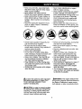
_LLook for this symbol to point out important safety precautions,
It means CAUTION!!! BECOME AWARE!!! YOUR
SAFETY IS INVOLVED,
• Mow up and down slopes (15 ° Max),
not across.
• Remove obstacles such as rocks, tree
limbs, etc.
• Watch for holes, ruts, or bumps. Uneven terra'm could overturn the machine. Tall grass can hide obstacles.
• Use slow speed. Choose a low gear so
that you will not have to stop or shift
while on the slope.
• Avoid starting or stopping on a slope. If
tires lose traction, disengage the
blades and proceed slowly straight
down the slope.
• Do not tum on slopes unless necessary, and then, turn slowly and gradually downhill, if possible.
_tLWARNING- The engine exhaust from
this product contains chemicals known to
the State of California to cause cancer,
birth defects, or other reproductive harm.
_CAUTION"
In order to prevent accidental starting when setting up, transporting,
adjusting or making repairs always disconnect spark plug wire and place wire
where it cannot contact spark plug.
4
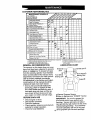
PRODUCT
MAINTENANCE AGREEMENT
SPECIFICATIONS
3ASOLINE
CAPACITY
AND TYPE:
1.25 GALLONS
UNLEADED
REGULAR
A Sears Maintenance
Agreement
is available on this product. Contact your nearest
Sears store for details.
OIL TYPE
API-SF/SG/SH):
SAE IOW30
(above 32°F)
SAE 5W30
(below 32°F)
CUSTOMER
OIL CAPACITY:
W/FILTER:
4.0 PINTS
W/O FILTER: 3.5 PINTS
SPARK PLUG:
GAP: .040")
• Read and observe the safety
• Follow a regular schedule in
ing, caring for and using your
• Follow the instructions under
nance" and "Storage"
owner's manual.
Champion RC12YC
SPEED
FORWARD: 0 - 5.5
REVERSE: 0- 2.4
TIRE PRESSURE:
FRONT: 14 PSI
REAR: 10 PSI
CHARGING
SYSTEM:
5 AMPS BATTERY
3 AMPS HEADLIGHTS
BATTERY:
AMP/HR: 30
MIN. CCA: 240
CASE SIZE: U1R
BLADE BOLT
TORQUE:
rules.
maintaintractor.
=Mainte-
sections of this
_WARNING:
This tractor is equipped
with an internal combustion
engine and
should not be used on or near any unimproved forest-coverad,
brush-covered
or
grass-covered land unless the engine's
exhaust system is equipped with a spark
arrester meeting applicable local or state
laws (if any). If a spark arrester is used, it
should be maintained in effective working
order by the operator.
In the state of California the above is re-
VALVE CLEARANCE: NOT ADJUSTABLE
GROUND
(MPH):
RESPONSIBILITIES
quired by law (Section 4442 of the California Public Resources Code). Other
states may have similar laws. Federal
laws apply on federal lands. A spark atrester for the muffler is available through
your nearest Sears Authorized Service
Center (See REPAIR PARTS section of
this manual).
27-35 FT. LBS.
CONGRATULATIONS
on your purchase
of a Craftsman Tractor. It has been de-"
signed, engineered and manufactured to
give you the best possible dependability
and performance.
Should you experience any problem you
cannot easily remedy, please contact
your nearest Sears Authorized Service
Center. We have competent, well-trained
technicians and the proper tools to service or repair this tractor.
Please read and retain this manual. The
instructions will enable you to assemble
and maintain your tractor properly. Always
observe the "SAFETY RULES".
5
I
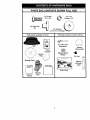
PARTS BAG CONTENTS
SHOWN FULL SIZE
J
II
I
I
(1) Large Flat Washer
(1) Hex Bolt
3/8-16 x 1
0
(1) Lockwasher
3/8
(1) Shoulder Bolt
5/16-18
©
(1) Knob
(1) Washer
17/32 x 1-3/16 x 12 Gauge
6
PARTS BAG CONTENTS
7
!j__
£
(2) Weld Nuts
(2) Screws
#10 x 5/8
SHOWN FULL SIZE
_
(2) Lock
Washers #10
_'
17= ,I
#10
Parts packet separately in carton
Parts Bag contents not shown full size
I
,1-7
Seat
_
(2) Latch Hook
Assemblies
I
Wheel Insert
Cassette
Steering Wheel
Adapter
Mulcher
___/
--'°//
Video
Plate---,_/// /i,
Steo,ng
Whee,-------_ °_
___
q
i
i
Manual
Steering
Boot
'
Steering
(2) Keys
Steering
Extension
Shaft
Pa_s Bag
P
t
I
q
Slope Sheet
i
i
t
I
7
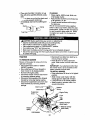
Yournewtractorhas been assembledat the factorywith exceptionof thoseparts left
unassembledfor shipping purposes.To ensuresafe and properoperationof your tractor all parts and hardware you assemble must be tightened securely. Use the correct
tools as necessary to insure proper tightness. Review the video cassette before you
begin.
TOOLS REQUIRED
FOR ASSEMBLY
A socket wrench set will make assembly
easier. Standard wrench sizes you need
are
(1)
(1)
(2)
(1)
listed below.
9/16" wrench
(1) 3/4" Socket w/
drive ratchet
Utility knife
1/2" wrench
(1) Phillips Screwdriver
Tire pressure
gauge
When right or left hand is mentioned in
this manual, it means, from your point of
view, when you are in the operating position (seated behind the steering wheel).
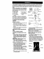
TO REMOVETRACTOR
CARTON
AI'rACH
ROLLING
STEERING
TRACTOR
OFF
WHEEL
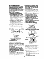
ASSEMBLE
EXTENSION
SHAFT AND
BOOT
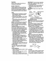
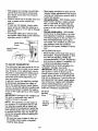
• Slide extension shaft onto lower steering shaft. Align mounting holes in extension and lower shafts and install
5/16 hex bolt and Iocknut. Tighten securely.
IMPORTANT: Tighten bolt and nut securely to 18-22 ft. Ibs. torque.
Place tabs of steedng boot over tab
slots in dash and push down to secure.
INSTALL STEERING WHEEL
• Position front wheels of the tractor so
they are pointing straight forward.
• Slide steering wheel adapter onto
steering shaft extension.
• Position steering wheel so cross bars
are horizontal (left to right) and slide inside boot and onto adapter.
• Assemble large flat washer, 3/8 lock
washer, 3/8 hex bolt and tighten secureh,
• _nap steering wheel
of steering wheel.
Insert
3/8 Hex Bolt
Large
Washer
Loo,wash
__'_'_/
.__
Steering
Steering Wheel
Boot
_Tabs
Extension Shaft
_
Adapter
FROM
UNPACK CARTON
• Remove all accessible
loose parts and
parts cartons from carton.
• Cut, from top to bottom, along lines on
all four corners of carton, and lay panels flat.
• Check for any additional loose parts or
cartons and remove.
BEFORE
SKID
_
insert into center
• Remove protective materials from tractor hood and grill.
IMPORTANT;
Check for and remove any
staples in skid that may puncture tires
where tractor is to roll off skid.
HOW TO SET UP YOUR TRACTOR
CHECK
BATTERY
• Lift seat pan to raised position and
open battery box door.
• If this battery is put into service after
month and year indicated on label (label located between terminals) charge
battery for minimum of one hour at 6-10
amps. (See "BATTERY" in Maintenance
section of this manual for charging instructions).
Seat Pan
Battery
.Terminal
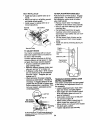
INSTALL
SEAT
TO DRIVE TRACTOR
Adjust seat before tightening adjustment
knob.
• Remove cardboard packing on seat
pan.
• Place seat on seat pan and assemble
shoulder bolt. Tighten shoulder bolt securely.
• Assemble adjustment
knob and flat
washer loosely. Do not tighten.
• Lower seat into operating position and
sit on seat.
• Slide seat until a comfortable
position is
reached which allows you to press
clutch/brake
pedal all the way down.
• Get off seat without moving its adjusted
position.
• Raise seat and tighten adjustment
knob
securely.
Seat
OFF SKID
_-WARNING:
Before starting read, un*
derstand and fo low nstructions n the Operation section of this manual. Be sure
tractor is in a well-ventilated area. Be
sure the area in front of tractor is clear of
other people and objects.
• Be sure all the above assembly steps
have been completed.
• Check engine oil level and fill fuel tank
with gasoline.
• Place freewheel control in =transmission engaged" position.
• Sit on seat in operating position, depress clutch/brake pedal and set the
parking brake.
• Place motion control lever in neutral (N)
position.
ment
its highest
Press lift
liftlever
lever toplunger
and position.
raise attachStart the engine. After engine has
started, move throttle control to idle position.
• Release parking brake.
• Slowly move the motion control lever
forward and slowly drive tractor off skid.
• Apply brake to stop tractor, set parking
brake and place motion control lever in
neutral position.
• Turn ignition key to "OFP position.
Continue with the instructions that follow.
i
Seat Pan
Shoulder
Adjustment'
Knob
Flat Washer
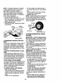
TO ROLLTRACTOR
OFF SKID (See Operation section for location and function
CHECK
TIRE
PRESSURE
The tires on your tractor were overinflated
at the factory for shipping purposes, Correct tire pressure is important for best cutting performance.
• Reduce tire pressure to PSi shown in
"PRODUCT
SPECIFICATIONS"
section
of this manual.
of controls)
ment
its highest
ress lift
liftlever
lever toplunger
and position.
raise attachRelease parking brake by depressing
clutch/brake pedal,
• Place freewheel control in freewheeling
position to disengage transmission
(See =TO TRANSPORT
in the Operation section of this manual),
• Roll tractor forward off skid.
• Remove banding holding discharge
guard up against tractor.
i
CHECK
DECK LEVELNESS
For best cutting results, mower housing
should be propedy leveled. See "TO
LEVEL MOWER HOUSING" in the Service
and Adjustments
9
section of this manual.
CHECK FOR PROPER
ALL BELTS
POSITION
OF
See the figures that are shown for replacing motion and mower blade drive belts
in the Service and Adjustments sectoin of
this manual, Verify that the belts are
muted correctly.
CHECK BRAKE SYSTEM
After you learn how to operate your tractor, check to see that the brake is properly
adjusted. See %0 ADJUST BRAKE" in
the Service and Adjustments
section of
this manual.
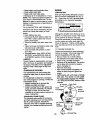
INSTALL MULCHER PLATE
• Install two latch hooks to mulcher plate
using screw, washer, lock washer, and
weld nut as shown.
NOTE: Pre-assemble weld nut to latch
hook by inserting weld nut from the top
with hook pointing down.
• Tighten hardware securely
• Raise and hold deflector shield in upright position.
• Place front of mulcher plate over front
of mower deck opening and slide into
place, as shown.
• Hook front latch into hole on front of
mower deck.
• Hook rear latch into hole on back of
mower deck.
Weld Nut From
The Top
Weld
Nut
Hook Points
Down
Lock
Washer
Latch
Latch
_CAUTION:
Do not remove discharge
guard from mower. Raise and hold guard
when attaching mulcher plate and allow it
to rest on plate while in operation.
TO CONVERT TO BAGGING OR
DISCHARGING
Simply remove mulcher plate and store in
a safe place. Your mower is now ready for
discharging
or installation of optional
grass catcher accessory.
NOTE: It is not necessary to change
blades. The mulcher blades are designed
for discharging
and bagging also.
v' CHECKLIST
PLEASE REVIEW
CHECKLIST:
THE FOLLOWING
6," All assembly instructions have been
completed.
v' No remaining loose parts in carton.
Battery is properly prepared and
charged.
(Minimum 1 hour at 6 amps).
v' Seat is adjusted comfollably
and
tightened
securely.
v' All tires are properly inflated. (For
shipping purposes, the tires were
overinflated
at the fadory).
Be sure mower deck is prop,,.-_rl:_
leveled side-to-side/front.[c,
m;.,r _<_
best cutting results. (Tires must be
properly inflated for leveling).
_" Check mower and drive belts. Be s_re
they are routed properly around
pulleys and inside all belt keepers.
Check wiring. See that all connections
are still secure and wires are properly
clamped.
v' Before driving tractor, be sure freewheel control is in drive position.
WHILE LEARNING HOW TO USE YOUR
TRACTOR, PAY EXTRA ATTENTION TO
THE FOLLOWING
IMPORTANT ITEMS:
Washer
Mulcher
Plate
Lock Washer
Washer
,/
,/
'_¢..f Screw
#'
Deflector
Shield
,/
,/
Latch
Hooks
10
Engine oil is at proper level.
Fuel tank is filled with fresh, clean,
regular unleaded
gasoline.
Become familiar with all controls - their
location and function. Operate them
before you start the engine.
Be sure brake system is in safe operating condition.
It is important to purge the transmission
before operating your tractor for the
first time. Follow proper starting and
transmission
purging instructions (See
"TO START ENGINE" and "PURGE
TRANSMISSION"
in the Operation
section of this manual).
These symbols may appear on your tractor
Learn and understand
their meaning.
BATFERY
ENGINE ON
CAUTION OR
WARNING
REVERSE
ENG#NE OFF
OIL PRESSURE
or in literature
supplied
FORWARD
with the product.
FAST
SLOW
LIGHTS ON
0
FUEL
ATTACHMENT
CLUTCH ENGAGED
CHOKE
REVERSE
MOWER HEIGHT
PARKING BRAKE
LOCKED
N
H
L
NEUTRAL
HIGH
LOW
KEEP AREA CLEAR
IGNITION
ATTACHMENT
CLUTCH DISENGAGED
UNLOCKED
MOWER LIFT
PARKING BRAKE
SLOPE HAZARDS
(SEE SAFETY RULES SECTION)
FREE WHEEL
(A_omatic Modelsonly)
DANGER, KEEP HANDS AND FEET AWAY
11
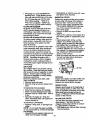
KNOW YOUR TRACTOR
READ THIS OWNER'S
TRACTOR
MANUAL
AND SAFETY
RULES
BEFORE
OPERATING
YOUR
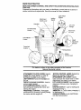
Compare the illustrations with your tractor to familiarize yourself with the locations of
various controls and adjustments. Save this manual for future reference.
Light Switch
Position
Attachment
Clutch Lever
Ignition
Switch
Ammeter
Lift Lever
Plunger
Throttle/Choke
Attachment
Lift Lever
Control
Clutch/Brake
Control
Height
Adjustment
Indicator
Freewheel
Control
Parking Brake
Motion
Control Lever
1 MI
II
Our tractors conform to the safety standards of the American
National Standards Institute.
i
ATTACHMENT
CLUTCH
LEVER:
Used to
engage the mower blades, or other attachments mounted to your tractor.
LIGHT SWITCH: Turns the headlights on
and off.
THROTTLE/CHOKE
CONTROL: Used to
control engine speed.
CLUTCH/BRAKE
PEDAL:
Used for
declutching and braking the tractor and
starting the engine.
FREEWHEEL
CONTROL:
Disengages
transmission for pushing or slowly towing
the tractor with the engine off.
MOTION
CONTROL
LEVER: Selects the
speed and direction of the tractor.
ATTACHMENT
LIFT LEVER: Used to
raise and lower the mower deck or other
attachments mounted to your tractor.
LIFT LEVER PLUNGER: Used to release
attachment
lift lever when changing its
position.
IGNITION SWITCH
fJsed for starting and
stopping the engi.,_.
AMMETER:
Ir.;;cates battery charging (+)
or discharging (-).
PARKING BRAKE: Locks clutch/brake
into the brake position.
12
The operation of any tractor can result in foreign objects thrown into the
eyes, which can result in severe eye damage. Always wear safety glasses
or eye shields while operating your tractor or performing any adjustments
or repairs. We recommend a wide vision safety mask over spectacles, or
standard safety glasses.
HOWTO
USEYOURTRACTOR
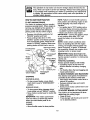
TO SET PARKING BRAKE
Your tractor is equipped with an operator
presence sensing switch. When engine is
running, any attempt by the operator to
leave the seat without first setting the
parking brake will shut off the engine.
• Depress clutch/brake
pedal into full
"BRAKE" position and hold.
• Place parking brake lever in "ENGAGED" position and release pressure
from clutch/brake pedal. Pedal should
remain in "BRAKE" position. Make sure
parking brake will hold tractor secure.
Attachment Clutch
(_horn_
ft/_)1_h __
°
_
_
_
.Brake _
Position'[
'\
"Disengaged"
i \ (,'//'P°siti°n
_
Parking Brake
_,_
-_'\
EnpgoagtieO
_
_',
_._
_ _ )j
/
/---
Clutch/Brake Pedal
"Drive" Position
"Engaged"
NOTE: Failure to move throttle control to
slow position and allowing engine to idle
before stopping may cause engine to
"backfire".
• Turn ignition key to "OFF" position and remove key. Always remove key when leaving tractor to prevent unauthorized use.
• Never use choke to stop engine.
IMPORTANT:
-Leaving the ignition switch
in any position other than "OFF" will
cause the battery to be discharged
(dead).
NOTE: Under certain conditions when
tractor is standing idle with the engine
running, hot engine exhaust gases may
cause "browning" of grass. To eliminate
this possibility, always stop engine when
stopping tractor on grass areas.
_CAUTION:
Always stop tractor completely, as described above, oerore leaving the operator's position, to empty grass
catcher, etc.
THROTTLE
CONTROL
Pos,t,on
Control Lever
"Disengaged"
Position
Always operate engine at full throttle.
• Operating engine at less than full
throttle reduces the battery charging
rate.
• Full throttle offers the best bagging and
mower performance.
TO MOVE FORWARD AND BACKWARD
The direction and speed of movement is
controlled by the motion control lever.
• Start tractor with motion control lever in
neutral (N) position.
• Release parking brake and clutch/
brake pedal.
• Slowly move motion control lever to desired position.
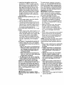
TO ADJUST MOWER CUTTING HEIGHT
STOPPING
MOWER
BLADES
-
• To stop mower blades, move attachment clutch Lever to "DISENGAGED"
position.
GROUND
DRIVE
-
• To stop ground drive, depress clutch/
brake pedal into full "BRAKE" position.
• Move motion control lever to neutral (N)
position.
IMPORTANT:
The motion control lever
The position of the attachment lift lever
determines the cutting height.
• Grasp lift lever.
• Press plunger with thumb and move lever to desired position.
does not return to neutral (N) position
when the clutch/brake pedal is depressed.
ENGINE • Move throttle control to slow position.
13
The cutting
height range is approximately 1-1/2 to 4". The heights are measured from the ground to the blade tip
with the engine not running. These
heights are approximate
and may vary
depending upon soil conditions, height of
grass and types of grass being mowed.
• The average lawn should be cut to approximately 2-1/2 inches during the
cool season and to over 3 inches during hot months. For healthier and better looking lawns, mow often and after
moderate growth.
• For best cutting performance, grass
over 6 inches in height should be
mowed twice. Make the first cut relatively high; the second to desired
height.
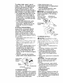
TO ADJUST GAUGE WHEELS
Gauge wheels are properly adjusted
when they are slightly off the ground
when mower is at the desired cutting
height in operating position. Gauge
wheels then keep the deck in proper position to help prevent scalping in most terrain conditions.
• Adjust gauge wheels
flat level surface.
with tractor
o,.q a
, Adjust mower to d,:_sir,-,,dcdttin,3 hoi_l'l
(See "TO ADJUSi
iviOWEt-.; L;U i _il'_G
HEIGHT" in the Operation secticr_ of
this manual).
• With mower in desired height of cut position, gauge wheels should be assembled so they are slightly off the
ground. Install gauge wheel in appropriate hole with shoulder bolt, 3/6
washer, and 3/8-16 Iocknut and tighten
securely.
• Repeat for opposite side installing
gauge wheel in same adjustment
hole.
Gauge Wheel
Mounting ..
Bracket
• Select desired height of cut.
• Start mower blades by engaging attachment clutch control.
• TO STOP MOWER BLADES - disengage attachment clutch control.
_kCAUTION:
Do not operate the mower
without either the entire grass catcher, on
mowers so equipped, or the discharge
guard in place.
Attachment Clutch
Attachment Lift
Lever
Lever High Position
Position
"Disen
Position
I
Position
Discharge
Guard
TO OPERATE
ON HILLS
_kCAUTION:
Do not drive up _r _own
hills with slopes greater ho;', ! _." anJ d,:,
_lot drive across any slot.,{-.-. ;.ls,:_!','le slope
guide provid._d at the '.);_ck of this mai_:!a!
- Choose lhe slowest speed before starling up or down hills.
• Avoid stopping or changing speed on
hills.
• It slowing is necessary, move throttle
control lever to slower position.
• If stopping is absolutely necessary,
push clutch/brake
pedal quickly to
brake position and engage parking
brake.
• Move motion control lever to neutral (N)
position.
IMPORTANT:
The motion control lever
3/8-16
Locknut
-_JShoulder Bolt
3/8 Washer
Wheel
"ro OPERATE
---,, Low
MOWER
Your tractor is equipped with an operator
presence sensing switch, Any attempt by
the operator to leave the seat with the engine running and the attachment clutch
14
engaged will shut off the engine.
does not return to neutral (N) position
when the clutch/brake
pedal is depressed.
• To restart movement, slowly release
parking brake and clutch/brake
pedal.
• Slowly move motion control lever to
slowest setting.
• Make all turns slowly.
TO TRANSPORT
When pushing or towing your tractor, be
sure to disengage transmission
by placing freewheel control in freewheeling
position. Freewheel control is located at the
rear drawbar of tractor.
• Raise attachment
lift to highest position
with attachment lift control.
• Pull freewheel control out and down
into the slot and release so it is held in
the disengaged
position.
• Do not push or tow tractor at more than
two (2) MPH.
• To reengage transmission,
reverse
above procedure.
NOTE: To protect hood from damage
when transporting your tractor on a truck
or a trailer, be sure hood is closed and
secured to tractor. Use an appropriate
means of tying hood to tractor (rope, cord,
etc.).
TOWING CARTS AND OTHER
ATTACHMENTS
Tow only the attachments that are recommended by and comply with specifications of the manufacturer of your tractor.
Use common sense when towing. Too
heavy of a load, while on a slope, is dangerous. Tires can lose traction with the
ground and cause you to lose control of
your tractor.
ADD
• Fill fuel tank. Use fresh, clean, regular
unleaded gasoline with a minimum of
87 octane. (Use of leaded gasoline will
increase carbon and lead oxide deposits and reduce valve life). Do not mix oil
with gasoline. Purchase fuel in quantities that can be used within 30 days to
assure fuel freshness.
IMPORTANT:
When operating in temperatures below 32°F(0°C), use fresh, clean
winter grade gasoline to help insure good
cold weather starting.
_i_WARNING:
Experience indicates that
alcohol blended fuels (called gasohol or
using ethanol or methanol) can attract
moisture which leads to separation and
formation of acids during storage. Acidic
gas can damage the fuel system of an engine while in storage. To avoid engine
problems, the fuel system should be emptied before storage of 30 days or longer.
Drain the gas tank, start the engine and
let it run until the fuel lines and carburetor
are empty. Use fresh fuel next season.
See Storage Instructions for additional information.
Never use engine or carburetor
cleaner products in the fuel tank o_"permanent damage may occur.
-_CAUTION:
Fill to bottom of gas tank
filler neck. Do not overfill. Wipe on any
spilled oil or fuel. Do not store, spill or use
gasoline near an open flame.
TO START ENGINE
BEFORE STARTING THE ENGINE
CHECK
ENGINE
GASOLINE
When starting the engine for the first time
or if the engine has run out of fuel, it will
take extra cranking time to move fuel from
the tank to the engine.
• Be sure freewheel control is in the
transmission
engaged position.
• Sit on seat in operating position, depress clutch/brake
pedal and set parking brake.
• Place motion control lever in neutral (N)
positien.
• Move attachment clutch to "DISEN-
OIL LEVEL
• The engine in your tractor has been
shipped, from the factory, already filled
with summer weight oil.
• Check engine oil with tractor on level
ground.
• Unthread and remove oil fill cap/dipstick; wipe oil off. Reinsert the dipstick
into the tube and rest oil fill cap on the
tube. Do not thread the cap onto the
tube. Remove and read oil level. If necessary, add oil until "FULL" mark on
dipstick is reached. Do not overfill.
• For cold weather operation you should
change oil for easier starting (See "OIL
VISCOSITY CHART" in the Maintenance section of this manual).
• To change engine oil, see the Maintenance section in this manual.
GAGED" position.
• Move throttle control to choke position.
NOTE: Before starting, read the warm and
cold starting procedures
below.
15
•
Insert key into ignition and turn key
clockwise to "START" position and release key as soon as engine starts. Do
not run starter continuously
for more
than fifteen seconds per minute. If the
engine does not start after several attempts, move throttle control to fast position, wait a few minutes and try again.
If engine still does not start, move the
throttle control back to the choke position and retry.
WARM WEATHER STARTING (50 ° F and
above)
• When engine starts, move the throttle
control to the fast position.
• The attachments
and ground drive can
now be used. If the engine does not accept the load, restart the engine and allow it to warm up for one minute using
the choke as described above.
COLD WEATHER STARTING ( 50 ° F and
below)
• When engine starts, allow engine to run
with the throttle control in the choke position until the engine runs roughly, then
move throttle control to fast position,
This may require an engine warm-up
period from several seconds to several
minutes, depending
on the temperature.
AUTOMATIC TRANSMISSION
WARM UP
• Before driving the unit in cold weather,
the transmission
should be warmed up
as follows:
• Be sure the tractor is on level ground.
• Place the motion control lever in neutral. Release the parking brake and
let the clutch/brake
slowly return to
operating position.
• Allow one minute for transmission
to
warm up. This can be done during the
engine warm up period.
• The attachments
can also be used during the engine warm-up period after the
transmission
has been warmed up.
NOTE: At a high altitude (above 3000
feet) or in cold temperatures
(below 32 F)
the carburetor fuel mixture may need to
be adjusted for best engine performance.
See "TO ADJUST CARBURETOR"
in the
Service and Adjustments
section of this
manual.
PURGE TRANSMISSION
_IiCAUTION:
Never engage or disengage freewheel
lever while the engine
running.
is
To ensure proper operation and performance, it is recommended
that the transmission be purged before operating tractor for the first time. This procedure will remove any trapped air inside the transmission which may have developed during
shipping of your tractor.
IMPORTANT:
Should your transmission
require removal for service or replacement, it should be purged after reinstallation before operating the tractor.
• Place tractor safely on level surface
with engine off and parking brake set.
• Disengage
transmission
by placing
freewheel control in freewheeling
position (See "TO TRANSPORT"
in this section of manual).
• Sitting in the tractor seat, start engine.
After the engine is running, move
throttle control to slow position. With
motion control lever in neutral (N) position, slowly disengage clutch/brake
pedal.
• Move motion control lever to full forward
position and hold for five (5) seconds.
Move lever to full reverse position and
hold for five (5) seconds. Repeat this
procedure three (3) times.
NOTE: During this procedure there will be
no movement of drive wheels. The air is
being removed from hydraulic drive system.
• Move motion control lever to neutral (N)
position. Shut off engine and set parking brake.
• Engage transmission by placing freewheel control in driving position (See
"TO TRANSPORT"
in this section of
manual).
• Sitting in the tractor seat, start engine.
After the engine is running, move
throttle control to half (1/2) speed. With
motion control lever in neutral (N) position, slowly disengage clutch/brake
pedal.
• Slowly move motion control lever forward; after the tractor moves approximately five (5) feet, slowly move motion
control lever to reverse position, After
the tractor moves approximately
five (5)
feet return the motion control lever to
the neutral (N) r._3ition. Repeat this procedure with the motion control lever
three (3) times.
• Your tractor is now purged and ready for
normal operation.
16
MOWING
TIPS
• Mower should be properly leveled for
best mowing performance.
See 'q'O
LEVEL MOWER HOUSING" in the Service and Adjustments
section of this
manual.
• The left hand side of mower should be
used for trimming.
• Drive so that clippings are discharged
onto the area that has been cut. Have
the cut area to the right of the tractor.
This will result in a more even distribution of clippings and more uniform cutting.
• When mowing large areas, start by turning to the right so that clippings will discharge away from shrubs, fences, driveways, etc. After one or two rounds, mow
in the opposite direction making left
hand turns until finished.
• If grass is extremely tall, it should be
mowed twice to reduce load and possible fire hazard from dried clippings.
Make first cut relatively high; the second
to the desired height.
• Do not mow grass when it is wet. Wet
grass will plug mower and leave undesirable clumps. Allow grass to dry before mowing.
• Always operate engine at full throttle
when mowing to assure better mowing
performance and proper discharge of
material. Regulate ground speed by selecting a low enough gear to give the
mower the best cutting performance as
well as the quality of cut desired.
• When operating attachments, select a
ground speed that will suit the terrain
and give best performance of the attachment being used.
MULCHING
MOWING
TIPS
IMPORTANT:
For best performance,
keep
mower housing free of built-up grass and
trash. Clean after each use.
• The special mulching blade will recur
the grass clippings many times and reduce them in size so that as they fall
onto the lawn they will disperse into the
grass and not be noticed. Also, the
mulched grass will biodegrade quickly
to provide nutrients for the lawn. Always
mulch with your highest engine (blade)
speed as this will provide the best recutting action of the blades.
• Avoid cutting your lawn when it is wet.
Wet grass tends to form clumps and interferes with the mulching action. The
best time to mow your lawn is the early
afternoon. At this time the grass has
dried and the newly cut area will not be
exposed to the direct sun.
• For best results, adjust the mower cutting height so that the mower cuts off
only the top one-third of the grass
blades. For extremely heavy mulching,
reduce your width of cut on each pass
and mow slowly.
• Certain types of grass and grass conditions may require that an area be
mulched a second time to completely
hide the clippings. When doing a second cut, mow across or perpendicular
to the first cut path.
• Change your cutting pattern from week
to week. Mow north to south one week
then change to east to west the next
week. This will help prevent matting and
graining of the lawn.
Max 1/3
17
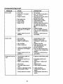
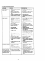
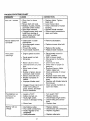
CUSTOMER RESPONSIBILITIES
BE 0 .e
SERV,OE
.......DATES
i
ChockBr.oO.,ation
Check Tire Pressure
Check Operator Presence and
Interlock Systems
T
R
Check for Loose Fasteners
Sharpen/Replace
Mower Blades
T
Lubncation Chart
0
Check Battery Level
R
Clean Battery and Terminals
Check Transaxle Cooling
Adjust Blade Belt(s) Tension
! Adjust Motion Drive Ball(s) Tension
Cheek Engine Oil Level
Change Engine Oil
E
N
G
Clean Air Filter
Clean Air Screen
Inspect Muffler/Spark
Arrester
Replace Oil Filter (If equipped)
E
Clean Engir_e Cooling Fins
Replace Spark PI_J
Replace Ai: Filter Paper Cartridge
Replace Fuel Filter
2.Sen,_cemoteoflenwhenoperatingind_tlyordu_tyconditlons
6 No_ t equirad il equippet_ with m_}ntenance-hee battery
7 - Tighlen fronl axle 13ivolboll to 35 tl-IUS maximum
3 - I1equipped wilh oil f_ltsr* change o[I every 50 hc_is
4 - RePlace blades more often when mowing in sandy soil
GENERAL
RECOMMENDATIONS
The warranty on this tractor does not cover
items that have been subjected to operator
abuse or negligence. To receive full value
from the warranty, operator must maintain
tractor as instructed in this manual. Some
adjustments
will need to be made periodically to properly maintain your tractor.
All adjustments
in the Service and Adjustments section of this manual should be
checked at least once each season.
Do not ovemghten
LUBRICATION
(_)Spindle ._-:-:_.
f'_
Zerk
CHART
r---Spindle
Zerk(_
_,_=.::=:::::
_'_;1
-.._
_
.... I
_
.._
..._
Bearing zerk
,_ .....
j
Front Wheel
';'"
i
Front Wheel 1(3)
_
. "-,
_eanng/--eFK
Engine (_
• Once a year you should replace the
spark plug, clean or replace air filter,
and check blades and belts for wear. A
new spark plug and clean air filter assure proper air-fuel mixture and help
your engine run better and last longer.
BEFORE
•
•
•
•
EACH
USE
Check engine oil level.
Check brake operation.
Check tire pressure.
Check operator presence and interlock
systems for proper operation.
* Check for loose fasteners,
i
•
l_)General Purpose Grease
_Refer
to Maintenance
"ENGINE"
Section
IMPORTANT:
Do not oil or grease the
pivot points which have special nylon
bearings.
Viscous lubricants will attract
dust and dirt that will shorten the life of the
self-lubricating
bearings.
If you feel they
must be lubricated, use only a dry, pew1 8 dered graphite
type lubricant
sparingly.
TRACTOR
Always observe safety rules when performing any maintenance.
BRAKE
IMPORTANT:
To ensure proper assembly,
center hole in blade must align with star
on mandrel assembly.
• Reassemble hex bolt, lock washer and
flat washer in exact order as shown.
OPERATION
• Tighten bolt securely (27-35 Ft. Lbs.
torque).
IMPORTANT:
Blade bolt is Grade 8 heat
treated.
If tractor requires more than six (6) feet
stopping distance at high speed in highest gear, then brake must be adjusted.
(See "TO ADJUST BRAKE" in the Service
and Adjustments section of this manual).
Trailing
Blade
EdgeUP"b-. 7
TIRES
• Maintain proper air pressure in all tires
(See "PRODUCT SPECIFICATIONS"
section of this manual).
• Keep tires free of gasoline, oil, or insect
control chemicals which can harm rubber.
• Avoid stumps, stones, deep ruts, sharp
objects and other hazards that may
cause tire damage.
Hex Bolt
(Grade 8)_
_'_.
identified by six lines on the bolt head.
TO SHARPEN BLADE
NOTE: We do not recommend sharpening
blade, but if you do, be sure the blade is
balanced.
Care should be taken to keep the blade
balanced. An unbalanced blade will
cause excessive vibration and eventual
may be purchased from your local parts
dealer. Tire sealant also prevents tire dry
rot and corrosion.
PRESENCE
Center_Ah_,_
",_. "Star
"-"% "}_-,
Flat Washer "_*A Grade 8 heat treated bolt can be
NOTE: To seal tire punctures and prevent
flat tires due to slow leaks, tire sealant
OPERATOR
_(_
_ -_
Mandrel Assembly
damage to mower and engine.
• The blade can be sharpened with a file
or on a grinding wheel. Do not attempt
to sharpen while it is on the mower.
• To check blade balance, you will need
a 5/8" diameter steel bolt, pin, or a cone
balancer. (When using a cone balancer,
follow the instructions supplied with balancer).
NOTE: Do not use a nail for balancing
blade. The lobes of the center hole may
appear to be centered, but are not.
• Slide blade onto an unthreaded portion
of the steel bolt or pin and hold the bolt
or pin parallel with the ground. If blade
is balanced, it should remain in a horizontal position. If either end of the blade
moves downward,
sharpen the heavy
end until the blade is balanced.
SYSTEM
Be sure that operator presence and interlock systems are working properly. If your
tractor does not function as described below, repair the problem immediately.
• The engine should not start unless the
clutch/brake pedal is fully depressed
and attachment clutch control is in the
disengaged position.
• When the engine is running, any attempt by the operator to leave the seat
without first setting the parking brake
should shut off the engine.
• When the engine is running and the attachment clutch is engaged, any attempt by the operator to leave the seat
should shut off the engine.
• The attachment clutch should never operate unless the operator is in the seat.
BLADE CARE
Center Hole
For best results mower blades must be
kept sharp. Replace bent or damaged
blades.
BLADE
REMOVAL
• Raise mower to highest position to allow
access to blades.
• Remove hex bolt, lock washer and flat
washer securing blade.
• Install new or resharpened
blade with
trailing edge up towards deck as shown.
19
BATTERY
Your tractor has a battery charging system
which is sufficient for normal use, However, periodic charging of the battery with
an automotive charger will extend its life.
• Keep battery and terminals clean.
• Keep battery bolts tight.
• Keep small vent holes open.
• Recharge at 6-10 amperes for 1 hour.
NOTE: The original equipment battery on
your tractor is maintenance free. Do not
attempt to open or remove caps or covers.
Adding or checking level of electrolyte is
not necessary.
TO CLEAN
BATTERY
ENGINE
LUBRICATION
Only use high quality detergent oil rated
with API service classification SF, SG, or
SH. Select the oil's SAE viscosity grade
according to your expected operating
temperature.
AND TERMINALS
Corrosion and dirt on the battery and terminals can cause the battery to "leak"
power.
• Open battery box door.
• Disconnect BLACK battery cable first
then RED battery cable and remove
battery from tractor.
• Rinse the battery with plain water and
dry.
• Clean terminals and battery cable ends
with wire brush until bright.
• Coat terminals with grease or petroleum jelly.
• Reinstall battery (See "REPLACING
BATTERY" in the SERVICE AND ADJUSTMENTS
section of this manual),
V-BELTS
Check V-belts for deterioration and wear
after 100 hours of operation and replace if
necessary. The belts are not adjustable.
Replace belts if they begin to slip from
wear.
TRANSAXLE
COOUNG
The transmission fan and cooling fins
should be kept clean to assure proper
cooling.
Do not attempt to clean fan or transmission while engine is running or while the
transmission is hot.
• Inspect cooling fan to be sure fan
blades are intact and clean.
• Inspect cooling fins for dirt, grass clippings and other materials. To prevent
damage to seals, do not use compressed air or high pressure sprayer to
clean cooling fins.
_N_
-c ._
ISAEVIS_:OSITY GRAOES
.=o. .,o.
;,.
_o-
;o-
_.
,_.
Change the oil after every 50 hours of operation or at least once a year if the tractor
is not used for 50 hours in one year.
Check the crankcase oil level before starting the engine and after each eight (8)
hours of operation.
Tighten oil fill cap/dipstick securely each time you check the oil
level.
TO CHANGE
ENGINE
OIL
Determine temperature range expected
before oil change. All oil must meet API
service classification
SF, SG, or SH.
• Be sure tractor is on level surface.
• Oil will drain more freely when warm.
• Catch oil in a suitable container.
• Remove oil fill cap/dipstick.
Be careful
not to allow dirt to enter the engine
when changing oil.
• Remove drain plug.
• After oil has drained completely, replace oil drain plug and tighten securely.
• Refill engine with oil through oil fill dipstick tube. Pour slowly. Do not overfill.
For approximate capacity see =PRODUCT SPECIFICATIONS"
section of this
manual.
Air Cleaner
Cover Knob
Foam Cover
Nut
Rubber
Grommet
TRANSAXLE
PUMP FLUID
The transaxle was sealed at the factory
and fluid maintenance is not required for
the life of the transaxle. Should the
transaxle ever leak or require servicing,
contact your nearest authorized service
center.
Base
Air Cleaner
Paper
Cartridge
20
Dipstick
Drain Plug
• Use gauge on oil fill cap/dipstick for
checking level. Insert dipstick into the
tube and rest the oil fill cap on the tube.
Do not thread the cap onto the tube
when taking reading. Keep oil at
=FULL" line on dipstick. Tighten cap
onto the tube securely when finished.
CLEAN AIR SCREEN
Air screen must be kept free of dirt and
chaff to prevent engine damage from
overheating. Clean with a wire brush or
compressed air to remove did and stubbom dried gum fibers.
CLEAN AIR INTAKE/COOLING
AREAS
To insure proper cooling, make sure the
grass screen, cooling fins, and other external surfaces of the engine are kept
clean at all times.
Every f 00 hours of operation (more often
under extremely dusty, dirty conditions),
remove the blower housing and other
cooling shrouds. Clean the cooling fins
and external surfaces as necessary. Make
sure the cooling shrouds are reinstalled.
NOTE:
Operating the engine with a
blocked grass screen, dirty or plugged
cooling fins, and/or cooling shrouds removed will cause engine damage due to
overheating.
AIR FILTER
Your engine will not run properly using a
dirty air filter. Clean the foam pre-cleaner
after every 25 hours of operation or every
season. Service paper cartridge every
100 hours of operation or every season,
whichever occurs first.
Service air cleaner more often under
dusty conditions.
• Remove knob and cover.
• Remove wing nut and air cleaner from
base.
TO SERVICE
• Reassemble air cleaner, wing nut, cover
and tighten knob securely.
ENGINE
Replace the engine oil filter every season
or every other oil change if the tractor is
used more than 100 hours in one year.
• Drain oil from engine crankcase (See
=TO CHANGE ENGINE OIL" in this section of this manual, through step remove drain plug).
• Remove oil filter and wipe off filter
adapter.
• Apply a thin coating of new engine oil to
the rubber gasket on replacement oil filter.
• Install replacement oil filter on filter
adapter. Turn oil filter clockwise until
rubber gasket contacts the filter adapter,
then tighten filter an additional 1/2 tum.
• Fill crankcase with new oil (See =TO
CHANGE ENGINE OIL" in this section of
this manual). For approximate capacity
see =PRODUCT SPECIFICATIONS"
section of this manual.
• Start the engine and check for oil leaks.
Correct any leaks before placing engine into full operation.
Filter
MUFFLER
Inspect and replace corroded muffler and
spark arrester (if equipped) as it could
create a fire hazard and/or damage.
SPARK
PLUGS
Replace spark plugs at the beginning of
each mowing season or after every 100
hours of operation, whichever occurs first.
Spark plug type and gap setting are
shown in =PRODUCT SPECIFICATIONS"
section of this manual.
PRE-CLEANER
• Slide foam pre-cleaner off cartridge.
• Wash it in liquid detergent and water.
• Squeeze it dry in a clean cloth. Allow it
to dry.
• Saturate it in engine oil. Wrap it in
clean, absorbent cloth and squeeze to
remove excess oil.
IN-LINE FUEL FILTER
The fuel filter should be replaced once
each season. If fuel filter becomes
clogged, obstructing fuel flow to carburetor, replacement is required.
° With engine cool, remove filter and plug
fuel line sections.
TO SERVICE CARTRIDGE
• Replace a dirty, bent, or damaged cartridge.
NOTE: Do not wash the paper cartridge
or use pressurized air, as this will damage
the cartddge.
• Reinstall the pre-cleaner (cleaned and
oiled) over the paper cartddge.
OIL FILTER
21
• Place new fuel filter in position in fuel
line with arrow pointing towards carburetor.
'_ ._,,re there are no fuel line leaks and
..... ,_s are properly positioned.
Immediately wipe up any spilled gasoline.
CLEANING
• Clean engine, battery, seat, finish, etc.
of all foreign matter.
• Keep finished surfaces and wheels free
of all gasoline, oil, etc.
• Protect painted surfaces with automotive type wax.
We do not recommend using a garden
hose to clean your tractor unless the electrical system, muffler, air filter and carburetor are covered to keep water out. Water
in engine can result in a shortened engine life.
,_CAUTION:
Before performing any service or adjustments:
• Depress clutch/brake pedal fully and set parking brake.
• Place motion control lever in neutral (N) position.
• Place attachment clutch in "DISENGAGED"
position.
• Turn ignition key "OFF" and remove key.
• Make sure the blades and all moving parts have completely stopped.
• Disconnect
spark plug wire from spark plug and place wire where it cannot come
in contact with plug.
i
TRACTOR
TO REMOVE
MOWER
Mower will be easier to remove from the
right side of tractor.
• Place attachment clutch in "DISENGAGED" position.
• Move attachment lift lever forward to
lower mower to its lowest position.
• Roll belt off engine pulley.
• Disconnect clutch rod from clutch lever
by removing retainer spring.
• Disconnect anti-swaybar from chassis
bracket by removing retainer spring.
• Disconnect suspension arms from rear
deck brackets by removing retainer
springs.
Clutcl
ilia
• Disconnect front links from deck by removing retainer springs.
• Raise lift lever to raise suspension
arms. Slide mower out from under tractor.
IMPORTANT:
If an attachment other than
the mower deck is to be mounted on the
tractor, remove the front links.
TO INSTALL MOWER
• Raise attachment lift lever to its highest
position.
• Slide mower under tractor with discharge guard to right side of tractor.
• Lower lift lever to its lowest position.
° Install mower in reverse order of removal instructions.
Retainer
Clutch
Suspension
Arms
Engine Pulley
Front
Link
Retainer Springs
(Both Sides)
;pdngs
(Both Sides)
Retainer
Spdng
Anti-Swaybar
22
TO LEVEL MOWER
HOUSING
Adjust the mower while tractor is parked
on level ground or driveway. Make sure
tires are properly inflated (See =PRODUCT SPECIFICATIONS").
If tires are over
or underinflated, you will not properly adjust your mower.
SIDE-TO-SIDE
• Before making any necessary adjustments, check that both front links are
equal in length. Both links should be
approximately 10-3/8".
If links are not equal in length, adjust
one link to same length as other link.
To lower front of mower loosen nut "E"
on both front links an equal number of
turns.
When distance "D" is 1/8" to 1/2" lower
at front than rear, tighten nuts "F"
against trunnion on both front links.
To raise front of mower, loosen nut "F"
from trunnion on both front links.
•
•
ADJUSTMENT
• Raise mower to its highest position.
• At the midpoint of both sides of mower,
measure height from bottom edge of
mower to ground. Distance =A" on both
sides of mower should be the same or
within 1/4" of each other.
• If adjustment is necessary, make adjustment on one side of mower only.
• To raise one side of mower, tighten lift
link adjustment nut on that side.
• To lower one side of mower, loosen lift
link adjustment nut on that side.
•
•
Tighten nut "E" on both front links an
equal number of turns.
• When distance "D" is 1/8' to 1/2" lower
at front than rear, tighten nut "F" against
trunnion on both front links.
• Recheck side-to-side
Mandrel
NOTE:
Each full turn of adjustment nut
will change mower height about 1/8".
• Recheck measurements
ing.
Bottom Edge of
Mower to
adjustment.
after adjustBottom Edge of
Mower to
Both Front LinksShould be Equal in Length
Groun6_round
Suspension
Trunnion "_
Lilt _-Nut "F"._
FRONT-TO-BACK
_ut
=E"
ADJUSTMENT
IMPORTANT:
Deck must be level side-toside. If the following front-to-back adjustment is necessary, be sure to adjust both
front links equally
so mower
will stay
level side-to-side.
To obtain the best cutting results, the
mower housing should be adjusted so
that the front is approximately 1/8" to 1/2"
lower than the rear when the mower is in
its highest position.
Check adjustment on right side of tractor.
Measure distance =D" directly in front and
behind the mandrel at bottom edge of
mower housing as shown.
Front Links
TO REPLACE MOWER BLADE DRIVE
BELT (See Illustration Next Page)
The mower blade drive belt may be replaced without tools. Park the tractor on
level surface. Engage parking brake.
BELT REMOVAL• Remove mower from tractor (See "TO
REMOVE MOWER" in this section of
this manual).
• Work belt off both mandrel pulleys and
idler pulleys.
• Pull belt away from mower.
23
BELTINSTALLATION -
TO REPLACE
• Install new belt in reverse order of removal.
• Make sure belt is in all pulley grooves
and inside all belt guides.
• Install mower in reverse order of removal instructions.
Park the tractor on level surface. Engage
parking brake. For assistance, there is a
belt installation guide decal on bottom
side of left footrest.
• Remove mower (See "TO REMOVE
MOWER" in this section of this manual.)
• Remove belt from stationary idler and
clutching idler.
• Pull belt slack toward rear of tractor,
Carefully remove belt upwards from
transmission input pulley and over cooling fan blades.
• Pull belt toward front of tractor and re-
Mandrel
Pulley
Idler Pulleys
MOTION
DRIVE BELT
move downward from around engine
pulley,
• Install new belt by reversing above procedure.
Mandrel Pulley
TO ADJUST
Engine ____.._____
Pulley
BRAKE
Clutching
Idler
Your tractor is equipped with an adjustable brake system which is mounted on
the side of the transaxle,
If tractor requires more than six (6) feet
stopping distance at high speed in highest gear, then brake must be adjusted.
• Depress clutch/brake pedal and engage parking brake.
• Measure distance between brake operating arm and nut "A" on brake rod.
• If distance is other than 1-9/16", loosen
Transmission
Input Pulley_
0
jam nut and turn nut =A" until distance
becomes 1-9/16". Retighten jam nut
against nut "A".
• Road test tractor for proper stopping
distance as stated above. Readjust if
necessary.
If stopping distance is still
greater than six (6) feet in highest gear,
further maintenance is necessary. Contact your nearest authorized service
center/department.
W'_h PKldng
Brake Engaged
-@
Stationary Idler_
'I"RANO_IU(LE
MOTION OC:)NTROL
LEVER
NEUTRAL ADJUSTMENT
The motion control lever has been preset
at the factory and adjustment should not
be necessary.
• Loosen adjustment bolt in front of the
right rear wheel, and lightly tighten.
• Start engine and move motion control
lever until tractor does not move forNut
ward or backward.
• Hold motion control lever in that position and turn engine off.
• While holding motion control lever in
place, loosen the adjustment bolt.
• Move motion cor_.trollever to the neutral
- Operating
(N) (lock gate) position.
Arm
• Tighten adjustment bolt securely.
Do Not touChthis nut. If further brake adjustment is
necessary_ontact yournearestauthorizedservice
center/department
24
NO=rE:If additionalclearance
is needed
to get to adjustment bolt, move mower
deck height to the lowest position.
After above adjustment is made, if the
tractor still creeps forward or backward
while motion control lever is in neutral position, follow these steps:
• Loosen the adjustment bolt.
• Move the motion control lever 1/4 to 1/2
inch in the direction it is trying to creep.
• Tighten adjustment bolt securely.
• Start engine and test.
• If tractor still creeps, repeat above steps
until satisfied.
Motion
Lever
• On rear wheels only: align grooves in
rear wheel hub and axle. Insert square
key.
• Replace washers and snap retaining
ring securely in axle groove.
• Replace axle cover,
NOTE: To seal tire punctures and prevent
flat tires due to slow leaks, tire sealant
may be purchased from your local parts
dealer. Tire sealant also prevents tire dry
rot and corrosion.
Washers_
Retaining
_f_'_'_
Neutral
Lock Gate
Axle Cover
=_-' Square Key
(Rear Wheel Only)
TO START ENGINE WITH AWEAK
BATrERY
Adjustment
TRANSMISSION
MENT
_iLCAUTION:
Lead-a:cid batteries generate explosive gases. Keep sparks, flame
and smoking materials away from batteries. Always wear eye protection when
around batteries.
Bolt
REMOVAL!REPLACE-
Should your transmission require removal
for service or replacement, it should be
purged after reinstallation and before operating the tractor. See "PURGE TRANSMISSION" in the Operation section of this
manual.
TO ADJUST
MENT
STEERING
WHEEL
If your battery is too weak to start the engine, it should be recharged. (See "BATTERY" in the MAINTENANCE
section of
this manual).
If "jumper cables" are used for emergency
starting, follow this procedure:
IMPORTANT:
Your tractor Is equipped
with a 12 volt negative grounded system.
The other vehicle must also be a 12 volt
ALIGN-
If steering wheel crossbars are not horizontal (left to right) when wheels are positioned straight forward, remove steering
wheel and reassemble per instructions in
the Assembly section of this manual.
negative grounded system. Do not use
your tractor battery to start other vehicles.
TO ATFACH
• Connect
FRONT WH EEL TOE-IN/CAMBER
The front wheel toe-in and camber are not
CABLES
-
the POSITIVE (+) terminal of each battery, taking care not to short against
chassis.
• Connect one end of the BLACK cable to
adjustable on your tractor. If damage has
occurred to affect the front wheel toe-in or
camber, contact your nearest authorized
service center/department.
TO REMOVEWHEEL
JUMPER
each end of the RED cable to
the NEGATIVE (-) terminal of fully
charged battery.
• Connect the other end of the BLACK
FOR REPAIRS
cable to good CHASSIS GROUND,
away from fuel tank and battery.
• Block up axle securely.
• Remove axle cover, retaining ring and
washers to allow wheel removal (rear
wheel contains a square key - Do not
lose).
• Repair tire and reassemble.
TO REMOVE
DER • BLACK
CABLES,
REVERSE
cable first from chassis
ORand
then from the fully charged battery.
• RED cable last from both batteries.
25
Positiw Terminal
Negative Terminal
TO REPLACE HEADLIGHT
BULB
• Raise hood.
• Pull bulb holder out of the hole in the
backside of the grill.
• Replace bulb in holder and push bulb
holder securely back into the hole in the
backside of the grill.
• Close hood.
INTERLOCKS
Battery
PositiveTerminal
Negative Terminal
REPLACING BA'I'rERY
_CAUTION:
Do not short battery terminals by allowing a wrench or any other
object to contact both terminals at the
same time. Before connecting battery, remove metal bracelets, wristwatch
bands, rings ,etc.
Positive terminal must be connected first
to prevent sparking from accidental
grounding.
• Lift seat pan to raised position and
open battery box door.
• Disconnect BLACK battery cable first
then RED battery cable and carefully
remove battery from tractor.
• Install new battery with terminals in
same position as old battery.
• First connect RED battery cable to positive (+) terminal with hex bolt and keps
nut as shown. Tighten securely.
• Connect BLACK grounding cable to
negative (-) terminal with remaining hex
bolt and keps nut. Tighten securely.
• Close battery box door.
Seat
Battery Box
Door
Positive (Red) Cable
AND RELAYS
Loose or damaged wiring may cause your
tractor to run poorly, stop running, or prevent it from starting.
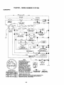
• Check wiring. See electrical wiring diagram in the Repair Parts section.
TO REPLACE
FUSE
Replace with 15 amp automotive-type
plug-in fuse. The fuse holder is located
behind the dash.
TO REMOVE HOOD AND GRILL
ASSEMBLY
• Raise hood.
• Unsnap headlight wire connector.
• Stand in front of tractor. Grasp hood at
sides, tilt toward engine and lift off of
tractor.
• To replace,
reverse above procedures.
Headlight
Wire
Connector
ENGINE
Maintenance, repair, or replacement of
the emission control devices and systems,
which are being done at the customers
expense, may be performed by any nonroad engine repair establishment or individual. Warranty repairs must be performed by an authorized engine
manufacturer's service outlet.
TO ADJUSTTHRO'I-FLE
CONTROL
CABLE
The throttle control has been preset at the
factory and adjustment should not be necBolt
essary. Check adjustment as described
below before loosening cable. If adjustNegative (Black)
26 merit is necessary, proceed as follows:
Cable
•
• Start engine and allow to warm for five
minutes. Make adjustments with engine
running and shift/motion control lever in
neutral (N) position.
Idle speed setting - With throttle control
lever in slow position, engine should
idle at 1750 RPM. If engine idles too
slow or fast, turn idle speed adjusting
screw in or out until correct idle is attained.
With engine not running, move throttle
control lever from slow to choke position. Slowly move lever from choke to
fast position.
• Check to see if hole in throttle lever and
hole in speed control bracket are
aligned.
• If holes are not aligned, loosen cable
clamp screw and align the holes by inserting a pencil or a 1/4" drill bit through
both holes.
• Idle fuel needle f_e_tin9 - With throttle
control lever in slow position, turn idle
fuel adjustment
needle In (clockwise)
until engine begins to die and then turn
out (counterclockwise)
until engine
runs rough. Turn needle to a point midway between those two positions.
• Recheck idle speed. Readjust if necessary.
• Pull throttle cable up to remove slack
and tighten cable clamp screw. Remove
alignment
pencil or drill bit.
Cabl,
Screw
Speed Control
Bracket
ACCELERATION
• Move throttle
fast position. If engine hesitates or dies,
turn idle fuel adjusting needle out
(counterclockwise) 1/8 turn. Repeat test
and continue to adjust, if necessary, until engine accelerates
smoothly.
High speed stop is factory adjusted. Do
not adjust - damage may result.
IMPORTANT:
Never tamper with the engine governor, which is factory set for
proper engine speed. Overspeeding the
engine above the factory high speed setting can be dangerous.
If you think the engine-governed
high speed needs adjusting, contact your nearest AUTHORIZED
service center/department,
which has
proper equipment
and experience
to
make any necessary adjustments.
Thrott
TO ADJUST
CARBURETOR
The carburetor has been preset at the factory and adjustment should not be necessary. However, minor adjustment
may be
required to compensate for differences in
fuel, temperature, altitude or load. If the
carburetor does need adjustment, proceed as follows:
In general, turning the adjusting needles
in (clockwise) decreases the supply of
fuel to the engine giving a leaner fuel/air
mixture. Turning the adjusting needles out
(counterclockwise)
increases the supply
of fuel to the engine giving a richer fuel/air
mixture.
IMPORTANT:
Damage to the needles
the seats in carburetor may result if
needle is turned in too tight.
TEST control lever from slow to
and
Idle Speed
Adjusting
Screw
Idle Fuel
Adjusting
Needle
NOTE: The carburetor on this engine is
low emission. It is equipped with an idle
fuel adjusting needle with a limiter cap,
which allows some adjustment within the
limits allowed by the cap. Do not attempt
to remove the limiter cap. The limiter cap
cannot be removed without breaking the
adjusting needle.
• Be sure you have a clean air filter and
the throttle control cable is adjusted
properly (see above). •
27
Immediately prepare your tractor for storage at the end of the season or if the tractor will not be used for 30 days or more.
Also, experience
indicates that alcohol
blended fuels (called gasohol or using
ethanol or methanol) can attract moisture
which leads to separation and formation of
acids during storage. Acidic gas can damage the fuel system of an engine while in
storage.
• Drain the fuel tank.
_I, CAUTION: Never store the tractor with
gasoline in the tank inside a building
where fumes may reach an open flame or
spark. Allow the engine to cool before storing in any enclosure.
TRACTOR
Remove mower from tractor for winter storage. This will allow you to clean it thoroughly. Remove all dirt, grease, leaves,
etc. Store in a clean, dry area.
• Clean entire tractor (See "CLEANING"
in
the Maintenance
section of this manual).
• Inspect and replace belts, if necessary
(See belt replacement
instructions in the
Service and Adjustments
section of this
manual).
• Lubricate as shown in the Maintenance
section of this manual.
• Be sure that all nuts, bolts and screws
are securely fastened. Inspect moving
parts for damage, breakage and wear.
Replace if necessary.
• Touch up all rusted or chipped paint surfaces; sand lightly before painting.
BATTERY
• Start the engine and let it run until the
fuel lines and carburetor are empty.
• Never use engine or carburetor
cleaner
products in the fuel tank or permanent
damage may occur.
• Use fresh fuel next season.
NOTE: Fuel stabilizer is an acceptable alternative in minimizing the formation of
fuel gum deposits during storage. Add stabilizer to gasoline in fuel tank or storage
container. Always follow the mix ratio
found on stabilizer container. Run engine
at least 10 minutes after adding stabilizer
to allow the stabilizer to reach the carburetor. Do not drain the gas tank and carburetor if using fuel stabilizer.
ENGINE
OIL
Drain oil (with engine warm) and replace
with clean engine oil. (See "ENGINE" in
the Maintenance
section of this manual).
CYLINDER(S)
• Remove spark plug(s).
• Pour one ounce of oil through spark
plug hole(s) into cylinder(s).
• Turn ignition key to "START" position for
a few seconds to distribute oil.
• Replace with new spark plug(s).
OTHER
• Fully charge the battery for storage.
• After a period of time in storage, battery
may require recharging.
• To help prevent corrosion and power
leakage during long periods of storage,
battery cables should be disconnected
and battery cleaned thoroughly (see "TO
CLEAN BAI-IERY AND TERMINALS" in
the Maintenance section of this manual).
• After cleaning, leave cables disconnected and place cables where they cannot
come in contact with battery terminals.
• If battery is removed from tractor for storage, do not store battery directly on concrete or damp surfaces.
• Do not store gasoline from one season
to another.
• Replace your gasoline can if it starts to
rust. Rust and/or dirt in your gasoline will
cause problems.
• If possible, store your tractor indoors
and cover it to give protection from dust
and dirt.
ENGINE
FUEL SYSTEM
• Cover your tractor with a suitable protective cover that does not retain moisture.
IMPORTANT:
It is important to prevent
gum deposits from forming in essential
fuel system parts such as carburetor, fuel
filter, fuel hose, or tank during storage.
Do not use plastic. Plastic cannot
breathe, which allows condensation to
form and cause your tractor to rust.
IMPORTANT:
Never cover tractor while
engine and exhaust areas are still warm.
28
TROUBLESHOOTING CHART
PROBLEM
Will not start
CAUSE
CORRECTION
• Out of fuel.
• Engine not"CHOKED"
properly.
• Engine flooded.
• Fill fuel tank.
• See "TO START ENGINE" in
Operation section.
• Wait several minutes before
•
•
•
•
•
•
•
•
Bad spark plug.
Dirty air filter.
Dirty fuel filter.
Water in fuel.
• Loose or damaged wiring.
• Carburetor
out of adjustment.
! • Engine valves out of adjustment.
Hard to start
• Dirty air filter.
• Bad spark plug.
• Weak or dead battery.
• Dirty fuel filter.
• Stale or dirty.fuel.
• Loose or damaged wiring.
• Carburetor out of adjustment.
• Engine valves out of adjustment.
Engine will not turn
over
• Clutch/brake pedal not
depressed.
• Attachment clutch is engaged.
• Weak or dead battery,
• Blown fuse.
• Corroded
nals,
battery termi-
attempting to start.
Replace spark plug.
Clean/replace
air filter.
Replace fuel filter.
Drain fuel tank and carburetor, refill tank with fresh
gasoline and replace fuel
filter.
• Check all wiring.
• See "To Adjust Carburetor"
in Service and Adjustments
section.
• Contact an authorized
service center.
• Clean/replace
air filter.
• Replace spark plug.
• Recharge or replace battery.
• Replace fuel filter.
• Drain fuel tank and refill
with fresh gasoline.
• Check all wiring.
• See "To Adjust Carburetor"
in Service and Adjustments
section.
• Contact an authorized service center.
= Depress
• Disengage
clutch.
clutch/brake
pedal.
attachment
• Recharge or replace battery.
• Replace fuse.
• Clean battery terminals.
• Loose or damaged wiring.
• Faulty ignition switch.
• Check all wiring.
• Check/replace
switch.
ignition
• Faulty solenoid or starter.
• Check/replace
starter,
solenoid or
29
TROUBLESHOOTING CHART
PROBLEM
Engine clicks
will not start
but
Loss of power
CAUSE
CORRECTION
• Faulty operator presence
switch(es).
• Weak or dead battery.
• Corroded battery terminals.
• Contact an authorized
vice center.
• Loose or damaged wiring.
• Faulty solenoid or starter.
• Check all wiring.
• Check/replace
solenoid
starter.
• Cutting too much grass/
too fast.
• Set in "Higher Cut" position/
reduce speed.
• Adjust throttle control.
• Throttle
tion.
in "CHOKE"
posi-
• Build-up of grass, leaves
and trash under mower.
• Dirty air filter.
• Low oil level/dirty oil.
• Faulty spark plug.
• Dirty fuel filter.
• Stale or dirty fuel.
plug wire loose.
• Dirty engine
fins.
air screen/
• Dirty/clogged
muffler.
• Loose or damaged wiring.
° Carburetor out of adjustment.
• Engine valves
justment.
Excessive
vibration
out of ad-
• Worn, bent or loose
blade.
• Bent blade mandrel,
• Loose/damaged
Engine continues
to run when opera
tor leaves seat with
attachment clutch
• Recharge or replace battery.
• Clean battery terminals.
• Clean underside
or
of mower
housing.
• Clean/replace
air filter.
• Check oil level/change
oil.
• Clean and regap or change
spark plug.
I" Replace fuel filter.
I• Drain fuel tank and refill with
fresh gasoline.
• Drain fuel tank and carbure-
• Water in fuel.
• Spark
ser-
part(s).
• Faulty operator-safety
presence control system.
3O
tor, refill tank with fresh gasoline and replace fuel filter.
• Connect and tighten spark
plug wire.
• Clean engine air screen/fins.
• Clean/replace
muffler.
• Check all wiring.
• See "To Adjust Carburetor"
in Service and Adjustments
section.
• Contact an authorized service center.
• Replace blade.Tighten
blade bolt.
• Replace blade mandrel.
• Tighten loose part(s). Replace damaged parts.
• Check wiring, switches and
connections.
If not
corrected, contact an authorized service center/department
TROUBLESHOOTING
PROBLEM
_oor cut - uneven
CHART
CAUSE
CORRECTION
• Worn, bent or loose
blade.
• Mower deck not level.
• Replace blade. Tighten
blade bolt.
• Level mower deck.
• Clean underside of mower
• Buildup of grass, leaves,
and trash under mower.
• Bent blade mandrel.
• Clogged mower deck vent
holes from buildup of
grass, leaves, and trash
around mandrels.
Mower blades
not rotate
will
Poor grass
discharge
• Remove
obstruction.
• Replace
mower drive belt.
• Frozen idler pulley.
• Frozen blade mandrel.
• Replace
• Replace
idler pulley.
blade mandrel.
• Engine speed
• Place throttle control
• Mower
too slow.
deck not level.
• Low/uneven
tire air pressure.
• Worn, bent or loose
blade.
• Buildup of grass, leaves
and trash under mower.
• Mower drive belt worn.
• Blades improperly
installed.
• Improper
blades
used.
• Clogged mower deck vent
holes from buildup of
grass, leaves, and trash
around mandrels.
in
"FAST" position.
• Shift to slower speed.
• Allow grass to dry before
mowing.
• Level mower deck.
• Check tires for proper air
pressure,
• RepTace/sharpen
blade.
Tighten blade bolt.
• Clean underside of mower
housing.
• Replace
• Reinstall
down.
mower drive belt.
blades sharp edge
• Replace with blades listed in
this manual.
• Clean around mandrels to
open vent holes.
• Switch is "OFF".
• Turn switch "ON".
• Bulb(s) burned out.
• Faulty light switch.
• Loose or damaged wiring.
• Replace bulb(s).
• Check/replace
light switch.
• Check wiring and connections.
• Replace fuse.
• Blown fuse.
Battery willnot
charge
to
open vent holes.
• Obstruction
in clutch
mechanism.
• Worn/damaged
mower
drive belt.
• Travel speed too fast.
• Wet grass.
Headlight(s)
not
working (if so
equipped)
housing.
• Replace blade mandrel.
• Clean around mandrels
• Bad batte_ cell(s).
• Poorcable
connections.
• Faul_ regul_or(ifso
equipped).
• _aul_affernato_
• Replace battery.
• Check/clean
all connections.
• Replace regulator.
• Replace
3!
alternator.
TROUBLESHOOTING
PROBLEM
Loss of drive
CHART
CAUSE
• Freewheel
CORRECTION
control
in "dis-
engaged" position.
• Motion drive belt worn,
damaged or broken.
• Air trapped in transmission during shipment
or servicing.
Engine "backfires"
when turning
engine "OFP
• Engine throttle
set at "SLOW"
control not
position for 30 seconds
before stopping engine.
32
• Place freewheel control in
"engaged"
position.
• Replace motion drive belt.
• Purge transmission.
• Move throttle control to
"SLOW" position and allow
to idle for 30 seconds before
stopping engine.
TRACTOR
- - MODEL
NUMBER
917.271024
SCHEMATIC
lllm
RED
-
BATrERY
SOLENOID
I
crx..o
FUSE
_)AMMETER
i
WHITE
CLUTCH / BRAKE
(PEDAL UP)
wHrrE
/
L
ATT'MENT CLUTCH
(CLUTCH OFF)
IGNITION
swFrcH
I
i (
I
FUEL SHUT-OFF
SOLENOID
SEAT SWITCH
(NOT OCCUPIED)
6L/_K
/7
I
I
BLACK
I
85
86
I
I
PRESENCEBL_OKyELLowRELAY
#1
_[
BL UE
i
*
I
STATORBRAKE
I
87A
i
IGNITION
OPERATOR
UNIT
#2
PLUG
GAP
(2 PLUGS
SPARKON
TWIN CYL ENGINES)
_
Ill VOLTS#43kilN, @ 3O0ORP_
CP_RGIN
G SYSTEM
OUTP'JT
(CHARGING
3 "_MP DC @ 3_00 RPM
Sy_o_I
DISCONN
ECTE[
.........
•
t
ORANGE
RED
DIODE
U_HTING
SyBT_
5_p
Q 38Q0 _pM_
_
NOTE
IGNmON
SWITCH
II_
L
I
.........
14 VOLTS AC MIN. @ 3_
RPM (MG_TS
OFFI
BROW N
YOUR TRACTOR IS
EQUIPPED WITH A SPECIAL
ALTERNATOR SYSTEM.
THE LIGHTS ARE NOT
CONNECTED TO THE
BATrERY, BUT HAVE THEIR
OWN ELECTRICAL SOURCE.
BECAUSE OF THIS, THE
BRIGHTNESS OF THE LIGHTS
WILL CHANGE WITH ENGINE
SPEED. AT IDLE THE LIGHTS
WILL D_M. ASTHE ENGINE IS
SPEEDED UP, THE LIGHTS
WILL BECOME THEIR BRIGHTEST.
HEAOLIGHTS
RELAY
NON-REMOVABLE
CONNECTIONS
REMOVABLE
CONNECTIONS
WIRING INSULATED CUPS
NOTE: IF WIRING INSULATED CLIPS WERE REMOVED FOR
SERVICING OF UNIT, THEY SHOULD BE REPLACED TO
PROPERLY SECURE YOUR WIRING.
33
TRACTOR
- - MODEL NUMBER
917.271024
ELECTRICAL
21
1/
22
"_
i
I
I
I
I
I
I
I
I
41
I
7O
26
34
I
TRACTOR - - MODEL NUMBER 917.271024
ELECTRICAL
KEY
NO.
1
2
PART
NO.
163465
74760412
8
16
19
156417
161343
STD551125
20
21
22
24
73350400
166182
4152J
4799J
25
26
27
146147
166180
73510400
28
29
4207J
160784
30
31
32
140301
124211X
141226
33
40
109310X
166147
41
42
43
44
71110408
131563
145673
73640400
45
52
121433X
141940
70
81
166662
109748X
DESCRIPTION
Battery 12 Volt 28 Amp
Bolt, Hex Head 1/4-20 unc x 3/4
Case, Battery Mech Hinge
Switch, InterlockN Opn/N Opn
Washer, Lock
Nut, Hex, Jam 1/4-20 UNC
Harness, Ught Socket (Includes4152J)
Bulb, Light
Cable, Battery,6 Gauge, Red, 11"
Cable, Battery,6 Gauge, Red, W/16 Wire
Fuse, 15 Amp
Nut Keps Hexl/4-20 Unc
Cable, Ground, 6 Gauge, Black, 12"
Switch,Plunger NormalOp Olive
Switch, Ignition
Nut, Ignition
Cover, Key Switch
Key, Ignition
Harness, ignition
Boti, Hex Head, Fin. 1/4-20 x 1/2
Cover,Terminal,Red
Solenoid
NUtKeps BIk Hex 1/4o20 UNC
AmmeterRectangular
ProtectionWire Loop
Harness Engine
Relay Asm.
NOTE: All componentdimensions given in U.S. inches
1 inch= 25.4 mm
35
TRACTOR
- - MODEL NUMBER
917.271024
CHASSIS AND ENCLOSURES
28
58
12
14
14
36
TRACTOR
- - MODEL NUMBER
917.271024
CHASSIS AND ENCLOSURES
KEY
PART
NO.
NO.
DESCRIPTION
1
165583
2
3
4
5
140356
17490612
19131216
155272
Chassis Stamping
Drawbar
Screw, Thd. Roll. 3/8-16 x 3/4
Washer 13/32 x 3/4 x 16 Gauge
Bumper Hood/Dash
Dash
Bolt, Carriage 3/8-16 x 1
Panel, Dash, L.H.
Clip Tinnerroan Grille P/L
Panel, Dash, R.H.
ScrewThdrol 3/6-16 x 1/2
Hood Assembly
Bumper Hood
Washer 13/32 x 13/16 x 12 Gauge
Nut
Gdlle w/Clips MS-558
Lens, Grille
Fend/FtrestPnt STLT N HLD 558
Bracket, Fender Support
ScrewThdrol 5/16-18 x 1/2Tyt
Pivot Bracket Assembly, L.H.
Pivot Bracket Assembly, R.H.
Nut Lock w/Insert 1/4-20 UNC
Washer 9/32 x 7/8 x 16 Ga.
BracketGriIFePickoff LH
Screw Hex Wshd 8-18 x 7/8
BracketGrille PickoffRH
Bolt, Fin Hex 1/4-20 UNC x ,75
Duct Air Engine P/L LT
BoltRdhd Sqnk 3/8-16 UNC x 3/4
DashLowerSTLT
NutCrowrdock3/8-16 UNC
Bracket SuspensionFront
Plate ReinforcementSTLT
BracketSwaybar Chassis
BracketPnt FootrestSTLT
RJod Pivot Chassis/Hood
Plug, Button
9
10
t 1
161917X013
STD533710
155927
12
13
14
17
145660
155934X010
17490608
144983X558
18
25
26
126938X
19131312
STD541437
28
29
30
31
145198X558
156217X599
151287)(568
139976
37
38
17490508
139886
39
51
52
53
139887
73800400
19091416
145201
54
55
57
161464
145202
STD522507
58
60
150127
72140606
64
74
140
154796
73680600
158418
142
143
144
165867
154966
154207
145
--
156524
5479J
NOTE: Allcomponent dimensions given in U.S. inches
1 inch = 25.4 mm
37
TRACTOR
- - MODEL
NUMBER
917.271024
GROUND DRIVE
F
95
30
I
29_
146
52
22
77
55
2
"
27
84
•
26
93
74 75 _
1
38
TRACTOR - - MODEL NUMBER 917.271024
GROUND DRIVE
KEY
NO.
PART
NO.
DESCRIPTION
KEY
NO.
PART
NO.
1
150071
Transaxle
2
3
142431
143995
165866
STD561210
10040400
Spring, Return, Brake
Pulley, Transaxle
Rod Shift Fender Adjust
Pin Cotter 1/8x 1 CAD
Washer Lock Hvy Helical
74
121199X
75
121749)(
76
77
78
STD581075
123583X
121748X
STD541431
Nut Lock Hex W/Ins.
Unc
18
STD523710
19
STD541437
Bolt Fin Hex 3/8-16 Unc x 1
Gr. 5
Nut Lock Hex W/Wsh 3/8-16
Uric
81
165591
82
83
84
86
165711
19171216
165816
71208
21
22
24
130564
145627
Knob, Deluxe 1/2-13
Rod, Brake Hydro
87
88
19212016
12000008
25
26
27
73350600
106888X
STD551037
STD561210
Net, Hex Jam 3/8-16 Unc
Spring, Brake Rod
Washer
Pin Cotter 1/8 x 3/4 CAD.
89
90
91
92
164890X428
124346X
74780536
74780524
28
29
30
145204
124236X
130807
Rod, Parking Brake
Cap, parking Brake
Brackel, Transaxle
93
94
142564
140462
32
34
35
36
74760512
155071
Bolt Hex Hd 5/16-18
Shaft, Foot Pedal
95
96
144643
4497H
120!83X
19211616
Bearing, Nylon
Washer
97
140469
37
38
39
1572H
Pin, Roll
98
73510600
131494
STD523777
Pulley, Idler, Flal
Bolt
100
102
19111216
141322
40
41
4470J
Spacer, Split
103
73940800
42
165838
19131312
104
105
106
140156
71070516
74780520
43
19111012
Keeper, Belt Idler
Washer 13/32 x 13/16 x 12
Gauge
Washer
11/32 x 5/8 x 12 Ga.
47
48
49
127783
154407
Pulley, Idler, V-Groove
Bellcrank, Clutch
116
144
72110610
19111016
123205X
STD523715
STD541437
Retainer, Belt
Bolt
Nut Crownlock
145
150
151
74490540
165850
19133210
STD541431
105710X
Nut, Crownlock
Link, Clutch
156
166002
55
56
57
105709X
STD523712
Spdng, Return, Clutch
Bolt Hex 3/8-16 x 1-1/4
158
159
165589
165494
140294
V-Belt
160
19292016
59
61
62
63
64
140312
17490612
8883R
Keeper, Center Span
Screw Thdrol. 3/8-16 x 3/4 Ty. TT
Cover, Pedal
161
72140406
162
73680400
140186
71170764
STD551143
Pulley, Engine
Bolt Hex 7/16-20 x 4 Gr. 5
Washer
163
74780416
164
19091010
154778
134683
140158
19132012
Keeper Belt Engine Hydro
Keeper Belt Engine
Strap Torque Lh Hydro 18/20" T
Washer 13/32 x 1-1/4 x 12
Gauge
165
166
168
169
165623
166880
165492
165580
156347
Strap Torque Rh Hydro 18/20" T
8
10
14
16
50
51
52
53
65
66
7O
71
72
73
Assembly
5/16-18
Unc x 3/4
3/8-16 UNC
5/16-18
Unc
DESCRIPTION
Spacer, Split
Washer 25/32 x 1-1/4 x 16
Gauge
E-Ring
Key, Square
Washer 25/32 x 1-5/8 x 16
Gauge
Shaft Asm Cross Tapered
Spring Torsion T/A
Washer 17/32 x 3/4 x 16 Ga.
Link Transaxle
Bushing
Washer 21/32 x 1-1/4 x 16 Ga.
Ring Klip #5304-62
Console, Shift
Nut Selt-Thd Wsh-hd 1/4 Zinc
Bolt fin Hex 5/16-18 Unc x 2.25
Bolt Fin Hex
5/16-16 Unc x I-1/2
Line Fuel Hydro 4"
Fan, Hydro 7"
Control Bypass Hydro 20" Tires
Retainer Spring 1" Zinc/Cad
Keeper Bolt Rh Hydro.075C
18/20"
Nut Keps 14ex 3/B-!_; L.q-,
Washer 11/32x3/4x16Ga.
WasherBellvil!a .501Dx 1.80D
Nut Hex Jam Toplock 1/4-20 Unf
Arm, Control Hydro
Screw Cap Hex 5/16 x 18 x 1
Bolt Fin Hex
5/16-18 Unc x 1-1/4
Bolt Rdhd Sqneck 3/8-16 x 1.25
Washer 11/32 x 5/8 x 16 Ga.
Bolt Hex FLGHD 5/16-18 x Gr 5
Bushing Bellcrank Grd Ddve
Washer 13/32 x 2 x 10 Ga.
Washer Srrted
5/16 ID X 1 X .125
Bracket Shift Mount
Hub Tapered Flange Shift LT
Washer 29/32 x 1-1/4 x 16 Ga.
Bolt Rdhd Sqnk 1/4-20 x 3/4
Gr. 5
Nut Crownlock 1/4-20 Uric
Bolt Hex Fin 1/4-20 Uric x 1
Gr. 5
Washer 5/8 x .281 x 10 Ga.
Bracket Pivot Lever
Screw 5/16-18 x 5/8
Bolt Shoulder 5/16-18 x .561
Plate Fastening LT
NOTE: Allcomponent dimensions given in U.S. inches
1 inch = 25.4 rnm
39
TRACTOR
STEERING ASSEMBLY
- - MODEL NUMBER
917.271024
_41
,"-"----42
i
37----.__V
_
I
62
44
61
67
47
65
43
/
4O
/I
iI
I
8
TRACTOR
- - MODEL NUMBER
917.271024
STEERING ASSEMBLY
KEY
NO.
1
2
3
4
5
6
7
8
9
10
11
13
15
17
18
19
22
23
25
26
27
28
29
30
32
36
37
38
39
4O
41
42
43
44
46
47
51
54
62
63
65
66
67
68
79
80
PART
NO.
DESCRIPTION
139768
154427
156483
157473
6266H
121748X
19272016
12000029
3366R
156438
STD551137
154779
73901000
156546
57079
160395
165857
165851
154406
126847X
136874
19131416
17490612
STD561210
130465
155099
152927
139769
19133808
STD541537
100711L
145054
121749)(
153720
121232X
6855M
STD541431
74780520
167902
STD523710
154780
154404
74781044
154429
19132012
74950612
Steenng Wheel
Axle Assembly STMP Dropped STL
Spindle Assembly,LH.
Spindle Assembly, R,H
Bearing, Race, Thrust, Hardened
Washer 25/32 x 1-5/8 x 16 Gauge
Washer 27/32 x 1-1/4 x 16 Gauge
Ring, Klip
Bearing, Steering Column
Draglink Extended Stamped
Washer, Lock
Bearing Axle STLT/GT
Nut, Lock, Flange 5/6-11 UNC
Shaft Assembly, Steering
Washer, Thrust .515 x .750 x .033
Support, Shaft
Screw Hex Wshhd Torx
Pittman Shaft Assembly
Bracket, Steering
Bushing, Link, Drag
Gear, Sector
Washer 13/32 x 7/8 x 16 Gauge
Screw, Thd., Ro& 3/8-16 x 3/4
Pin
"Rod, Tie
Bushing, Steering
Screw
Insert, Steedng Wheel
Washer 13/32 x 2-3/8 x 8 Gauge
Gdpco Nut
Adaptor, Steering Wheel
Boot, Steering Shaft •
Washer 25/32 x 1-1/4 x 16 Gauge
Extension Shaft Steering LR.LT
Cap, Spindle
Fitting, Grease
Nut Lock Hex w/Ins. 5/16-18 UNC
Belt Fin Hex 5/16-18 UNC x 1-1/4
Kit Steering Asm Service
Bolt, Fin Hex 3/8-16 UNC x 1 Gr 5
Spacer Axle
Bearing Arm Pittman
Bolt, Fin Hex 5/8ol 1 UNC x 2-3/4
Axle, Brace
Washer 13/32 x 1-1/4 x 12 Ga.
Belt Hex Nylon 3/8-16 x 3/4
NOTE: Allcomponent dimensionsgiven in U.S. inches
1 inch= 25,4 mm
41
TRACTOR
- - MODEL NUMBER
917.271024
ENGINE
4
33
40
29
OPTIONAL
Spark Arrester
EQUIPMENT
1
42
TRACTOR
- - MODEL NUMBER
917.271024
ENGINE
KEY
NO.
1
2
PART
NO.
162156
17720410
3
4
14
15
16
23
29
31
32
33
35
37
159420
13280328
13200300
STD551237
159880
137180
109202X
158990
123487X
17490512
137040
3_
.......
40
44
124028X
17490412
46
19091416
62
77
STD551131
19101216
79
80
81
M740108025
74760508
128861
DESCRIPTION
Control, Throttle
Screw, Hex Head, Thread Cutting
1/4-20 x 5/6
Engine,(See Breakdown)
KohlerModelCVl 5-41567
Muffler
Nipple, Pipe 3/8 NPT x 3-1/2
Elbow,Standard 90°, 3/8-18 NPT
Washer
Shield Bm/Dbr Guacd
Arrestor, Spark
Tank, Fuel
Cap Assembly, Fuel Sears, Vented
Clamp, Hose
Screw Thdrol 5/16-!8 x 3-4 Tyt
Line, Fuel
Plug, Oi! Drain (See Engine B=eakdown)
Bushing, Snap, Fuel Line
Screw, Hex Washer Head, Thd., Roll.
1/4-20 x 3/4
Washer 9/32 x 7/8 x 16 Gauge
Washer, Lock
Washer 5/16 x 3/4 x 16 Ga.
Bolt Hex
Bolt Hex Hd 5/16-18 Unc x 1/2
Nut Flange 1/4-20 Starter Nut
NOTE: Allcomponent dimensions given in U,S. inches
1 inch = 25.4 mm
43
TRACTOR - - MODEL NUMBER 917.271024
SEAT ASSEMBLY
22
I
I
21
KEY
NO.
1
2
3
4
5
6
7
8
9
10
11
PART
NO.
DESCRIPTION
140123
140551
STD523710
19131610
145006
S'rD541437
124181X
17490616
19131614
155925
16636_
Seat
Bracket, Pivot, Seat
Bolt
Washer 13/32 x 1 x 10 Gauge
Clip, Push-In Hinged
Nut
Spdng, Seat
Screw, Thd., Roll. 3/8-16 x 1
Washer 13/32 x 1 x 14 Gauge
Pan, Seat Emboss QCK Conn.
Knob Seat
KEY
NO.
PART
NO.
12
13
14
15
16
17
21
22
24
121246X
121248X
72050412
134300
121250X
123976X
153236
$1_541431
19171912
25
127018X
DESCRIPTION
Bracket, Switch Mounting
Bushing,Snap
Bolt, Carriage 1/4-20 x 1-1/2
Spacer, Split .28 x .88
Spdng
Locknut,Flange 1/4 Grade 5
Bolt, Shoulder 5,'16-18 UNC
Nut
Washer 17/32 x 1-3/16 x 12
Gauge
Bolt, Shoulder 5/16-18 x .62
NOTE: All component dimensionsgiven in U.S. inches
1 inch = 25.4 mra
44
TRACTOR
- - MODEL NUMBER
917.271024
DECALS
2
21
6
5
3
13 1
10
16
20
11
12
KEY
NO.
PART
NO.
1
156811
2
t 39769
3
4
5
6
163200
163202
168460
133644
8
9
10
166887
163204
156439
11
12
169210
146046
WHEELS
2_
KEY
NO.
DESCRIPTION
Decal, Oper. Instr.
Cap Wheel Steer Opp Sears
Decal, Hood, R.H.
Decal, Hood, LH.
Decal, Replacement Parts
Decal, Customer Maintenance
Decal, DeckMower EZ3
Decal, Fender, Craftsman
Decal, Fender Danger
Decal, Drawbar Cntd Mvt Hyd Lt
Decal, V-Belt Drive Schematic
& TIRES
13
14
16
20
21
- *
--_
---
KEY
NO.
5,_
PART
NO.
DESCRIPTION
163261
160396
138047
149516
163205
138311
154515
154516
168467
168468
Decal, Dash Pnl
Decal, V-Belt Schematic
Decal, Battery Diehard
Decal, Battery Dngr/Psn Eng
Decal, Fender Auto Sears
Decal, Lift Handle
Pad Footrest LH STLT
Pad FootrestRH STLT
Owner's Manual English
Owner's Manual, Spanish
PART
NO.
DESCRIPTION
1
2
3
4
59192
65139
106222X
59904
5
6
106732X427
278H
7
90401-1
4,10
7
11
8
9
10
106108X427
122082X
7152J
11
--
104757X
144334
Valve Cap, Tire
Stem, Valve
Tire, Front
Tube, FrontTire (Not Provided,
Service Item Only)
Rim, Front
Fitting, Grease (Front Wheel
Only)
Bearing, Flange (Front Wheel
Only)
Rim, Rear
"13re,Rear
Tube, RearTire (Not Provided,
Service Item Only)
Cap, Axle
Sealant, Tire 10oz.
NOTE; All component dimensions given in U.S. inches
1 inch = 25.4 mm
45
TRACTOR
- - MODEL NUMBER
917.271024
LIFT ASSEMBLY
7
5
3
13
2
4
6
13
19
13
20
20
19
15
32
46
TRACTOR
-- MODEL NUMBER
917.271024
LIFT ASSEMBLY
KEY
NO.
1
2
3
4
5
6
7
8
11
12
13
15
16
17
18
19
20
31
32
PART
NO.
DESCRIPTION
159460
159471
105767X
12000002
19211621
120183X
125631X
122365X
139865
139866
STD624008
127218
73350800
130171
73680800
139868
!63552
140302
73540600
LiftLever Inner Wire Assembly
Shaft Assembly, Lift
Pin, Groove
E-Ring
Washer 21/32 x 1 x 21 Gauge
Bearing, Nylon
Grip, Handle, Fluted
Button, Plunger, Red
Link, Lift, LH.
Link, Lift, R.H.
Retainer Spring
Link, Front
NuL Hex, Jam 1/2-13 UNC
Trunnion
Nut Crown_ock !/2-!3 Unc
A,'m, Susper=sion, Regr
Retairl_._rSp,ing
Bearing, P',4, LiFLSphedca!
Nut, Oown[ock 3,'8 24
NOTE: All componet;t dimensions given in US. inches
1 inch = 25.4 mm
47
TRACTOR
MOWER
- - MODEL NUMBER
917.271024
DECK
68
45
34
,. 33
31
58
17
21 22
_23
24
\
2
119
16
28
27
29
4
18
\
5
21
,116
48
TRACTOR
- - MODEL NUMBER
917.271024
MOWERDECK
KEY
NO.
PART
NO.
I
2
3
164961
STD533107
138017
4
5
13844O
STD624008
6
8
130832
850857
9
10
11
12
STD551137
140296
134149
129895
13
137645
14
15
128774
110485X
16
17
18
19
140329
72110610
7214O505
132827
20
21
22
159770
STD541431
134753
23
24
25
26
131267
10,5304X
123713X
110452X
27
28
130968
19111016
29
30
31
131491
157722
129963
32
33
34
153535
137266
STD533717
35
36
37
133835
131494
19131316
40
41
43
STD5414.37
133551
140083
44
45
46
48
140088
STD624003
137729
133944
49
50
51
52
155066
131340
STD541410
139888
53
54
55
56
131845X900
133943
155046
122052X
DESCRIPTION
KEY
NO.
Mower Housing
Bolt
Bracket Assembly,Sway Bar,
Front
Bracket Assembly, Sway Bar
Retainer Spring
Ann, Suspension, Rear
Bolt, Hex 3/8-24 x 1.25 Grade 8
Washer, Lock
Washer, Hardened
Blade, Mulching
Bearing, Ball
Shaft Assembly, Mandrel, Vented
(Includes Key Number 6)
Housing, Mandrel, Vented
Beadng, Ball, Mandrel
Stripper, Vented Mower Deck
Bolt, Carriage 3/8-16 x 1-1/4
Bolt, Carriage 5/16-18 x5/8
Bolt, Shoulder
Baffle, Vortex
Nut Crownlock 5/16-18 UNC
Stiffener Bracket
Bracket, Deflector
Cap, Sleeve
Spring, Torsion,Deflector
Nut, Push
Shield, Deflector
Washer 11/32 x 5/8 x 16 Gauge
Red, Hinge
ScrewThd Rolling Wase Head
Washer, Spacer
Pulley, Mandrel
Nut, Toplock, Flanged
Bolt
Fastner,ChristmasTree
Pulley, Idler, Fiat
Washer 13/32 x 13/16 x 16
Gauge
NutCrownlock3/8-16 UNC
Rod, Pivot, with Nibs
Red, Clutch, Secondary, with
Nibs
Guard, Mandrel, L.H.
Retainer
Screw,Thd, Roll 1/4-20x5/8
Washer, Hardened
RollerAssembly,Cam Follower
Bolt, Shoulder #10-24 Grade 5
Lecknut
Bolt, Shoulder 5/16-18 UNC
Arm Assembly, Pad, Brake
Washer, Hardened
Arm, Idler
Spacer, Retainer
58
59
67
68
71
72
73
74
PART
NO.
Spring, Torsion Brakes
Guard, TUV Idler
Knob Custom Oval
V-Belt
Rod, Clutch, Pdmary, with Nibs
Spring, Retum
Arm, Clutch, Secondary
Washer 25/32 x 1-5/8 x 16
Gauge
75
12000029
Ring, Klip
Bolt, Shoulder
76
12890G
3/8-16 UNC x 1.44
77
127845
Keeper, Spring
78
160570
Lever Asm. Clutch Pri P/L
79
127498
Bushing, Large, Brass
80
153701
Spdng, Mower Clutch
81 73350600
Nut, HexJam 3/8-16 Unc
82
142028
Trunnion, Adj.
83
120958X
Washer Sintered
84
156084
Keeper Belt Idler Fixed
85
72140618
Bolt Carriage 3/8-16 x 2-1/4
92
STD541437
Nut
101 136420
Mulcher Cover
102 71161010
Screw
103 19061216
Washer #10
104 STD551110
Washer, Lock
105 160793
Latch Assembly, Bagger
106 2029J
Nut, Weld
11I
155197
Bracket, Gauge, Wheel LH.
112 155198
Bracket, Gauge, Wheel R.H.
113 17490512
Screw Thdrol 5/16_18 x 3/4
114 73510500
Nut, Hex, Keps 5/16-18 UNC
115 72110504
Bolt, Cardage 5/16 UNC x 1/2
116 4898H
Bolt, Shoulder
117 165746
Wheel, Gauge
118 73930600
Nut, Centedock 3/8-16
119 19121414
Washer 3/8 x 7/8 x 14 Gauge
12t
143723
Bracket
126 153390
Washer Felt
129 t9131312
Washer 13/32 x 13/16 x 12 Ga.
130 STD523710
Bolt, Fin Hex 3/8-16 UNC x 1
Gr. 5
t31
s'r'D533710
Bolt, RDHD SQNK 3/8-16 UNC x 1
132 19132203
SpacerWasher 13/32 I.D. x 1-3/8
O.D. x 1/4
141 6266H
Washer Thrust .75 x 1.230
- - 130794
Mandrel Assembly (Includes Key
Numbers 8-10, 12-15,31 and 32)
-164963
Mower Deck, Complete (Standard
Deck, Order Separately Mulcher
Plateand Gauge Wheel Components, Key Nos. 101-106 and 111121)
NOTE: Allcomponent dimensionsgiven in U.S.inches
1 inch = 25.4 mm
49
140086
141043
162113
144200
142427
131870
127847
121748X
DESCRIPTION
TRACTOR
HYDRO GEAR TRANSAXLE
-- MODEL NUMBER
917.271024
- - MODEL NUMBER 319-0650
58
41
139
18
28
59
91
26
23
19
91
4
5
3
35
5O
TRACTOR - - MODEL NUMBER 917.271024
HYDRO GEAR TRANSAXLE - - MODEL NUMBER 319-0650
KEY
NO.
PART
NO.
DESCRIPTION
KEY
NO.
PART
NO.
DESCRIPTION
1
142930
2
3
4
142931
142932
142928
Housing, Lower
43
142884
Washer
Assembly, Upper Housing
Seal, Lip
Ring, Wire Retai_ing
44
52
53
150829
142991
142961
Differential Assembly
Washer 3/4 x 1.5 x .13
Seal .75 x 1.25 x .250
5
6
7
142933
142934
142935
Ring, Retaining
Beadng, Shaft Ball
Bearing, Cradle
56
58
59
142£63
142964
142965
Shaft, Input
Bolt 1/4-20 x 1.38
Pin .50D x .43 ID x .750
8
9
13
14
150771
142937
142938
142939
Beanng, Thrust 30 x 52 x 13
Swashplate, Vadable
Block, Cylinder Assembly
Arm, Trunnion
62
63
64
68
142966
142967
142920
142969
Arm, Control
15
17
18
142940
142941
150772
Seal, Lip
Guide, Slot
Shaft, Motor
69
83
85
144610
142971
150806
19
23
24
25
150773
142944
142945
142,946
Beanng, Thrust 42 x 68 x 16
Block, Cylinder Assembly
Seal, Lip 10 x 25 x 7
Actuator, Bypass
88
89
90
91
142973
142974
142975
142976
Screw, Cap
Washer 7/16x
26
27
150774
142948
Center Seclion Assen]bly
Sea!, Lip 26 x 42 x £
92
93
142977
142978
Spring, Block
Washer, Block Th"ust
28
29
142")49
142Y30
Ring, Retaining
Washer 26x35x
112
1!4
142917
1429!8
Cap, Vent Assembly
30
34
! 'd,! ,'_7
142551
Piai¢, Bypass
Oii Filter Elefnent
119
IL_
i,i2980
i44607
35
3b
142952
1,129_,3
Arm, Bypass
Ring, Retai_ing
135
!39
144608
150775
37
38
39
142954
142955
1.£0T/7
An'n, Actuating
Pin, Actuating
Bolt 5/16-24 x 1-3/4
140
900
150776
1.500"71
40
41
150778
142958
Locknut, Hex 5/16-24 UNJC
Brake Rotor/Stator Kit
Kit
I
NOTE:
5!
7/16 x 7/8 x .060
Puck, Dampener
Set Screw
Sp#ng
Stud 5/16-24
Jackshaft
Jackshaft
Assembly
1 x 1/2
Sleeve Bearing
Seal, Wiper
Fitting, O_£ing Ass,J!i,t_ly
Spacer
Nut, Castle 51!6 24
Pin, Cotter
Spling, Carnpressk_n
Not, Hex 5/16 24
Transaxle Complete
All component dimensions
1 inch = 25.4 mm
given in U.S inches
TRACTOR
- - MODEL NUMBER
KOHLER ENGINE-MODEL
AIR INTAKE
I
917.271024
NUMBER CV15S, TYPE NUMBER PS-41567
BLOWER
HOUSING
AND
BAFFLES
I
8
--4
14
6--e
11 --
ENGINE
_=_--10
CONTROLS
I
--9
S
/
14_.
CRANKSHAFT
I
EXHAUST
I
_4
/
6
52
3
TRACTOR- - MODEL NUMBER 917.271024
KOHLERENGINE-MODELNUMBERCV15S,TYPE NUMBERPS-41567
AIR INTAKE
ENGINE CONTROLS
KEY
PART
NO.
NO.
DESCRIPTION
1
12-743-05
2
3
4
5
6
7
25-341-02
12-096-24
12_83-08
12-100-01
X-25-63
12-083-05
8
9
12-313-04
12-094-12
10
12-072-O5
11
12-086-01
Kit,Air Cleaner
(lnolodes Key Numbers 2 thru
12)
Knob, Air Cleaner Cover
Cover, Air Cleaner
Precleaner Element
Wing Nut
Washer, Plain 1/4
Element, Air Cleaner (Includes
#7)
Grommet
Base, Air Cleaner
(Includes Key Numbers 9 and 10)
Stud, Mounting Plate M6 x 1.0 x
66
Screw, #10 Hi-Lo Thread
Forming (2)
Gasket, Air Cleaner
12 12-041-02
NOTILLUSTRATED
- - 12-113-53
KEY
PART
NO.
NO,
DESCRIPTION
1
2
3
12-079-07
12-237-01
M-0664020
4
5
M-0545016
12-536-09
Linkage,Choke
Clamp, Cable
Screw, Locked Socket
M6 x 1.0 x 20 (2)
Screw, Hex Flange M5 x.8 x 16
Control, Speed Assembly (includes Key Numbers 6 through 9j
Screw, Pan Head M4 x 0.7 x 20
Screw, Pan Head M4 x 0.7 x 25
Spring, Choke Adjust (2)
Spring, Choke Return
Spring, Governor
Nut, Hex Flange M6 x 1.0
Screw, Hex Flange
M6x 1.0x25
Lever, Governor
Bushing, Throttle Linkage
Linkage, Throttle
Bushing, Linkage Retaining
DecaI, AirCleaner
CRANKSHAFT
M-0443020
SM-0443025
12-089-11
12-089-23
12-O89-24
M_641060
SM_642025
13
14
15
16
12-090-05
25-158-11
12-079-01
25-158-08
EXHAUST
KEY
PART
NO.
NO.
DESCRIPTION
1
12-014-37
Crankshaft
2
12-139-01
Plug, Cup
KEY
PART
NO.
NO.
DESCRIPTION
1
M-0545010
2
3
4
24468-10
12-146-07
M_645020
6
7
9
8
10
11
24-096-05
12-027-32
12-141-01
12-096-28
25-154-02
M-0545020
Screw,Hex Flange
M5 x 0.8 x 10 (8)
Washer, Plain 1/4
Plate, Blower Housing
Screw, Hex Flange M6 x 1.0 x
20
Cover, Pinion
Housing, Blower
Ring, Retaloer(2)
Cover
Clip, Mounting (3)
Screw,Hex Flange M5 x .8 x 20
12
13
12-063-05
M_645016
KEY
PART
NO.
NO.
DESCRIPTION
M-0829033
12-041-03
M-0841080
12-126-11
12-445-06
M-0645025
Stud, M8 x 1.25 x 33 (2)
Gasket, Exhaust Manifold
Nut, Hex Flange M8 x 1.25 (2)
Bracket, Muffler
Strap, Lifting
Screw,Hax Flange
M6 x 1.0 x 25 (2)
1
2
3
4
5
6
BLOWER HOUSING AND BAFFLES
NOT ILLUSTP,
A'TED
KEY
PART
NO.
NO.
DESCRIPTION
12-522-18
12-755-59
Short Block
Gasket Set
---
RPM Settings:
RPM Settings:
(3)
14 124)63-08
15
12-063-01
NOr ILLUS'rRA]T=D
-12-113-64
6
7
8
9
10
11
12
Baffle, Intake Side
Screw,Hex Flange
M6x 1.0 x 16 (2)
Baffle,Cylinder Head
Baffle, Cylinder
Low Speed: 1500-2000
Hk:jhSpeed: 3200-3400
NOTE: Allcomponent dimensions given in U.S. inches
1 inch = 25.4 mm
Decal, Horsepower
53
TRACTOR
- - MODEL NUMBER
KOHLER ENGINE-MODEL
FUEL
SYSTEM
917.271024
NUMBER CV15S, TYPE NUMBER PS-41567
I
4
/
/
7
24 - •
23
33
31 /
30
CYLINDER
HEAD, VALVE AND BREATHER
I
2S_
/
15
14
54
--_-28
TRACTOR -- MODEL NUMBER 917.271024
KOHLER ENGINE-MODEL
NUMBER CV15S, TYPE NUMBER PS-41567
FUEL SYSTEM
CYLINDER
KEY
PART
NO.
NO.
DESCRIPTION
1
12-853-56
2
3
12-041..02
12-053-56
Kit, Carburetor (Includes #2 thru
6)
Gasket, AirCleaner
CarburetorAssembly
(For InformationOnly- Not
Available Separately)
(Includes Key Numbers 12 thru
27)
Gasket, Carburetor(2)
Spring, Choke Return
Linkage, Choke
Deflector, Heat
Clamp, Hose (2)
Line, Fuel, 9"
Filter, Fuel
Clip, Cable
Screw, Hex Cap 8-32 x 3/8
Sleeve, Insulating
Needle, Idle, Fue! Adjust
Spring, Idl,,; Fue!
Screw, Idle Speed Adjust
Spring, !(fie Speed
Plate, ThrottJe
Screw, Thlotile Plate 12)
Shaft, Fhrottle ',_ithLever _.d
Sea!
Shaft Choke
Spring, Choke
Plate, Choke
Jet, Main
Kit, Float
Gasket, Bowl
Bowl, Fuel
Kit, Solenoid Assembly
4
5
6
7
8
9
10
11
12
13
14
15
16
17
18
19
20
12-041-01
12-089-23
12-079-07
12-2654)4
X-426-9
25-353-10
25-050..02
47-154-01
12-086-07
12-431O1
12-368-05
12-089-09
i2©86-04
12-089-0_i
12-146 03
25-086-27
12-144-09
21
22
23
24
25
26
27
28
12-144438
12@89-10
12-146-02
12-337-03
12-757.02
12-041@5
12-104.01
12-757@9
29
12@41-06
30
M-0641060
31
X-28-63
32 X-22-11
33 M-0629122
NOTILLUSTRATED
-12-041-01
-12-757.03
-12-518-05
--
41-518-34
- - -
277563
12-454-03
KEY
PART
NO.
NO.
DESCRIPTION
7
8
9
10
12-351-01
12-755-60
12-411-01
12-041-10
12-017-01
12-017-02
12-016-01
12-016-02
12-146-13
12-468-05
12-112-13
12-086-15
11
12
13
14
15
16
12-089-01
12-173-01
12-755-03
X-426-9
12-3264)3
M-0645020
1/
18
19
20
_2-096-07
2350i 1
24-03_-0£
M-064C_:_
21
22
23
24-194-0!
24-186-03
M@545010
24
25
26
27
12-018-01
12-402-02
12-318-09
X-75-23
Lifter,Valve (2)
Kit, Cylinder Head
Rod, Push(2)
Gasket, Cylinder Head
Valve, Intake, Standard Size
Varve, Intake, .25" Oversize
Valve, Exhaust, Standard
Valve, Exhaust, .25" Oversize
Plate, Guide
Washer, Plain 13/32
Spacer, Head Bert Exhaust Pod
Screw, HexFlange
M10 x 1.5 x 81 (5)
Spring, Valve (2)
Cap, Valve Spring (2)
Kit, Retainer (2)
Clamp, Hose (2)
Hose, Breather
Screw, Hex Flange
MS x 1.0 x 20 (5}
Cover, V,_Iv_:_
wit_ !qi_:p4c
R_[ainek Sprqq
_.-'e_:1,
Vqk,e 2".a
t-c: e,., bqe_:F!_: ,_,e MO -: " .: -_!
(2}
Pivot, Rocker Arm (2)
Arm, Rocker(2)
Screw, HexFlange
M5 x 0.8 x 10
Retainer,Breather Reed
Reed, Breather
Head, Cylinder
Plug, Pipe, Allen Head 1/8
1
2
3
4
5
6
(Includes Key Nunrber 29)
Gasket, Bowl Retainer Screw
Nut, Hex Flange M6 x 1.0 (2)
Washer, Plain 1/4
Washer, Lock 1/4
Stud, M6 x 1.0 x 122 (2)
HEAD, VALVE AND BREATHER
NOTE: All component dimensions given in U.S. inches
1 inch = 25.4 mm
Gasket, Carburetor
Kit, Carburetor Repair
Lead, Solenoid, Black, 5", 14
Gauge, Uninsulated Push-On
Tabs
Lead, Ground, Green, 5", 18
Gauge Insulated Grip Barrel
Eyelets
Connector
Tie, Cable
55
TRACTOR
- - MODEL NUMBER
KOHLER ENGINE-MODEL
GNITION
/ ELECTRICAL
]
917.271024
NUMBER CV15S, TYPE NUMBER PS-41567
OIL
PAN / LUBRICATION
I
--$
16 --
/_
O--7
&--II
CRANKCASE
I
STARTING
12
56
SYSTEM
I
57
58
SUGGESTED
GUIDE
SIGHTING
GUIDE
FOR SIGHTING
SLOPES
FOR SAFE OPERATION
ONLY RIDE UP AND DOWN HILL,
NOT ACROSS HILL
SI:_T AND HOLD THIS LEVEL WITH
,_':_ LINE OR TREE.
iJ
_--
_
_
_
Operate your Troactc_,ap and down the face of slopes (not I
greater than 15 ), n_ver across the face. Make turns gradually to prevent tiprir:__ or loss of control. Exercise extreme
ca_Jtior_when ch_ _iT,_ di,ection on slopes.
I
For in-home major brand repair service:
Call 24 hours a day, 7 days a week
1-800-4-MY-HOME
SM (1-800-469-4663)
Para pedir servicio de reparaci6n a domicilio
1-800-676-5811
In Canada for all your service and parts needs call
Au Canada pour tout le service ou les pi_ces
1-800-665-4455
For the repair or replacement parts you need:
Call 6 am-11 pm CST, 7 days a week
PartsDirectsM
1-800-366-PART
(1-800-366-7278)
Para ordenar piezas con entrega a domicilio
1-800-659-7084
For the location of a Sears Parts and Repair Center
in your area:
Call 24 Hours a day, 7 days a week
1-800-488-1222
For information on purchasing a Sears Maintenance
Agreement or to inquire about an existing Agreement:
Call 9 am-5 pm, Monday - Saturday
1-800-827-6655
I
8F=AR8
Home CentralsM
•
168467
Rev. 2
08.12.99
=€
RH/SV
Printed in U.S.A