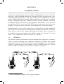
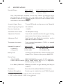
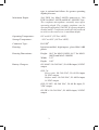
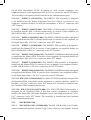
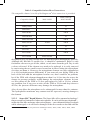
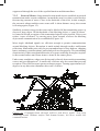
1
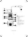
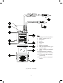
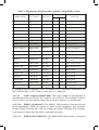
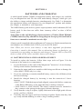
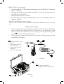
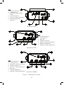
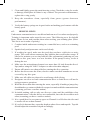
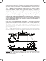
MAGNACOM
SINGLE-SIDEBAND, ACOUSTIC
DIVER TRANSCEIVERS
(MILITARY)
“Technology in Depth”
®
- NOTICE This manual and the information contained herein are provided for use as a maintenance and operation guide. No license or rights to manufacture, produce, and/
or sell either the manual or articles described herein are given. Undersea Systems
International, Inc., dba Ocean Technology Systems hereinafter referred to as
OTS, reserves the right to change specifications without notice. We recommend
that all users read and fully understand this manual before using a Magnacom®
transceiver.
All statements, technical information, and recommendations herein are based on
tests we believe to be reliable, but the accuracy or completeness thereof is not guaranteed; and the following is made in lieu of all warranties, expressed or implied,
including the implied warranties of merchantability and fitness for purpose: Seller’s
and Manufacturer’s only obligation shall be to replace such quantity of the product
proved to be defective. Before using, the user shall determine the suitability of the
product for intended use, and the user assumes all risk and liability whatsoever in
connection therewith. Neither Seller nor Manufacturer shall be liable either in tort
or in contract for any loss or damage—direct, incidental, or consequential—arising
from the use of or the inability to use the product. No statement or recommendation not contained herein shall have any force or effect unless it is in an agreement
signed by officers of the Seller and Manufacturer.
- IMPORTANT SAFETY NOTICE (Please read before using product.)
It is absolutely essential that all divers are properly trained and equipped
and fully understand this user’s manual before attempting to use a Magnacom® transceiver.
While the Magnacom® transceivers provides divers with good underwater communications, it does not change or eliminate the potential hazards of diving!
Refer to the Library page of our Web site, www.otscomm.com, for a list of
any changes made to this manual since its publication.
© Copyright 2008, 2011 by Undersea Systems International, Inc., dba
Ocean Technology Systems. All rights reserved.
Specifications are subject to change without prior notice.
i
506108-000 rev.G
TABLE OF CONTENTS
Section 1: Introduction ................................................................................1
1.1General..........................................................................................1
1.2 Specifications................................................................................2
Section 2: Equipment Description ..............................................................4
2.1 General Description......................................................................4
2.2 Package Design............................................................................. 4
2.3 Transceiver Adjustments...............................................................4
2.4 Voice-Operated Transmitter (VOX or VX)................................... 8
2.5 Push-to-Talk Switch (PTT)...........................................................8
2.6 Squelch (SQ).................................................................................8
2.7 Side Audio Volume (ST)...............................................................8
2.8 Intercom Audio (IV) (MAG-1004HS Only).................................8
2.9 Receiver Volume (RV).................................................................. 9
2.10 Dual Channel Selection.................................................................9
2.11 Related Components.....................................................................9
2.11.1 Dual Transducer (MAG-1002D)......................................9
2.11.2 Earphone-Microphone (EM) Assemblies....................... 10
2.11.2.1 EMA-2 (911060-001).....................................10
2.11.2.2 EMA-2SM (911060-098)...............................10
2.11.2.3 EMX-2 (911060-008).....................................10
2.11.2.4 EMX-2B (911060-026)..................................10
2.11.2.5 EMO-2 (900096-686)....................................10
2.11.2.6 EMH2-1 (911060-009)...................................10
2.11.2.7 EMH2-1SM (911060-100)............................. 10
2.11.2.8 EMS-2 (911060-017)..................................... 11
2.11.2.9 LAR V Adapter (900282-000)....................... 11
2.11.2.10EMD-2 (911060-067)..................................... 11
2.11.2.11 EMD-2SM (911060-101)...............................12
2.11.2.12EMDG-2 (911060-076)..................................12
2.11.2.13EMH1-1 (900332-000).................................. 12
2.11.2.14EMH1-1SM (900332-001).............................12
2.11.2.15EMMT-1 (911060-090)..................................12
2.11.2.16EMMT-1SM (911060-102)............................12
2.11.2.17EMMT-2 (911060-091)..................................12
2.11.2.18EMMT-2SM (911060-103)............................12
2.11.2.19 EM-OTS-2 (910369-000)...............................12
2.11.2.20 EM-OTS-2SM (910379-000) ........................12
2.12Microphones...............................................................................12
2.12.1 ME-16R Hot-Mic® (912086-000)..................................12
2.12.2 Super Mic® Depth Master..............................................13
2.13 Compatible Surface/Diver Transceivers.....................................14
Section 3: Adjustment and Operating Instructions ................................15
3.1General........................................................................................15
ii
3.2 Inspection of Equipment.............................................................15
3.3Magnacom® Operating Procedures.............................................15
3.4Adjustments................................................................................ 16
3.4.1 Push-to-Talk (PTT) Button............................................. 16
3.4.2 Transmit VOX or PTT....................................................17
3.4.2.1 VOX Adjustment............................................17
3.4.3 Morse Code Mode (MAG-1002D Only)........................17
3.4.4Channels......................................................................... 17
3.4.5 Squelch Adjustment........................................................ 17
3.4.6 Volume Adjustment........................................................ 18
3.5 Rebreather Installation................................................................18
3.5.1 Transceiver Installation.................................................. 18
3.5.2 Transducer Installation (MAG-1002D Only).................19
3.5.3 Rebreather Adapter Installation......................................19
3.6 Pre-Dive Checklist......................................................................19
3.7 Receiving a Message...................................................................20
3.8 Doffing the Diver Units.............................................................. 20
3.9 Examples of Underwater Communication..................................20
3.9.1 Calls Between Surface, Subs, or Divers.........................20
3.9.2 Calls Between Divers and Surface, Subs, or Bells.........21
3.9.3 Calls Between Surface Units, Subs, and Bells...............21
Section 4: Batteries and Charging ............................................................22
4.1 Battery Installation or Replacement............................................22
4.2 Battery Charging.........................................................................23
Section 5: Advanced User Information ....................................................25
5.1General........................................................................................25
5.2VOX............................................................................................25
5.3 Squelch........................................................................................28
Section 6: Maintenance and Helpful Hints ..............................................29
6.1General........................................................................................29
6.2 Periodic Maintenance..................................................................29
6.3 Helpful Hints...............................................................................30
Section 7: Basics of Sound in Water .........................................................31
7.1Background.................................................................................31
7.2 Factors That Affect Sound in Water............................................31
7.2.1Distance..........................................................................32
7.2.2 Water Density.................................................................32
7.2.3 Water Temperature.........................................................33
7.2.4 Background Noise..........................................................33
7.2.5 Zones of Silence.............................................................34
Limited Warranty ......................................................................................36
iii
SECTION 1
INTRODUCTION
Congratulations! You have just purchased one of the finest, state-of-the-art, patented
underwater communication systems available. The Magnacom® series are 70-watt,
ultrasonic, single-sideband transceivers designed to allow through-water voice
communications among divers and users on the surface. Magnacom® employs
advanced Digital Signal Processing (DSP) techniques, which ensure the highest
quality intelligibility possible. Standard features include automatic electronic
switching between VOX and PTT, dual earphones with holders1, voice-operated
transmission (VOX) or Push-to-Talk (PTT) mode, dual channels, a heavy-duty
housing, 70 watts of power, and more! In all, Magnacom® is second to none!
The Magnacom® series of diver transceivers is designed for use with virtually all
full-face masks and rebreathers with appropriate earphone-microphone assemblies.
The interface used for the earphone-microphone assembly can be designed to
fit virtually any style rebreather and/or full-face mask. See Section 2.11.2 and
Table 1 for compatibility. Special requests are welcome.
1.1GENERAL
This manual contains information about the Magnacom® underwater communication systems, including most earphone-microphone assemblies and support
equipment. Section 1 discusses the functions of the Magnacom® and provides
a table of specifications. As an example, a MAG-1004HS transceiver with an
EMA-2 earphone-microphone assembly is illustrated in Figure 1.
Figure 1
1. Some configurations employ only a single earphone.
1
1.2SPECIFICATIONS
Nominal Range:
MAG-1002D
200m to 3000m
MAG-1003D & MAG-1004HS
200m to 3000m
Note: Environmental variability such as that caused by biological noise
and interference, thermoclines, etc., can reduce range. The MAG-1002D’s
transducers must be at a minimum depth of 6 feet to avoid cavitation, wave
cancellation, and reduced range.
Acoustic Output Power:
70 watts PEP (peak envelope power) on Channel A
Audio Frequency Response: 300–4000 Hz
Receiver Sensitivity:
–110 dBv
Automatic Gain Control:
120 dB dynamic range
Adjustment Controls:
2-turn level controls located on the upper housing
(must remove lower battery compartment)
Adjustment Tool:
Small jeweler-type, flathead screwdriver used to
adjust the 2-turn level controls
Transmitter Activation:
Voice-operated transmitter (VOX) or manual
activation (PTT)
Standard Frequencies1:
• Channel A:
• Channel B:
Battery Life:
MAG-1002D
8.0875 KHz USB2
11 KHz LSB
MAG-1003D & MAG-1004HS
28.5 KHz LSB
32.768 KHz USB
Assuming 10% transmit time: 4 hours on high-power
channel (A) or 8 hours on low-power channel (B)
Battery Type:
• MAG-1002D:
RBL-20B NiMH battery pack, 12 V, 3 amp-hours
• MAG-1003D/1004HS: RB-14 NiMH battery pack, 12 V, 2 amp-hours.
Includes spring contact pad.
Low-Battery Indication: Blinking red LED on upper housing and beep in
earphone
Transducer:
Piezoelectric Broadband Helmholtz Resonator
Earphone/Microphone:
Ceramic type is standard on most FFMs. Dynamic
1. Custom frequencies may be ordered; contact OTS for details.
2. “USB” is upper sideband. “LSB” is lower sideband.
2
type is optional and allows for greater operating
depths/pressures.
Maximum Depth:
500 FSW for MAG-1002D transceiver, 300
FSW for MAG-1003D and MAG-1004HS. Note:
The earphone-microphone assembly may affect
operating depth. The ceramic earphone can be
operated to a depth of 150 FSW. If a greater depth is
needed, an EP-1 earphone can be specially ordered
to achieve the transceiver’s maximum depth.
Operating Temperature:
0°C to 60°C (32°F to 140°F)
Storage Temperature:
–10°C to 60°C (14°F to 140°F)
Connector Type:
Hi-USE®
Housing:
Injection-molded, high-impact, glass-filled ABS
plastic
Housing Dimensions:
Height: 10.0” for MAG-1002D, 8.63” for MAG1003D and MAG-1004HS
Width: 3.55”
Depth: 1.80”
Battery Chargers:
RC-MAG2: 90–260 VAC, 50–60 Hz input; 24 VDC
output
RCL-7A:
Diver units: 90–260 VAC, 50–60 Hz input;
24 VDC output
Surface units: 90–260 VAC, 50–60 Hz input;
16 VDC output
RCS-3U-HIU: 90–260 VAC, 50–60 Hz input; 21
VDC output
RC-SW-6: 90–260 VAC, 50–60 Hz input; 24 VDC
output
3
SECTION 2
EQUIPMENT DESCRIPTION
2.1
GENERAL DESCRIPTION
The Magnacom® diver transceivers are housed in a watertight enclosure designed
for easy belt or tank mounting. For surface operation, our Magnacom® MAG1001S is fully compatible with the diver transceivers and provides long-range
performance. Other compatible surface transceivers are discussed in Section
2.13. Be sure to obtain a surface transceiver that is programmed to operate on
at least one of the same channels as the Magnacom.
2.2
PACKAGE DESIGN
The Magnacom® housing is constructed of high-impact, glass-reinforced ABS
plastic, which will not corrode if scratched.
The housing is divided into two major parts (Figure 2): the upper electronics and
the lower battery sections. An o-ring between the sections serves to maintain
the housing’s watertight integrity. Stainless steel latches maintain a constant
pressure that preloads the o-ring and prevents leakage within specified depths.
(Note: Upper and lower housings are a matched set; do not mix them up with
those of other transceivers.)
2.3
TRANSCEIVER ADJUSTMENTS
The Magnacom® transceivers provide adjustment controls for squelch (SQ), voiceoperated transmitter (VOX or VX) sensitivity, receive volume (RV), side audio
(ST), channel selection, and—on the MAG-1004HS only—intercom volume (IV).
Most adjustments are made on the surface, not while diving. There are two options
for transmission: VOX (voice activation) and push-to-talk (PTT); the MAG-1002D
also provides a third option, Morse code mode. The sensitivity control for the VOX
is a two-turn level control located on the bottom of the upper electronics housing
(Figure 7, Section 5). This adjustment must be made in a dry environment.
To switch from VOX to PTT or vice versa, simply depress the PTT button three
times within 2 seconds. You will hear a double two-tone beep indicating VOX or
a single two-tone beep indicating the PTT mode. With the MAG-1002D, holding
down the PTT button on the third press switches the unit into Morse code mode,
indicated by four tones, long-short-long-short.
The switch for channel selection and all two-turn adjustments for VOX sensitivity,
squelch sensitivity, side audio volume, and intercom volume (MAG-1004HS
only) are located on the bottom of the upper electronics module. To access these
adjustments, remove the lower battery housing and locate the controls on the bottom
of the electronics module (Figure 7, Section 5). Adjustments will be discussed fully
4
Key
1. To ear-mic assembly
2.Strike
3. Connector for battery
4. Large o-ring (p/n 283002-000)
5.Latch
6. Battery housing
7. RBL-20B NiMH battery (p/n 912087-002)
8. Belt clip
9. Upper electronics module
10.Connector for dual transducer
11.Water switch (1 of 2)
(A) MAG-1002D
Figure 2: Magnacom® components
5
Key
1. High-powered transducer
2. Water switch (1 of 2)
3. Red LED
4.Strike
5. Belt clip
6.Latch
7. Battery housing
8. RB-14 NiMH battery (p/n
910272-000)
9. Large o-ring (p/n 283002000)
10.Spring battery contacts
11.Upper electronics module
12.To ear-mic and charging
connection
(B) MAG-1003D
6
Key
1. High-powered transducer
2. Water switch (1 of 2)
3. Red LED
4.Strike
5. Belt clip
6.Latch
7. Battery housing
8. RB-14 NiMH battery (p/n
910272-000)
9. Large o-ring (p/n 283002000)
10.Spring battery contacts
11.Upper electronics module
12.To ear-mic and charging
connection
13.Diver-to-diver communication
(C) MAG-1004HS
7
in Section 5, Advanced User Information.
2.4 VOICE-OPERATED TRANSMITTER (VOX OR VX)
VOX operation provides hands-free communications. The user simply talks for
the unit to transmit automatically. The VOX sensitivity needs to be set according
to the diver’s voice. If the VOX is not adjusted properly, false transmission or
inability to transmit may occur. If the user is in the VOX mode, he can override
it by using the PTT control. Overriding the VOX mode via the PTT switch
automatically switches the transceiver to the PTT mode. Tests have shown that
most divers favor the PTT mode over the VOX mode.
2.5 PUSH-TO-TALK SWITCH (PTT)
A unique feature of the Magnacom® diver transceivers is their ability to be switched
electronically between the VOX and PTT modes while underwater, not only on
the surface. The location of the PTT button varies among earphone-microphone
assemblies, because of the many different configurations of full-face masks and
rebreather mouthpieces. When in the PTT mode, the user simply presses the
button to transmit. The system automatically returns to the receive mode upon
release of the PTT button. The PTT function overrides the VOX function. The
PTT button is also used to switch the transceiver from VOX to PTT or vice
versa and, with the MAG-1002D, to enter and exit Morse code mode. Refer to
Section 3.4.1 for further instructions.
2.6
SQUELCH (SQ)
The squelch provides a means to limit the background noise heard by the diver. The
proper setting depends on the specific requirements of the dive. For most operations
a setting of one half turn counterclockwise from fully clockwise is optimum. If
long range is desired, use minimal or no squelch. (Note: The MAG-1002D with
standard frequencies has minimal squelch, to ensure maximum range at all times.)
We recommend the use of an increased setting for most SDV training operations or
when one is working close-range to other divers and/or the surface station.
2.7
SIDE AUDIO VOLUME (ST)
When you transmit, you will hear yourself via your earphone. This is called “Side
Audio” (“Sidetone,” ST). It is useful for verifying that you are transmitting. Some
full-face masks or helmets may have a configuration that causes feedback between
the microphone and earphones. If this occurs, a lower ST setting is required. Refer
to Section 3.4.6 (Volume Adjustment) for more information.
2.8
INTERCOM AUDIO (IV) (MAG-1004HS ONLY)
Your secure diver-to-diver intercom volume is on all the time and allows you to
hear yourself and any other diver that plugs in his coiled cord. The two-turn level
8
control on the bottom of the electronics module allows adjustment of the intercom
audio volume. A clockwise turn increases the volume, which typically should be
set slightly lower than the other volume settings.
If the MAG-1004HS will be used in through-water mode only, turn down the
intercom volume to reduce or eliminate the continuous diver breathing noise for
clearer communications.
2.9
RECEIVER VOLUME (RV)
The volume control for all audio signals received through wireless transmission is
called “Receiver Volume” (RV). Each diver hears a little differently and may prefer
a loud or soft listening volume. A clockwise turn increases the volume.
2.10
DUAL CHANNEL SELECTION
The Magnacom® diver transceivers have the capability to operate on two different
frequencies. We refer to these as channels. The ability to select between channels
is a feature useful for dive teams who have more than one group. The diver can
select channels only on the surface (not while diving). The channel-select switch
is located on the bottom of the upper electronics transceiver and is labeled A and
B. Refer to Section 3.4.4 (Channels) for more information.
The peak output of a transducer ranges over a narrow band of frequencies, so one
channel is more efficient than the other. With the MAG-1003D and MAG-1004HS,
the transducer output has been optimized for Channel A, so it is more efficient
and will provide a longer range than B. With the MAG-1002D, the difference is
negligible because of the low frequency levels.
IMPORTANT NOTE: Ensure all the transceivers are on the same channel before
beginning a dive.
2.11
RELATED COMPONENTS
2.11.1 DUAL TRANSDUCER (MAG-1002D): The standard transducer (Figure
3) is a dual co-phased assembly. It is designed to be installed over the LAR V
Figure 3
9
rebreather’s oxygen tank. (Other dual transducer configurations are possible via
special order.) The dual design ensures the diver’s signal is rarely “shadowed” by
his suit or equipment.
2.11.2 EARPHONE-MICROPHONE (EM) ASSEMBLIES: Because each
full-face mask manufacturer has designed a different communication port for
its masks, we have provided different earphone-microphone (EM) assemblies.
Table 1 is a compatibility chart with many of the EM assemblies available for the
Magnacom® diver transceivers. Note: If you have a diving helmet or FFM that is
not on the compatibility chart, contact OTS or your local OTS dealer to find out if
it is available or for a quote to build a custom EM assembly.
2.11.2.1
EMA-2 (911060-001): The EMA-2 EM assembly is designed for all
Divator MK II “AGA” full-face masks (FFMs). It has dual ceramic earphones with
earphone holders, an ME-16R Hot-Mic®, a Hi-Use® connector, and a PTT button.
The assembly is installed into the Divator MK II FFM communication port.
2.11.2.2
EMA-2SM (911060-098): The EMA-2SM EM assembly is designed for
all Divator MK II “AGA” FFMs. It consists of dual ceramic earphones, two earphone
holders, the Super Mic® (all-depth, floodable, noise-cancelling microphone), a
Hi-Use® connector, and a PTT button. The assembly is designed to install into the
Divator MK II FFM communication port.
2.11.2.3
EMX-2 (911060-008): The EMX-2 EM assembly is designed for the
EXO-26 original FFM. It consists of two dynamic earphones, an ME-16R Hot-Mic,
a Hi-Use® connector, and a PTT assembly.
2.11.2.4
EMX-2B (911060-026): The EMX-2B EM assembly is designed for the
EXO-26 standard FFM. It is similar to the EMX-2 but fits the balanced-regulator
version of the EXO-26 with an oral-nasal cavity.
2.11.2.5 EMO-2 (900096-686): The EMO-2 EM assembly is designed to
install into the Ocean Reef Neptune NIRA FFM. It consists of two earphones, two
earphone holders, an ME-16R Hot-Mic, a Hi-Use® connector, and a PTT button.
It installs into a port located on the side of the FFM.
2.11.2.6 EMH2-1 (911060-009): The EMH-1 EM assembly is designed to
operate with the HM-2 mouth mask. It consists of an HM-2 mouth mask, a head
strap, a ceramic earphone, an ME-16R Hot-Mic, a Hi-Use® connector, and a PTT
button (located on the HM-2).
2.11.2.7
EMH2-1SM (911060-100): The EMH-1SM EM assembly is designed
to operate with the HM-2 mouth mask. It consists of an HM-2 mouth mask, a head
strap, a ceramic earphone, an all-depth Super Mic, a Hi-Use® connector, and a PTT
button (on the HM-2).
2.11.2.8
EMS-2 (911060-017): The EMS-2 is an EM assembly designed to
10
Table 1: Magnacom® Earphone-Microphone Compatibility Chart
Model Number
Part Number
Microphone
EMA-2
911060-001
Hot-Mic®
EMA-2SM
911060-098
EMX-2
Earphone
Single
Dual
Mask Type
X
All Divator MK II FFMs
Super Mic
X
All Divator MK II FFMs
911060-008
Hot-Mic
X
EXO-26 original FFM
EMX-2B
911060-026
Hot-Mic
X
EXO-26 standard FFM
EMO-2
900096-686
Hot-Mic
X
Ocean Reef FFM
EMH2-1
911060-009
Hot-Mic
EMH2-1SM
911060-100
Super Mic
EMS-2
911060-017
Hot-Mic
LAR V Adapter
900282-000
Dynamic
mic
EMD-2
911060-067
Hot-Mic®
X
M-48 SuperMask® FFM
EMD-2SM
911060-101
Super Mic®
X
M-48 SuperMask® FFM
EMDG-2
911060-076
ME-500
X
Dräger Panorama Nova
Dive Mask
EMH1-1
900332-000
Hot-Mic®
X
HM-1 mouth mask
EMH1-1SM
900332-001
Super Mic®
X
HM-1 mouth mask
EMMT-1
911060-090
Hot-Mic®
X
Mantis FFM
EMMT-1SM
911060-102
Super Mic®
X
Mantis FFM
EMMT-2
911060-091
Hot-Mic®
X
Mantis FFM
EMMT-2SM
911060-103
Super Mic®
X
Mantis FFM
EM-OTS-2
910369-000
Hot Mic®
X
Guardian FFM
EM-OTS-2SM
910379-000
Super Mic®
X
Guardian FFM
®
®
®
®
®
®
X
HM-2 mouth mask
X
HM-2 mouth mask
X
®
X
ScubaPro FFM
LAR V mouthpiece
be installed into the ScubaPro FFM. It consists of two earphones and holders, an
ME-16R Hot-Mic, a PTT control, and a Hi-Use® connector.
2.11.2.9
LAR V Adapter (900282-000): The LAR V Adapter is placed between
the inhalation hose and LAR V dive surface valve (DSV)/T-bit assembly. It allows
basic words to be transmitted without the need for a full-face or mouth mask.
2.11.2.10 EMD-2 (911060-067): The EMD-2 EM assembly is designed for all
M-48 SuperMask® FFMs. It consists of dual ceramic earphones, two earphone
holders, an ME-16R Hot-Mic, a Hi-Use® connector, and a PTT button. The assembly
is designed to install into the M-48 communication port.
2.11.2.11
EMD-2SM (911060-101): The EMD-2SM EM assembly is designed
11
for all M-48 SuperMask® FFMs. It consists of dual ceramic earphones, two
earphone holders, an all-depth Super Mic, a Hi-Use® connector, and a PTT button.
The assembly is designed to install into the M-48 communication port.
2.11.2.12 EMDG-2 (911060-076): The EMDG-2 EM assembly is designed
to be installed into the Dräger Panorama Nova Dive Mask. It consists of two
earphones, earphone holders, an ME-500 microphone, a Hi-Use® connector, and
a PTT button.
2.11.2.13 EMH1-1 (900332-000): The EMH1-1 EM assembly is designed to
be installed into the HM-1 silicone mouth mask. It consists of one earphone, an
ME-16R Hot-Mic, a Hi-Use® connector, and a PTT button.
2.11.2.14 EMH1-1SM (900332-001): The EMH1-1SM EM assembly is designed
to be installed into the HM-1 silicone mouth mask. It consists of one earphone, an
all-depth Super Mic, a Hi-Use® connector, and a PTT button.
2.11.2.15 EMMT-1 (911060-090): The EMMT-1 EM assembly is designed to
install into the Mantis FFM. It consists of one earphone, an earphone holder, an
ME-16R Hot-Mic, a Hi-Use® connector, and a PTT button.
2.11.2.16 EMMT-1SM (911060-102): The EMMT-1SM EM assembly is designed
to install into the Mantis FFM. It consists of one earphone, an earphone holder, an
all-depth Super Mic, a Hi-Use® connector, and a PTT button.
2.11.2.17 EMMT-2 (911060-091): The EMMT-2 EM assembly is designed to
install into the Mantis FFM. It consists of two earphones, two earphone holders,
an ME-16R Hot-Mic®, a Hi-Use® connector, and a PTT button.
2.11.2.18 EMMT-2SM (911060-103): The EMMT-2SM EM assembly is designed
to install into the Mantis FFM. It consists of two earphones, two earphone holders,
an all-depth Super Mic, a Hi-Use® connector, and a PTT button.
2.11.2.19 EM-OTS-2 (910369-000): The EM-OTS-2 EM assembly is designed for
all Guardian FFMs. It has dual ceramic earphones w/ earphone holders, an ME-16
Hot-Mic, a Hi-Use® connector, and a PTT button. The assembly is installed into
the Guardian FFM communications port.
2.11.2.20 EM-OTS-2SM (910379-000): The EM-OTS-2SM EM assembly is
designed for all Guardian FFMs. It has dual ceramic earphones w/ earphone
holders, the Super-Mic (all depth, floodable, noise-cancelling microphone), a HiUse® connector, and a PTT button. The assembly is installed into the Guardian
FFM communications port.
2.12MICROPHONES
2.12.1 ME-16R Hot-Mic® (912086-000): The ME-16R Hot-Mic is a 150-ohm,
water-resistant microphone element. It is a state-of-the art microphone element
12
Table 2: Compatible Surface/Diver Transceivers
The compatible channel (A or B) of the Magnacom® diver transceiver is provided.
Compatible Model
MAG-1002D
MAG-1003D &
MAG-1004HS
BELL-200
8-kHz version
Buddy Phone®
SSB-2010
B
B
SSB-1001B
A&B
SSB-2001B-2
B
MAG-1003-PS
A&B
MAG-1001S
A&B
A & B
SP-100
B
STX-101
B
STX-101M
STX-101SB
A&B
8-kHz version
designed to give you long, trouble-free use and the highest intelligibility possible.
Although the Hot-Mic is trouble free, it should be maintained. Rinse it with
freshwater after use to get all dirt, debris, or salt water from the grill. Dry it with
a clean, soft towel. If the element ever needs to be replaced, it is easily removed
by unscrewing the two small screws located on its base.Getting the microphone
wet does not harm it. However, the microphone element can only withstand an
8- to 10-foot depth/pressure differential. If you removed your diving FFM at the
back of the boat and the microphone became wet, there would be no problem;
but if the FFM with element dropped more than 8 to 10 feet into the water, the
change in pressure probably would damage the microphone element. In tests
we have taken off the FFM at 30 feet and replaced it, still at 30 feet, without
any problem; but if one were to take off the FFM at 30 feet and drop down to
40 feet, the pressure difference may damage the microphone.
Also, do not allow the microphone to be submerged for more than five minutes.
The hydrophobic membrane may saturate and be squeezed, causing damage to
the element.
2.12.2 Super Mic® Depth Master: The Super Mic offers patented technology*
that overcomes a limitation of other microphones. It can be used at any depth and—
unlike the Hot-Mic and many other microphones—can withstand changes in depth
while submerged, so it will not be damaged if the diver needs to descend with the
*U.S. Patent no. 7,170,822; EU patent nos. 000458351-0001, -0002, -0003, -0004, -0005, -0006.
13
mask flooded (e.g., if the full-face mask is removed and stowed when switching
to another air system). It has a compact, lightweight design and noise-cancelling
characteristics, reducing background noises to provide clearer communications.
When only the highest quality of intelligibility is required, the Hot-Mic is the
preferred choice; however, the Super Mic’s intelligibility is sufficient for most
diving situations.
To assure clear communications when using the Super Mic, it should be no more
than 1/4 inch from the corner of the diver’s mouth.
After each dive, clean the Super Mic by rinsing it with freshwater and drying it
with a clean, soft towel. No other maintenance is required.
Note: Do not press on the microphone diaphragm; doing so may cause damage.
It is possible for the MAG-1003D or MAG-1004HS to transmit sporadically when
used with the Super Mic, especially in combination with the KMDSI M-48 SuperMask. If this problem occurs, see Section 6.3, Helpful Hint #13.
2.13
COMPATIBLE SURFACE/DIVER TRANSCEIVERS
The Magnacom® transceivers can transmit to and receive from other Magnacom®
transceivers as well as the Magnacom® MAG-1001S surface unit when on the same
frequency and within range. Other compatible transceivers are listed in Table 2.
14
SECTION 3
ADJUSTMENT AND OPERATING INSTRUCTIONS
3.1GENERAL
This section contains information for operating Magnacom® through-water
transceivers.
3.2
INSPECTION OF EQUIPMENT
Upon arrival of the equipment, inspect the shipping container for dents, gouges,
or any other evidence of rough handling.
The Magnacom® transceiver should be visually inspected upon removal from
the shipping container. If any damage is evident, immediately file a claim with
the carrier. Forward a copy of the damage claim to OTS, see page 36 for contact
information. Arrangements for repair or replacement will then be made.
NOTE: Although the Magnacom is rugged in design, care should be exercised
to ensure that problems are not caused by improper handling. Store the unit
in a safe, secure area after unpacking.
3.3
MAGNACOM OPERATING PROCEDURES
STEP 1: Ensure the batteries are charged and all o-rings are free of debris and in
good condition.
STEP 2 (MAG-1002D only): Ensure the transducer cable is securely connected
to the dual transducer.
STEP 3: Ensure all internal settings are properly adjusted (squelch, VOX, channel,
etc.). See Section 3.4 (Adjustments).
STEP 4: Verify the battery connector wires have not been pinched while securing
the upper and lower housings (a pinched wire will cause flooding, which may
damage the unit).
STEP 5: Connect together the Hi-Use® connectors of the Magnacom® transceiver
and the FFM or LAR V Adapter.
STEP 6: Immerse the diver unit in a pail of water. If testing between 2 units, place
each in a separate pail of water. Separate the pails to a distance of approx. 6 feet.
When immersed, verify the red LED is illuminated—indicating power is activated.
(If unit is a MAG-1002D, it is only necessary to submerge the xducer assembly.)
To activate the unit, use a paper clip, bent over and in contact with both water
activation screws.
15
WARNING: Minimal operation through-air is possible, but not recommended.
Conditions may arise where transmitter amplification can occur and cause
permanent damage to the unit(s).
STEP 7: Ensure they are on the same channel. Using the FFM microphone while
the unit is still activated, press the PTT button and talk into the microphone. You
should hear yourself through the other diver unit or the surface station. (Note: The
range in air is approximately 20 feet.) If using the system in the voice activation
mode (VOX), speak loudly with a vowel sound such as “AH” or say the number
“FOUR” to trigger the VOX. (Note: A Magnacom® transceiver, when first initiated,
will always begin in the PTT mode, even if you had it in the VOX mode when it
powered down.)
STEP 8: Verify your transceiver is on the same channel everyone else will be using,
earphone levels are to your liking, the VOX setting is proper (unless you plan on
using only PTT), and the squelch setting is appropriate for the environment and
range you require (refer to Section 3.4, Adjustments, for assistance if necessary.)
Note: The factory squelch default setting should be appropriate for most operations.
Although earphone volume may be too high on the surface, it will be at the proper
level during a dive.
STEP 9: Repeat the above procedures with any other transceiver, and verify that
it is operational and on the same channel.
STEP 10: After you have verified all transceivers are on the same channel, all
settings are as desired, the batteries are fully charged, and the o-ring was installed
properly and is clean of debris, you are ready to dive.
NOTE:
(1) The received communications will not sound as clear during these tests
as they will in open water.
(2) The units will always start in PTT mode after powering down or up.
(3) The VOX setting typically increases in sensitivity when the mask is under
pressure.
3.4ADJUSTMENTS
The Magnacom® transceivers have a unique feature that allows you to change the
transmission mode electronically, either out of the water or in the water. If you depress
the PTT button three times within two seconds, you will hear in your earphones
either a two-tone beep sequence or a short beep. A two-tone beep sequence indicates
the unit is going into VOX mode. A single tone indicates the system is going into
PTT mode. (Note: The system requires three distinct presses. If the three presses
are done too quickly—i.e., three times within 1 second or less—then the system
may not switch modes.)
16
3.4.1 Push-to-Talk (PTT) Button: The PTT button serves two purposes:
(1) When pressed and held, you activate the transmitter. As long as you hold the
PTT button, you will be transmitting. When you release the button, your transceiver
will automatically return to the receive mode. If you are in the VOX mode, you
can still depress the PTT to override the VOX. This is useful if your VOX is not
adjusted properly and you have trouble activating the VOX. However, if you
override the VOX, when you release the PTT button, you will still have the VOX
delay (see Section 3.4.2.1, VOX Adjustment). (2) The PTT button is also used to
change communication modes. When you click it three times within two seconds,
the unit switches from VOX to PTT mode.
With the MAG-1002D, the PTT button serves a third purpose: Pressing it three
times while holding the third depression causes the transceiver to enter Morse code
mode; to exit this mode, hold the button down and listen for three short beeps.
3.4.2 Transmit VOX or PTT: When power is first applied, the system
defaults to PTT mode. By pressing the PTT button three times within two seconds,
the system toggles between VOX and PTT modes and emits a verification tone. A
two-tone sequence indicates VOX mode, and a short tone indicates PTT mode.
3.4.2.1
VOX Adjustment: A two-turn level control for adjusting the VOX
sensitivity is located on the bottom of the electronics housing. The factory default
is a one half to middle setting, which is one full clockwise rotation. The control is a
two-turn device with its mid setting at one full revolution from fully counterclockwise
or clockwise. Rotating clockwise increases VOX sensitivity. A rotation of one
eighth is recommended for fine adjustments of either more or less sensitivity. The
factory setting is usually sufficient for most voices. Remember to speak close to
the microphone (less than 1/4”) at higher than normal volume.
3.4.3 Morse Code Mode (MAG-1002D Only): You can switch from
voice mode to Morse code mode by triple-pressing the PTT switch and holding
the button down for the third depression. Continue holding it down until you hear
a code response, Dah Dit Dah Dit. When the transceiver is in Morse code mode,
you can send a coded message by using the PTT as a code key. To return to voice
mode, press and hold the PTT button until you hear three short beeps.
3.4.4Channels: To change between channels A and B, open the housing,
find the two-position rotary (MAG-1002D) or slide switch located on the electronics
module, and place the switch in the desired position. Note: With the MAG-1003D
and MAG-1004HS, Channel A is more efficient for long-range communication; with
the MAG-1002D, the efficiency of the two channels is approximately equal.
3.4.5 Squelch Adjustment: Open the housing and locate the squelch
control. A fully counterclockwise position disables the squelch. This setting is
recommended when it is critical that all communications are received. It ensures
reception of all signals, even those buried in background noise. Signals so weak
that they are marginally detectable will never unsquelch a unit. For very long-range
17
communication, the squelch control must be set fully counterclockwise.
If the system is operated at close range and this range will never be increased, a
setting of one-and-a-half turns clockwise is good for close-quarter environments
(e.g., SDV training operations).
3.4.6 Volume Adjustment: Receive (RV), side audio (ST), and intercom
(IV) (MAG-1004HS only) volume adjustments are made inside the electronics
module. See Figure 7 (in Section 5).
3.5
REBREATHER INSTALLATION
This section provides instructions for installation of the Magnacom® diver units into
a rebreather system. These instructions apply specifically to the LAR V but can be
adapted for different rebreathers. Refer to Figure 4 throughout this section.
3.5.1 Transceiver Installation: Examine the user’s equipment
configuration to determine the best location to install and method to secure the
transceiver. The type of diving activity and the location of other divers should also
be considered for where to install the transceiver to avoid body shadowing and
other acoustic obstructions (see Section 7, Basics of Sound in Water); for example,
the diver should never carry the transceiver between his body and BCD bladder,
because doing so would subdue the acoustic signal.
If a LAR V is being used, the transceiver can be mounted to the LAR V housing
with straps (not supplied). Figure 4 shows the transceiver mounted to the LAR V
fiberglass shell.
3.5.2
Transducer Installation (MAG-1002D Only): The dual
Key
1. LAR V adapter
4. Magnacom® transceiver
2. DSV/T-bit assembly 5. Retaining strap
3. Rebreather hose
Figure 4: Setup of Magnacom® system with a LAR V rebreather
18
transducer is installed on top of the oxygen bottle via standard LAR V retaining
straps. The straps are passed through slots in the transducer assembly before being
stretched around the oxygen bottle and finally affixed to the fiberglass shell.
3.5.3 Rebreather Adapter Installation: If you use a rebreather
adapter (e.g., the LAR V adapter) instead of a full-face or half mask, place the
adapter between the dive surface valve (DSV)/T-bit assembly and the inhalation
hose.
3.6
l.
PRE-DIVE CHECKLIST
Fully charged NiMH battery pack installed (see Section 4).
2. O-rings in place, clamps secure.
3. Diver transceiver in place, with the transducer free of diving equipment
obstructions.
4. Earphone(s) adjusted and in position.
5.Hi-Use® connector lightly greased and properly mated.
6. Microphone is tightly secured by screws to the bushings on the nickel wires
(ME-16R Hot-Mic only).
7. Diver is dressed out so cables will not snag and the transducer is not covered
by any diving equipment.
8. In-water surface check:
a. Recheck the location of the earphone(s).
b. Submerge the transducer (the waterline should be at the diver’s chest
level).
c. Establish communication.
d. Your dive partner’s equipment is properly adjusted, and cables are dressed
so as not to snag.
NOTE:
Your speech should be considerably slower than normal, and each word should be
pronounced clearly and distinctly. Speak one word at a time instead of in flowing
sentences. Do not shout, but use slightly loud conversation volume. Minimize
exhalation while speaking. Your communication will be more easily understood
if you are relaxed, since speech is less intelligible when a diver is anxious.
You should conduct a pool checkout and have more pool practice before using
the system in open water. While Magnacom® transceivers provide divers with
good underwater communications, they do not change or eliminate the potential
19
hazards of diving!
CAUTION: Use any standard safe entry into the water, but be aware of the
additional equipment you are wearing. The transceiver and cables should be
positioned so they do not snag or hit against anything during entry. Keep a copy
of this checklist handy for reference before entering the water.
3.7
RECEIVING A MESSAGE
When receiving a transmission:
• Relax.
• Concentrate on hearing.
• Try different earphone positions until the best one is found.
• Minimize exhalation bubble noise, but do not hold your breath. Most divers find
that an inhalation cycle is the best time to receive a message. While exhaling,
bubble noise makes hearing difficult (with open-circuit scuba).
3.8
DOFFING THE DIVER UNITS
1. Disconnect the Hi-Use® connector from the full-face mask, HM-2 mouth mask,
or rebreather adapter. If you are using a rebreather, doff it.
2. As soon as possible after each dive, rinse the unit in freshwater to remove salt
and other mineral deposits.
3. Although the Magnacom® transceivers are ruggedly constructed for long
life in the marine environment, we strongly recommend that you place your
transceiver in a protective carrying case between dives and take special care
to avoid damaging the transducer.
3.9
EXAMPLES OF UNDERWATER COMMUNICATION
3.9.1 CALLS BETWEEN SURFACE, SUBS, OR DIVERS: Listen for a
break in conversation if others are communicating in the area. Identify whom
you are calling and then identify yourself. Continue speaking until the message is
complete. At the end of each message, say “OVER” if a response is required and
“OUT” if no response is required.
If using the LAR V Adapter, a limited lexicon should be used and practiced
among all team members. Speech intelligibility among trained talkers averages
around 40%, as verified through word list tests.
EXAMPLE (not using limited lexicon):
DIVER A: Red Diver, this is Blue Diver. Do you see the wreck yet? . . .
OVER.
20
DIVER B: Blue Diver, this is Red Diver. Yes, I see the wreck, it’s ten yards to
your right. . . . OUT.
3.9.2
CALLS BETWEEN DIVERS AND SURFACE, SUBS, OR BELLS:
EXAMPLES:
DIVER A: Topside, this is Blue Diver. How far am I from the dive boat? . . .
OVER.
SURFACE: Blue Diver, this is Topside. I see your bubbles 50 feet off my port
bow. . . . OUT.
DIVER A: Sub, this is Blue Diver. How long before I must lock in? . . .
OVER.
SUB B:
Blue Diver, this is Sub. We expect you in seven minutes. . . . OUT.
3.9.3 CALLS BETWEEN SURFACE UNITS, SUBS, AND BELLS: Surface
units within range can communicate in open water or harbors, thereby avoiding
the sometimes crowded and less private channels. Crews of submarines or bells
can communicate with one another or with surface units in much the same
way. We recommend that standard radio/telephone procedures be used in all
communications.
- IMPORTANT SAFETY NOTES It is absolutely essential for all divers to be properly trained and equipped before
responding to distress, emergency, and safety calls.
WARNING: Under no circumstances should a diver begin an ascent while holding
his breath (air embolism may occur).
21
SECTION 4
BATTERIES AND CHARGING
A nickel-metal hydride (NiMH) rechargeable battery and charger are available
for your Magnacom® unit. We also offer multi-battery chargers, which give you
the ability to charge multiple batteries simultaneously. See Table 3 to determine
the appropriate battery and chargers for your Magnacom® product and whether
the charger is included or sold separately.
The NiMH battery pack delivers greater capacity than a nickel cadmium (NiCad)
battery pack. It also does not suffer from “memory effect” as does a NiCad
battery pack.
Note: Due to the self-discharge characteristics of Nickel Metal Hydride
(NiMH) batteries, they should be charged upon receipt of the unit and at
least once a month to maintain service life.
A battery pack is supplied with your Magnacom® transceiver. Replacement batteries
and chargers are available from OTS or your local OTS dealer.
Note: When you receive your battery, it may have upgraded specifications
from what is stated in this manual. Due to advancing battery technologies, we
continually are upgrading our batteries and chargers. Contact OTS or your OTS
dealer to find out the latest available battery and charger.
4.1 BATTERY INSTALLATION OR REPLACEMENT
To install or replace the batteries, follow these steps (refer to Figure 2 for the
locations of the transceiver components):
1. Locate the latches on the sides of the Magnacom® transeiver’s lower housing.
Pull up on the latches simultaneously.
2. Separate the upper and lower modules while being careful not to damage the
wires (MAG-1002D only) or o-ring.
3. If you are replacing a currently installed battery, remove the old battery from
the lower housing.
4. Install the charged battery by inserting it into the transceiver’s lower
housing.
• MAG-1002D: With their tapered ends aligned, connect the Molex® connector
of the RBL-20B battery to the upper housing’s mating connector.
• MAG-1003D or MAG-1004HS: The battery contacts must be oriented so
they connect to the springs in the upper eletronics housing.
5. Verify that the o-ring is in place, lightly lubricated with a high-grade silicone
grease, and free of debris.
6. Carefully mate the upper and lower housings together. Ensure that they line
up evenly and that nothing is on the o-ring or mating surface.
22
Table 3: Magnacom® Batteries and Chargers
Magnacom®
Product
Battery
Standard Charger
Charger Multi-Battery Charger
Included?
(not included)
MAG-1002D
RBL-20B
RC-MAG2
(part # 912087-002) (part # 900331-000)
No
RCL-7A
(part # 900307-000)
MAG-1003D
RB-14
RC-14i
(part # 910272-000) (part # 910273-000)
Yes
RC-SW-6
(part # 910291-000)
MAG-1004HS
RB-14
RC-14i
(part # 910272-000) (part # 910273-000)
Yes
RC-SW-6
(part # 910291-000)
7. Connect the latches from the lower housing to the upper strikes. Pull down the
latches simultaneously until fully down. Doing so will spring-load the upper
and lower assemblies.
8. Look on all sides of the transceiver to verify the upper and lower assemblies
appear evenly matched with no high spots. Note: If the housing is not completely
sealed, water will enter during the dive and may damage the battery.
4.2
BATTERY CHARGING
Charge the battery pack according to the instructions below, when first purchased
and when the power has depleted.
MAG-1002D:
• RC-MAG2 charger:
1. Follow Steps 1–3 of Section 4.1 to remove the battery pack from the transceiver.
2. Connect together the Molex® connectors of the RBL-20B battery pack and
the RC-MAG2 charger.
3. Connect the charger’s power input cord to the AC power source (90–264
VAC, 50–60 Hz).
4. Charge the battery for 14 hours.
5. Disconnect the power input cord from the AC power source and the battery
pack from the charger.
6. Follow Steps 4–8 of Section 4.1 to reinstall the battery pack into the transceiver.
• RCL-7A multi-battery charger:
1. Follow Steps 1–3 of Section 4.1 to remove the battery pack from the transceiver.
2. Follow the operating instructions in the user’s manual provided with the
RCL-7A.
MAG-1003D and MAG-1004HS:
23
• RCS-3U-HIU smart charger:
1. Connect the RCS-3U-HIU charger to the transceiver’s EM Hi-Use® connector
(Fig. 5, #1 and 2).
2. Connect the charger’s power input cord (Fig. 5, #4) to the AC power source
(90–260 VAC, 50–60 Hz).
3. Charge the battery for 4-6 hours.
4. Disconnect the power input cord from the AC power source and the transceiver
from the charger.
• RC-SW-6 multi-battery smart charger:
Refer to the RC-SW-6 user’s manual for operation instructions (see also Fig.
6).
- IMPORTANT NOTES 1.
When charging the battery pack for the MAG-1003D or MAG-1004HS, be
sure to connect the charger’s Hi-Use® connector to the transceiver’s EM
cable, not to its intercom coiled cord . Charging current applied through the
coiled cord will not charge the batteries.
2.
Do not charge the battery pack for more than 14 hours. Doing so may overheat
and damage the battery.
Key
1. Charger’s Hi-Use® connector
2. Non-coiled cord’s HiUse® connector
3. Coiled cord’s Hi-Use®
connector
4. AC power input plug
Figure 5
Key
1. AC power input plug
2. Charger’s Hi-Use® connectors
Figure 6
24
SECTION 5
ADVANCED USER INFORMATION
5.1GENERAL
Although the Magnacom® series is designed so that minimal manual adjustments
are necessary, special adjustments are available. These adjustments allow the user
to define sensitivities of the VOX and squelch systems, adjust listening volumes,
and change channels. Because no standards for design of full-face masks have been
established, virtually all full-face masks have different internal designs. Some
designs have little room for microphone installation, which makes it necessary
to have a more sensitive setting. These advanced adjustments offer the user more
options.
When VOX is selected, your transceiver will give you a setting that is either the
factory preset or the user’s custom setting. If you find that you need more or less
sensitivity, you can easily change the factory settings.
The adjustment controls are located on the bottom of the upper electronics module.
The controls include level controls (VOX, side audio volume, etc.) and a switch
for changing channels (Figure 7).
5.2VOX
The VOX sensitivity control is labeled “VOX” (“VX” on the MAG-1002D) on the
bottom of the electronics compartment and can be accessed by removing the lower
battery compartment. The VOX control (Figure 7) can be rotated two times before
stopping. Rotation in the clockwise direction increases the sensitivity. If a VOX
high setting is too sensitive, causing false triggering, rotate it counterclockwise until
a good setting is found (see Figures 8 through 10 for a graphic look at the effect of
rotating the adjustment control). Divers should use a low VOX setting when using
an ME-16R Hot-Mic®. The Super Mic® may require a higher VOX setting, but it
is a good idea to experiment with it before diving to determine the proper setting.
A higher setting should be used if the microphone-mask combination causes the
microphone to be farther than a quarter inch from the diver’s lips. Figures 8 through
10 illustrate the relationship between the number of turns and sensitivity. CAUTION:
Do not force the control past the stop point, or damage will occur!
25
Key
1. Channel selection
2. O-ring groove
3. Sidetone volume adjustment
4. VOX adjustment
5. Receive volume adjustment
6. Squelch adjustment
7. Belt clip
(A) MAG-1002D
Key
1. VOX adjustment
2. O-ring groove
3. Belt clip
4. Channel selection
5. Receive volume adjustment
6. Squelch adjustment
7. Sidetone volume adjustment
(B) MAG-1003D
Key
1. VOX adjustment
2. O-ring groove
3. Intercom volume adjustment
4. Channel selection
5. Receive volume adjustment
6. Belt clip
7. Squelch adjustment
8. Sidetone volume adjustment (C) MAG-1004HS
Figure 7: Adjustment Controls
26
Note for Figures 8–10a: The graphs show the variance in VOX sensitivity with
turns of the VOX control. A fully counterclockwise rotation is indicated by 0, and
a fully clockwise (two-turn) rotation by 10.
Graph shows VOX High setting at 1 turn clockwise.
0
1
2
3
4
5
6
7
8
9
10
Note: This setting provides a medium VOX sensitivity. This is our factory-preset
setting.
Figure 8
Graph shows VOX High setting at 1-1/2 turns clockwise.
0
1
2
3
4
5
6
7
8
9
10
Note: VOX will trigger easily and may falsely trigger.
Figure 9
Graph shows VOX High setting at 2 turns clockwise.
0
1
2
3
4
5
6
7
8
9
10
Figure 10
Graph shows VOX Low setting (for use with CDK-6 conversion kit)
0
1
2
3
4
5
6
7
8
9
10
Figure 10a
27
5.3SQUELCH
The squelch control (labeled “SQ” in Figure 7) allows the squelch level to be
varied. When the squelch is on, the control acts like the squelch control on a CB
radio. The squelch adjustment control is a two-turn type. Clockwise turns from the
beginning point (full counterclockwise rotation) make the unit apply more squelch.
The more you apply squelch, the quieter the unit becomes; however, the range is
reduced (Figures 11–13). The factory-preset “ON” adjustment is set between 1 and
1-1/2 turns clockwise (or 1/2 turn counterclockwise from full clockwise - Figure
12). If you turn the control two turns clockwise, you will decrease your receive
range dramatically, so the divers will have to stay within a few feet of each other.
If the mission requires long-range communication, the squelch should remain off.
Squelch is turned off by a full counterclockwise rotation (where the squelch control
cannot be turned any further). CAUTION: Do not force the control past the stop
point, or damage will occur!
Note for Figures 11–13: The graphs show the variance in squelch sensitivity with
turns of the squelch control. A fully counterclockwise rotation is indicated by 0,
and a fully clockwise (2 turns) rotation by 10.
Graph shows squelch setting at 1 turn clockwise.
0
1
2
3
4
5
6
7
8
9
10
Note: Use a relatively low setting for increased reception range.
Figure 11
Graph shows squelch setting at 1-1/2 turns clockwise.
0
1
2
3
4
5
6
7
8
9
10
Note: Factory setting. Should work well for most operations.
Figure 12
Graph shows squelch setting at 2 turns clockwise.
25
0
1
2
3
4
5
6
7
8
9
10
Note: Not recommended; may disable communications from divers and/or
surface.
28
Figure 13
The LOW setting is desired when using the CDK-6 headset and boom microphone. The setting should be about 1 and 1/2 turns from counterclockwise. The
control will rotate 2 turns (hence the ability to rotate it more than 1 turn). The
LOW setting is also desired when the diver can speak loud enough to overcome
breathing and bubble noise. It is suggested the correct setting be established by
controlled dives in a pool or similar environment as this makes it easier to experiment with the VOX adjustment in HIGH or LOW settings. When the LOW
setting is selected via the voice menu, the sensitivity for all VOX control settings is cut in 1/2. The lowest reliable setting is the one that works best, however
some soft-spoken persons may find this difficult and prefer a higher setting.
Remember, the more squelch you apply, the less range you can expect. When
possible, use the transceiver in the squelch off position. Figure 11–13 demonstrate
the effect of squelch level adjustment on squelch sensitivity.
If you are using a Super Mic® in combination with a KMDSI M-48 SuperMask®,
your transmissions may be sporadic (see Section 6.3, Helpful Hint #13). If you
experience this problem, adjust the squelch level to a higher sensitivity. Although
more ambient noise may be heard through the receiver, the speech signal will be
more likely to activate the receiver squelch consistently, resulting in unbroken
speech. If you absolutely need unbroken communication, disable the squelch.
SECTION 6
MAINTENANCE AND HELPFUL HINTS
6.1 GENERAL
The Magnacom® transceivers are virtually maintenance free and should give you
many years of service. The following should be done after each day of diving:
1. Rinse the unit with freshwater to remove debris. A mild soap solution can be
used, but rinse with freshwater.
2. Dry the transceiver with a clean towel, especially around the area of the activating
water-contact screws. Doing so will ensure the unit will shut off. Also ensure
you dry the mask microphone. Note: It may take a few minutes for the unit to
turn off; this is normal.
3. Store in a dry, safe area.
6.2
PERIODIC MAINTENANCE
The transceivers should have the following service performed periodically:
29
1. Clean and lightly grease the main housing o-ring. Check the o-ring for cracks
or damage, and replace it if there is any evidence. For preventive maintenance,
replace the o-ring yearly.
2. Keep the transducer clean, especially from grease (grease decreases
performance).
3. Verify the battery springs are in good order and making good contact with the
battery pack.
6.3
HELPFUL HINTS
Underwater communication is a useful tool and can save lives when used properly.
Training is important and a must for new users. The following are a few helpful
hints. Please review and consider them when writing your training plan. (Note:
This list is not in order of priority.)
1. Conduct initial underwater training in a controlled area, such as a swimming
pool.
2. Speak slowly and pronounce each word clearly.
3. If working in a pool, make sure the pool does not have a defective or noisy
pump. This could release numerous tiny bubbles that would reduce range. If
after a few minutes you see tiny bubbles (like carbonation) gathering on your
hands or dive gear, move to a new location. If the pump is noisy, secure it
during the test.
4. Make sure the microphone element is no more than 1/4 inch from the diver’s
lips (unless using the LAR V Adapter or other rebreather adapter).
5. Ensure all batteries are charged before starting the dive operation.
6. Before the divers enter the water, check to make sure their transducers are not
covered by any dive gear.
7. Make sure all cables are dressed to avoid snags while diving.
8. Designate one diver as lead communication diver so both divers will not be
trying to answer questions.
9. Brief the divers that after entering the water, especially if making a jump, they
should make eye contact with the dive supervisor and establish communications
(assuming you have a surface station).
10.In initial training, talk to only one diver at a time until he establishes clear
communications. After the divers are comfortable, have the divers talk to each
other (assuming you have a surface station).
11. It is a good idea for everyone to agree on Channel A or B before the dive and
to ensure all are on that channel.
12. If you feel a thermocline, report the depth to other divers and topside. Topside
should adjust the transducer depth accordingly.
30
13. If you are using a MAG-1003D or MAG-1004HS (or a related transceiver)
with a Super Mic® microphone, and especially if your mask is a KMDSI M-48
SuperMask®, you may experience intermittent transmission, resulting in broken
speech communication. If this problem occurs, do the following:
• Intercom volume: If the transceiver is a MAG-1004HS and will be used
in through-water mode only, turn down the intercom volume to reduce or
eliminate the diver breathing noise. However, if intercom communications
are needed, the intercom volume will need to be adjusted appropriately.
• Squelch settings: The factory setting for the squelch is based on the HotMic’s frequency response, which differs from the Super Mic’s response
in the M-48 mask. Adjusting the squelch to a higher sensitivity level will
most likely maintain activation of the receiver squelch during diver speech
(although more ambient noise may be heard through the receiver). If you
absolutely need unbroken communication, disable the squelch.
• Microphone position: To ensure loud and consistent speech, grab the pushto-talk (PTT) assembly and bend it so you feel the microphone against
the corner of your mouth. With a rebreather, there is not enough room
to accommodate both the Super Mic® and the bite mouthpiece inside the
M-48’s mask cavity. To allow the maximum amount of speech to enter the
microphone, resulting in the loudest and clearest speech possible through
the intercom or through-water system, reposition the microphone against
the corner of your mouth every time you spit out the bite mouthpiece. When
reinserting the bite mouthpiece, gently grab the PTT assembly and move
it toward your neck such that the microphone is positioned at the corner of
your mouth.
SECTION 7
BASICS OF SOUND IN WATER
7.1
BACKGROUND
If a diaphragm submerged in water is caused to vibrate by electrical means, it
has mechanical energy of motion that is communicated to the water. If another
diaphragm is submerged in the water near the vibrating diaphragm, the acoustic
energy in the water will excite mechanical vibrations in the second diaphragm. These
vibrations may be detected by electrical means to complete a flow of mechanical
energy from the first diaphragm to the second. The first diaphragm is called the
source or transducer, and the second is called a receiver or hydrophone. With the
Magnacom®, the transducer and hydrophone are one and the same.
7.2 FACTORS THAT AFFECT SOUND IN WATER
There are many factors that affect the propagation of sound in water. All of these
factors vary depending upon location, depth, and time of day. The net result is that
31
communication in water can be affected by local conditions and the kind and depth of
dive being conducted. Fluctuations in range and intelligibility are to be expected.
7.2.1Distance: The sound intensity from a source varies inversely with the
square of the distance from the source. This sort of variation is referred to as
spherical spreading. Other factors also influence the variation of sound intensity
with distance. As the sound passes through the water, some of the energy is absorbed
and converted to heat (attenuation) and some of the energy is scattered by fish,
pilings, seaweed, bubbles, etc. (diffraction). In addition, both the surface and bottom
may affect the sound intensity by reflecting sound back into the water. The sound
reflected by the surface and bottom may raise the intensity above normal levels
(reinforcement) or may introduce destructive interference. The bending of the sound
waves by temperature variations also has a great effect on the sound intensity at
points remote from the source.
If the source of the sound is near the surface, there is some point beyond which
sound is not received from the source. This point is said to be in a shadow zone.
The distance from the source to the shadow zone is determined by the rate of
change of temperature with depth, the depth of the source, and the depth at which
the sound is received.
7.2.2 Water Density: In addition to these factors, water density is also important.
Because the density of sea water varies with the temperature, the salt content, and
Figure 14: Thermoclines affect the ultrasonic signal. Divers must report thermocline
depth(s) so the surface transceiver and/or other divers can be as close to the
same depth as possible.
32
the static pressure, the effect on sound of each of these three factors is usually
considered separately.
7.2.3 Water Temperature: Variations in water temperature affect sound
transmission most. In some areas of the ocean, the temperature changes at a fixed
rate over large ranges of depth. If the temperature increases with depth at a fixed
rate, the velocity of sound increases at a rate constant with depth and sound waves
are refracted toward the surface. If, however, the temperature decreases with the
depth (as is frequently the case), the velocity of sound decreases with depth and
the waves of sound are bent downward.
There are also areas in the sea where, at some depth, temperature changes rapidly
over a small depth range. Such a layer is referred to as a thermocline or thermal
layer. Such layers, in addition to producing rather sharp bending of the sound waves
by refraction effects, can serve as reflecting surfaces (Figure 14).
The velocity of sound transmission changes only about one percent for a temperature
change of l0°F. However, the resultant bending of the sound path has great effect
over a distance of several hundred yards.
If the temperature of the water decreases with depth at the rate of 1°F for each 30
feet (starting at the surface), most of the sound energy originating at the source near
the surface will travel along paths that are bent rather sharply downward. Therefore,
the sound energy may not reach a shallow detector positioned l000 yards from the
source but may reach a deeper detector position further from the source. Greater
temperature variations can cause these paths to bend more sharply.
The best method to deal with thermoclines is to bring the divers and/or transducers
as close to each other as possible. If a diver enters a thermocline, he should report
it to everyone (surface and divers) so they know the depth of the thermocline. All
divers should stay within that depth, and the surface station should try to position
the surface transducer below or above, whichever is the case (Figure 14).
7.2.4 Background Noise: Marine organisms play an important role in underwater
acoustics. They are important primarily because of the effect they have on sound
transmission, but they often serve as sources of underwater noise as well. High
background noise—whether man-made, animal, or environmental (waves or
rain)—can interfere with good communications. Such background noise can be
Figure 15
33
suppressed through the use of the squelch function and thermoclines.
7.2.5 Zones of Silence: Large natural or man-made objects can block acoustical
transmission under certain conditions, in much the same way that a rock blocks a
fast-moving current of water. Close to the backside of the rock, in this example,
the current is absent and the water seems still. A short distance away, the current
is flowing again (Figure 15).
Similarly, acoustic energy in the water can be blocked if the transmitting source is
close to a large object. On the backside of the blocking object, a “zone of silence”
is formed in which reception of the transmitted signal is not possible. Divers can
reduce “zones of silence” by moving away from, around, or above the blocking
object until communication is reestablished (Figure 16).
Most single sideband signals are efficient enough to permit communications
around blocking objects. Reception is made mainly through surface and bottom
reflections. Man-made noise may be present underwater in busy harbors, shipping
lanes, and many coastal locations, particularly at lower frequencies. The outstanding
characteristic of this coastal ambient noise is its great variability from place to place
in the same harbor and from time to time at the same place.
Under some conditions, when your diving suit is directly between the transmitting
source and your Magnacom®, a small zone of silence may be created that prevents
reception. This effect becomes greater at longer ranges. Turning approximately 45
degrees in any direction eliminates this zone of silence.
Figure 16: Communication through indirect and direct paths. Note kelp
scattering sound. Without surface and bottom bounce, the diver would lose
communications.
34
Since most divers are in constant motion, it is unlikely that anything more than a
momentary signal loss would occur when acoustic energy is blocked by air inside
a dry suit, by gas bubbles within neoprene wet suit material, or when both are
present—such as with a partially inflated dry suit.
- NOTE Now that you have read this operator’s manual and have become familiar with
the system, you are ready for your first communications dive with a Magnacom®
transceiver. If you apply what you have learned—especially the proper positioning
of the earphone and transducer and slow, deliberate, relaxed speech—you can
look forward to a new dimension in underwater experience.
NOTES:
35
Undersea Systems International, Inc.
dba
Ocean Technology Systems
LIMITED WARRANTY
Ocean Technology Systems’ Magnacom® transceivers are fully
warranted against defects in materials and workmanship for a period
of one year from the time of purchase. Our obligation under this
warranty is limited to the replacement of any part or parts that prove
to our satisfaction to have been defective and that have not been
misused or carelessly handled. Labor is warranted for one year from
time of purchase. The complete unit and/or part must be returned to
our factory, transportation charges prepaid. We reserve the right to
decline responsibility where repairs have been made or attempted by
other than an Ocean Technology Systems factory-trained service center
or properly trained personnel. In no event shall Ocean Technology
Systems be liable for consequential damages.
You can now register your product online at the OTS Web site. Just visit
http://www.otscomm.com/register1.html.
Undersea Systems International, Inc.
dba
Ocean Technology Systems
3133 West Harvard Street, Santa Ana, CA 92704, USA
Toll-free (800) 550-1984 • Telephone (714) 754-7848 • Fax (714) 966-1639
[email protected] • www.otscomm.com
© Copyright 2011 by Undersea Systems International, Inc., dba
Ocean Technology Systems. All rights reserved.
36