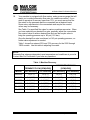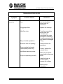
1
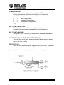
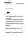
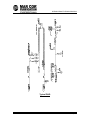
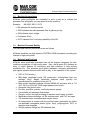
M4-SERIES
WATER PURIFICATION MACHINES
M4-2200 – M4-13200
Operation
and Maintenance Manual
1238160 Rev. D
23May11
This page intentionally left blank
1238160 Rev. D
23May11
OPERATION AND MAINTENANCE MANUAL
M4-SERIES WATER PURIFICATION MACHINES
M4-2200 – M4-13200
TABLE OF CONTENTS
Page
1-1
CHAPTER ONE:
GENERAL INFORMATION
Section
General Information and Principles of
Operation
Machine Nomenclature
Machine Permeate Quality
Materials and Features
Specifications for M4-Series Machines
1-7
1-7
1-7
1-8
CHAPTER TWO:
INSTALLATION
2-1
Section
Mounting
Plumbing
Electrical
2-3
2-3
2-4
CHAPTER THREE:
PREPARATION AND START-UP
3-1
Section
Pretreatment for Water Purification
Start-Up
3-3
3-4
CHAPTER FOUR:
OPERATION AND MAINTENANCE
4-1
Section
Daily Log Sheets
Prefilter
Flushing
Cleaning
Sepralator Replacement
4-3
4-3
4-4
4-4
4-7
1.1
1.2
1.3
1.4
1.5
1238160 Rev. D
2.1
2.2
2.3
3.1
3.2
4.1
4.2
4.3
4.4
4.5
A
1-3
23May11
CHAPTER FIVE:
OPTIONAL ACCESSORIES
5-1
Section
Level Controls
Conductivity Meter
Autoflush
Filters and Water Softeners
5-3
5-3
5-3
5-5
CHAPTER SIX:
TROUBLESHOOTING
6-1
APPENDIX A:
RETURN MATERIAL AUTHORIZATION (RMA)
PROCEDURE
1238160 Rev. D
5.1
5.2
5.3
5.4
B
23May11
M-Series Water Purification Machines
M-Series Water Purification Machines
M4-2200 – M4-13200
CHAPTER ONE:
DESCRIPTION
1238160 Rev. D
1-1
Description
M-Series Water Purification Machines
This page intentionally left blank.
1238160 Rev. D
1-2
Description
M-Series Water Purification Machines
1.1
General Information and Principles of Operation
These instructions give operating and maintenance details vital to the sustained
performance of the machine.
Reverse Osmosis (RO) is the removal of ionic, organic, and suspended
impurities from water by means of a membrane. Unlike a filter (“normal”
filtration), the feedwater or solution is separated into two streams by collecting
fluids from both sides of a pressurized membrane (“crossflow” filtration). A
semipermeable RO membrane, under sufficient pressure, allows passage of
purified water while rejecting and concentrating dissolved and suspended solids.
Mar Cor Purification manufactures a patented spiral-wound membrane package,
with a turbulent flow design. The membrane module (i.e. sepralator), also called
an element collects the purified water within a central tube (permeate tube), see
Figure 1.
Some operating definitions are provided to help you further understand your
machine:
PERMEATE RATE (PRODUCT WATER RATE) [QP]
This is the flow rate of purified water which has passed through the membrane
and out of the sepralator; expressed in gal/min (gpm) or gal/h (gph) [in metric,
liter/min (Lpm) or cubic meters/hour (m3/h). Specified permeate rates are
normally specified at 77°F (25°C).
1238160 Rev. D
1-3
Description
M-Series Water Purification Machines
CONCENTRATION
Concentration equals the Total Dissolved Solids (TDS) concentration of a
solution expressed as milligrams per liter (mg/L) or conductivity
(microSiemens/cm).
Cf
Cp
Cc
Cavg
=
=
=
=
Feed Concentration
Permeate Concentration
Concentrate Concentration
Average Concentration in machine
SALT (IONIC) REJECTION:
This equals the percent of dissolved salt rejected by the membrane,
calculated from an average concentration over the membrane.
SALT (IONIC) PASSAGE:
This equals (100% - rejection) or the percent of dissolved salts passed
through the membrane.
CONCENTRATION RATE (WASTE WATER RATE) [Qc]:
This is the flow rate of water stream containing rejected solids to drain in
gpm or gph (pm or m3/h).
FEED RATE [Qf]:
This is the flow of incoming water in gpm or gph (Lp or m3/h). Feedwater
rate equals permeate rate plus concentrate rate.
An example of how to calculate salt rejection and recovery is given below:
1238160 Rev. D
1-4
Description
M-Series Water Purification Machines
Given the system case in Figure 2:
Average Concentration (Cavg) = (Cf) 100 mg/L + (Cc) 146.9 mg/L
2
(Cavg) = 123.5 mg/L TDS
Rejection = (Cavg) 123.5 – (Cp) 6.2 x 100 = 95%
(Cavg) 123.5
Passage = (Cp) = 6.2 x 100% = 5.0%
(Cavg) 123.5
Recovery = (Qp) 2 gpm x 100 = 33%
(Qf) 6 gpm
FLOW DESCRIPTION:
The feedwater passes through a replaceable 5-micron cartridge filter,
which removes bulk suspended solids. Filtered water then flows to the inlet
control valve. This solenoid-controlled diaphragm valve is wired to the
on/off switch and opens when the machine is turned on allowing water to
flow to the pump inlet. When the machine is turned off, the valve closes,
preventing non-turbulent flow through the sepralators, that would lead to
shortened membrane life.
The pump feeds water to the sepralator housings arranged in parallel and
serial combinations. An arrow on each element housing indicates the
direction of water flow. The water is sepralated by the membrane within
the elements and leaves the housings in two streams as permeate and
concentrate.
Permeate from each sepralator housing is collected in a common manifold.
A pressure relief valve is installed to alleviate excessive backpressure
build-up. The permeate then flows through a flow meter and to the outlet
point of the machine.
The concentrate leaves the last sepralator housing and flows to the flow
control center. At this point, the recycle valve channels a predetermined
amount of concentrate into the pump inlet. This achieves more efficient
water recovery while maintaining adequate crossflow through the
sepralators. The other two ports of the flow control center lead to the
concentrate valve and final pressure gauge. The concentrate valve has
three functions: It controls the amount of concentrate flowing to the drain; it
controls the pressure within the machine, and it helps control the system
recovery. An optional autoflush solenoid is added to the flow control center
with an additional tee. The concentrate then flows through a flow meter
and to the outlet point of the machine.
1238160 Rev. D
1-5
Description
M-Series Water Purification Machines
Typical P&ID
1238160 Rev. D
1-6
Description
M-Series Water Purification Machines
1.2
Machine Nomenclature
M-Series water purification are numbered in such a way as to indicate the
permeate flow and quality you can expect from the machine.
Example:
M4-6600, 208, 6, 50-75
• M4 indicates the machine series
• 6600 indicates the rated permeate flow in gallons per day
• 208 indicates motor voltage
• 6 indicates 60 Hz
• 50-75 indicates the % recovery capability of the RO
1.3
Machine Permeate Quality
The permeate rejection performances are as follows:
M-Series machines use high rejection FASTEKu S4040 membrane, providing the
ultimate in high purity water.
1.4
Materials and Features
M-Series water purification machines have all the features necessary for safe,
continuous production of high purity water. Also, the M-series RO contains an
array of useful features for monitoring and data collection to help prolong
membrane life. This assumes good quality feedwater, adequate pretreatment
and regular operator attention, each shift or daily, to the operation of the system.
•
•
•
•
•
•
•
•
•
•
•
50% or 75% recovery
Multi-stage centrifugal pump, SB construction (nickel-plated cast iron
castings, Noryl* stages, remainder stainless steel) typically not
recommended for operation below pH 5.8
Base model electrical package includes NEMA-4X enclosure with a 115
VAC, 60 Hz or 230 VAC, 50Hz single-phase control circuit.
Automatic inlet shutoff valve
Pre-filter, post-filter, primary, and final pressure gauges
Concentrate and permeate flow meters
Gauges, valves, and rigid plumbing of stainless steel, brass, or plastic
Membrane element housings, all 304 stainless steel, with PVC end caps
316 stainless steel concentrate and recycle valves
All components in contact with the purified water (permeate) are either
non-leachable acceptable plastic (nylon, Noryl, polypropylene, PVC) or
stainless steel materials
All high pressure fittings are 304 stainless steel
1238160 Rev. D
1-7
Description
M-Series Water Purification Machines
•
Autoflush System – programmable, automated high velocity membrane
flushing for the longest membrane life; set at the factory and adjustable in
the field, includes a digital panel-mount timer, complete with push button
Manual Flush
•
An electrical package that includes alarm delay shutdown for low inlet
pressure condition to prevent pump damage should pressure fall below 15
psig (1 bar)
•
Conductivity monitor, panel-mounted, for permeate quality monitoring
•
NEMA-4X fiberglass electrical enclosure
1.5 Specifications for M-Series Machines
1.5.1 Feedwater
TEMPERATURE:
35-77° (22-25°C) [Not to exceed 85°F (29°C) unless specifically designed for
higher temperatures]
INLET PRESSURE:
Minimum: 30 psig (2.1 bar)
Maximum: 60psig (4.1bar)
CHLORINE (CONTINUOUS FEED):
For FASTEK TLC membranes 0 ppm
OPERATING pH:
Softwater [less than 1 grain per gallon 3.0-10.0 (gpg) or 17 mg/L hardness]
Unsoftened water (contact factory 5.5-6.0 with water analysis)
PRE-FILTER:
5-micron HYTREX cartridge (see machine label for part number)
INLET CONNECTIONS:
¾-inch FNPT (IPS)
1238160 Rev. D
1-8
Description
M-Series Water Purification Machines
1.5.2 Permeate (Product Water) Flow Rate
Stated on the RO test report form (assumes no permeate back pressure, 2000
mg/L TDS maximum feed concentration, and rated temperature).
To estimate permeate output with back pressure, use the formula below:
Permeate Flow on Label x Operating Pressure – (Permeate Back Pressure)
Operating Pressure
Permeate Back Pressure
Maximum:
60 psig (5.5 bar)
Permeate Outlet
3/4-inch FNPT
1.5.3 Concentrate Flow Rate
Stated on the RO test report form
Concentrate Outlet
3/4-inch FNPT
1.5.4 Typical Pure Water
Recovery
50-75%
1.5.5 Operating Final Pressure
Minimum
100 psig
Maximum
140 psig
1238160 Rev. D
1-9
Description
M-Series Water Purification Machines
1.5.6 Pump
Multi-stage centrifugal, approximately primary operating pressure of 100 psig
excluding line pressure.
1.5.7 RO Membrane Rejection
FASTEK TLC
Typical Ionic Rejection (TDS)
95-98%
Average Molecular Weigh Cutoff* 150 MW
*The molecular weight cutoff is based on the pore size of the membranes and the
nature (shape/size) of the organic molecule.
1238160 Rev. D
1 - 10
Description
M-Series Water Purification Machines
NOTES:
1238160 Rev. D
1 - 11
Description
M-Series Water Purification Machines
This page intentionally left blank.
1238160 Rev. D
1 - 12
Description
M-Series Water Purification Machines
M-Series Water Purification Machines
M4-2200 – M4-13200
CHAPTER TWO:
INSTALLATION
1238160 Rev. D
2-1
Installation Guidelines and Instructions
M-Series Water Purification Machines
This page intentionally left blank.
1238160 Rev. D
2-2
Installation Guidelines and Instructions
M-Series Water Purification Machines
2.1
Mounting
M-Series machines are equipped with a frame that supports the machine. Allow
at least 45 inches (114 cm) of space at the top of the sepralator housing(s) for
removal and loading of sepralators. If 45 inches (114 cm) are not available, the
entire membrane element housing may have to be removed for element
changes. At least 6 inches (15.2 cm) are required at the end of each sepralator
housing if the entire sepralator housing will be removed to replace sepralators.
2.2
Plumbing
2.2.1 Inlet Plumbing
The feedwater source is plumbed to the inlet using ¾-inch NPT fittings. A 1-inch
FNPT cleaning port is installed in the inlet plumbing. A pressure regulator is
installed between the permeate outlet and the membrane elements, so that if the
pressure exceeds 60 psig the regulator will allieviate the excess pressure.
2.2.2 Valves Required for (CIP) (Not Factory Installed)
A pipe tee is installed in the inlet line. Install a valve on the inlet and on the
cleaning port to facilitate cleaning the RO. Install a tee with 2 two-way valves or
a single three-way valve on the permeate and concentrate outlets to allow flow
back to the cleaning tank. Never operate the machine with the concentrate or
permeate lines blocked. Severe damage to the unit may result. (Refer to Figure
3 for representative system flow schmatic.)
2.2.3 Concentrate Outlet Connection
Install the CIP valve on the concentrate outlet and connect a ¾-inch hose or pipe
and run it to an open drain. The concentrate outlet plumbing should be placed at
a height at least equal to the height of the machine to avoid drainage from the
machine during non-operation. A siphon break may also be installed in the
concentrate line for added protection. The concentrate outlet hose can be any
length, and the diameter should match the outlet on the machine. [Maximum
back pressure is 60 psig (4.1bar).]
2.2.4 Permeate Outlet Connection
Install the CIP valve on the permeate outlet. The pure water (permeate) should
be transported to the point-of-use via non-corroding type tubing, pipe, or hose.
Examples are: food-grade flexible nylon tubing, stainless steel tubing, or PVC
hose. The permeate outlet is ¾-inch FNPT for all M-series RO’s.
1238160 Rev. D
2-3
Installation Guidelines and Instructions
M-Series Water Purification Machines
2.3
Electrical
M-Series models require two supply voltages, the control circuit voltage and a
separate motor voltage. All field wiring must comply with applicable local and
national electrical codes.
All M4 models are supplied with a single-phase, 115 VAC 60 Hz or 230 VAC 50
Hz control circuit with an 8-foot cord with plugs into a three-prong grounded
receptacle. A 20 amp dedicated service circuit is required for proper operation
(see wiring schematic).
The 2200 through 8800 models use a 1.5 Hp, 208-230/460 VAC, three-phase
motor. M-Series 11000 and 13200 models use a 2 Hp, 208-230/460 VAC, threephase motor. The motor is wired at the factory to an overload protection
magnetic motor starter. There is also a single-phase motor available on the 2200
and 4400 models only. These models use a 3Hp, 208-230VAC, 60 Hz, singlephase motor.
A 50Hz option for all M-series models is available. The 2200 through 8800 uses
a 3 Hp 190/380 VAC, three-phase motor. The 11000 and 13200 use a 5 Hp
190/380, three phase motor. A single-phase option is also available for 50Hz
models 2200 and 4400. These models use a 1-1/2 Hp, 220VAC, 50Hz, singlephase motor.
1.
Connect the control circuit power cord to 115 VAC, 60 Hz, or 230 VAC 50
Hz single-phase power.
2.
Connect the magnetic motor starter to 208-230/460 VAC or 190-220/380
VAC, three-phase or 115/230 VAC single-phase power to match the motor
voltage and phase. Check the tag (located on the motor starter) that
indicates the factory wiring. A separate, fused disconnect for the wiring with
proper protection for the Hp and the amp draw of the motor is
recommended.
WARNING:
Before obtaining access to terminals, all supply circuits must be
disconnected.
1238160 Rev. D
2-4
Installation Guidelines and Instructions
M-Series Water Purification Machines
1238160 Rev. D
2-5
Installation Guidelines and Instructions
M-Series Water Purification Machines
NOTES:
1238160 Rev. D
2-6
Installation Guidelines and Instructions
M-Series Water Purification Machines
M-Series Water Purification Machines
M4-2200 – M4-13200
CHAPTER THREE:
PREPARATION AND START-UP
1238160 Rev. D
3-1
Preparation and Start-Up
M-Series Water Purification Machines
This page intentionally left blank.
1238160 Rev. D
3-2
Preparation and Start-Up
M-Series Water Purification Machines
3.1
Pretreatment for Water Purification
All systems will operate most efficiently on filtered water with a pH of less than
6.5 and a Silt Density Index (SDI) of 5 or below. If the machine is operated on
higher pH water, other forms of pretreatment may be necessary. A water
analysis prior to start-up of the machine is required. To minimize the chances of
calcium carbonate, calcium sulfate, or other salt precipitation on the membrane,
Mar Cor Purification evaluates each application and water condition and makes
specific recommendations to assure continuity of the membrane sepralator
warranty. Data from the water analysis is processed with a computer program
analysis to determine if potential problems may exist. If the machine is to be run
at a different location than was originally intended, a new water analysis is
required for warranty consideration and should be sent to Mar Cor Purification for
review and recommendations for operation of the machine.
NOTE:
TLC membrane (only) must not contact the following chemicals or
permanent loss of rejection and/or permeate flow may result:
•
Free chlorine
•
Formalin (until after the RO unit has rinsed to drain for a minimum of
six (6) hours under normal pressures before first exposure to
formaldehyde).
•
Iodine compounds
•
Quaternary germicides
•
Cationic surfactants
•
Detergents containing non-ionic surfactants
•
Mar Cor Purification cleaners other than those approved for used
CAUTION:
A water softener should not regenerate while the machine is running unless
safeguards are used to be sure the machine is operated on softened water
during regeneration.
1238160 Rev. D
3-3
Preparation and Start-Up
M-Series Water Purification Machines
3.2
Start-Up
1.
Re-check the function and integrity of your pretreatment equipment.
Ensure that your water softener, activated carbon filters and iron filters
(where applicable) have been leak checked, backwashed, and thoroughly
rinsed for service, before starting up your RO unit.
2.
Attach the feedwater pipe work to the inlet of the machine.
3.
Check for leaks at all connection points.
4.
Turn on the feedwater gradually and check for leaks in the inlet plumbing.
No flow should go through the machine while the power is off and the inlet
solenoid is in the closed position.
5.
Attach tubing from permeate and concentrate outlet points, and run the
tubing to drain.
6.
Be sure the power to the motor starter is de-energized.
7.
Ensure that you made provisions for both voltages required to operate
your machine. The machine requires two power supplies, (1) the high
voltage for the motor operation, and (2) the control circuit power supply.
The factory provides the 115 VAC (or 220 VAC 50 Hz) power cord needed
for the control circuit. The motor electrical service must be field wired
directly into the motor starter on the machine. Bring your motor service to
terminals labeled “T” on the motor starter. Check the voltage label to
ensure that you have brought the correct voltage to the starter.
8.
With the machine ON/OFF switch in the OFF position, plug in the factory
supplied 115 VAC (or 220 VAC 50 Hz) power cord.
9.
Open your concentrate and recycle flow control valves two complete turns.
These valves are positioned on the flow control center of the machine.
This plumbing is located on the right rear section of the machine, near the
sepralator housings. The flow control center features a concentrate flow
control valve, a recycle flow control valve, and a pressure gauge sensor
point plumbed into the panel-mounted pressure gauge.
1238160 Rev. D
3-4
Preparation and Start-Up
M-Series Water Purification Machines
The proper adjustment of these valves is critical to the operation of the RO
machine. The concentrate valve determines the amount of rejected water
leaving the machine, and creates the operating pressure shown on the
pressure gauge. The recycle valve returns unused reject flow back into
the inlet stream to the RO pump.
It is important to balance the operating pressure and the respective flows
of these valves, to ensure that your machine is operating correctly. It is
important to understand the relationship of these two valves, the pressure
gauge, and your RO pump. The pump has a fixed amount of flow
produced, and the valves are control devices to distribute this fixed flow
amount. The pressure gauge is an indicator of applied membrane
pressure, at the flows set by the valves.
10.
Turn the ON/OFF switch to the ON position. Water will begin to flow
through the machine at this point but the pump will not start. Allow the
machine to operate in this manner for 10 minutes, to purge the air out of
the machine.
NOTE:
The high-pressure pump should not be operating at this time.
11.
As your machine is filling, check for leaks and repair, as needed.
12.
Turn the ON/OFF switch to the OFF position.
13.
Energize the power source to the motor starter. The pump should not
operate at this point.
14.
Check the rotation of the high-pressure pump by briefly turning the
ON/OFF switch to the ON position, as you look at the motor, or coupling
shaft. The motor should rotate clockwise if you are looking down on the
rotor motor end of the high-pressure pump. If the motor is not rotating
clockwise, change any two of the three leads (for 3-phase) into the motor
starter and recheck rotation. Always turn the power off to change any
wiring.
CAUTION:
Operation of the pump backwards for even a short time can cause damage to the
pump.
1238160 Rev. D
3-5
Preparation and Start-Up
M-Series Water Purification Machines
15.
Turn the ON/OFF switch to the ON position. The high-pressure pump will
operate and the machine will begin to build pressure. As you are
operating, make sure to watch the pressure gauge on the instrument
panel. The machine is designed to operate at 115 psi (15.2 bar).
NOTE:
Do not allow the pressure to exceed 140 psi. If the pressure exceeds 140 psi,
open the concentrate flow control valve until the pressure gauge shows 140 psi
or less.
As the machine purges the air and fills with water, the pressure will
gradually increase. You should see water flowing from the permeate and
concentrate flow meters. If you do not see flow from these points, turn the
machine off and return to Step 1.
CAUTION:
Never allow the machine to operate without adequate water pressure. This can
cause severely damage to the high-pressure pump.
16.
Gradually close the concentrate flow valve. As you close the valve, watch
the pressure gauge and your concentrate flow meter. Close the valve until
your concentrate flow meter displays your design flow, and you do not
exceed 140 psi. If you reach 140 psi before the valve is completely
closed, open the recycle flow control valve one full turn, then continue to
close the concentrate flow control valve. Continue to close the
concentrate flow control valve until it is completely closed and your
pressure is below 140 psi.
The concentrate flow control valve has a drilled orifice to ensure a predetermined amount of flow and pressure in the closed position. This
orifice is sized to operate the machine at 75% recovery.
17.
With the concentrate flow control valve fully closed and the pressure
below 140 psi, gradually close the recycle flow control valve until the
pressure reaches 140 psi.
Your machine is now operating at the design pressure and flow rates, in a
75% recovery configuration. Your specific needs or conditions may
dictate the need to operate the machine at a lower recovery. If you wish
to operate in a recovery configuration lower than 75%, Step 18 will explain
the necessary steps.
1238160 Rev. D
3-6
Preparation and Start-Up
M-Series Water Purification Machines
18.
Your machine is equipped with flow meters, and a pressure gauge that will
assist you in setting alternative flow rates for variable recoveries. If you
wish to operate at a recovery lower than 75%, you must ensure that the
flow rates for the permeate and the concentrate are at desired levels.
Some minor adjustments in the concentrate and recycle flow control
valves may be necessary.
See Table 1 for specified flow rates for various machine recoveries. When
you have selected your desired flow rate, gradually adjust the concentrate
flow control valve to achieve desired flow and use the recycle valve to
bring the operating pressure up to 140 psi (15.2 bar).
Once the desired flow rate is achieved, at 140 psi operating pressure, no
further valve adjustment is needed.
Table 1 shows flow rates at 50% and 75% recovery for the 2200 through
13200 models. Use this table in adjusting flow rates.
NOTE:
Permeate flow rates are dependent upon temperature and conditions at your site.
Contact Mar Cor Purification if you have any questions.
Table 1: Machine Recovery
PERMEATE FLOW [GPM(LPM)]
CONCENTRATE FLOW
[GPM(LPM)]
MODEL
50% Recovery
75% Recovery
50% Recovery
75% Recovery
M4-2200
1.5 (5.7)
1.5 (5.7)
1.5 (5.7)
0.5 (1.9)
M4-4400
3.1 (11.7)
3.1 (11.7)
3.1 (11.7)
1.0 (3.8)
M4-6600
4.6 (17.4)
4.6 (17.4)
4.6 (17.4)
1.5 (5.7)
M4-8800
6.1 (23.1)
6.1 (23.1)
6.1 (23.1)
2.0 (7.6)
M4-11000
7.6 (28.8)
7.6 (28.8)
7.6 (28.8)
2.5 (9.5)
M4-13200
9.2 (34.8)
9.2 (34.8)
9.2 (34.8)
3.1 (11.7)
1238160 Rev. D
3-7
Preparation and Start-Up
M-Series Water Purification Machines
19.
The system is now operational.
20.
Before putting the machine into final operation, continue to run the
permeate and concentrate streams to drain for at least 60 minutes. This is
done to ensure that all of the bactericide has been removed from the
sepralators.
21.
Connect the permeate line to the point-of-use of the permeate. Check for
leaks and ensure that you have no you have no kinks in hoses, or
blockage of any plumbing on the permeate and concentrate outlet lines.
22.
Make any final adjustments to flows and pressure according to Step 18, if
need be.
NOTE:
The element(s) in your machine are rated for certain flow rates at 77°F (25°C).
Maximum flow rates are achieved when the sepralators have been completely
rinsed and on-line for at least 24 hours.
23.
A daily log sheet that includes general operating conditions (pressures,
flows, concentrations, pH, and pretreatment conditions), and routine or
special maintenance (flushing or cleaning as needed) must be kept. Mar
Cor Purification will require this log sheet if a warranty question arises.
WARNING:
IF UNIT IS TO BE USED IN A DIALYSIS SETTING, THE RO SYSTEM MUST
BE DISINFECTED PRIOR TO PATIENT USE.
CAUTION:
New units with new or replacement sepralators must be rinsed to drain under
normal pressure for a minimum of six (6) hours before first exposure to
formaldehyde or irreversible damage may occur.
1238160 Rev. D
3-8
Preparation and Start-Up
M-Series Water Purification Machines
NOTES:
1238160 Rev. D
3-9
Preparation and Start-Up
M-Series Water Purification Machines
This page intentionally left blank.
1238160 Rev. D
3 - 10
Preparation and Start-Up
M-Series Water Purification Machines
M-Series Water Purification Machines
M4-2200 – M4-13200
CHAPTER FOUR:
OPERATION AND MAINTENANCE
1238160 Rev. D
4-1
Operation and Maintenance
M-Series Water Purification Machines
This page intentionally left blank.
1238160 Rev. D
4-2
Operation and Maintenance
M-Series Water Purification Machines
The operation and maintenance of your Mar Cor Purification M4 RO Machine is
relatively simple but requires regular data recording and routine preventative
maintenance. We cannot emphasize too strongly the importance of filling out the
daily log sheet during each operating shift. A data sheet was filled out upon
start-up containing pertinent facts on the operation of your machine. These two
records are invaluable in diagnosing the performance of the equipment and must
be kept for reference. If you have questions concerning the operation of your
machine or the method of data recording, contact the Mar Cor Purification
Technical Service Department.
The three preventative procedures, which must be done on a regular basis, are
as follows:
1.
Change the prefilter cartridge.
2.
Flush the machine daily.
3.
Clean the machine with approved Mar Cor Purification cleaners.
See the following sections for specific maintenance procedures.
4.1
Daily Log Sheets
A Daily Log sheet which includes general operating conditions (pressures, flows
and concentrations) and routine or special maintenance (prefilter changes,
flushing, cleaning, etc.), must be kept. Copies of the log can be made from the
template. Mar Cor Purification will require a copy of this log sheet if a
warranty question arises.
4.2
Prefilter
1.
A 5-micron prefilter is factory-installed to protect the elements and valves
from particles, which may be in the feedwater. The prefilter uses 2-3/4
inch (6.99 cm) diameter, 5-micron nominal rated cartridges. To order
replacements, see the standard parts list.
2.
The filter cartridges must be replaced, at a minimum, once per week or
after every 100 hours of operation, whichever comes first. A pressure
drop across the filter of 10 psig (0.6 bar) or more during operation
indicates the cartridge(s) need changing. Use only Mar Cor Purification
approved filters rated for 5-microns or less. Do not attempt to clean used
filters – install new replacements.
1238160 Rev. D
4-3
Operation and Maintenance
M-Series Water Purification Machines
NOTE:
Failure to change the filter according to these requirements will void the
warranty.
4.3
Flushing
The machine should be flushed at least once daily to remove sediment from
membrane surfaces. The autoflush should be utilized to accomplish system
flushing.
.
NOTE:
The Autoflush (AUF) system automatically flushes the machine and
eliminates the need for frequent manual flushing.
4.4
Cleaning
Cleaning the machine is vital because contaminants can build up on the
membrane surfaces, reducing the permeate flow rate and affecting the quality of
the permeate. A precipitated layer left on the membrane may cause permanent
chemical damage and reduce sepralator life. Observation of a decrease in either
permeate flow rate or rejection of salts, or an increased pressure drop across the
machine will indicate when cleaning is required. Cleaning may be required as
often as once every week or as infrequently as every two months, depending
upon the local water supply conditions. We suggest cleaning at least every
month to assure good membrane sepralator performance and long sepralator
life.
Mar Cor Purification offers a full line of chemical cleaners for specific cleaning
needs.
4.4.1 Cleaning Procedure
1.
With the RO machine running, open the CIP Permeate valve. After the
valve has been opened, close the permeate service valve and the CIP
tank drain valve. The CIP tank should begin to fill with RO permeate. If
any dirt or dust has collected in the tank while not in use, the drain valve
on the CIP tank should be opened to allow the particles to rinse to drain.
When the CIP tank is filled with RO permeate to the full line marked on the
CIP tank, place the ON/OFF switch on the RO machine in the OFF
position.
1238160 Rev. D
4-4
Operation and Maintenance
M-Series Water Purification Machines
2.
With the machine off, close the feedwater inlet valve and open the CIP
inlet valve. The permeate and concentrate streams must be diverted to
the cleaning container for recirculation. Ensure that the prefilter is clean.
A CIP pump is recommended to supply feed pressure in the machine.
3.
To circulate the cleaning solution through the machine with suction, the
low-pressure switch must be bypassed. Use a noncollapsible suction
hose or pipe to feed the machine.
NOTE:
Do not allow the machine pump to operate without concentrate flow. If
pump prime is lost when trying to clean on suction, positive inlet pressure is
required to reprime. No air should be sucked into the inlet during suction
cleaning.
4.
Turn on the machine (and CIP pump, if applicable) and recirculate the
cleaning solution at the same rate and pressure used for flushing. The
cleaning solution should be recycled for approximately 15 minutes or until
the solution temperature reaches 85°F (29°C). If heat rise occurs too
quickly, larger volumes of cleaning solution or the use of a heat exchanger
will slow the temperature rise. Turn the machine off and allow it to soak
for 10 minutes. Turn off the CIP pump control circuit if applicable.
NOTE:
It is possible to clean at temperatures of 100°F to 110°F (38°C to 43°C)
maximum, but lower temperatures (under 100ºF for normal cleaning) are
recommended. Use higher temps only sparingly for extreme fouling issues.
Do not allow the cleaning temperature to exceed 110°F (43°C) so as not to
cause damage to the membrane element. Allow the cleaning solution to
recirculate for 10 minutes. Turn the machine off and allow the sepralators
to soak in the solution for 20 minutes.
CAUTION:
Do not leave a cleaning strength solution in the machine for a period longer
than one hour. The cleaning solution may damage the sepralators and/or
the machine during an extended period of contact.
1238160 Rev. D
4-5
Operation and Maintenance
M-Series Water Purification Machines
5.
To flush the detergent from the machine, close the CIP inlet valve, open
the feedwater valve, and divert the permeate and concentrate to drain by
opening the CIP drain valve. Operate the machine as described in the
flushing section for at least 1 hour. The detergent is sufficiently flushed
when the permeate conductivity is restored to nearly its previous level.
6.
To return the RO to service, open the permeate, concentrate and feed
valves so that flow is routed as intended in the service mode. Close the
CIP permeate, CIP concentrate, and CIP feed valves. The RO is now
ready for operation.
1238160 Rev. D
4-6
Operation and Maintenance
M-Series Water Purification Machines
4.5
Sepralator Replacement
As time progresses, the efficiency of the sepralator will be reduced. In general,
the salt rejection does not change much until 2-3 years after installation, when
operated on properly pretreated feedwater. The permeate flow rate will begin to
decline slightly after one year of operation, but can be extended with diligent
flushing and cleaning of the machine. High pH feedwater and/or precipitation of
hardness can cause premature loss in rejection and even flow rate. The
following procedure is to be followed to replace existing sepralators in the
machine.
1.
Remove the end caps and clamps from all of the sepralator housings.
2.
Remove all of the sepralators from the sepralator housings in the direction
of flow (where possible). If necessary, a sepralator can be removed
against the direction of flow. A heavy-duty pliers or channel lock pliers
may be necessary to pull the old sepralator housing.
NOTE:
Do not run the machine in normal operation on water over 85°F (29°C).
CAUTION:
New units with new or replacement sepralators must be rinsed to drain under
normal pressure for a minimum of six (6) hours before first exposure to
formaldehyde or irreversible damage may occur.
1238160 Rev. D
4-7
Operation and Maintenance
M-Series Water Purification Machines
NOTES:
1238160 Rev. D
4-8
Operation and Maintenance
M-Series Water Purification Machines
M-Series Water Purification Machines
M4-2200 – M4-13200
CHAPTER FIVE:
ACCESSORIES
1238160 Rev. D
5-1
Accessories
M-Series Water Purification Machines
This page intentionally left blank.
1238160 Rev. D
5-2
Accessories
M-Series Water Purification Machines
5.1
Level Controls (Not Factory Installed)
Wire float switches, pressure switches or other level controls into the control
circuit line (prior to the switch as noted on the electrical schematic on the unit).
The following assures that the inlet valve, instruments, and pumps are not
powered when storage tanks are full: float switch assembly with cord, counterweight, and plastic float (used with an atmospheric storage tank).
5.2
Conductivity Meter
A factory-installed conductivity meter is mounted on the front panel of the
machine. The conductivity meter measures and displays the conductivity
resistivity of the water sample passing by unit’s sensor. The conductivity probe,
which is temperature compensated, is normally mounted in the permeate line,
but can also be mounted in the feed or concentrate line.
FEATURES:
• Single-meter readout – indicates conductivity
• Range –1 to 199.9 μS/cm
5.3
Autoflush
A factory-installed autoflush system is installed on 2,200- to 13,200-gpd models
and uses a standard 24-hour timer. It can increase the concentrate flow across
the sepralators at predetermined intervals. The timer controls a solenoid valve in
the concentrate line to increase flow.
5.3.1 To Set Time and Day of the Week
5.3.1.1 Set Day of Week
1.
Press the clock key and the day (1=Monday, 7=Sunday) key
simultaneously. The day of the week will change.
2.
Release both keys. The day of the week will be set
5.3.1.2 Set Hour
1.
Press the clock key and the hour (h+) key simultaneously. The hour will
change.
2.
Hold the clock key and the hour (h+) key simultaneously for more than
three seconds and the hour will shift faster.
3.
Release both keys. The hour will be set.
1238160 Rev. D
5-3
Accessories
M-Series Water Purification Machines
5.3.1.3 Set Minute
1.
Press the clock key and the minute (min+) key simultaneously. The
minutes will change.
Hold the clock key and the minute (min+) key more than three seconds
and the minutes will shift faster.
Release both keys. The minutes will be set.
2.
3.
5.3.2 To Set Programs
1.
2.
3.
•
•
•
•
•
•
•
•
•
•
4.
5.
6.
7.
8.
Press the timer key to enter the program mode.
Program 1’s turn-on time is ready to be set.
Press the day (1…7) key to select the day of the week. There are 10
settings for the day of the week to choose from:
Mo
Tu
We
Th
Fr
Sa
Su
Mo+Tu+We+Th+Fr
Sa+Su
Mo+Su
Press the hour (h+) key to set the hour).
Press the minute (min+) key to set the minute.
After setting Program 1’s turn-on time, press the timer key to set Program
1’s turn-off time.
Repeat steps 3-5 to set Program 1's turn-off time.
After setting Program 1’s turn-on/off times, repeat steps 1-7 set Programs
2-6
5.3.3 To Reset Timer
Press the reset key to reset the timer unit.
NOTE:
Once the reset key is pressed, the previous time and program will clear to
their initial states.
1238160 Rev. D
5-4
Accessories
M-Series Water Purification Machines
5.3.4 To Select ON/AUTO/OFF Mode
1.
2.
3.
Press the MANUAL key to select the appropriate mode
ON will turn on the timer.
AUTO will set the timer to the Program Time.
NOTE:
Moving from ON to AUTO will turn on the timer according to the next
Program’s turn-on time. Moving from OFF to AUTO will turn off the timer
according to the next program’s turn-off time. OFF will turn off the timer.
5.4
Filters and Water Softeners
Backwashable filters and softeners should be installed such that unfiltered or
unsoftened water will not be fed to the machine while the RO unit is operating.
Failure to do this may cause fouling or precipitation of calcium carbonate or other
materials onto the membranes.
1238160 Rev. D
5-5
Accessories
M-Series Water Purification Machines
NOTES:
1238160 Rev. D
5-6
Accessories
M-Series Water Purification Machines
M-Series Water Purification Machines
M4-2200 – M4-13200
CHAPTER SIX:
TROUBLESHOOTING GUIDE
1238160 Rev. D
6-1
Troubleshooting
M-Series Water Purification Machines
This page intentionally left blank.
1238160 Rev. D
6-2
Troubleshooting
M-Series Water Purification Machines
TROUBLESHOOTING GUIDE
Symptom
Low operating
pressure
Possible Causes
Remedies
Insufficient feedwater pressure or Open the feed pressure,
open the feedwater
flow
valve, check for
restrictions.
Clogged pre-filter
Replace the cartridge
High flow rates
Close the concentrate
valve, check the
permeate and
concentrate flow rates
and adjust if necessary.
Excessive permeate flow
may indicate a damaged
O-ring.
Dirty or fouled sepralators
Solenoid valve not opening
Pump rotating backwards
(three-phase power only)
Flush and clean the
sepralators.
Clean or replace the
solenoid valve
Insufficient electrical power
Pump not operating correctly
Switch any two threephase leads to the motor
starter.
Check the fuses or
circuit breakers,
measure the voltage.
See the pump
instructions
1238160 Rev. D
6-3
Troubleshooting
M-Series Water Purification Machines
TROUBLESHOOTING GUIDE
Symptom
Low permeate
flow rate
Possible Causes
Remedies
Low operating pressure
See the possible causes
for low pressure
Dirty or fouled sepralators
Flush and clean the
sepralators
Operating on cold water less
than 55°F (13°C)
Sepralators installed backwards
or damaged concentrate seal
Flow meter inaccurate
Install a hot/cold
feedwater tempering
valve if more permeate
flow is needed. Operate
with a feedwater
temperature of 72 to
77°F (22 to 25°C).
Install sepralators in the
direction of fluid flow.
Flush and clean the
machine immediately.
Sepralators with
damaged concentrate
seals should be cleaned
and may be returned for
repair.
Check the flow rate
manually with a
stopwatch and calibrated
container.
1238160 Rev. D
6-4
Troubleshooting
M-Series Water Purification Machines
TROUBLESHOOTING GUIDE
Symptom
Low
concentrate
flow rate,
normal or
higher than
normal
pressure
Possible Causes
Concentrate valve plugged
Concentrate outlet line
restricted
Remedies
Remove the concentrate
valve step and/or
disassemble the piping.
Clean the valve.
Examine the concentrate line
for obstructions or kinks;
repair or replace the tubing.
Flow meter inaccurate
Pressure does
not drop when
concentrate
valve is
opened
High operating
pressure
Dirty concentrate valve
Recycle or concentrate valve
plugged
Disassemble the piping to the
recycle valve and remove
foreign particles. Check the
concentrate valve stem.
Inaccurate pressure gauge
Replace or calibrate the
gauge as required
Restricted or reduced
permeate flow rate
1238160 Rev. D
Check the flow rate manually
with a stopwatch and
calibrated container.
Disassemble and clean the
piping to the valve
See the possible causes for
low permeate rate
6-5
Troubleshooting
M-Series Water Purification Machines
TROUBLESHOOTING GUIDE
Symptom
Possible Causes
Excessive
Restricted flow after pump
pressure drop outlet
[over 50 psig
(3.5 bar)] (high
primary
pressure – low
final pressure)
Telescoped sepralator covering
sepralator housing outlet port
Severely fouled or dirty
sepralators
Water flowing
when machine
is turned off
1238160 Rev. D
Inlet solenoid valve not
cleaning or sealing properly
6-6
Remedies
Check for blockage of the
concentrate flow at the inlets
and outlets of the sepralator
housings.
Ensure that the antitelescoping devise(ATD) is
located properly on the
sepralator.
Flush the machine, then clean
it with detergent.
Clean or replace the valve.
Clean the sepralators with
detergent immediately. Water
must not pass through the
inlet when the machine is off.
Troubleshooting
M-Series Water Purification Machines
TROUBLESHOOTING GUIDE
Symptom
Declining
rejection (high
permeate
conductivity)
Possible Causes
Remedies
Dirty or fouled sepralators
Flush and clean the sepralators.
O-ring seal broken or
damaged
Replace the O-ring, check the sealing
surfaces on the O-ring groove,
interconnectors and end caps. Replace
the damaged parts.
Change in incoming water
quality
Open the concentrate valve and flush.
Test the water for pH hardness, TDS and
iron content. A water analysis should be
sent to Mar Cor Purification for review.
Inaccurate conductivity
monitor fouled probe
Switch on,
unit not
operating
Pressurized storage switch
or float switch has cut power
machine
Calibrated the monitor with a standard
solution or check the range with another
conductivity meter. Replace or clean the
probe. Check the connections between
the probe and monitor.
Check the permeate back pressure or
position of float in the storage to tank.
Allow the machine to cool; check the
feedwater supply and/or amp draw of the
Fluid temperature higher
than 100°F (38°C) or thermal motor.
overload in motor
Electrical
machine
shutdown
No power to machine
Check the fuses or circuit breakers,
measure the voltage.
Motor and/or pump not
operating properly
See the pump instructions. Contact Mar
Cor Purification for possible repair or
replacement.
Restart the machine by pushing the alarm
by-pass. Check all possible alarm
conditions: inlet pressure, or motor starter
overload.
Alarm condition has turned
off machine
Motor starter overload,
heater tripped
Turn the switch off, rest the heater(s).
Check the motor amp draw and the line
voltage.
Timing relay
defective/burned out
Replace the relay.
1238160 Rev. D
6-7
Troubleshooting
M-Series Water Purification Machines
NOTES:
1238160 Rev. D
6-8
Troubleshooting
M-Series Water Purification Machines
M-Series Water Purification Machines
M4-2200 – M4-13200
APPENDIX A:
RETURNED MATERIAL AUTHORIZATION (RMA) PROCEDURE
1238160 Rev. D
A
RGA Procedure
M-Series Water Purification Machines
This page intentionally left blank.
1238160 Rev. D
A
RGA Procedure
M-Series Water Purification Machines
Returned Material Authorization Procedure
If you wish to return good for repair, warranty evaluation and/or credit, please
have your original sales order or invoice available when you call Mar Cor
Purification. Call (800) 633-3080 and speak with Technical Support. A Mar Cor
Purification Technical Support representative will provide instructions and a
return authorization number which needs to be clearly written on the outside
of the box used to ship your materials. All equipment must be shipped to Mar
Cor Purification with the freight prepaid by the customer. Call our Customer
Service Center with any questions or issues concerning freight claims and a
representative will discuss your situation.
All materials to be returned must be rendered in a non-hazardous condition prior
to shipping.
NOTE:
Machines must never be shipped with water in them; this will void the
warranty. Drain the machine completely before shipping and avoid freezing
before draining. The machine should be sanitized prior to draining.
1238160 Rev. D
A
RGA Procedure
M-Series Water Purification Machines
NOTES:
1238160 Rev. D
A
RGA Procedure
Call (800-633-3080) for additional information or visit www.mcpur.com.
14550 28th AVE N
Plymouth, MN
55447
USA
Ph: 800-633-3080
FAX: 952-988-6661