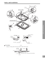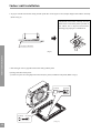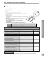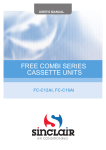
1
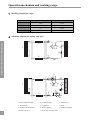
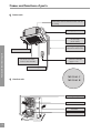
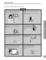
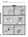
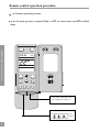
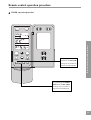
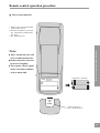
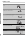
MUND CLIMA
®
SPLIT CASSETTE
COOL ONLY:
MUCS-24 C
MUCS-41 C
HEAT PUMP:
MUCS-24 H
MUCS-41 H
User's manual
installation
Operation mechanism and working range
1
Names and functions of parts
2
Safety cautions
4
Remote control operation procedure
6
Optimum operation
15
Trouble shooting
16
Installation notes
18
Care and maintenance
19
Technical specifications
23
Installation accessories and drawings
24
Indoor unit installation
26
Outdoor unit installation
34
Test and check items after installation
36
Thank you purchasing this MUNDOCLIMA air conditioner.Read this MANUAL carefully prior to use of
the air conditioner and then keep it properly for future reference.
Contents
Operation procedure
CONTENT
Operation mechanism and working range.
Working temperature range.
Indoor side DB/WB ()
Outdoor side DB/WB ()
maximum cooling
32/23
43/26
minimum cooling
21/15
21/15
maximum heating
27/-
24/18
minimum heating
20/-
-5/-6
Operation mechanism and working range
Schematic diagram for cooling only type.
2
3
4
1
5
6
7
6
7
8
2
3
11
2
3
4
1
5
8
9
2
3
10
1
1. Indoor heat-exchanger
2. Connecting pipe
3. Check valve
4. Accumulator
5. Compressor
6. Filter
7. Outdoor heat-exchanger
8. Master capillary
9. Auxiliary capillary
10. One-way valve
11. Four-way reversing valve
Names and functions of parts.
Indoor unit
Drainage device (built-in)
Drains water removed from the room unit during cooling
Drainage pipe
Air flow flap
(at air outlet)
Air outlet
The built-in air filter
removes dust and dirt
Remote controller
(page 6~14)
Air intake grille
Outdoor unit
MUCS-24 C
Names and functions of parts
Refrigerant piping
connection electric wire
MUCS-24 H
Refrigerant pipe
Air outlet
Air intake
2
Names and functions of parts.
Indoor unit
Drainage device (built-in)
Drains water removed from the indoor unit during cooling
Drainage pipe
Air flow flap
(at air outlet)
Refrigerant piping
connection electric wire
Names and functions of parts
Air outlet
The built-in air filter
removes dust and dirt
Remote controller
(page 6~14)
Air intake grille
MUCS-41 C
Outdoor unit
MUCS-41 H
Refrigerant pipe
Air outlet
Air intake
Air outlet
3
Safety cautions
Read the following carefully to assure safe use.
Warning
Check whether the installed stand is still firm
enough after the unit has operated for a long
time.
If a worn-out stand is left unfixed,the unit may
topple and do harm.
Do not remove protection grill nets from the
outdoor unit.
Do not reach hands or insert anything into the
unit air outlet.
Do not stand on the outdoor
unit or put anything on it, or
you may fall down or people
may get hurt by the falling
things.
If there is something abnormal (eg.burning
smell), cut off the power immeditely and contact service center.
Do not spray any paint or
pesticide on the unit, or it
may cause fire.
Safety cautions
Avoid direct air flow to your body and avoid
excessive heating or cooling,which may make
you feel uncomfortable and do harm to your
health.
Shut
off
power
If room air is stuffy, air the room by opening
door and window for a while, but please close
the curtains when operating the unit to prevent
conditioned air from leaking.
Never use wrong ampere rating fire.
Use of iron wire or copper wire may
cause the unit to break down or
cause fire.
iron wire
4
Safety cautions
Warning
Do not check or repair during the unit is
operating. It is very dangerous.
Do not use other
heating equipment near the air
conditioner.
It will affect the
cooling performance.
Safety cautions
Never place objects near the air intake and the air outlet of the unit.
It may affect performance or stop operation of the unit.
Do not splash water directly to indoor unit
It may cause trouble or electric shock.
5
Do not bang the remote controller.and do not
press the button of the remote controller with
pointed object, or the remote controller may
be damaged.
Remote control operation procedure
Name and Function-Remote control
Note:
Be sure that there are no obstructions.
The remote control signal can be received at a distance of up to about 10m.
Don’t drop or throw the remote control.
Don’t place the remote control in a location exposed to direct sunlight.
SWING button
FAN button
SWING
AUTO FAN
FAN
Presse this button to
change the fan speed of:
OPER
AUTO
AIR
TEMP.button
TEMP. increases 1=by pressing
button once,and decreases 1
by pressing button once.
At COOL mode operation, SET
TEMP. can be selected from 16 to
30.
At DRY mode operation, SET TEMP.
can be selected from 16 to 30.
At HEAT mode operation, SET
TEMP. can be selected from 16 to
30.
HR.
” COOL mode
” DRY mode
” FAN mode
” HEAT mode
1/0 button
Press this button to turn on
or turn off the unit.
MODE button
press this button to change the
operation mode in order of
AUTO
“
“
“
“
Remote control operation procedure
When it is pressed, the louvers
start to rotate automatically and
stop when repressed.
MODE
1/0
6
Remote control operation procedure
Name and Function-Remote control. (Remove the cover)
Note: This type of remote controller is a kind of new current controller.some buttons of
the controller which are not available to this Air conditioner will not be described
below.
Remote control operation procedure
Liquid crystal displayer It
shows all set contents.
SWING
FAN
AUTO FAN
OPER
AUTO
AIR
SWING HUMID LIGHT SAVE
TIMER
ON OFF
HR.
SLEEP
AIR
LIGHT
HUMID
TIMER ON TIMER OFF ANION
MODE
SLEEP button
Press this button to set
SLEEP operation.
TIMER OFF button
At operating, press TIMER
OFF button, set OFF TIME
in range of 0 to 24 hour to
stop the unit automatically.
SAVE
1/0
TIMER ON button
At stopping, press TIME ON
button, set ON TIME in
range of 0 to 24 hour to start
the unit automatically.
7
Remote control operation procedure
COOL mode operation procedure
According to difference between room temp. and set temp., microcomputer can control cooling
on or not.
If room temp. is higher than set temp., compressor runs at COOL mode.
If room temp. is lower than set temp., compressor stops and only indoor fan motor runs.
Set TEMP. should be in range of 16
to 30
K
=
4.Press FAN button, set
fan speed.
3.Press SWING button,
the louvers start to rotate automatically, and
stop when repress.
SWING
Remote control operation procedure
FAN
AUTO FAN
OPER
SWING
5.Press TEMP. button, set suitable
TEMP.
SLEEP
AIR
LIGHT
HUMID
TIMER ON TIMER OFF ANION
2.Press MODE button,
set
operation
mode.
MODE
SAVE
1/0
1.Plug in, press 1/0 button,then air
conditioner is turned on.
8
Remote control operation procedure
HEAT mode operation procedure
If room temp. is lower than set temp., compressor runs at HEAT mode;
If room temp. is higher than set temp., compressor and outdoor fan mortor stop, only indoor
fan mortor runs.
Set TEMP. should be in range of 16
to 30
K
=
The type of KF-xxx is not this function.
Remote control operation procedure
3.Press SWING button, the
louvers start to rotate
automatically, and stop
when repress it.
SWING
FAN
AUTO FAN
4.Press FAN button, set
fan speed.
OPER
AUTO
SWING
5.Press TEMP. button, set suitable
TEMP.
SLEEP
AIR
LIGHT
HUMID
1.Plug in, press 1/0 button,then air
conditioner is turned on.
TIMER ON TIMER OFF ANION
MODE
SAVE
1/0
2.Press MODE button,
set
operation
mode.
9
Remote control operation procedure
DRY mode operation procedure
If room temp. is lower than set temp., compressor ,outdoor and indoor fan mortor stop. If room
of set temp., Air conditioner is drying.If room temp. is higher than set
=2
temp. is between=
temp., it’s at COOL mode.
Set TEMP. should be in range of 16
to 30
K
=
3.Press SWING button,
the louvers start to rotate automatically, and
stop when repress it.
SWING
Remote control operation procedure
=
FAN
AUTO FAN
OPER
SWING
4.Press TEMP.button,set
suitable TEMP.
SLEEP
AIR
LIGHT
HUMID
TIMER ON TIMER OFF ANION
2.Press MODE button,set
operation mode.
MODE
SAVE
1/0
1.Plug in,press 1/0 button,then air
conditioner is turned on.
10
Remote control operation procedure
AUTO mode operation procedure
Remote control operation procedure
=
for HEAT
At AUTO mode operation, standard TEMP. is 25
for COOL mode and 20
mode.
SWING
FAN
AUTO FAN
OPER
AUTO
SWING
SLEEP
AIR
LIGHT
HUMID
TIMER ON TIMER OFF ANION
MODE
SAVE
1/0
1.Plug in,Press 1/0 button, then
air conditioner is turned on.
2.According to room temp.,microcomputer can automatically set
=====
operation
mode,so as for best effect.
11
Remote control operation procedure
TIMER operation procedure
SWING
FAN
AUTO FAN
TIMER
ON OFF
HR.
SLEEP
AIR
LIGHT
HUMID
TIMER ON TIMER OFF ANION
MODE
SAVE
At stopping,press TIME
ON button, set ON TIME
in range of 0 to 24 hour to
start the unit automatically.
1/0
Remote control operation procedure
SWING
At operating,press TIMER
OFF button.set OFF TIME
in range of 0 to 24 hour to
stop the unit automatically.
12
Remote control operation procedure
SLEEP mode operation procedure
in 1
When the unit is cooling or drying, if SLEEP operation is set, TEMP. would increase 1
in 2 hour. Indoor fan motor runs at low speed.
hour and 2
When the unit is heating , if SLEEP operation is set, TEMP. would decrease 1
in 1 hour and
2
in 2 hours. Indoor fan motor runs at low speed.
Remote control operation procedure
4.Press FAN button, set
fan speed.
3.Press SWING button,
the louvers start to rotate
automatically, and stop
when repress.
SWING
FAN
AUTO FAN
6.SLEEP button
Press it to set SLEEP
operation.
OPER
SWING
5.Press TEMP. button, set suitable
TEMP.
SLEEP
AIR
LIGHT
HUMID
TIMER ON TIMER OFF ANION
2.Press MODE button,
set
op or
eration mode.
MODE
SAVE
1/0
1.Plug in, press 1/0 button,then air
conditioner is turned on.
13
Remote control operation procedure
How to insert batteries
Note:
Don’t confuse the new and
worn or different batteries.
Remove batteries when not
in use for a longtime.
The remote control signal
can be received at a distance
of up to about 10m.
2 Insert the 7# batteries
ACL
Remote control operation procedure
1. Remove the cover from the back
of the remote control.
2. Insert the two batteries ( Two AAA
dry - cell batteries ) and press button “ACL”.
3. Re - attach the cover.
OPEN
1 Remove the cover
3 Re - attach the cover.
14
Optimum operation
Adjust the room temperature properly
Adjust the room temperature properly for a comfortable
environment.
Never place anything under the indoor unit that is to be kept dry.
Water may drop from the indoor unit when the humidity
is over 80% or when the drainage outlet is clogged.
Optimum operation
Turn off the main power supply swittch when it is not to be used for long periods of time
When the main power switch is truned on,some watts of
electricity is being used even if the system is not operating.
Turn off the main power supply switch to save energy.
Shut
off
power
OFF
Do not open the doors and windows for a long time when air conditioner is operating
Cooling and heating performance will be affected if the
doors and windows are open for a long time.
Place TV, radio, stereo, etc. at least 1m away from the indoor unit and the remote controller.
It may cause interference in the picture or sound.
Avoid direct air flow to pets and plants.
It may do harm to them.
15
Trouble shooting
Warning
* In case of something abnormal (such as bad smell), shut off the power switch immediately and contact service center.
* Do not repare the air conditioner by yourself because wrong repair may cause fire,please contact service center to do
it for you.
Check item shown below before contacting service center.
Cause
Corrective Measures
The system does not
Pause off or fuse broken
Change fause or replace fuse
operate at all
Power off
It will restart when power is on
Loose plug
Put the plug into place
Batteries of remote controller fall
Replace batteries
Out of the remote controlling range
Keep distance in 8m or less
The system stops right
Object at the air intake and
Romove them
after it is started
air outlet of the air conditioner
Cooling and heating is
Object at the air intake and
melfunctioning
air outlet of indoor and out door units
Trouble shooting
Symptom
Romove them
Wrong temperature setting
Refer to p6
Low fan speed
Refer to p6
Air direction is not correct
Refer to p6
Doors or windows are open
Close them
Direct sunshine
Close the curtain or blinber
Too many people in the room
Too many heating sources
Dirty air fliter
Clean it
Note:
If trouble still exists after checking the about items,please contact service center.
16
Trouble shooting
The following are not troubles
“ Trouble”
Cause
The unit does not
Restart right after stopping
Once the unit is stopped, it will not operate
operate when
Press SET TEMP.and then release immediately.
for about 3 minutes to protect it
Power is switched on
Wati for 1 minute
When cooling
Room air is chilled rapidly and becomes
Mist is emitted
foggy.
Outdoor unit is hot
after the unit is stopped
Compressor is emitting heat to get ready
for restarting.
Noise
Buzz is heard at starting
It’s the starting sound of thermostat and
Trouble shooting
will turn low after 1 minute.
Sound of running water can be heard
This is caused by the refrigerant flowing
during operation
inside the unit
A“ shuh” sound which is heard at the start
This is the noise of refrigerant caused by
or immediately after the stop of operation
flow stop and flow change.
or which is heard at the start or immediately The noise is heard when the drainage pump
after the stop of defrosting operation.
is in operation.
A continuous low“ shah” sound is heard
when the system is in cooling operation or
at a stop.
This is caused by the panel expanding or
Dust from the units
Cracking noise can be heard during or after
contracting due to the change in
operation.
temperature.
Starting operation after not using for a long
Dust absorbed by the unit blows out
time.
Wind from the outlet
smells
17
During operation
This is caused by the odors in the room
which have gotten onto the air conditioner
Installation notes
Location
=
=
The air conditioner must be firmly installed and 34
liability checks must be done every year.
Avoid place whthin easy reach of young children.
Avoid other heat sources or dircect sun light.
Install indoor unit away from TV set or radio.
Avoid where inflammable gas is likely to leak.
At salty coastal areas or special areas such as the vicinity
of a sulphurous hot spring,please contact dealer before
installation to make sure it is safe to use the unit.
Not to be installed in laundries.
=
=
==
=
=
=
=
=
=
Select a place with good ventilation or it may affect
performance or increase noise.
Install the air conditioner on a foundation that can
withstand its weight.insufficient strength may result in
the fall of equipment and cause injury.
Select a place so as not to annoy neighbor with the hot
air or noise.
Never place objects near the air outlet or the unit,it may
affect performance or increase noise.
If there is abnormal noise during the operating,contact
dealer immediately.
Installation and transportation
=
=
=
=
Installation and transportation of the unit must be done
by skilled personnel.
Be sure to use only the specified accessories and parts
for installation, failure to use may lead to electric shock,
leakage or fire.
Carry out installation with consideration of strong winds,
typhoons,or earthquakes.Improper installation work may
result in accidents due to fall of equipment.
If the unit is to be moved to other place, please consult
dealer first.
Earth
Wiring arrangement
=
=
=
Make sure wiring is carried out by qualified personnel
according to laws and regulations and this manual,using
a separate circuit and suitable fuse.
Be sure to install an earth leakage breaker.
Diameter of power supply cord must be big enough.
(Refer to P24 about the sizes of diameter)
Installation notes
=
Noise
Be sure to connect the earth wire to earth device of the building.Install an earth leakage breaker.
Be sure to install enough ampere rating air power switch. (specifications are illustrated in the following
table) Do not connect the earth wire to gas or water pipes,lightning condutor or telephone earth wire.
Model
Air power switch
MUCS-24 C/H
16A
MUCS-41 C/H
20A
Water pipe
Gas pipe
Some parts of the water pipe are made of plastic
materials and not suitable for earthing.
If there is electrical leakage accidently from air
conditioner, it is easy to cause fire or explosion.
18
Care and maintenance
Please pull out the power plug after you used the air conditioner.
Warning
Pull out the power plug before cleaning
Do not splash water directly to the unit
How to clean the air filter
Screws
Care and maintenance
1.Open the suction grille
Use screwdriver screws the two screws.
Slide both knobs simultaneously as shown and
then pull them downward slowly.
2.Remove the air filters.
Slide knobs on the back of the suction grille
outward and remove the air filter.
Then romove three air cleaners on it.
3.Clean the air filter
Use vacuum or wash the air filter with water when
the air filter is very dirty,use neutral detergent and
water.Let the filter dry naturally at shady place.
Note:
Do not clean with hot water
Do not dry over fire
Do not run the air conditioner without the air filter.
19
Care and maintenance
4.Fix the air filters
Fix three air cleaner on the air filter and then fix the
air filter to the suction grille by hanging it to the
projected portion above suction grille.
Set air filter by sliding the knob on the back of the
saction grille inward.
=
=
Shut the suction grille.
How to clean the suction grille
1.Open the suection grille.
See step 1 of “ How to clean the air filter”
2.Remove the air filters.
See step 2 of “ How to clean the air filter”
3.Remove the suction grille
Open the suction grille at 45and then lift.
Care and maintenance
Refer to step 1.
4.Wash with water.
When the suction grille is very dirty,use soft
brush and neutral detergent.Shake off water and
dry in a shady place.
Notes:Do not wash with hot water.
5.Fix the suction grille
Refer to step 3.
6.Fix the air filter.
See step 4 of “ How to clean the air filter”
7.Close the suction grille
Refer to step 1.
20
Care and maintenance
Changing air cleaner
See step 1 of “ How to clean the air filter”
1.Open the suction grille
2.Remove the air cleaner
Remove the air filter,and remove the air cleaner
affter unscrewing.
Care and maintenance
3.Take off packing bag and put in new static
electricity fiber filer,then fix them on the air filter.
4.Fix the air filter
See step 4 of “ How to clean the air filter”
Air cleaner functions and service cycle time
21
=
Absorbs bad smell in air such as corbon monoxide carbon dioxide,benzol, gasoline and so on.
=
Absorbs harmful objects bigger than 1.0 um in air such as dust,flower power, germ, virus and so on.
=
It can be used for about half a year to one year.
Care and maintenance
How to clean the air outlet and case.
Clean with soft cloth or use water and neutral detergent.
Do not use gasoline,benzene,thiner,polishing powder,liquid insecticide,which may cause discoloring
or warping.If the air flow flap is very dirty,you may remove it to clean as shown below.
=
=
Detach and fix the flap
2.Fix the flap
Set the ribs on the sides of the air outlet to the slit
of the flap and then screw together to fix the flap.
Before starting the air conditioner for the first time in the season
Care and maintenance
1.Detach the flap
Loosen the screws on the sides of the flap.
clean with soft cloth.
1.Check to make sure no objects obstructing the intake
and outlets parts on both the indoor and outdoor units.
2.Check to make sure ground wire is connected and
that it is not damaged.
3.Check to make sure air filter has been cleaned.
4.Turn on the power 6 hours before starting the air
conditioner.
End of seaseon cleaning
1.Clean the filter and the body of the unit.
2.Turn off power.
3.Clear outdoor unit of dust.
4.If there is any rust in the outdoor unit, this should be
painted over to prevent the rust from spreading.
22
23
3800
7000
24000
6000
30/75
5/8"
3/8"
840
3.9
1180
230-50-1
47
59
* Datas listed above may be changed without informing the consumers;
* Please see the nameplate for actual datas.
Cooling rated power
Heating rated power
Drying capacity
Recycling air volume
Volt-Fhase-Frecuence
Noise level indoor unit
Noise level outdoor unit
Width indoor unit
Height indoor unit
Depth indoor unit
Width outdoor unit
Height outdoor unit
Depth indoor unit
Weight indoor/outdoor units
Gas pipe diameter
Liquid pipe diameter
Cooling line max. length
Unevenness max.
Heating capacity
Cooling capacity
W
BTU/h
Kcal/h
W
BTU/h
Kcal/h
W
W
L/h
m3/h
V-Hz-Ph
dB(A)
dB(A)
mm
mm
mm
mm
mm
mm
Kg
inch
inch
m
m
MUCS-24 C
-
-
MUCS- 24 H
R407C
12000
7000
41000
24000
10350
6000
7000
24000
6000
4900
3800
4100
6.8
3.9
1860
1180
400-50-3
230-50-1
54
47
62
59
950
950
240
950
1250
840
412
38/112
30/75
3/4"
5/8"
1/2"
3/8"
20
15
MUCS-41 C
Technical specifications
Technical specifications
38/112
3/4"
1/2"
1250
12000
41000
10350
12000
41000
10350
4900
4800
6.8
1860
400-50-3
54
62
MUCS-41 H
Technical specifications
Installation accessories and drawings
Accessories
Shape
Notes
Quantity
1
Drainage hose
1
2
Clamp
1
3
Washer
10
10
4
Clamp
4
L=200
5
Paper pad for installaition
1
6
Screws
4
7
Washer fixing plate
4
8
Insulation for gas pipe
1
9
Insulation for liquid pipe
1
10
Big sealing pad
1
5 160 300
11
Sealing pad
1
5 45 300
12
Small sealing pad
2
3 30 150
13
outdoor unit drainage head
1
14
Sealing bar
1
120 65 25
15
PVC tape
2
30 10
16
Remote controller
1
17
Battery
18
Plastic sleeve
2
1
19
20
21
Signal control wire
Signal control wire
Power supply wire
ST4.8 13-F
7 1.5V
H07RN-F 5 1
MUCS-24 H
MUCS-41 C
H07RN-F 4 1
MUCS-24 C
MUCS-41 C
MUCS-41 H
H07RN-F 4 1
MUCS-41 H
H05RN-F 3 0.75
MUCS-24 C
MUCS-24 H
MUCS-41 H
H05RN-F 2 0.75
MUCS-24 C
H07RN-F 5 G 1.5
MUCS-41 H
MUCS-41 C
1
1
1
H05VV-F 3 G 1.0
H07RN-F 3 G 2.5
22
Power connecting wire
1
23
Corrugated pipe
4
24
Air cleaner hold
3
25
Air cleaner
3
26
Screws
8
27
Stem
2
H05RN-F 3 G 0.75
ST4.2 9.5PA
Installation accessories and drawings
Name
MUCS-41 H
MUCS-24 H
MUCS-24 C
MUCS-24 C
MUCS-24 H
MUCS-41 H
24
Installation accessories and drawings
Installation drawings
Indoor unit
1500mm
or more
2300mm or more
Installation accessories and drawings
H
20mm or more
Air intake
1500mm
or more
unit: mm
Model
H
MUCS-24C/MUCS-24H
260
MUCS-41C/MUCS-41H
340
Ground
(Fig.1)
Outdoor unit
500mm
or more
500mm
or more
1000mm
or more
300mm or more
Air outlet
2000mm
or more
Ground
Note:
Air conditioner must be installed by skilled personnel according to this manual.
25
2000mm
or more
(Fig.2)
1000mm
or more
Indoor unit installation
Location
1.Do not place object near the air oulet so that conditioned air can reach the whole room.
2.Be sure to install the indoor unit firmly and horizontly.
3.Select the place that can support 4 times of the indoor unit’s weight and will not increase noise and vibration.
4.Select a place easy to drain water and connect with the outdoor unit.
5.Make sure there is enough space for maintenance and make sure the distance between the unit and ground is 2.3m or
more.
6.Make sure the suspension bolt pitch can hold 4 times of the indoor units’s weight,otherwise,you should strengthen
the suspension bolt pitch.
Air conditioner
1.Keep enough distance from the kitchen.
2.The appliance shall not installed in the lundary
4m or more
Exhauster with big
enough capacity
Heating
Indoor unit installation
Note:
950 Decoration panel
890 ceiling opening
840 Indoor unit
780 Suspension bolt pitch
Ceiling opening and suspension bolt (M10) pitch demension.
Refrigrant piping
* Drilling of ceiling
must be done by
qualified personnel.
780 Suspension bolt pitch
840 Indoor unit
890 ceiling opening
950 panel
A
(160)
Hanger bracket
Ceiling
View as seen from A
20 or more
Note
Installation is possible with a ceiling dimension of 890 (marked with * can be 910), but the ceiling-panel overlapping
dimension must be 20mm or more.
26
Indoor unit installation
Indoor unit installation
1.Install the indoor unit temporarily.
Attach the hanger bracket to the suspension bolt.Be sure to fix it securely by using a nut and washer from the upper
and lower sides of the hanger bracket.the washer fixing plate =will prevent the washer from falling.
Refer to the paper pad for installation =for ceiling opening demension.
The center of the ceiling is indicated on the paper pad for installation,the center of the unit is indicated on the label
attached to the unit and on the paper pad for installation.
Fix the paper pad to the unit with screws =( 3)
3.Refer to diagram 3, adjust the unit.to the right position for installation.
4.Check if the unit is horizontally level.
The indoor unit is equipped with a built-in drainage pump and float switch.at each of the unit’s 4 corners,verify that
it is level by using a water level or a water filled vinyl tube.(If the unit is tilted against condensate flow,the float
switch my malfunction and cause water to drip.)
5.Remove the washer fixing plate= used for preventing the washer from falling and tighten the upper nut.
6.Remove the paper pad for installation=.
Indoor unit installation
Field procurement(M10)
Washer
(attached)
Inset
Washer fixing plate
(attached)
Tighten(double nut)
(Securing the hanger bracket)
(Securing the hanger bracket)
Fix screw of end of piping at the corner of
drainage trough
Center of ceiling opening
Pager pad for
installation
Screw
Water level
Vinyl tube
Warning
27
Fix paper pad for installation
Tighten the nut to prevent the unit from falling.
(attached)
Indoor unit installation
Connection of refrigerant pipe
Besure to use both a spanner and torque wrench together as shown in the drawing,connecting or disconnecting pipes
to/from the unit.
Refer to table 1 to determine the proper tightening torque (over tightening may damage the flare and cause leaks.)
When conecting the flare nut,coat the flare both inside and outside with refrigerating machine oil and initially
tighten by hand 3 or 4 turns.
Check the pipe connector for gas leaks,then insulate it as shown in the drawing below.
Use sealing pad (11) to wrap joint between gas pipe and the insulation(8).
Coat here with refrigerating machine oil
Torque wrench
Piping joint
Gas piping
Liquid piping
Insulation for fitting
(atteched )
(for liquid pipe)
Insulation for fitting
(atteched )
(for gas pipe)
Piping joint
Indoor unit installation
Sealing pad
(wrap the joint with the sealing pad)
Flare nut
Table 1
Pipe gauge
Tightening torque
3/8”
30 to 40 N.m
1/2”
45 to 50 N.m
5/8”
60 to 65 N.m
3/4”
70 to 75 N.m
The maximun leagth for refrigerant piping is 25 meters (but KF(R)-50TW/E1N is 15 meters),when the length exceeds 10
meters,you should charge additional(refrigerant as shown in following for per-meter added).
28
Indoor unit installation
Drainage pipe
1.Installation of drainage pipe.
The diameter of the drainage pipe should be greater than of equal to the diameter of the connecting pipe[vinyl tube,
pipe size:25mm(outer dimension)]
Keep the drainage pipe short and sloping downwards at a gradient of at least 1/100 to prevent air pockets from
forming.
If the drainage hose cannot be sufficiently set on a slope,add a drainage raising pipe.
To keep the drainage hose from sagging,keep space between hanging hooks at 11.5m.
1-1.5mm
Wrong
Right
Use the attached drainage hose and clamp .Insert the drainage hose into the drainage socket up to the grey tape.
Tighten the clamp until the screw head is less than 4 mm from the hose.
Wrap the big sealing pad around clamp of the drainage hose to insulate.
Insulate the drainage hose inside the room.
Big sealing pad
Clamp
Clamp
Tape(grey)
Drainage hose
4mm Or less
Precoutions for drainage raising pipe
Install the drainage raising pipe at a height of less than 280 mm.
Install the drainage raising pipe at a right angle to the indoor unit and no more than 300 mm from the unit.
300mm or less
Drainage raising
(attachect)
Ceiling
1-1.5mm
280mm or less
Drainage raising pipe
220mm
Note
Hanger bracket
The incline of attached drain hose should be 75mm or
les, so that the drainage socket does not have to stand
additional force.
If converging multiple drainage pipes,install according
to the procedure shown below.
500mm or less
75mm or less
500mm or less
Indoor unit installation
1/100 Gradient or more
T-joint converging drainage pipes
100mm or more
29
Select converging drainage pipes whose gauge is suitable for the operating capacity of the unit.
Indoor unit installation
2.After finishing installation,check if drainage water flows smoothly.
Add approximately 600 cc of water to the drainage trough through air outlet or inspection hole slowly and check
drainage flow.
When electric wiring is finished,check drainage flow during cooling operation.
Method of adding water.
Drainage pipe
100mm or
Service cover
Inspection hole
Adding water through inspection hole
Warning:Befone obtaining access to terminals, all supply circuits must be disconnected.
Electric wiring
All field supplied parts and meterials must conform to local laws and regulations.
For electric wiring,refer to “ WIRING DIAGRAM ”attached to the unit body.
All wiring must be performed by a skilled technician.
A circuit breaker capable of shutting down power supply to the entire system and which have at least 3 mm contact
seperation in each jole must be install in the fixed wiring.
Earth properly.
Wiring must conform to national laws and regulations.
The fixed wiring must be installed with a protector with not more that 30 mA leakage current.
If the supply cord is damaged, it must be replaced by the manufactory or its service agents or a similarty qualified
person in order to avoid a hazard.
Indoor unit installation
Service draginage outlet
(with rubber stopper)
(use this outlet to drain
water from the drainge
trough)
Wiring of unit and the controller
Wiring of the indoor unit.
Remove the control box lid(1),pull the wires inside through rubber bushand wiring according to the “ WIRING
DIAGRAM ”,then tighten it with clamp.
Wiring of the controller
Remove the control box lid(2),pull wires inside through rubber bush and connect to the contrroller.
Wrap the wire with sealing pad(12).
After wiring,tighten it with clamp and fix the control box lid(1),(2).
Heating and cooling:connect the rubber wire (5-cords) to the power supply terminal board in properly.
Cooling:connect the rubber wire (3-cords) to the power supply termiral board properly.
30
Indoor unit installation
L1 L2 L3 N
N L
three phase
one phase
L
N
Power supply terminal board
(3 for cool/heat
5 for cool only)
Come from
outside unit
Clamp
Indoor unit installation
Clamp
Rubber bush
Control box lid (2)
Seal here to avoid leakage
Rubber bush
Control box lid (1)
Precautions:Be sure to connect the indoor unit and outdoor unit at right poles.
Installation of panel
1.Set the panel to the indoor unit body by matching the position of the swing flap motor of the decoration panel to the
piping position of the panel to the piping position of the indoor unit as shown in fig.4.
2.Install the decoration panel
(1) Hang the latch,which is located on the opposite side of the swing flap motor on the panel,temporarily to the book
of the indoor unit. (2 Positions)
(2) Temporarily hang the remaining 2 latches to the hooks on the sides of the indoor unit.(be careful not to let the swing
motor lead wire get caught in the sealing material.)
(3) Screw all 4 hexagon head screws located right beneath the latches in approximately 15mm.(panel will rise)
(4) Adjust the panel by turning it to the arrowed direction in Fig.4 so that the ceiling opening is completely covered.
(5) Tighten the screws until the thickness of the sealing material between the panel and the indoor unit body is reduced
to 58 mm.
31
Indoor unit installation
Hook
Latch
Piping position
Indoor unit installation
Swing flap motor
Sealing material
Indoor unit
Ceiling
5
Air outlet
8mm
Panel
(Fig.4)
Precautions
1.Improper screwing of the screws may cause the troubles shown in Fig.5
Air leak
Air leak from ceiling
Contamination dew condensation,dew dripping
(Fig.5)
32
Indoor unit installation
2. If gap is still left between the celling and the panel after screwing the screws,readjust height of the indoor unit body
(Refer to Fig.6)
Adjustment of the indoor unit body from the
holes in the corner of the panel is possible if
the indoor unit is kept leveled and the
drainage pipe piping etc is unaffectecd.
No gap is allowed
Indoor unit installation
(Fig.6)
* After fixing,be sure no gap left between the ceiling and the panel
3.Wiring of the decoration panel.
Connect te joints for swing flap motor lead wire(at 2 places) installed on the panel (Refer to Fig.7)
At body
At body At panel
( Fig.7 )
33
At panel
Outdoor unit installation
Selecting installation site
Select an installation site where the folliwing conditions are satisfied and that meets with your customer’s approval.
Places which are well-ventilated.
Safe places which can withstand the unit’s weight and vibration and where the unit can be installed level.
Places where the unit does not bother next-door neighbors.
Places where there is no possibility of flammable gas leak.
Places where things distressed in water do not exist because water drains off the outdoor unit.
Places where servicing space can be well ensured.
Places where strong wind can not blow directly to outdoor unit.
572mm
(Fig.8)
Gas pipe
Single valves
Liquid
pipe
Indoor unit installation
1.Install the unit firmly with combination of
M10 or more bolts and nuts on the
foundation that can fully support the weight
of the unit.and make sure the unit stand
vertically.
2.Do not installing the unit on the top of
building.
3.If there is noise caused by vibration add
rubber between the unit and the foundation,
Please.
4.When the air conditioner is heating or
defrosting,drain water of the outdoor unit
to an appropriate place with the drain hose.
5.Fixing mothod:Fix the outdoor drainage
hose head in the hole of the chassis,then
connect the drainage hose with the mouth
of drainage pipe.
378mm
Outdoor unit installation
Gas valves
Liquid valves
Connecting the pipe.
1. Remove the flare nuts of the valves.
2. Match the piping center,tighten the flare
nuts with hand.
3. Tightening the flare nuts with a driver.
4. Romove the nuts of one-way valve.
5. Evacuate from the one-way valve with a
vaccum pump until the vacuum meter is 5
Torr,and keep up evacuating 1 hour or more.
6. Turn off the valve and fighten the nuts.
7. Fully open valves.(Fig.9)
8. Tighten the nuts,then check whether there
is gas leaking out.
* Moisture inside pipeline must be less 200
PPm.
(Fig.9)
Lo
Hi
Vacuum meter
Nuts
(Fig.10)
Liquid pipe Gas pipe Vacuum pump
34
Outdoor unit installation
Electric wiring
(1) Read the name plate carefully,then arrange wiring according to the “ WIRING DIAGRAM ”.
(2) A circuit breaker capable of shutting down power supply to the entire system must be installed.
(3) Earth properly.
(4) All wiring must be perfomed by a skilled electrican according to the “ WIRING DIAGRAM ”.Wrong wiring may
cause fire of electric shock.
Connect the power connecting wires
(1) Remove the front side plate (Fig.11)
(2) Break through the hole for wires and put on rubber bush.
(3) Pull all wires through the rubber bush.
(4) Connect the outdoor unit according to the “WIRING
DIAGAM” of outdoor unit.Make sure to wire firmly.
(5) Tighten the wires with clamp and clasp.
one phase
L
N
L1 N1
Indoor unit installation
Note
(1) Earth the units firmly.
Rubbe wire
Rubbe wire
(3-cord)
(3-cord)
(2) Wire the units firmly.
to power
to indoor unit
(3) Don’t pull the connector too forcefully.
(4) For cooling only type:
Connect the rubber wire (3-cords) to L.N1
of the power supply terminal board (8p) and the rubber wire (5cords) to L1,L2,L3,N
, of the power supply terminal board (8p) accordingly.
For cooling/heating type:
Connect the rubber wire (5cords )to the power supply
terminal coard (5p) properly.
three phase
L1 L2 L3 N
Rubbe wire
(5-cord)
to power
L N1
L1 L2 L3 N
Rubbe wire
(3-cord)
to indoor unit
(5) Connect the other wires porperly.
Do not pull the wire when fixing it with
wire clamp and clasp.
Do not let the wire too loose in the outdoor
unit compressor compartment.
Rubbe wire
(5-cord)
to power
Power supply terminal board
Rear side plate
Clamp
Clasp
Front side plate
Hole of wires and rubber bash
Cords
35
( Fig .11)
Test and check item after installation
1. Prepare for test
(1) Do not turn on the power switch before all installation is finsihed.
(2) Connect wires corectly and firmly.
(3) Open the check valve.
(4) Remove all dust.
2. Testing
(1) Turn on the power switch and press “1/0” button.
(2) Press “MODE”button select COOL,HEAT,FAN,etc to test whether it
operates mormally.
3.Emergency operation.
When the batteries fail or when the remote controller is missing,operate as
shown below.
* On stopping you can press the “AUTO”button on cover NO. ==unitl it is in “AUTO” mode.
The air conditioner select from COOL,HEAT,DRY,FAN
modes automatically.
On
operating,press the “AUTO”button,the air conditioner will stop.
*
Note
The“TEST”button on the cover No. is specially for testing the air conditioner.
When pressing it,the air conditioner will be forced to operate or stop.Do not press
it when air conditioner is in normal operation.
For the following items,take special care during construction and check after installation is finished.
Items to check
If not properly done,what is likely to happen
Is the indoor unit fixed firmly?
The unit may drop,vibrate or make noise.
Is the gas leak test finished?
It may result in insufficient cooling.
Is the unit fully insulated?
Condensate water may drip.
Does drainage flow smoothly?
Condensate water may drip.
Does the power supply voltage correspond to
The unit may malfunction or the components burn
that shown on the nameplate
out.
Check
Test and check item after installation
Test operation
The unit may malfunction or the components burn
Are wiring and piping correct?
Is the unit safely grounded?
out.
Risk of electric leakage.
The unit may malfunction or the components burn
Is wiring size according to specifications?
out.
Is something blocking the air outlet or intake
of either the indoor or outdoor units?
It may result insufficient cooling.
Have records of refrigerant piping length and
Volume of refrigerant charge in the system is not
additional refrigerant charge been made?
clear.
Note to the installer
Be sure to instruct the customer how to operate the system and show him/her the attached operation manual.
36