1
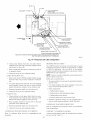
To Begin Component Self-Test:
¥.t_ _I_
Blower
access
panel
control.
No component
door
switch
operation
taken when manually
Failure
_
closing
iniury,
i. Remove
access
4. For approximately
Caution
to
must be
in electrical
R lead from furnace
door
enclosure.
nal on control
until
shock,
control.
(iumper)
If TEST/TWIN
longer
than 2 sec, LED
will
quick-connect
goes of£ Remover
ONLY
are jumpered
a. LED will
and ignore
component
b. Inducer
motor
component
c. After
is as follows:
display
combustion-air
furnace,
previous
starts
and reset
switch.
press
Condensate
button
to gas
occurs in buruer
supply
or im-
DO NOT jumper
check flame roll-out
manual
to reset
Trap With
trap must be PRIMED
be primed
of condensate
i.
test sequence
inadequate
condition
If necessary,
Condensate
from
test request.
Component
(flame rollout)
reset switch
switch.
Water
termi-
jumper
COM-24V terminals
flash rapidly
reset limit switch
condition
occur. The condensate
and
with a manual
will open and shut offpower
the COM-24V terminal
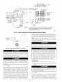
(See Fig. 31.)
NOTE:
operating
for continuity.
Step 2--Prime
3/16-inch
the LED
Correct
proper venting
this switch.
switch.
2 sec, short
are equipped
valve if an overheat
Before
to the TEST/TWIN
terminals.
power
door.
close blower
on control
can occnr.
could result
the thermostat
3. Manually
115-v
or death.
blower
2. Disconnect
opens
furnaces
in burner box. This switch
this switch for smwice purposes.
to follow this warning
personal
These
Remove
or proper
trap has 2 intemal
by pouring
draining
chambers
water into the inducer
may not
which can
drain side
trap.
upper
inducer
housing
drain
connection
cap.
(See
Fig. 55.)
stares
code 4 times.
and continues
to run until
Step g of
test sequence.
7 seconds
the hot suri_ace igniter
is energized
for 15
sec., then of£
d. Blower
motor
operates
on Continuous-FAN
speed
for I0
sec.
e. Blower
motor
operates
on HEAT
speed
for 10 sec.
f. Blower
motor
operates
on COOL
speed
for I0 sec.
g. Inducer
5. Reconnect
motor
door switch,
6. Operate
7. Verify
furuace
room
8. Verify
roolI1
and re-install
furuace
below
stops.
R lead to furuace
per instruction
shut
down
remove
tape l'rom blower
door.
on outer door.
by
lowering
thermostat
setting
temperature.
that furuace
restarts by raising thermostat
setting
above
temperature.
START-UP
Step
control,
blower
PROCEDURES
\
1--General
i. Furnace
must have a 115-v power
supply
properly
connected
and grounded.
NOTE:
polarity
Proper
polarity
is incorrect,
and furnace
must be maintained
control
for 115-v wiring.
LED status indicator
If
A99118
will flash rapidly
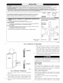
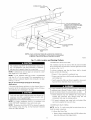
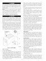
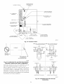
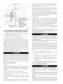
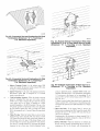
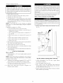
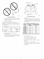
Fig. 55--Inducer
will not operate.
2. Thermostat
wire connections
at terminals R, W, G, and Y/Y2
nmst be made at 24-v terminal block on furnace control.
3. Natural
gas selwice
pressure
must not exceed
wc), and be no less than 0.16 psig (4.5-in.
4. Blower
access panel must
electrical circuit to furuace.
be
in place
2. Connect field-supplied ii2-in.
housing drain connection.
0.5 psig (14-in.
3. Insert field-supplied
wc).
to complete
Housing Drain Tube Cap
ID robe to upper
inducer
funnel into robe.
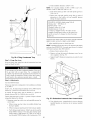
4. Pour 1 quart of water into l'unnelimbe. Water should run
through inducer housing, overfill condensate trap, and flow
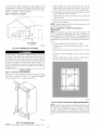
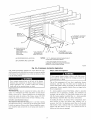
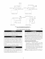
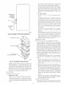
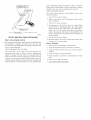
into open field drain. (See Fig. 56.)
l15-v
5. Remove funnel and robe from inducer housing and replace
drain connection cap and clamp.
39