1
Operating Instructions and Parts Manual
General Safety
Information (Cont’d)
15.Make sure the line voltage and frequency of electrical current supply
agrees with the motor wiring.
16. Do not attempt repairs to the electric motor. All repairs to the motor
must be completed at a licensed or
certified electrical motor repair
shop.
Do not touch an
operating motor.
Modern motors are designed to operate at
high temperatures.
! WARNING
17. Avoid kinking electrical cord and
protect electrical cord from sharp
objects, hot surfaces, oil and chemicals. Replace or repair damaged or
worn cords immediately.
18. Keep fingers and foreign objects
away from ventilation and other
openings. Do not insert any objects
into the motor.
Risk of electric
!
shock! Never connect the green (or green and yellow) wire
to a live terminal!
WARNING
19. To reduce the risk of electrical
shock, the pump should be plugged
directly into a properly installed and
grounded 3-prong grounding type
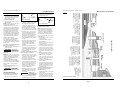
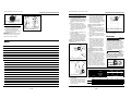
receptacle, as shown in Figure 1.
The green (or green and yellow)
conductor in the cord is the grounding wire. The motor must be securely and adequately grounded for
protection against shock.
Grounded
Pin
Figure 1
TEST
RESET
Grounded Outlet
20. Where a 2-prong is encountered,
replace the plug with a properly
grounded 3-prong receptacle in
accordance with the National
Electrical Code, local codes and ordinances. To ensure a proper ground,
the grounding means must be tested by a licensed or certified electrician.
21. Use only 3-wire extension cords that
have a 3-prong, ground type plug,
Deep Well Jet Pump
and 3-pole receptacles that accept
the equipment plug.
Do not handle
!
pump or pump
motor with wet hands, when standing
on a wet or damp surface or when
standing in water. Fatal electrical
shock could occur.
Pump motor is
equipped with an
automatic resetting thermal protector and
may restart unexpectedly. Protector tripping is an indication of motor overloading
because of operating pump at low heads
(low discharge restriction), excessively
high or low voltage, inadequate wiring,
incorrect motor connections or defective
motor or pump.
Pre-Installation
WATER SUPPLIES
The water supplies illustrated in Figure
15 are possible sources for water.
These water supplies can be divided
into two categories:
SURFACE WATER
Water from a lake, stream, pond and
cistern. This water is usually not fit for
human consumption, but may be suitable for washing, irrigation or other
household uses.
GROUND WATER
Water found in the water bearing stratum at various levels beneath the earth.
Of all the fresh water found on earth
only 3 percent is found on the surface
and 97 percent is underground.
TANKS - CONVENTIONAL STORAGE
The function of the tank is to store a
quantity of water under pressure.
When full, the tank contains approximately 2/3 water and 1/3 compressed
air. The compressed air forces the water
out of the tank when a faucet is
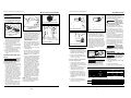
Bladder
2
3
Conventional
Tank
Precharged
Tank
5
Figure 2 - Conventional & Precharged
Storage Tanks
TANKS - PRECHARGED STORAGE
A precharged storage tank has a flexible
bladder or diaphragm that acts as a barrier
between the compressed air and water.
This barrier prevents the air from being
absorbed into the water and allows the
water to be acted on by compressed air at
initially higher than atmospheric pressures
(precharged). More usable water is provided than with a conventional type tank.
Precharged tanks are specified in terms of
a conventional tank. For example, a 20 gallon precharged tank will have the same
usable water or drawdown capacity as a
40 gallon conventional tank, but the tank
is smaller in size (Figure 2).
PRESSURE SWITCH
The pressure switch provides for automatic operation. The pump starts when
pressure drops to a cut-in setting. The
pump stops when pressure reaches a
cut-out setting.
Type
Air Volume
Control
Required
Well X
Precharged
PCA
Precharged
No
12P & 30 P Horizontal
Conventional
Yes
FX Horizontal
Precharged
No
4
6
7
1
opened. An air volume control automatically replaces air lost or absorbed
into the water. The usable water, or
drawdown capacity, of the tank is
approximately 1/6 of the tanks total
volume when operated on a “20-40”
pressure setting (Figure 2).
CHART 1 - JET PUMP/TANK ASSEMBLIES
2
Envíe su solicitud de repuestos a la siguiente direccion:
Wayne Water Systems
100 Production Drive
Harrison, OH 45030 U.S.A.
Sírvase proporcionar la suguiente información:
- Número de modelo
- Número de serie (si tiene)
- Descripción y número de repuesto como se muestra
en la lista de repuestos
DANGER
! WARNING
Modelos para pozos profundos
Para Piezas de Repuestos, Llame al 1-800-237-0987
Air Volume
Control
22. Use wire of adequate size to minimize voltage drop at the motor.
Manual de instrucciones de operación y piezas
9
8
10
12
13
No. de
Ref.
1
2
3
4
5
6
7
8
9
10
11
12
13
Descripción
Para Los Modelos
JCU75-3/4 HP
JCU100-1 HP
Ctd.
32059-001
16636-002
17145-001
17150-001
56393
56876
17148-001
67007-001
17149-001
41039-001
15766-002
23029-001
30010-001
32138-001
16636-002
17145-001
17150-001
56393
56875
17148-001
67007-001
17149-001
41039-001
15766-002
23029-001
30010-001
32138-001
16636-002
17145-001
17150-001
56393
56875
17148-001
67007-001
17149-001
41039-001
15766-002
23029-001
30010-001
1
4
1
1
1
1
1
2
1
1
2
1
1
56874-001
56874-001
56874-001
1
JCU50-1/2 HP
Motor
Tornillo
Plancha de sello
Empaquetadura cuadrada de caucho para anillo
Ensamblaje de sello del eje
Impulsor
Difusor
Tornillo
Anillo de cierre de caucho
Cubierta en espiral (Voluta)
3,2 mm (1/8”) Tap´ón de cebado (no se muestra)
Base
Presostato
Juego para reparaciones (incluyes No. 4, 5 y 9)
No
35 Sp