1
Crathco® Beverage Freezers
Operation and Instruction Manual
for
Models 5311, 5511, 5941, & 5711
TABLE
OF
CONTENTS
Warnings and Safety Precautions.....................3
Installation ...................................................4-6
Operating and Adjustments .......................6-11
Care and Cleaning ...................................12-17
Maintenance Service ................................17-21
Troubleshooting .......................................22-23
Exploded Views ........................................24-40
Electrical Diagrams ...................................41-52
Wiring Diagrams ......................................53-67
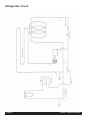
Refrigeration Diagrams.............................68-69
Prior authorization must be obtained from
Grindmaster Corporation for all warranty claims.
Model 5311
Grindmaster Corporation
4003 Collins Lane
Louisville, KY 40245 USA
(502) 425-4776
(800) 695-4500 (USA & Canada only)
FAX (502) 425-4664
www.grindmaster.com
© Grindmaster Corporation, 2000
PRINTED IN USA
0509 Form# WH-330-09
Part# W0600116
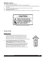
WARNING LABELS
OPERATOR'S SAFETY PRECAUTIONS
1)
Read and understand the operating instructions in this manual thoroughly.
2)
Note all warning labels on the freezer. If any of the warning labels are missing or damaged replace them
immediately.
3)
Do not wear loose fitting garments or jewelry which could cause a serious accident.
4)
Stay alert at all times during operation.
5)
Keep operating area clean.
6)
Do not operate freezer if any excessive noise or vibration occurs. Contact your authorized service agent.
Located on the right, left and rear panels.
INSTALLATION
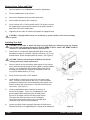
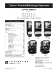
Shipment Transit
1)
The freezer has been operated and tested at the factory. Upon
arrival the complete freezer must be thoroughly checked for any
damage which may have occurred in transit. Note: A tip (N) Tell
warning device is placed on each shipping carton at the factory.
If the arrow tip is blue, the carton has been tipped in transit. (See Figure A)
2)
THE CARRIER IS RESPONSIBLE FOR ALL DAMAGE IN
TRANSIT WHETHER VISIBLE OR CONCEALED. DO NOT
PAY THE FREIGHT BILL until the freezer has been checked for
damage. Have the carrier note any visible damage on the freight bill.
If concealed damage and/or shortages are found later, advise the
carrier within 10 days and request inspection. The customer must
place any claim for damage and/or shortage with the carrier.
Grindmaster Corporation cannot make any claims against the carrier.
Crathco® 5000 Series Manual
Figure A
Page 3
Removal from Carton and Pallet
1)
Remove staples or cut cardboard box around the stapled area.
2)
Pull the cardboard box up off machine.
3)
Remove the Styrofoam packing and the plastic bag.
4)
Remove both side panels with screwdriver.
5)
Use a wratchet with a 3 inch extension and a 7/16 socket to remove
the shipping bolts (connecting the machine to the pallet) located on
both sides of the frame bottom plate.
6)
Supporting all four sides, lift machine up and place in appropriate area.
If equipped with spinner do not lift unit by spinner shaft to avoid serious damage
CAUTION:
to spinner.
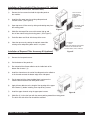
Installing Your Unit
CAUTION: Do not alter or deform the plug in any way! Altering or deforming plug may damage
unit and will void warranty! Receptacle required: NEMA 5-15R for model 5941, NEMA 5-20R for
model 5311, and NEMA 6-20R for models 5511 and 5711.
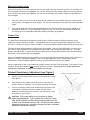
1)
Place freezer in a location that allows adequate space at each side
and above for proper air circulation. Minimum clearance is: 6” (15 cm)
on both sides 0” at back and open above the freezer. (See Figure B)
Failure to allow adequate ventilation will void the
CAUTION:
warranty and reduce freezer performance.
2)
Place the freezer on the self-sealing rubber pad on a level counter
that is stable and strong enough to safely support its weight (200lbs.)
(90.7kg), or if equipped with legs instead of pad, install legs by
screwing them into the four leg holes on the bottom of the unit.
(Leg Kit Part #W089.0220 (4) 4” Legs)
3)
Place On-Off-Clean switch in OFF position.
4)
Install header by removing two screws from the electrical box
cover. Carefully remove electrical box cover. Place the header
(transparency) between the clear and opaque plates (plastic lens).
Slip the electrical box cover back on to machine and reinsert the
four screws. (See Figure C)
5)
Install the standard one piece carb tube by placing it in
the hole in the hopper. If your unit is equipped with a two
piece smoothie/shake carb tube place the solid piece in
the hole in the hopper with the hole facing front to back.
Then place the carb tube sleeve over the solid piece,
lining up one of the holes with the hole in the solid piece.
(Select the larger hole for thickest products).
6)
Connect the power cord to a properly grounded 115V/20 Amp or
208-230V/20 Amp circuit (depending on the voltage of the dispenser).
Page 4
Figure B
Figure C
Crathco® 5000 Series Manual
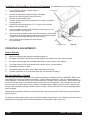
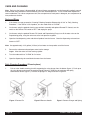
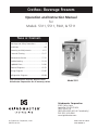
Installation of Concealed Air Filter Accessory Kit (optional)
(Part #s W089.0200 Stainless Steel, W089.0208 Black)
1)
Remove the four screws that hold the right side panel on
the machine.
2)
Install the filter panel over the existing side panel and
reinstall screws. (See Figure D)
3)
Open top cover of filter cover by raising and rotating away from
the existing panel.
INSTALL THE FILTER
PANEL OVER THE
EXISTING SIDE PANEL
& RE-INSTALL
SCREWS.
P/N: W0520101, COMES
IN KIT # W0890220
FILTER PANEL
Figure D
4)
Slide filter into top of filter cover with removal clip up and
the air flow arrows facing the existing panel. (See Figure E)
5)
Push filter down until flush with the top of the cover.
6)
Close the top cover by rotating the top back toward the
existing cover and pushing down once it is in place.
P/N: W0631805
FILTER
SLIDE THE FILTER IN BEHIND THE FILTER PANEL,
& IN FRONT OF THE EXISTING SIDE PANEL.
TO CHANGE REMOVE, CLEAN, & OR REPLACE.
Installation of Exposed Filter Accessory Kit (optional)
Figure E
(Part #W089.0206)
1)
Remove the four panel screws.
2)
Pull the bottom of the panel out.
3)
Run a bead of the silicone adhesive at the inside back of the
bottom filter channel. (2)
4)
Install the channel over the end of the side panel so the adhesive
in the channel contacts the bottom edge of the side panel.
5)
Put the panel with the channel added, back in place on the
machine and reinstall the two lower panel screws.
6)
Apply silicone adhesive to the length of the top edge of the upper
filter channel (1) before installing, then wipe off any excess.
7)
Install the upper channel using the upper panel screws.
8)
Slide filter (3) in from the front with the arrows pointing toward the existing panel.
The thick wire side of the filter should face outward.
Crathco® 5000 Series Manual
Figure G
Page 5
Installation of Spinner/Mixer Accessory Kit (optional)
(Part #W089.0053-115V) (Part # W0890124-220V)
1)
Turn to "off" and unplug the freezer from the
electrical power source.
2)
Remove the white plastic plugs covering the threaded
holes on the right front panel (facing the freezer).
3)
Remove the electrical box cover.
4)
Feed the spinner electrical wires through the 7/8” hole in the spinner
mounting bracket.
5)
Feed these wires up through the 1/4” x 1/2” hole in the right side
bottom of the electrical box.
6)
Secure the spinner to the front of the freezer with the long 1/4 x 20
screws provided. (See Figure H)
7)
Insert the screws through the front of the spinner bracket, then through
the spinner rear mounting bracket (making sure that the bracket flange
is toward the left facing toward the front of the freezer).
Spinner mounting bracket
See the spinner-wiring diagrams to locate spinner
wire connections.
Spinner
8)
Electrical box
Mounting screws
Figure H
OPERATING & ADJUSTMENTS
How to Operate:
1)
Sanitize unit following the cleaning instructions on page 12.
2)
Fill hopper with product. Allow barrel to fill with product to the proper level, then install carb tube.
3)
Turn power switch (toggle switch located underneath the electrical box) to "on" position.
4)
Turn mode switch (rocker switch located next to power switch) to freeze position.
5)
Allow product to freeze in barrel.
6)
To dispense product pull down valve handle and release when done.
7)
If product consistency is not as desired, adjust per the instructions on page 9.
Mix Considerations - General
Freezing characteristics are affected by the amount of sweeteners and solids in the mix, called BRIX. BRIX can be
measured with an instrument called a refractometer. A BRIX reading of between 11 and 14 will provide optimum
freezer operation. Mixes with this brix level will freeze down to a smooth, uniform consistency. Mixes with too high
a brix level will take longer to freeze down and will yield a soft, wet, frozen product. Mixes with too low a brix level
will have larger ice crystals and will have a tendency to dispense slowly. Note: Always take BRIX measurements
using mix that has been thoroughly blended, before it is frozen. Always allow frozen mix to thaw thoroughly before
taking a reading.
Alcohol content also affects product-freezing characteristics and may prevent the freezer from serving a product at
proper thickness.
For maximum output capacity always pre-chill mix before adding it to the freezer. Pre-chilled mix gives the freezer a
head start on the freezing process and will speed both initial freeze down and recovery time.
Page 6
Crathco® 5000 Series Manual
Carburetor Assembly
Your new freezer uses a metering device, known as a carburetor, to feed the proper ratio of mix and air into the
freezing cylinder. For products such as dairy based shake mixes, the proper mix to air ratio is generally accepted to
be two parts mix to one part air. This proportion yields a finished product that is both tasty and profitable. At this
ratio, one gallon of liquid mix will yield a volume of one and one-half gallons of frozen product.
The carburetor is a tube with a hole, or series of holes, bored through the side. It is located in the hopper and fits in
a hole that leads to the freezing cylinder. Air flows into the freezing cylinder through the top of the tube and mix
flows in through a smaller hole in the side of carburetor tube. The size of the mix inlet is balanced with the viscosity
(thickness) of the liquid mix and product draw rate, in such a way that the proper amount of mix is fed into the freezer cylinder to blend with air at just the right ratio. Mix viscosity varies by mix type, mix temperature, and mix age.
Different serving rates also demand different feed rates. The Crathco carburetor has an outer sleeve that can be
rotated to line up with different hole sizes to provide ideal overrun under all operating conditions.
You will need to experiment to determine how much mix to add to the freezing cylinder at start-up. This can be done
by watching the level of mix through the clear plastic dispensing valve when filling the hopper. When the correct
amount of mix feeds into the freezing cylinder install the carburetor tube in the "Off" position (outer sleeve set
between any two holes) and turn the freezer "ON" to freeze down to proper consistency.
Overrun
Overrun is the increase in product volume, expressed as a percentage, resulting from the entrapment of air in liquid
mix as it is frozen.
The rotating dasher blends air into the mix as it is frozen, resulting in increased product volume. For example, if one
gallon (4.4 liters) of liquid mix is poured into a freezer and one and a half gallons (6.6 liters) of frozen product is
drawn out, the result is a fifty percent volumetric increase, or a fifty (50%) percent “overrun”.
Why is overrun important? The introduction of air into the finished frozen product is essential from two
standpoints...taste and profitability. Frozen product with a low percentage of overrun costs more to serve, appears
wet, and is heavy. The introduction of air makes the finished frozen product taste richer. Too much air causes the
finished product to be too light and fluffy, making it less satisfying and adversely affecting sales. The optimum
percentage of overrun varies from one type of mix to another, but 50% overrun is a good average. The ingredients
in some mixes take on and hold air easier than others. Overrun also affects profitability. For example, an increase
from 25% to 50% overrun represents a mix savings of 17%.
Uniform overruns ensures consistent portion costs. If overrun is allowed to drop, it will cost more to serve a portion
of finished product.
Computing Overrun
1)
Weigh an empty cup.
2)
Weigh this cup filled to the top with liquid mix, and subtract the weight of the cup.
Note: Repeat this step only when changing mix sources, as mix weight will vary slightly from one supplier
to another.
Crathco® 5000 Series Manual
Page 7
Computing Overrun (cont.)
3)
Draw a heaping cup of frozen product that contains no air pockets. Note: Use a spatula or other device to
help fill the cup completely. Avoid tamping the cup as this artificially reduces overrun.
4)
Use a straight edge to scrape off excess product flush with the rim of the cup and weigh the cup.
5)
Subtract the cup weight and use the overrun formula to determine overrun.
Weight of
Weight of
Liquid Mix (Minus) Frozen Product x 100 = OVERRUN
Weight of Frozen Product
For Example:
If a full cup of liquid mix weighs 23 ounces (.652kg) and a full cup of frozen product weighs 15-1/2 ounces (.439kg),
then:
23-15 1/2 x 100 = 48.4% Overrun
15 1/2
Note: Several companies manufacture scales that automatically read out the overrun for one-pint samples. A
scale of this type is a valuable tool and should be part of any well run operation. A trick is to place the empty cup
on the scale and zero it out first; this will then automatically eliminate the weight of the cup from the calculation.
Overrun has a major impact on the size of the finished frozen portion. As the percentage of overrun (air in the
frozen product) increases, the size of the finished portion also increases, yet the portion weight remains the same.
For example, an increase from 25% to 50% overrun will yield a 20% larger portion. Customers equate size with
perceived value so proper overrun will result in increased customer satisfaction. Experiment with carburetor
settings to achieve optimum overrun and product quality with each mix. Some products such as Cappuccino taste
better with low overrun. Experiment with different carburetor settings to find the ideal combination for each product.
Use of Stand-By Switch
The "STAND-BY" switch allows the operator to retain optimum product quality and conserve energy during
extended non-draw periods. The "Stand-by" mode keeps the mix in the hopper at a safe storage temperature
and allows the product in the freezing cylinder to return to a refrigerated liquid state. Switching back to "ON"
quickly returns the product in the freezing cylinder to proper serving consistency.
At the start of the "STAND-BY" period:
1)
Select the "STAND-BY" mode by moving the mode switch to the middle position. The front panel
"STAND-BY" light will illuminate.
At the end of the "STAND-BY" period:
1)
Turn the switch to the "FREEZE" position by moving the mode switch. The "FREEZE" light will illuminate.
2)
When the freezer cycles off by reaching the desired temperatures you are ready to start serving.
IMPORTANT: The STAND-BY SWITCH should not be used in lieu of cleaning and
sanitizing procedures specified by local regulatory agencies.
Mix Low Function
This model will sense when the mix is low in the hopper. The mix low light will illuminate continuously for 2 minutes. After 2 minutes the light will begin to blink off and on for the next 8 minutes. The buzzer in the mix out circuit
is 2 minutes off and 5 seconds (or 5 beeps) on for a total of 10 minutes. At the end of the 10-minute time the
Page 8
Crathco® 5000 Series Manual
Mix Low Function (cont.)
buzzer is out of the circuit and the light will illuminate fully again. After the 10-minute cycle the mix out safety function is activated making the unit inoperable. The machine is placed into the standby mode to prevent any damage
to the machine from running dry of product. The unit can be reset back to the freeze mode by simply adding mix
into the hopper.
1)
If the unit is low in mix or the unit shuts down due to extended mix low condition (“Mix Low” safety function
has activated), refill hopper with fresh product. The unit will automatically revert back to its original operation
mode.
2)
If the mix low safety function has activated disabling the unit, and the product has not been added for an
extended period of time - verify the product is okay for re-use. If it is not, use fresh product to restart the
unit. Empty the unit of old product and follow sanitizing and start up procedures.
Product Tips
The 5000 Series was designed to dispense a wide variety of frozen beverages including smoothies, frozen
cappuccino, shakes and frozen cocktails. These products can be served in consistencies ranging from thin to
fairly thick. For optimum long-term freezer reliability, it is recommended that product thickness not be set too thick.
Two types of white plastic dispensing valve plungers are available. One style, part W048.0462, is used to serve
these thin to medium products such as cappuccino and cocktails and has one horizontal outlet slot. The other
plunger, part W048.0463, is used to serve thicker product such as shakes and smoothies and has two horizontal
outlet slots. These plungers are interchangeable.
Over an extended period of time some products, such as frozen cocktails that contain alcohol, have a tendency to
separate, or stratify. Separation of product in the mix storage hopper can result in frozen product quality
inconsistency. Simply keeping the product stirred on a regular basis will eliminate this problem.
Some of cappuccino or latte' mixes contain dairy products which can spoil if not refrigerated. If the freezer is to be
turned off at night these products must be removed from the freezer. Contact your local health department
regarding its regulations for proper mix handling and storage.
Product Consistency Adjustment (see Figure I)
1)
Remove the front electrical box cover by removing the two screws.
(See figure C).
2)
If the product in the cylinder has been frozen for more than 30
minutes, draw out 16 ounces (1/2 liter) before checking consistency.
3)
Turn the consistency control knob, located at the top center of the
circuit board, clockwise to achieve a colder setting or thicker
product or counter-clockwise to achieve a less cold setting or less
thick product. (See Figure I).
This control setting is very sensitive so always
CAUTION:
make small adjustments. If you visualize this control as a clock
face, with the adjuster set all the way counter-clockwise it would
be 5:00. A recommended setting is 7:00. This would be the warmest
setting the machine has. A one-hour change will make a noticeable
difference in product consistency.
Crathco® 5000 Series Manual
Location of electronic control board
Figure C
Page 9
Product Consistency Adjustment (cont.)
4)
When making adjustments to a thicker (colder) setting, dispense approximately 16 ounces (1/2 liter) of
product and recheck consistency after the compressor has cycled off.
5)
If the consistency is still not correct, repeat steps 2 and 3.
"Standby" - Freezing Cylinder Temperature Adjustment
1)
Remove the front electrical box cover. (See Figure C).
2)
For a colder setting, turn the "Barrel" control adjuster, located at the top left of the circuit board, counter
clockwise. (See Figure I).
This control setting is very sensitive so always make small adjustments. If you visualize
CAUTION:
this control as a clock face, a one-hour change will make noticeable difference in freezing cylinder
product temperature. A recommended setting is 11:00.
Hopper Temperature Adjustment
1)
Remove the front electrical box cover.
2)
For a colder setting, turn the "Hopper" control adjuster, located at the top left of the circuit board, counter
clockwise. (See Figure I).
This control setting is very sensitive so always make small adjustments. If you visualize
CAUTION:
this control as a clock face, a one-hour change will make a noticeable difference in hopper product
temperature. A recommended setting is 10:00.
Note: Some models will have a built in feature (in the freeze mode) that will make the machine inoperable if
the mix gets low and is not refilled after ten minutes. (The normal sequence is five beeps every two minutes
for a total of ten minutes, then shut down occurs until the unit is refilled). These same units will also have a
forty-five second dasher run time after the compressor turns off.
Consistency Control - Overview
CAUTION: SHOCK HAZARD
THIS ADJUSTMENT REQUIRES REMOVAL OF THE ELECTRICAL BOX COVER AND SHOULD BE
MADE BY A QUALIFIED SERVICE TECHNICIAN.
The “freeze” mode consistency setting adjusts the frozen product thickness. In the “freeze” mode, as the liquid mix
in the cylinder freezes, it becomes harder for the motor to turn the dasher assembly. The control board senses the
amount of energy that the drive motor consumes as it rotates the dasher assembly through the product in the cylinder. The control board will turn the compressor and barrel solenoid valve off at the proper consistency. The drive
motor will continue to run for 45 seconds after the compressor is cycled off. This is called the blending cycle. After
the blending cycle is complete the drive motor also is shut off. The drive motor and compressor will run together at
any time refrigeration is required in the barrel. The compressor will run independently for the hopper if required.
The hopper is controlled by temperature. The thermistor will signal the board and the board will start the compressor and open the hopper solenoid valve.
The unit will remain off until either the timer in the control board (either 10 or 15 minutes dependent upon which
value is selected) restarts the drive motor. In this case the drive motor will run for 45 seconds and if no refrigeration
is required the drive motor will then shut off. If refrigeration in the barrel is required the freeze cycle is repeated as
well as the blending cycle. The unit will also restart the drive motor if the plunger is raised. The plunger switch will
start the drive motor and remain on as long as it is held open. After the plunger is closed, the drive motor will continue to run for 45 seconds. The compressor will start, and barrel solenoid valve will open. If refrigeration is
required during this time the freeze cycle and blend cycle will follow.
Page 10
Crathco® 5000 Series Manual
Consistency Control - Overview (cont.)
In the “standby” mode the control board senses the temperature of the product in the barrel. The drive motor is
cycled on time only. It will operate for 2 minutes ON then 18 minutes OFF as long as it is in “standby”. The compressor and drive motor are cycled independently for the barrel in the “standby” mode. Once the barrel thermistor
signals to the board, the board will start the compressor and the barrel solenoid valve will open as refrigeration is
required. It will continue to run until satisfied. The plunger switch is disabled and the drive motor will not start when
the plunger is opened. The hopper is still controlled by temperature. If the thermistor signals a raise in temperature
the compressor will start and the hopper solenoid valve will be opened. It will continue to run until satisfied.
In the “clean” mode the drive motor will run continuously. (The compressor will not run in the “clean” mode.) This is
for emptying out product for cleaning purposes.
There are eleven (11) lights on the circuit board that indicate the following: (See Figure I)
BARREL (D1) - Illuminated when the freezing cylinder (barrel) has achieved the pre-set temperature in the
"Standby" mode.
HOPPER (D2) - Illuminated when the hopper has achieved the pre-set temperature in the "Standby" mode.
WASH (D3) - Illuminated when the mode switch is in the wash or "Clean" position.
FREEZE (D4) - Illuminated when the mode switch is in the "Freeze" mode.
DISPENSE (D5) - Illuminated when the dispensing valve is open calling for both the compressor and drive
motor to operate.
GREEN CONSISTENCY (D6) - Off when the motor and compressor are off. Illuminated when the
compressor and dasher are bringing product to preset consistency. Blinks as preset consistency is
achieved and then goes out.
RED CONSISTENCY (D7) - Blinks as preset product consistency is approached. Glows steadily when
preset consistency is achieved and then goes out.
COIL (D8) - Compressor contactor energized
COIL (D9) - Drive motor coil energized
COIL (D10) - Hopper refrigeration solenoid coil energized
COIL (D11) - Freezing cylinder refrigeration solenoid coil energized
Figure I Electronic Control Board
Crathco® 5000 Series Manual
Page 11
CARE AND CLEANING
Note: Each time the freezer is disassembled, all internal freezer components must be thoroughly washed, scoured,
and sanitized using procedures recommended by your local health department. In lieu of local health department
recommendations, use a three compartment sink; one compartment to wash parts in detergent, one compartment to
rinse, and one to sanitize.
Drain and Rinse
1.
If the freezer is empty, proceed to “Cleaning Following Complete Disassembly of Unit” or “Daily Cleaning
Procedure”. If the freezer is full of product, turn the mode switch to "CLEAN".
2.
On freezers using the optional electric pump and tank assembly and optional Remote Fill Control, turn the
switch on the Remote Fill Control to "OFF" and unplug the pump.
3.
On freezers using the optional Remote Fill Control and Proportioning Pump, turn off the water valve on the
Proportioning pump, using the valve next to the inlet pressure regulator.
4.
Open the front dispensing valve and drain all product from the freezer. Close the dispensing valve and turn
freezer to "OFF".
Note: Use approximately 2-1/2 gallons (10 liters) of cool water to rinse product out of the freezer.
5.
Remove the carburetor tube and pour water into the storage
hopper. Allow the water to fill the freezing cylinder.
6.
Turn the mode switch to "CLEAN" for 5 minutes.
7.
Open the dispensing valve and drain the water from the freezer.
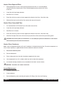
Daily Cleaning Procedure (Clean-in-place)
1.
Pull out valve handle retaining pin while supporting the valve plunger from the bottom (figure J). Push up on
the valve plunger and remove the stainless handle (figure K). Slide the valve plunger and spring
downward to remove (figure L). Remove the plunger “O” Rings as shown in figure M.
Figure J Remove Pin
Page 12
Figure K Remove Handle
Figure L Remove Plunger and Spring
Crathco® 5000 Series Manual
Daily Cleaning Procedure (cont.)
Note: The best way to remove an “O” Ring is to first wipe off all of the lubricant
using a clean paper towel. Pinch the “O” Ring upward with a dry towel between
your index finger and thumb. When a loop is formed in the “O” Ring, roll it out
of the groove with your other thumb. Always remove the “O” Ring farthest from
the end of the plunger first. (See figure M).
2.
Take all components to the cleaning area.
3.
Carefully inspect the “O” Rings and replace if necessary.
Figure M Ring Removal
Cleaning Carburetor, Dispensing Valve and Plunger Assembly
1.
Prepare 1 gallon solution of hot tap water and a good grade of
dish washing detergent.
2.
Thoroughly wash valve plunger, spring, carburetor assembly and all
“O” Rings in detergent solution.
3.
Using medium sized brush (supplied with freezer) clean the
bottom of the valve body and the inside of the plunger bore with
detergent solution taking care to remove all remaining lubricant
(figure N).
Figure N Clean Valve Body
Sanitizing Carburetor and Valve Components
1.
Re-assemble carburetor assembly installing the two “O” Rings at the
bottom of the carb tube.
2.
Place the carburetor assembly in the bottom of the hopper.
3.
Replace “O” Rings on valve plunger and lay plunger assembly on a
clean piece of paper towel.
4.
Prepare a minimum of 4 gallons (15 liters) of sanitizing solution (Stera
Sheen Green Label or equivalent) following the manufacturer’s
instructions.
Note: Add 4 ounces of Stera Sheen to 4 gallons (15 liters) of 120° Fahrenheit
(50° Centigrade) water to achieve a concentration of 100 parts per million.
5.
Dip the medium sized brush (supplied) into the sanitizing solution and
sanitize the inside bore of the dispensing valve (figure O).
6.
Place a small amount of sanitary lubricant onto a piece of clean paper
toweling (figure P).
7.
Use a clean piece of paper toweling to pick up the small end of the valve
plunger assembly. Apply the lubricant on the other piece of paper
toweling to the “O” Rings on the valve plunger assembly (figure P).
Figure O Sanitize Valve Body
Figure P Lubricate Plunger
Crathco® 5000 Series Manual
Page 13
Sanitizing Carburetor and Valve Components (cont.)
8.
Slide the valve plunger spring over the small end of the valve
plunger and, using another clean piece of paper toweling, pick up the
valve plunger at the outlet end and insert plunger and spring into the
valve body (figure Q).
9.
Push up on the valve plunger and insert the stainless steel handle
(figure R).
Figure Q Installing Plunger and Spring
10.
Insert the dispensing valve handle retaining pin (figure S)
Sanitizing and Refilling
1.
Pour sanitizing solution into the mix storage hopper and allow the
solution to fill freezing cylinder. Use a large brush (supplied) to
sanitize all hopper surfaces (figure T).
2.
Turn panel switch to “CLEAN” and allow freezer to run for 20
minutes.
3.
Open dispensing valve and drain solution. Allow the auger to push
remaining sanitizer out of the freezing cylinder.
4.
Place a small amount of sanitary lubricant onto another piece of
clean paper toweling (figure U).
5.
Use a clean piece of paper toweling to pick up the large end of the
carburetor from the bottom of the hopper taking care not to touch the
sanitized carburetor with your bare hands.
6.
Apply the lubricant on the other piece of paper toweling to the two “O”
Rings on the bottom of the carburetor assembly (figure U).
7.
Place the lubricated carburetor assembly on a clean piece of paper
toweling.
Figure R Insert Valve Handle
Figure S Insert Retaining Pin
Figure T Sanitize Hopper
8.
Use either fresh product or mix new product according to
manufacturer’s instructions.
9.
Fill mix storage hopper with product.
10.
Open dispensing valve. Pour product into the hopper and allow this
product to chase out any remaining sanitizer.
Figure U Lubricate Carb Tube
Page 14
Crathco® 5000 Series Manual
Sanitizing and Refilling (cont.)
11.
Watch the product flowing out of the dispensing valve and close the
valve when the sanitizer remaining in the cylinder has been purged
by the new mix.
12.
Use a clean piece of paper toweling to insert the sanitized carburetor
assembly into the inlet hole in the hopper (figure V).
13.
Fill mix storage hopper with fresh product.
14.
Turn front panel switch to “ON”. Allow approximately 20 to 30 minutes
for the freezer to reach proper consistency.
Figure V Carb Tube
Cleaning Following Complete Disassembly of Unit
1.
Remove knobs and carefully remove the front dispensing
valve assembly.
2.
Disassemble the dispensing valve assembly by removing the
retaining pin, pushing up on the plunger assembly and pulling
out the handle. This will allow the plunger assembly, complete
with O-Rings, to be removed as a unit. Remove the spring.
Remove the O-Rings from the plunger assembly and back
of the dispensing valve body. (See Figure W.)
Figure W Exploded View of Dispensing Valve
Note: The best way to remove an O-Ring is to first wipe off all of the lubricant using a clean paper towel. Pinch the O-Ring upward with a dry towel
between your index finger and thumb. When a loop is formed in the O-Ring,
roll it out of the groove with your other thumb. Always remove the O-Ring farthest from the end of the plunger first. (See Figure X).
Note: Carefully inspect the O-Rings and replace if necessary.
3.
Remove the dasher assembly taking care to avoid damaging the rear
seal assembly at the back of the freezing cylinder.
4.
Remove stationary portion of the shaft seal assembly from the back end
of the freezer cylinder. This is accomplished by reaching into the cylinder
and pulling seal out with your index finger. (See Figure Y)
5.
Slide the rotary seal off the the auger shaft. Inspect both seal components carefully for nicks or cracks.
Replace seal if defective.
Figure X O-Ring Removal
Note: To prevent leakage, both surfaces of the seal must be smooth with no
chips or cracks. Wash all components in a detergent solution, sanitize and
allow to air dry.
Figure Y Remove Stationary part of seal
Crathco® 5000 Series Manual
Page 15
Cleaning Following Complete Disassembly of Unit (cont.)
IMPORTANT: After disassembly, thoroughly scour each part of the freezer in a warm mild detergent
solution including the inside of the freezing cylinder and the mix storage hopper. Rinse each part with
clear water. Prepare a minimum of 3-1/2 gallons (13 liters) of sanitizing solution (Divorsol CX or equivalent) following the manufacturer's instructions.
Note: Add 3 ounces (85.4 mg) of Divorsol CX to 3-1/2 gallons (13
liters) of 120° Fahrenheit (50° Centigrade) water to achieve a
concentration of 200 parts per million. Dip or wipe each part
in sanitizing solution and allow them to dry on clean paper toweling.
Reassembly
Figure Z Reassemble rotary
portion of seal as shown
1.
Wet the inner rubber lip of the rotary portion of the seal and the
back end of the auger shaft with water. Slide rotary portion of
assembly onto the auger shaft, RUBBER FIRST, with the smooth
sealing surface toward the back of the auger. (See Figure Z)
2.
Insert the stationary portion of the seal into the grooved rubber boot with
the polished surface facing out (forward). Lubricate the grooved exterior
portion of the boot and insert it straight back into recess at the
Figure AA Installing the stationary
back of the freezing cylinder, RUBBER FIRST.
portion seal
(See Figure AA & BB)
Note: If the circular portion of the seal is white, make sure that the
groove is toward the rubber (back of freezer).
3.
Reassemble the dasher assembly, as shown in Figure CC. Insert
the larger front and smaller rear white plastic bearings into
Figure BB Seal Assembly installed correctly
dasher, then slip in the stator rod. Attach scraper blades.
Carefully and slowly guide the auger into the freezing cylinder
taking care not to damage the seal assembly. Turn auger shaft
until it engages the square drive coupling.
4.
Reassemble the dispensing valve assembly as shown in Figure DD.
Thoroughly wash and sanitize all components, lubricate the inside
bore of valve body with a thin film of food grade sanitary lubricant.
Reinstall the O-Rings on the plunger assembly and lubricate the
entire plunger. Reassemble the valve and replace the retainer pin.
Inspect and lubricate the large O-Ring and refit it into the rear of
the valve assembly. Install the valve assembly on the front studs
and tighten knobs until they are finger tight.
Do not use tools to tighten knobs.
Figure CC
Figure DD
Page 16
Crathco® 5000 Series Manual
Reassembly (cont.)
5.
Disassemble the carburetor assembly and remove the O-Rings.
Wash and sanitize all parts.
6.
Reinstall and lubricate the O-Rings and slip on the outer tube if equipped. (See Figure EE)
Figure EE
Thick product
carb tube
Standard
carb tube
Low overrun
carb tube
Sanitizing and Refilling
1.
Prepare a minimum of 3-1/2 gallons (13 liters) of sanitizing solution (Divorsol CX or equivalent) following the
manufacturer's instructions.
Note: Add sanitizer to 3-1/2 gallons of water (warm) to achieve a concentration of 200 parts per million.
2.
Pour sanitizing solution into the mix storage hopper and allow the solution to fill freezing cylinder. Use a
brush to clean the hopper sides and bottom.
3.
Turn panel switch to "CLEAN" and allow freezer to run for 5 minutes.
4.
Open dispensing valve and drain solution. Turn freezer to "CLEAN" for a few seconds to allow the auger to
push remaining sanitizer out of the freezing cylinder.
5.
If you are using a concentrated product, mix the product according to the manufacturer's instructions.
6.
Open dispensing valve. Pour product into the hopper and allow this product to chase out any remaining
sanitizer. Watch the product flowing out of the dispensing valve and close the valve when the new mix
has purged the sanitizer remaining in the cylinder.
7.
Sanitize and install the carburetor. (Figure R). Refill mix hopper.
8.
Turn front panel switch to "ON". Allow approximately 20 to 30 minutes for the freezer to reach proper
consistency.
MAINTENANCE
Suggested Weekly Maintenance
1.
Clean, lubricate and sanitize the freezer following guidelines in (Care and Cleaning).
2.
Clean the exterior of the freezer using a soft wet cloth.
Crathco® 5000 Series Manual
Page 17
How to Clean Exposed Filter:
1.
Slide exposed filter out of the rails by pulling forward on the filter. It is recommended to
remove the filter by using the palm of your hand and applying even pressure to the face
of the filter.
2.
Clean filter with liquid soap and water.
3.
Soak filter for 15 minutes.
4.
Rinse filter with heavy stream of water, opposite the direction of air flow. Allow filter to dry.
5.
Slide the filter into the rails until the filter contacts the stop on the top rail.
How to Clean Concealed Filter:
1.
For concealed filters lift lid and pull up on filter tab to remove filter.
2.
Clean filter with liquid soap and water.
3.
Soak filter for 15 minutes.
4.
Rinse filter with heavy stream of water, opposite the direction of air flow. Allow filter to dry.
5.
Slide filter into top of filter cover with removal clip up and the air flow arrows facing the existing panel.
CAUTION: Disconnect power for maintenance. Do not attempt to perform maintenance on the freezer
until electrical power has been disconnected.
How to Clean Condenser
Note: Loss of refrigeration efficiency will result if condenser is allowed to become dirty. Excessive compressor run
time or loss of capacity is a good indication that the condenser needs to be cleaned.
1)
Disconnect electrical power.
2)
Remove side panels.
3)
Place a damp towel over the side of condenser opposite the fan motor.
4)
Use compressed air or CO2 to blow out dirt from the fan side of the condenser.
5)
An alternate cleaning method is to use a condenser brush and a vacuum cleaner.
CAUTION: Procedure can create a loud noise.
Annual Maintenance
1.
Disconnect electrical power.
2.
Clean condenser.
3.
Remove dispensing valve assembly and replace all O-Rings. (See Care and Cleaning).
Page 18
Crathco® 5000 Series Manual
Annual Maintenance (cont.)
4.
Remove dasher assembly, inspect stator bearings and replace shaft seal set. (See Care and Cleaning).
5.
Remove rear panel and inspect "V" belt.
6.
Inspect the drive shaft square hole for wear (rounding-out).
7.
Check drive shaft and motor shaft bearings for excessive wear.
8.
Reinstall side and back panels.
9.
Re-connect power supply.
Belt Adjustment
CAUTION: Unplug the machine before performing any adjustments. This procedure
must be done by a qualified technician.
Check the belt tension. The proper belt deflection is 1/2" overall. If the deflection is more than 1/2" the motor will
need to be lowered. If the deflection is less than 1/2" the motor will need to be raised. Follow this procedure to
adjust the motor to achieve proper belt tension.
1)
Unplug the machine and remove both side and the rear
panels.
2)
Locate the motor flange bearings (#W038.0009). These
are the pillow block bearings that hold the motor to the
cradle. The motor is double shafted and the shaft extends
through a bearing on each end. The bearing is held to the
motor cradle by two allen bolts on each bearing.
3)
Loosen the allen bolts on each bearing. Do not loosen the
set screws that hold the bearing collar to the motor shaft.
4)
Lower the motor or raise the motor as needed. The motor
must be kept level from front to back. Do not lower or
raise only one end of the motor. This will result in excessive belt wear and belt noise.
5)
Tighten all four allen bolts down. Align the motor pulley with the top pulley if needed.
6)
The motor pulley should be in alignment with the large (driven) top pulley. Use a straight edge along the
top pulley.
7)
If the pulleys are not in alignment, remove the setscrew from the motor pulley and move either in or out as
needed.
8)
Reinstall the setscrew. Use non-permanent loc-tite on the setscrew and tighten it back down on the motor
shaft. Be sure the setscrew is tightened down flat on the motor shaft.
9)
Return the unit back to service.
Crathco® 5000 Series Manual
Page 19
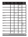
5000 SERIES FREEZER SPECIFICATIONS:
Specification
Model 5311
Model 5511
Model 5711
Model 5941
Circuit NEMA#
NEMA 5-20R
NEMA 6-20R
NEMA 6-20R
NEMA 5-15R
Electrical
115 volt, 60 Hz, 1 Phase
Dedicated 20 Amp circuit
208/230 volt, 60 Hz, 1
Phase
Dedicated 20 Amp circuit
208/230 volt, 60 Hz,
1 Phase
115 volt, 60 Hz, 1 Phase
15 Amp circuit
Drive Motor
1/4 hp, Capacitor Start/Run 1/2 hp, Capacitor Start/Run 1/2 hp, Capacitor Start/Run 1/4 hp, Capacitor Start/Run
N/A
Note: Freezer must be
connected to a separate
condensing unit.
Compressor
3/4 hp
1 hp
1-1/2 hp
Cooling
Air Cooled
(Optional Water Cooled)
Air Cooled
Air Cooled
N/A
Actual Weight
175 lbs. (79.4 kg)
185 lbs. (84 kg)
260 lbs. (97 kg)
140 lbs. (63.5 kg)
Mix Hopper Capacity
5 gallons (18.9 liters)
5 gallons (18.9 liters)
5 gallons (18.9 liters)
5 gallons (18.9 liters)
Freezing Cylinder
Capacity
1-1/2 gallons (5.7 liters)
1-1/2 gallons (5.7 liters)
1-1/2 gallons (5.7 liters)
1-1/2 gallons (5.7 liters)
Refrigerant
See Serial Number Plate
See Serial Number Plate
See Serial Number Plate
See Serial Number Plate
Refrigerant Charge
See Serial Number Plate
See Serial Number Plate
See Serial Number Plate
See Serial Number Plate
High Side
(approximate operating
pressure)
275 to 350 psi
(19 to 25 k/cm)
275 to 350 psi
(19 to 25 k/cm)
275 to 350 psi
(19 to 25 k/cm)
240 to 270 psig
(ambient dependent)
Low Side
(approximate operating
pressure)
35 (w/ standard) to
40 psig
45 (w/ scraper blade auger)
(w/ scraper blade auger)
psi (2.5 to 3 k/cm)
32 to 40 psig
32 to 38 psig
(load dependent)
High Side Design
Pressure
420 psig
460 psig
331 psig
420 psig
Low Side Design
Pressure
174 psig
174 psig
174 psig
174 psig
Specifications are subject to improvement or change without notice.
Page 20
Crathco® 5000 Series Manual
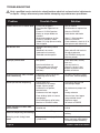
Part
Description
Monthly
Every
3 Months
Every
6 Months
Shaft seal
Drive shaft
Drive belts
Scraper blades
on dasher
Annually
Quantities
to be
Replaced
Inspect &
replace if
necessary
1
Inspect &
replace if
necessary
1
Inspect &
replace if
necessary
1
Inspect &
replace if
necessary
2
Square cut
o-ring on valve
body/face plate
Inspect &
replace if
necessary
1
Front stator
flange bearing
Inspect &
replace if
necessary
1
Inspect &
replace if
necessary
1
Rear stator
flange bearing
Dispense valve
o-rings
X
Thick Product
plunger:2
Standard Product
plunger:3
X
2 or 3
Carb tube o-rings
Cleaning brush
Condenser
Inspect &
replace if
necessary
Inspect &
clean if
necessary
Maximum
1
Maximum
1
Refer to the Crathco Parts Price List when ordering the above parts
Crathco® 5000 Series Manual
Page 21
TROUBLESHOOTING
a qualified service technician should perform electrical and mechanical adjustments
Only
or repairs. Always disconnect power before attempting any maintenance procedures.
Problem
Freezer will not run or freeze down
Product too soft
Improper product taste
Possible Cause
Solution
• Freezer not plugged in
• Circuit breaker tripped or fuse
blown
• Freezer in "CLEAN" position
• Dasher or scraper blades not
installed
• Obstructed condenser air flow
• Freezer in "Stand-by" mode
• (Model 5511) High pressure safety
switch tripped.
• Plug in machine
• Reset breaker or replace fuse
• Improper consistency control
setting
• Mixed soft, no overrun
• Carburetor set incorrectly
• Extended non-draw period
• Re-adjust consistency control
• Mix spoiled
• Check date code, use only
fresh mix
• Use only fresh mix
• Draw out 1 quart (1 liter),
dispose of product. Allow
product to refreeze
• Used rerun/leftover mix
• Frozen product too fluffy and
icy (Product frozen too long,
low draw)
• Switch to "FREEZE"
• Install dasher and blades
• Allow 6” (15cm) on sides
• Switch to "FREEZE"
• Clean condenser, check for 6" air
clearance on each side of unit
• Drain and refill with fresh mix
• Re-adjust carburetor
• Use STANDBY during slow
business periods
Frozen product too stiff, or freezer
runs continuously
• Consistency control set too firm
• Dispensing valve not fully
closed
• Re-adjust consistency control
• Close valve, lubricate properly
Frozen product not dispensing
• Power switch OFF
• Insufficient mix in storage
hopper, light on, beeper
• Carburetor in off position,
between holes
• Carburetor inlet hole clogged
• Turn Power Switch to ON
• Refill storage hopper
• Foam buildup, liquid mix cannot
feed properly
• Drive belt broken or off of pulley
• Machine in STAND-BY mode
• Remove foam from hopper
using sanitized utensil
• Replace or repair
• Set switch to FREEZE
• Worn, defective or improperly
installed seal
• Replace and lubricate per
manual
Liquid coming out of drain tube,
front of freezer
Excessive dispensing valve leakage • Worn or defective O-Rings
Scraping sound during freeze
down
Page 22
• Frozen product scraping off of
cylinder walls
• Set carburetor to proper hole
size
• Unclog carburetor
• Replace and lubricate at each
cleaning
• Normal sound during freeze
down, goes away when product
is frozen to proper consistency
Crathco® 5000 Series Manual
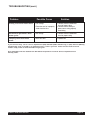
TROUBLESHOOTING (cont.)
Problem
Clicking sound from electrical box
Possible Cause
• Low voltage
• Extension cord or improperly
sized electrical wire
Solution
• Connect freezer to dedicated
circuit of proper rating
• Connect freezer directly to
power source using properly
sized wiring
Merchandiser light flickers when
freezer cycles
• Low voltage
• Connect freezer to dedicated
circuit or proper rating
Thumping sound from inside
freezer
• Worn drive belt
• Replace belt
If you still need help, call our service department at (800) 695-4500 (USA & Canada only) or (502) 425-4776 (Monday
through Friday, 8 am - 6 pm EST) or an authorized service center in your area. Please have the model and serial
numbers ready so that accurate information may be given.
Prior authorization must be obtained from Grindmaster Corporation’s Technical Services Department for all
warranty claims.
Crathco® 5000 Series Manual
Page 23
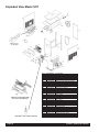
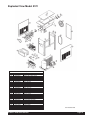
Exploded View Model 5311
Optional Dasher
Part #0430026
Optional X-large drip pan
for units with spinners
Optional Thick Product plunger
Page 24
Item
Part Number
1
5
10
22
23
25
27
30
32
33
34
35
36
37
38
39
44
48
49
58
61
100
107
120
121
137
138
139
140
141
142
W0110002
W0210171
W0520063
W0520064
W0520065
W0340022
W0340058
W0340210
W0389001
W0430024
W0430028
W0430032
W0430089
W0450008
W0450209
W0451067
W0520094
W0480445
W0480450
W0572286
W0572340
W0630711
W0650913
W0212081
W1431084
W0472064
W0472063
W0472062
W0631631
W0631632
W0670007
Description
Valve Stud
Frame Assembly
Stainless Steel Rear Panel
Stainless Steel Side Panel Left
Stainless Steel Side panel Right
213 O-Ring
Barrel Gasket
Seal Set Standard
Modified Flange Bearing
Blind Flange Bearing
Stator Rod Weldment
Stator Flange Bearing
Scraper Dasher
Pulley (10 inch)
Drive V-Belt
Drive Shaft
Hopper Cover Black
Valve Handle
Valve Body
Electrical Box Cover
Electrical Box Assembly
Valve Knob
Circuit Board
Base Assembly
Scraper Blade
Drip Pan Bracket
Drip Pan Insert
Drip Pan Form
Plastic Drip Pan (white)
Plastic Drip Pan (black)
Sound Insulation
Crathco® 5000 Series Manual
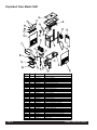
Exploded View Model 5511
Item
1
5
10
22
23
27
30
32
33
34
35
36
37
38
39
44
45
46
47
48
49
58
61
100
107
120
121
136
137
138
Part Number
Description
W0110002
W0210171
W0520063
W0520064
W0520065
W0340058
W0340210
W0380025
W0430024
W0430028
W0430032
W0430089
W0450053
W0450209
W0451067
W0520094
W0472062
W0472063
W0631632
W0480445
W0480450
W0572452
W0572454
W0630711
W0650913
W0212000
W1431084
W0201335
W0570617
W0570619
Valve Stud
Frame Assembly
Stainless Steel Rear Panel
Stainless Steel Side Panel Left
Stainless Steel Side Panel Right
Barrel Gasket
Shaft Seal Set
Flange Bearing
Blind Flange Bearing
Stator Weldment
Stator Flange Bearing
Scraper Dasher
Pulley (10 inch)
V-Belt
Slush Drive Shaft
Hopper Cover, Black
Drip Pan Bkt For X-LG
Drip Pan Insert
Plastic Drip Pan Black
Valve Handle
Valve Body
Electrical Box Cover
Electrical Box Assembly
Valve Knobs
Circuit Board
Base Assembly Shake Machine
Scraper Blade
Evaporator Assembly
Run Capacitor
Start Capacitor
Crathco® 5000 Series Manual
5511-0109-015-3-20-00
Page 25
Exploded View Model 5941
5941 EXPLODED VIEW
8
27
24
3
4
26
6
25
23
20
9
21
4
19
10
13
2
7
14
15
17
31
36
35
30
1
29
32
28
33
22
35
ITEM
NO.
1
2
3
4
6
7
8
9
10
13
14
15
17
19
20
21
22
23
24
25
26
27
28
29
30
31
32
33
34
35
36
Page 26
QTY.
1
1
1
4
1
1
1
1
1
1
1
1
1
1
1
1
1
1
2
1
1
1
3
1
1
1
1
1
2
1
4
PART NUMBER
DESCRIPTION
W0210257
W0211232
W0201346
W0110013
W0450053
W0450209
W0520094
W0340201
W0572458
W0572452
W0480450
W0340055
W0480445
W0340058
W0520097
W0520107
W0520065
W0430089
W1431084
W0430028
W0430032
W0430024
W0340022
W0472062
W0631632
W0472074
W0472064
W0480462
W0470015
W0210258
W0630711
BASE ASSEMBLY
FRAME ASSEMBLY
EVAPAORATOR ASSY, 5311 & 5511
STUD, VALVE NEW STYLE
PULLEY, 10" W/ 1" BORE
V-BELT 3L460 X 3/8" FHP
Hopper Cover Single
Shaft Seal Set
Electrical Box Assy. 5941
Electrical Box Cover
Valve Body
Valve Square Cut O-Ring
VALVE HANDLE
Barrell Gasket
Panel, Rear 5941
Left Side Panel
Right Side Panel
Dasher, Scraper
Scraper Blade, New Style
STATOR WELDMENT PICKLED
STATOR FLANGE BEARING
REAR STATOR BEARING
Plunger O'Rings
Pan,Drip Form X-LG
Drip Tray
Insert, Drip Pan
Drip Pan Bracket
Plunger, Standard Product 5000
Spinner, DMC180
SPINNER BRKT ASSEMBLY, LEFT
Valve Knob
Crathco® 5000 Series Manual
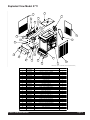
Exploded View Model 5711
),/(1$0(&)%%6/''5:6+([SORGHG9LHZ
3$57
,7(012
180%(5
:
:
:
:
:
:
:
:
:
:
:
:
:
:
:
:
:
:
:
:
:
:
:
:
:
:
:
:
:
Crathco® 5000 Series Manual
7LWOH
6WRFN$VV\
38//(<:%25(
%HOW9
9DOYH%RG\
%DUUHOO*DVNHW
9DOYH6TXDUH&XW25LQJ
)DV3LQ9DOYH
9DOYH.QRE
9DOYH+DQGOH
3/81*(567'352'6(5,(6
3OXQJHU2
5LQJV
9DOYH6SULQJ
678'9$/9(1(:67</(
)URQW'LVSOD\
)URQW'LVSOD\
(OHF%R[&RYHU
+RSSHU&RYHU6LQJOH
5HDU3DQHO
3DQHO/+6LGH
3DQHO5+6LGH
'DVKHU6FUDSHU
6KDIW6HDO6HW)'$%XQD
6FUDSHU%ODGH1HZ6W\OH
5($567$725%($5,1*
67$725)/$1*(%($5,1*
67$725:(/'0(173,&./('
,QVHUW'ULS7UD\
'ULS3DQ
3DQ'ULS)RUP
0DQXDO47<
Page 27
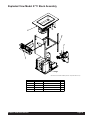
Exploded View Model 5711 (Spinners)
,7(012
Page 28
),/(1$0(&)%$6/''5:6+([SOG9LHZ6SLQQHUV
),/(1$0(&)%$6/''5:6+([SOG9LHZ6SLQQHUV
3$57180%(5 7LWOH
:
:
:
:
:
:
:
:
:
:
:
:
:
:
:
:
:
:
:
:
:
:
:
:
:
:
:
:
:
:
:
:
:
6WRFN$VV\7+'
38//(<:%25(
%HOW9
9DOYH%RG\
%DUUHOO*DVNHW
9DOYH6TXDUH&XW25LQJ
)DV3LQ9DOYH
9DOYH.QRE
9DOYH+DQGOH
3/81*(567'352'6(5,(6
3OXQJHU2
5LQJV
9DOYH6SULQJ
678'9$/9(1(:67</(
)URQW'LVSOD\
)URQW'LVSOD\
)URQW'LVSOD\
(OHF%R[&RYHU
5HPRYDEOH+HDGHUIUDPH
+RSSHU&RYHU6LQJOH
5HDU3DQHO
3DQHO/+6LGH
3DQHO5+6LGH
'DVKHU6FUDSHU
6KDIW6HDO6HW)'$%XQD
6FUDSHU%ODGH1HZ6W\OH
5($567$725%($5,1*
67$725)/$1*(%($5,1*
67$725:(/'0(173,&./('
6SLQQHU'0&
63,11(5%5.7$66(0%/</()7
,QVHUW'ULS7UD\
'ULS3DQ
3DQ'ULS)RUP
4W\
Crathco® 5000 Series Manual
Exploded View Model 5711 Stock Assembly
),/(1$0(:6/''5:6+([SORGHG6WRFN$VV\
,7(012
Crathco® 5000 Series Manual
3$57180%(5
:
%DVH$VV\
7LWOH
4W\
:
)5$0($66(0%/<
:
(9$3$25$725$66<
:
(OHFWULFDO%R[$VVHPEO\
:
5HIULJHUDWLRQ7XEH$VV\
Page 29
Exploded View Model 5711 Stock Assembly (Spinners)
(1$0(:6/''5:6+([SOG6WFN$V\6SLQQU
,7(012
Page 30
3$57180%(5 7LWOH
4W\
:
%DVH$VV\
:
)5$0($66(0%/<7+'
:
:
(9$3$25$725$66<
(OHFWULFDO%R[$VV\7+'
:
5HIULJHUDWLRQ7XEH$VV\
:
%XVKLQJ2'[,'6OHHYH
:
),77,1*(/%2:&8675((7
Crathco® 5000 Series Manual
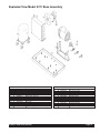
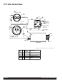
Exploded View Model 5311 Base Assembly
Item Part Number Description
1
2
3
4
5
6
7
8
9
10
11
12
14
W0210169
0W200123
W0200256
W0200411
W0200412
W0200413
W0201079
W0210041
W0320019
W0320209
W0320286
W0321013
W0380009
Motor Cradle
Compressor
Condenser
Fan Mount Bracket
Compressor Spacer
Compressor Grommet
Fan Shroud
Frame Bottom Plate
Drive Motor
Fan Motor
Fan Blade
Motor Adj. Nut
Flange Bearing
Crathco® 5000 Series Manual
Item Part Number Description
15
16
17
18
19
20
21
22
23
24
25
26
30
W0450016
W0610110
W0610264
W0321025
W0611055
W0611074
W0611082
W0611235
W0611246
W0610657
W0611255
W1611005
W0340111
Pulley
#8 X 3/8 Pan Hd..
10-24 X 1/4 Truss Hd.
Motor Stop Bracket
10-24 Hex Nut
1/4-20 Hex Nut
5/16-18 Flange Nut
3/16 Flat Washer
1/4 Lockwasher
5/16-18 X 1/2 Cap
5/16 Split Washer
1/4-20, NC, ESNA
Isolation Bumper
Page 31
Exploded View Model 5511 Base Assembly
Item
1
2
3
4
5
6
7
8
9
10
11
12
13
14
15
18
20
21
23
24
27
28
29
30
31
32
33
Part Number
Description
W0210169
W0200133
W0200256
W0200411
W0200412
W0200413
W0201079
W0210041
W0320020
W0320220
W0320286
W0321013
W0671017
W0380009
W0450016
W0321025
W0611074
W0611082
W0611246
W0610657
W0671018
W0671021
W0671022
W0340111
W0630421
W0610559
W0611248
Motor Cradle
Compressor
Condenser
Fan Mount Bracket
Compressor Spacer
Compressor Grommet
Fan Shroud
Frame Bottom Plate
Drive Motor
Fan Motor
Fan Blade
Motor Adj. Nut
Sound Insulation (Fan)
Flange Bearing
Pulley
Motor Stop Bracket
1/4-20 Hex Nut
5/16-18 Flange Nut
1/4 Lock Washer
5/16-18 x 1/2 Cap
Sound Insulation (Cond)
Sound Insulation (Shro)
Sound Insulation (Motor)
Isolation Bumper
Nylon Cable Clamp
Screw, 1/4-20 x 1 socket Hd. Cap
Lock Washer, 1/4” Split z/p
5511-0107-021-5-15-00
Page 32
Crathco® 5000 Series Manual
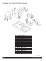
Exploded View Model 5941 Base Assembly
3
4
12
8
7
2
6
6
11
5
10
9
13
1
ITEM
QTY. PART NUMBER
NO.
DESCRIPTION
1
1
W0210044
BASE PAN ASSEMBLY
2
1
W0210169
CRADLE, MOTOR 3312/5311
3
1
W0320019
MOTOR, DRIVE DUAL CYCLE 1/2 HP
4
1
W0321025
Motor Stop Brkt Assy
5
2
W0321013
NUT, MOTOR ADJUSTMENT
6
2
W0380009
BEARING, 1" BORE FLANGE
7
1
W0450016
PULLEY, 0K7 X 1/2" BROWNING
8
1
W0340111
BUMPER, ZB-1214 MINOR RUBBER
8-32 Hex Nut Z/P
9
2
W0611044
10
4
W0610559
11
4
W0611249
Washer, Split, Lock, Z/P
NUT, 5/16-18 FLANGE, LARGE
12
1
W0611082
13
2
61250
Crathco® 5000 Series Manual
Washer, #8 Split Lock
Page 33
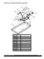
Exploded View Model 5711 Base Assembly
),/(1$0(:6/''5:6+([SORGHG%DVH$VV\
),/(1$0(:6/''5:6+([SORGHG%DVH$VV\
,7(012
Page 34
7LWOH
4W\
:
3$57180%(5
%$6(3/$7($66(0%/<
:
&2035665+39
:
&RQGHQVHU
:
%UNW)DQ0RWRU0QW
:
0RWRU)DQ(63/'(0
:
)DQ%ODGH
:
&5$'/(02725
:
02725'5,9('8$/&<&/(+3
:
:
%($5,1*%25()/$1*(
0RWRU6WRS%UNW$VV\
:
6+528'&21'(16(5
:
%$))/(6+528'
:
18702725$'-8670(17
:
%803(5=%0,12558%%(5
:
38//(<.;%52:1,1*
Crathco® 5000 Series Manual
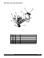
5311 Base Assembly Refrigeration
Item
Part Number Description
1
2
3
4
5
6
7
8
9
10
11
12
13
14
15
16
17
18
19
20
Crathco® 5000 Series Manual
W0650501
W0200314
W0650112
W0200123
W0200256
W0650104
W0201120
W0201331
W0620109
W0201114
W0201113
W0201323
W0620102
W0620110
W0201324
W0201325
W0201326
W1650002
W0620103
W0201039
Access Valve
Capillary Tube, .042 x 12 Ft.
Filter Drier
Compressor
Condenser
Automatic Expansion Valve
Hopper Coolant Lines
Suction Line
3/8" x 3/8" x 1/4" Tee
Evaporator Line
Suction Line
Exp. Valve Solenoid Coolant Line
1/4" x 1/4" x 1/4" Tee
1/4" Copper Elbow
Filter/Condenser Coolant Line
Coolant Line
Solenoid/Cap Tube Line
Solenoid Valves
3/8" Straight Couple
Compressor/Condenser Hot Gas Line
5311-105-021-4-29-00
Page 35
5511 Base Assembly Refrigeration
Item
1
2
3
4
5
6
7
10
11
12
13
14
15
16
17
18
19
20
21
22
23
24
25
26
27
28
29
30
31
Page 36
Part Number Description
W0650501
W0200301
W0650112
W0200133
W0200256
W0650107
W0201120
W0201114
W0201113
W0201323
W0620102
W0620110
W0201324
W0201325
W0201326
W1650002
W0620125
W0201112
W0201371
W0620123
W0201372
W0201373
W0201155
W0650428
W0201220
W0201153
W0201151
W0620112
W0201152
Access Valve
Capillary Tube
Filter Drier
Compressor
Condenser
Automatic Expansion Valve
Hopper Coolant Lines
Evaporator Line
Suction Line
Exp. Valve/Solenoid Liquid Line
1/4" x 1/4" x 1/4" Tee
1/4" Copper Elbow
Filter/Condenser Coolant Line
Condenser To Tee Liquid Line
Solenoid/Cap Tube Liquid Line
Solenoid Valves
1/2" Straight Coupling
Barrel Warmer
Compress./Condenser Hot Gas Line
1/2" 180 Deg. Copper Fitting
Suction Line (Short)
Suction Line (Bent)
Liquid Line
High Pressure Cutout Switch
Liquid Line
1/4 OD x 3/8 ID 90Þ Bell Reducer
3/8" Dia Condenser Connection
3/8" Coupling
5/16 ID x 3/8 ID Straight Coupling
5511-0108-021-3-20-00
Crathco® 5000 Series Manual
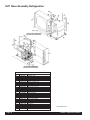
5941 Base Assembly Refrigeration
3
2
1
7
10
8
11
9
ITEM
NO.
1
QTY. PART NUMBER DESCRIPTION
1
2
1
3
1
7
8
9
10
11
1
1
1
1
1
Crathco® 5000 Series Manual
100280
W0620118
male
W0620117
male
W0650125
W0200312
W0200318
W1650002
W1650005
BRACKET, MOUNTING, QD 5931
Quick Disconnect, Male Portion
Quick Disconnect, Male Portion
VALVE, THERM EXP, 3/8 X 1/2 ODF, 30" CAP
DRIER, FILTER SPORLAN #C-033-S
Tube, Capillary .072 OD x .026 ID x 132"
SOLENOID, COMP E5S120S-24/50
SOLENOID, COMP E5S130S-24/50
Page 37
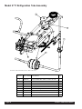
Model 5711 Refrigeration Tube Assembly
),/(1$0(:6/''5:6+5()5,*78%($66<
,7(012 3$57180%(5 '(6&5,37,21
Page 38
4W\
Z
9$/9(7+(50(;3;2')&$3
:
62/(12,'&203(66
:
6ZLWFK3UHVVXUH
:
:
62/(12,'&203(66
&DS7XEH2'[,'[
:
6LJKW*ODVV5HIULJ
:
:
'ULHU)LOWHU
7XEH&DSLOODU\2'[,'[
:
(/%2:&[&
Crathco® 5000 Series Manual
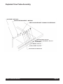
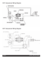
Exploded View Probe Assembly
S.S PROBE - W0572362
ACETAL DELRIN SLEEVE - W0572361
ADD SILICON SEALANT TO BACK OF SLEEVE ONLY
MACHINE SCREW - W0610299
INTERNAL TOOTH LOCKWASHER - W0611224
RING EYE TERMINAL
FLAT WASHER - W0611241
PLASTIC SPACER - W0572360
HOLE IN REAR OF HOPPER PAN
Crathco® 5000 Series Manual
Page 39
Page 40
Crathco® 5000 Series Manual
5000 Series Thick Product Plunger
(W0480463)
5000 Series Standard Product Plunger (W0480462)
CHECK LIST
Slush Cocktail Carb Tube Assy. (W0471075)
(W0631230)
Smooth
Shiny Side
2
Rough Side
of Ceramic
CRATHCO MACHINE ASSEMBLY
1
(CR)
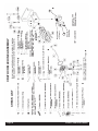
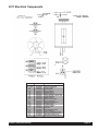
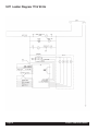
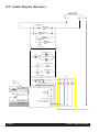
5311 Electrical Components
Item
HS
LBS & RBS
FU
FM
DM
101
100
R1
R2
TR
SW2
SC
RC
CR
SW1
FU2
CB1
FU1
B
LT1
LT1
TB1
66
67
65
Crathco® 5000 Series Manual
Part Number
W1650004
W1650004
WI570616
W0320209
W0320019
W0570712
W0570935
W0570655
W0570655
W0570659
W0570939
W0570603
W0570617
W0570693
W0570934
W0570823
W0650913
W0570842
W0570045
W0570043
W0570044
W0570235
W1570010
W1570011
W1570012
Description
HOPPER SOLENOID
BARREL SOLENOID
FUSE HOLDER
FAN MOTOR
DRIVE MOTOR
POWER CORD
SERVE SWITCH
DRIVE MOTOR CONTACTOR
COMPRESSOR CONTACTOR
TRANSFORMER
MODE SWITCH
START CAPACITOR
RUN CAPACITOR
COMPRESSOR RELAY
ON/OFF SWITCH
3.2 AMP FUSE
CIRCUIT BOARD
5.0 AMP FUSE
BALLAST
FLUORESCENT BULB
LIGHT SOCKET
CIRCUIT TERMINAL BLOCK
YELLOW INDICATOR LIGHT
RED INDICATOR LIGHT
GREEN INDICATOR LIGHT
Page 41
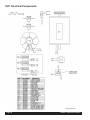
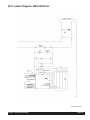
5511 Electrical Components
5511-0102-057-3-20-00
Page 42
Crathco® 5000 Series Manual
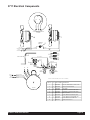
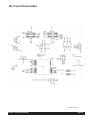
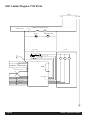
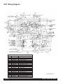
5711 Electrical Components
&
5('
%/$&.
5
<(//2:
6
&2035(6625(/(&75,&$/
+22.83
5('
%/$&.
)$1
)$1/($'6
)$1
)$1/($'6
35(6685(
6:,7&+
36/($'
36/($'
%/8(
)5((=(
*5((1
:+,7( 0,;/2:352%(
67$1'%<
%/$&.
<(//2:%/$&.
25$1*( 0,;287
5('
25$1*(
<(//%/.
<(//2:
+27*$6
62/(12,'
9$/9(
3853/(:+7
<(//2:
ZLUH
QXW
ZLUH
QXW
%/8(02725/($'
5('7$%
%$55(/
62/(12,'
9$/9(
3853/(
/(
53
38 3 , 1 .
5('
*( :
$1
2
25 <(//
%/$&.
+233(5
62/(12,'
9$/9(
%52:102725/($'
5('7$%
),/(1$0(:6/''5:6+(/(&&20321(1
),/(1$0(:6/''5:6+(/(&&20321(176
,7(012 47< 3$57180%(5 '(6&5,37,21
02725
Crathco® 5000 Series Manual
: 7+,6'5$:, 02725'5,9('8$/&<&/(+3
:&200 0RWRU)DQ(63/'(0
:
)DQ%ODGH
:
62/(12,'&203(66
:
62/(12,'&203(66
:
0L[/RZ3UREH
:
/,*+7,1',&$725*519/('
:
/,*+7,1',&$725'.$0%(59
:
/,*+7,1',&$725/75('9
:
6ZLWFK3UHVVXUH
%(5(352'
Page 43
(CR)
(CR)
(CR)
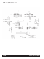
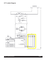
5311 Front Electrical Box
(CR)
Page 44
Crathco® 5000 Series Manual
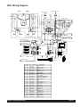
5511 Front Electrical Box
5511-0101-057-3-20-00
Crathco® 5000 Series Manual
Page 45
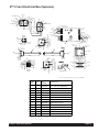
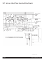
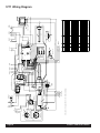
5711 Front Electrical Box
)URQW(OHFWULFDO%R[
<(//%/.
&217$&725
5('
%/$&.
5('
%/$&.
5('
5('
&217$&725
%/$&.
%52:1
%/$&.
5(' %/$&.
5('
%/$&.
%$55(/7+(50,6725
+233(57+(50,6725
%/8(
5('
*5((1
25$1*(
6(59(6:,7&+
<(//2:
3853/(:+7
*5$<:+7
5(':+7
02'(
6:,7&+
*5$<:+7
5(':+7
<(/
*5((1
%/8(
:+,7(
%/$&.
5('
25$1*(
5('
5('
&21752/
%2$5'
%/$&.
3853/(
%/8:+7
3853/(
<(//2:
3853/(:+7
%52:1
%/8(
5('
<(/
<(/
%/8:+7
3853/(
<(/
75$16)250(5
/,*+7
%/8
/,*+7
5('
5('
%/8
*5281'
:+7
5('
%/.
%/.
5('
%/.
$03)86(
%/8:+7
3853/(
%/.
&21752/%2$5'
251*
5('
$03)86(
%/8:+7
3853/(
6(59(6:,7&+
32:(5
6:,7&+
),/(1$0(:6/''5:6+)5217(/(&%2;
Page 46
,7(0
12
47<
3$57
180%(5
'(6&5,37,21
:
62&.(73,1)/825(6&(17
Z
&RQWURO%RDUG
:
7UDQVIRUPHU
:
5HHG6ZLWFK12
:
&RQWDFWRU9&RLO
:
0RGH6ZLWFK
Z
Z
)XVH%ORFN
$PS)XVH
Z
$PS)XVH
Z
2Q2II6ZLWFK
:
%5$&.(76(59(6:,7&+
:
%8/%3,1)/825(6&(17
Crathco® 5000 Series Manual
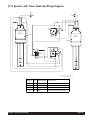
5711 Front Electrical Box (Spinners)
<(//%/.
&217$&725
5('
%/$&.
5('
5('
%/$&.
5('
&217$&725
%/$&.
%52:1
%/$&.
5(' %/$&.
5('
%$55(/7+(50,6725
+233(57+(50,6725
%/8(
%/$&.
5('
%/8
02'(
6:,7&+
*5$<:+7
5(':+7
5('
",5%
5(':+7
:+7
5,*+7
63,11(5 7,0(5
<(/
%/.
<(/
5('
5('
&21752/
%2$5'
%/$&.
3853/(
%/8:+7
3853/(
<(//2:
3853/(:+7
*5((1
%/8(
:+,7(
%/$&.
5('
25$1*(
%52:1
%/8(
%/.:+7
:+,7(
*5$<:+7
6(59(6:,7&+
<(//2:
3853/(:+7
*5((1
25$1*(
5('
%/8:+7
3853/(
<(/
<(/ 75$16)250(5
/,*+7
/,*+7
5('
5('
%/.
%/.
%/.
:+7 %/.
$03)86(
251*
5('
3853/( $03)86(
%/8:+7
3853/(
6(59(6:,7&+
%/.
32:(5
6:,7&+
/()7
63,11(5
7,0(5
%/8:+7 *5281'
:+,7(
&21752/%2$5'
",5%
%/.
%/8(
%/.:+7
5('
:+,7(
5('
5('
5('
%/8
%/8
),/(1$0(:6/''5:6+)517(%2;63,11(56
,7(0
12
47<
Crathco® 5000 Series Manual
3$57
180%(5
'(6&5,37,21
:
%8/%3,1)/825(6&(17
:
62&.(73,1)/825(6&(17
Z
&RQWURO%RDUG
:
7UDQVIRUPHU
:
7LPHU9VHFRQ6KRW
:
5HHG6ZLWFK12
:
&RQWDFWRU9&RLO
:
0RGH6ZLWFK
Z
Z
)XVH%ORFN
$PS)XVH
Z
$PS)XVH
Z
2Q2II6ZLWFK
:
%5$&.(76(59(6:,7&+
Page 47
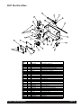
5311 Electrical Box
Item
1
2
3
4
5
6
7
8
9
10
11
Part Number
W0570603
W0570617
W0570655
W0570916
W0570638
W0570934
W0572451
W1570901
W0570423
W0572342
W0650913
Description
Start Capacitor
Run Capacitor
Contactor
Reed Switch
Compressor Relay
On/Off Switch
Electrical Box
Mode Switch
Terminal Strip
Circuit Board Support
Circuit Board
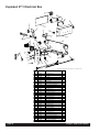
Item
12
13
14
15
16
17
18
19
20
21
22
Part Number
W0570043
W0570044
W0630006
W0630811
W0631629
W1570616
W0570823
W0570842
W0630427
W0572704
W0572705
Description
Light Bulb
Light Socket
Bushings
Capacitor Clips
Electrical Box Lens
Fuse Block
3.2 Amp Fuse
5.0 Amp Fuse
Edgemount Standoff
Serve Switch Bracket
Light Riser
5311-0214-057-11-16-00
5511 Electrical Box
Item
1
2
3
4
5
6
7
8
9
10
11
Part Number
W0570659
W0572705
W0570655
W0570916
W0570618
W0570912
W0572464
W1570901
W1570213
W0572342
W0650913
Page 48
Description
Transformer
Light Riser
Contactor
Reed Switch
Compressor Relay
On/Off Switch
Electrical Box
Mode Switch
Terminal Strip
Circuit Board Support
Circuit Board
Item
12
13
14
15
16
17
18
19
20
21
22
Part Number
W0570043
W0570044
W0630006
W1571078
W0631633
W1570616
W0570823
W0570842
W0630427
W0572704
83106
Description
Light Bulb
Light Socket
Bushings
Relay Bracket
Electrical Box Lens
Fuse Block
3.2 Amp Fuse
5.0 Amp Fuse
Edgemount Standoff
Serve Switch Bracket
Relay
5511-0111-057-11-16-00
Crathco® 5000 Series Manual
5941 Electrical Box
3
5941 ELECTRICAL BOX
18
18
34
4
23
33
30
32
11
13
21
22
15
15
11
1
21
8
19
14
5
31
12
10
35
16
17
35
7
21
2
9
22
19
6
21
20
ITEM
NO.
1
2
3
4
5
6
7
8
9
10
11
12
13
14
15
16
17
18
19
20
21
22
23
30
31
32
33
34
35
Crathco® 5000 Series Manual
QTY. PART NUMBER
1
1
1
1
1
1
1
1
3
1
2
1
1
1
2
1
1
2
2
2
8
2
1
1
1
1
1
1
2
W0572451
W0570655.
W0570043
W0570044
W0572706
W0570934
83231.
w0650913
W0570214
W0600201
83248
W0600202
w0570842
w0570823
w1570616
0076.
83151
86827
w0610015
W0610264
W0610131
W0630006
W0631629
101113
101124
W0570235
W0570045
W0570659
88031
DESCRIPTION
Lighted Elec. Box 5311
Contactor, 24V Coil
BULB,FLUORESENT
SOCKET,LIGHT-LEVITON
Control Board Mount Assembly
Rocker Switch, DPDT
Rocker Switch, 3 Position
Control Board
Terminal Strip, 8 Position
Decal, 3.2 Amp Fuse
6-32 x 1/4 Screw
Decal, 5.0 Amp Fuse
5.0 Amp Fuse
3.2 Amp Fuse
Fuse Block, 1/4"
8-32 x 3/8 Hex Head Ground Screw
Washer, Lock, #8, Ext. Tooth
6-32 Hex Nut
6-32 x 1/4 Screw
SCREW, 10-24 X 1/4 TRUSS HD S.S.
SCRW, 8-32 x 1/4, Self Thrd Ph
Heyco Snap Bushing
Lens, White, Elec. Box
Seal, Electrical Box
Ring Eye, Red, #8
Terminal Block, 4 Circuit
Ballast
Transformer
Heyco Snap Bushing
Page 49
Exploded 5711 Electrical Box
),/(1$0(:6/''5:6+(;3/(/(&75,&$/%2;
),/(1$0(:6/''5:6+
,7(0
12
Page 50
3$57180%(5
'(6&5,37,21
4W\
:
(OHFWULFDO%R[
:
&RQWDFWRU9&RLO
:
7UDQVIRUPHU
:
Z
5HHG6ZLWFK12
$PS)XVH
Z
$PS)XVH
:
7HUPLQDO6WULS3RVLWLRQ
:
62&.(73,1)/825(6&(17
Z
Z
)XVH%ORFN
/+/LJKW%UNW
Z
5+/LJKW%UNW
:
+H\FR6QDS%XVKLQJ
:
(OHFWULFDO%R[/HQV
Z
:
&RQWURO%RDUG
'HFDO$PS)XVH
:
'HFDO$PS)XVH
:
3UREH7KHUPLVWHU
:
0RGH6ZLWFK
Z
:
2Q2II6ZLWFK
&RYHU&DS5HOD\%R[
:
%R[&DS5HOD\
:
5HOD\&RPSUHVVRU
:
+H\FR6QDS%XVKLQJ
:
:
+$51(66&$%/($66<
&DSDFLWRU5XQ
Z
6WDUW&DSDFLWRU
:
%5$&.(76(59(6:,7&+
:
%$//$679+]
7(50),164'*$
5LQJ(\H5HG
:
%8/%3,1)/825(6&(17
Crathco® 5000 Series Manual
Exploded 5711 Electrical Box (Spinners)
),/(1$0(:6/''5:6+(;3/(%2;63,11(56
,7(0
12
'(6&5,37,21
4W\
:
(OHFWULFDO%R[
:
&RQWDFWRU9&RLO
:
7UDQVIRUPHU
:
Z
5HHG6ZLWFK12
$PS)XVH
Z
$PS)XVH
:
7HUPLQDO6WULS3RVLWLRQ
:
62&.(73,1)/825(6&(17
Z
Z
)XVH%ORFN
/+/LJKW%UNW
Z
5+/LJKW%UNW
:
+H\FR6QDS%XVKLQJ
:
(OHFWULFDO%R[/HQV
Z
:
&RQWURO%RDUG
'HFDO$PS)XVH
:
'HFDO$PS)XVH
:
3UREH7KHUPLVWHU
Crathco® 5000 Series Manual
3$57180%(5
:
%8/%3,1)/825(6&(17
:
7LPHU9VHFRQ6KRW
:
0RGH6ZLWFK
Z
:
2Q2II6ZLWFK
&RYHU&DS5HOD\%R[
:
%R[&DS5HOD\
:
5HOD\&RPSUHVVRU
:
+H\FR6QDS%XVKLQJ
:
:
+$51(66&$%/($66<
&DSDFLWRU5XQ
Z
6WDUW&DSDFLWRU
:
%5$&.(76(59(6:,7&+
:
%$//$679+]
7(50),164'*$
5LQJ(\H5HG
Page 51
5711 Side Electrical Box
581
&$3$&,725
%/$&.
5('
%/$&.
%/$&.
%/$&.
%/$&.
%/$&.
&20367$57
5(/$<
5('
<(//2:
67$57
&$3$&,725
%/8
%/.
<(/
:+7
*51
5('
%$//$67
),/(1$0(:6/''5:6+6,'((/(&%2;
,7(0
3$57
47<
12
180%(5
'
Page 52
'(6&5,37,21
: &DSDFLWRU5XQ
Z 6WDUW&DSDFLWRU
%$//$679
:
+]
: 5HOD\&RPSUHVVRU
Crathco® 5000 Series Manual
5311 Spinner Hook-Up with Timer Wiring Diagram
Crathco® 5000 Series Manual
Page 53
5511 Spinner without Timer Hook-Up Wiring Diagram
5511-0100-057-9-14-00
Page 54
Crathco® 5000 Series Manual
5711 Spinner with Timer Hook-Up Wiring Diagram
*5281'
*5281'
12
%/8(
%/$&.:+7
5('
&20
*51'
%/$&.:+7
%/$&.
12
%/8(
5('
%/$&.
*51'
&20
",5%
/()7
63,11(5
5,*+7
63,11(5 7,0(5
5,*+7
63,11(5
",5%
32:(5
6:,7&+
/()7
63,11(5
7,0(5
),/(1$0(:6/''5:
6+63115+22.83:,5(',$
,7(012 47< 3$57180%(5
Crathco® 5000 Series Manual
'(6&5,37,21
:
7LPHU9VHFRQ6KRW
Z
:
2Q2II6ZLWFK
6SLQQHU'0&
6FUHZ[+H[+G*UQ
Page 55
5311 Compressor Wiring Diagram
5511 Compressor Wiring Diagram
5511-0106-057-3-20-00
Page 56
Crathco® 5000 Series Manual
5711 Compressor Wiring Diagram
S
J
J
&
6
&2035(6625(/(&75,&$/
+22.83
5
&217$&725
%/$&.
5('
<(//2:
5('
%/$&.
%/$&.
%/$&.
%/$&.
%/$&.
5('
581
&$3$&,725
%/$&.
<(//2:
&20367$575(/$<
67$57
&$3$&,725
),/(1$0(:6/''5:6+&203:,5,1*',$*5$0
,7(0
12
Crathco® 5000 Series Manual
%/$&.
47< 3$57180%(5
'(6&5,37,21
:
&DSDFLWRU5XQ
Z
6WDUW&DSDFLWRU
:
5HOD\&RPSUHVVRU
:
&RQWDFWRU9&RLO
Page 57
5311 Ladder Diagram 115V 60 Hz
Page 58
Crathco® 5000 Series Manual
5511 Ladder Diagram 208/230V/50 Hz
5511-0103-057-3-20-00
Crathco® 5000 Series Manual
Page 59
5941 Ladder Diagram 115V 60 Hz
115V
L1
ON/OFF SWITCH
R1(1)
L2
G
CURRENT SENSOR ON CB1
DM
BALLAST
FLORECENT LAMP
B
TRANSFORMER
24V AC
12V AC
GND
24V AC
FU2 (3.2 AMP)
FU1 (5.0 AMP)
BARREL THERMISTOR
HOPPER THERMISTOR
SERVE SWITCH
MIX LOW PROBE
1
R1
BS
HS
CB1
2
3
4
5
CURRENT
SENSOR
6
ON/STANDBY/CLEAN SWITCH
7
8
1
2
GREEN-FREEZE
YELLOW-STANDBY
RED-MIX LOW
Page 60
8
VOLTAGE SENSOR
7
3
24V
6
4
12V
5
5
4
6
3
7
2
8
1
Crathco® 5000 Series Manual
5711 Ladder Diagram
9
/
/
5
&855(176(1625
21&%
*
2
'0
'5,9(
02725
5
5
&5
&2035(6625
5(/$<
)0
)$1
02725
35(6685(
6:,7&+
)0
)$1
02725
212))6:,7&+
)/825(6&(17/$03
%$//$67
%
)/825(6&(17/$03
75$16)250(5
9$&
9$&
9$&
*1'
)8$03
)8$03
%$55(/7+(50,6725
+233(57+(50,6725
6(59(6:,7&+
0,;/2:352%(
2167$1'%<&/($16:,7&+
*5((1)5((=(
<(//2:67$1'%<
5('0,;/2:
5
%6
+6
5
&%
&855(17
6(1625
92/7$*(6(1625 9)255(/$<23(5$7,21 932:(56833/< ),/(1$0(:6/''5:6+/$''(5',$*5$0
Crathco® 5000 Series Manual
Page 61
5711 Ladder Diagram (Spinners)
9
/
/
5
&855(176(1625
21&%
*
2
'0
'5,9(
02725
5
5
&5
&2035(6625
5(/$<
)0
)$1
02725
35(6685(
6:,7&+
)0
)$1
02725
212))6:,7&+
)/825(6&(17/$03
%$//$67
)/825(6&(17/$03
%
7,0(5
63,11(502725
5,*+7
7
7,0(5
60
63,11(502725
/()7
7
60
75$16)250(5
9$&
9$&
9$&
*1'
)8$03
)8$03
%$55(/7+(50,6725
+233(57+(50,6725
6(59(6:,7&+
0,;/2:352%(
2167$1'%<&/($16:,7&+
*5((1)5((=(
<(//2:67$1'%<
5('0,;/2:
5
%6
+6
5
&%
&855(17
6(1625
92/7$*(6(1625 9)255(/$<23(5$7,21 932:(56833/< ),/(1$0(:6/''5:6+/$''(5',$63,11(56
Page 62
Crathco® 5000 Series Manual
5311 Wiring Diagram
Item
1
2
3
4
5
6
7
8
9
10
11
12
13
14
15
16
17
18
19
Part Number
Description
W0570603
W0570617
W0570655
W0570423
W0570043
W0570638
W1650004
W0650913
W0570044
W0570823
W1570616
W0570659
W0570045
W0570934
W1570901
W1572132
W0570842
W0570935
W0572704
Start Capacitor
Run Capacitor
Contactor
8 Pin Terminal Strip
Bulb
Compressor Relay
Solenoid Coil
Circuit Board
Light Socket
3.2 Amp Fuse
Fuse Holder
Transformer
Ballast
On/Off Switch
Stand-By Switch
6 Wire Cable Sub Assy.
Fuse 5 Amp
Switch (Serve)
Bracket Serve Switch
5311-0212-057-02-06-01
Crathco® 5000 Series Manual
Page 63
5511 Wiring Diagram
Item
1
2
3
4
6
7
10
11
12
14
15
16
17
18
19
20
21
22
*23
*24
*25
*26
*27
28
Page 64
Part Number
Description
W0570619
W0570617
W0570655
W0570213
W0570618
W0650102
W0570823
W1570616
W0570659
W0570912
W1570901
W1572132
W0570842
W0570916
W0572704
W0570043
W0570044
W0570047
W0572500
W0572501
W0572502
W0572503
W0572504
83106
Start Capacitor
Run Capacitor
Contactor
8 Pin Terminal Strip
Compressor Relay
Solenoid Complete
3.2 Amp Fuse
Fuse Holder
Transformer
On/Off Switch (Toggle)
Mode Switch
6 Wire Cable Sub-As
Fuse 5 Amp
Switch (Serve)
Bracket Serve Switch
Bulb
Light Socket
Ballast
Right Side Harness
Right Elec. Box Harness
Left Elec. Box Harness
Left Side Harness
Electrical Box Wire Bundle
Relay, Pressure Switch
5511-0216-057-10-25-00
Crathco® 5000 Series Manual
5941 Wiring Diagram
RIGHT
SPINNER
LEFT
SPINNER
19
RED
66
9
69
YELLOW/WHT
YELLOW
RED
BLACK
BLK
9
VIOLET/WHT
VIOLET
3
72
1
2
BLUE
BLUE
BLK/WHT
72
GREEN
GREEN
TERMINAL BLOCK
70
70
BLACK
69
72
32
WHT
BLUE
BLUE
72
66
28
BLK/WHT
BLACK
3
RED
5
9
3
8
WHT
68
2
9
BLK
8
68
68
WHT
RED
5
WHT
WHT
68
12
WHT
19
1
26
3
VIOLET
RIGHT
SPINNER
TIMER
18
29
68
22
69
LEFT
SPINNER
TIMER
32
30
YELLOW/WHT
18
31
BLUE
BLACK
RED
BLACK
66
68
2
BLACK
33
8
66
BLK/WHT
WHT
3
67
BLUE
BLUE
70
BLUE
70
67
RED
BLUE
18
67
30
33
16
BLK
5
67
BLUE
BLUE
BLK/WHT
27
22
WHT
WHT
N.O.
BLUE
COM
N.C.
BLK/WHT
70
WIRING DETAIL
69
20
WHT
BLUE
BLACK
69
BARREL SOLENOID
10
HOPPER SOLENOID
7
TO DRIVE MOTOR
WHT
BLACK
23
8
RED
POWER CORD
WHITE
BLACK
24
31
RED
17
12 V.
COM
BLACK
24 V.
7
13
LINE
BARREL
HOPPER
19
15
27
24 V.
12 V.
14
14
8
7
6
5
4
3
2
1
11
18
25
BLUE
2
ORANGE
13
5
12
6
15
VIOLET
5.0
VIOLET
11
VIOLET
10
BLUE/WHT
24
16
3.2
BLUE/WHT
9
TO MIX LOW SENSOR
28
WHT
WHT
1
2
3
4
5
6
7
8
COM
BLACK
14
BLACK
1
2
3
4
5
6
7
8
BLACK
14
WHT
BLACK
21
RED
RED +
ORANGE -
BLUE/WHT
25
17
YELLOW
22
24
4
7
YELLOW
YELLOW
WHITE +
BLACK -
5
1
FRAME GROUND CONNECTION
26
BLACK
12
VIOLET/WHT
21
VIOLET/WHT
GREEN
+
BLUE -GREEN
ORANGE
14
RED/WHT
GRAY/WHT
20
RED/WHT
GRAY/WHT
RED
BLACK
BARREL THERMISTER
BLACK
17
15
13
GREEN
4
VIOLET
BLACK
WHITE
GREEN
RED
25
GREEN
2
6
WHT
GREEN
HOPPER THERMISTER
BLACK
17
WHT
6
10
BLUE/WHT
6
16
4
8
BLACK
20
WHT
TO SERVE SWITCH
BLACK
11
BLACK
BLACK
ITEM QTY
1
1
Crathco® 5000 Series Manual
PART NUMBER
W0570934
DESCRIPTION
ON/OFF SWITCH
2
1
W1570901
STAND-BY SWITCH
3
1
W0570655
CONTACTOR
4
1
W0570045
BALLAST
5
1
W0570235
TERMINAL BLOCK
6
2
W1570616
FUSE HOLDER
7
1
W0570659
TRANSFORMER
8
1
W0570044
LIGHT SOCKET
9
10
1
1
W1650002
SOLENOID COIL(HOPPER)
W1650005
SOLENOID COIL(BARREL)
11
1
W0570935
SWITCH (SERVE)
12
1
W0570043
BULB
13
1
W0650913
CIRCUIT BOARD
14
3
W0570423
8 PIN TERMINAL STRIP
15
1
W0570842
FUSE 5 AMP
16
1
W0570823
3.2 AMP FUSE
17
18
2
W0570504
THERMISTER
2
W0570676
15 SEC. TIMER
19
2
W0470015
SPINNER
20
1
W1570011
FREEZE LIGHT
21
1
W1570010
22
1
W1570012
23
1
W0320019
DRIVE MOTOR
24
1
W0572068
POWER CORD
25
1
W0572362
MIX LOW PROBE
STAND BY LIGHT
MIX LOW LIGHT
Page 65
%/$&.
%/$&.
%/.
%/$&.
*51
<(//2:
%/$&.
)5217)$1
/($'6
*5281'
%/$&.
%$//$67
5($5)$1
/($'6
5('
%/$&.
%/.
%/8
<(/
%/8
32:(5&25'
&203
67$575(/$<
<(/
5('
5('
:+7
%/.
5('
%/8
<(/
&217$&725
32:(5
6:,7&+
5('
<(//2:%/$&.
*5281'
),/(1$0(:6/''5:6+:,5,1*',5$*5$0
67$57
&$3$&,725
%/$&.
*5((1
5('
<(//2:
581
&$3$&,725
5('
5('
%/$&.
%/$&.
%/$&.
:+7
&217$&725
*5((1
72
&2035(6625
*5((1
%/$&.
5('
Page 66
%/$&.
5('
35(6685(
6:,7&+
%/8
%/$&.
5('
/,*+7
5('
<(//2:
*5((1
%/$&.
*$<(//2:62/,'&25(
%/.
0,;/2:
352%(
+233(5
7+(50,6725
25$1*(
*5((1
%/8(
:+,7(
%/$&.
5('
25$1*(
5('
%/$&.
:+,7(
0,;287
67$1'%<
)5((=(
5('
%/$&.
*5$<:+7
Z
Z
Z
Z
:
:
:
:
:
Z
:
Z
:
:
:
:
:
:
:
/,*+7
5('
5('
<(/
%/8:
25$1*(
),/(1$0(:6/''5:6+:,5,1*',5$*5
62&.(73,1)/825(6&(17
%8/%3,1)/825(6&(17
%$//$679+]
%5$&.(76(59(6:,7&+
6ZLWFK3UHVVXUH
2Q2II6ZLWFK
5HOD\&RPSUHVVRU
6WDUW&DSDFLWRU
/,*+7,1',&$725/75('9
&DSDFLWRU5XQ
/,*+7,1',&$725'.$0%(59
/,*+7,1',&$725*519/('
$PS)XVH
)XVH%ORFN
$PS)XVH
&RQWDFWRU9&RLO
5HHG6ZLWFK12
7UDQVIRUPHU
&RQWURO%RDUG
'(6&5,37,21
5('
75$16)250(5
3853/(
$03)86(
3853/(
3$57180%(5
5('
<(//2:
%$55(/
62/(12,'
9$/9(
3853/(:+7
%/8:+7
02'(
6:,7&+
47<
%/$&.
,7(012
3853/(:+7
5(':+7
5('
*5((1
6(59(6:,7&+
25$1*(
%/8(
%52:1
%/8(
&21752/
%2$5'
%/$&.
<(//2:%/$&.
+233(5
62/(12,'
9$/9(
<(//2:
+27*$6
62/(12,'
9$/9(
<(//2:%/$&.
02725
3853/(
%$55(/
7+(50,6725
5711 Wiring Diagram
Crathco® 5000 Series Manual
%/$&.
*5281'
%/.
%/$&.
<(//2:
&203
67$57
5(/$<
%/$&.
5('
%$//$67
5($5)$1
/($'6
),/(1$0(:6/''5:6+:,5,1*',$63,11(56
32:(5&25'
%/$&.
67$57
&$3$&,725
%/$&.
%/$&.
5('
5('
%/$&.
%/$&.
5('
%/.
:+7
72
/()7
63,11(5
32:(5
6:,7&+
5('
5('
<(//
%/8
%/8
<(//
%/.
5('
%/$&.:+7
%/8(
*5((1
<(//
&217$&725
%/$&.
5('
",5%
<(//2:
*5((1
/()7
63,11(5
7,0(5
5('
/,*+7
%/$&.
25$1*(
*5((1
%/8(
:+,7(
%/$&.
5('
25$1*(
%/$&.
5('
:+,7(
%/8(
0,;287
67$1'%<
)5((=(
5('
%/$&.
*5((1
3853/(:+7
5(':+7
*5$<:+7
6(59(6:,7&+
%52:1
%/8(
&21752/
%2$5'
25$1*(
5('
<(//2:
3853/(
/,*+7
5('
<(//
5('
",5%
3$57180%(5
:
:
:
:
:
Z
:
Z
:
:
:
:
Z
Z
Z
:
:
:
:
Z
'(6&5,37,21
62&.(73,1)/825(6&(17
%8/%3,1)/825(6&(17
%$//$679+]
%5$&.(76(59(6:,7&+
6ZLWFK3UHVVXUH
2Q2II6ZLWFK
5HOD\&RPSUHVVRU
6WDUW&DSDFLWRU
/,*+7,1',&$725/75('9
&DSDFLWRU5XQ
/,*+7,1',&$725'.$0%(59
/,*+7,1',&$725*519/('
$PS)XVH
)XVH%ORFN
$PS)XVH
&RQWDFWRU9&RLO
5HHG6ZLWFK12
7LPHU9VHFRQ6KRW
7UDQVIRUPHU
&RQWURO%RDUG
%/8:+7
25$1*(
75$16)250(5
),/(1$0(:6/''5:6+:,5,1*',$63,11(56
5('
<(//
3853/(
$03)86(
47<
5('
%$55(/
62/(12,'
9$/9(
3853/(:+7
5,*+7
63,11(5
7,0(5
%/8:+7
,7(012
02'(
6:,7&+
%/$&.
+233(5
62/(12,'
9$/9(
+27*$6
62/(12,'
9$/9(
<(//2:%/$&.
02725
<(//2:
0,;/2:
352%(
<(//2:%/$&.
+233(5
7+(50,6725
3853/(
%$55(/
7+(50,6725
%/$&.
<(//2:%/$&.
*5281'
%/8
%/8
<(//
&217$&725
%/$&.
5('
5('
581
&$3$&,725
<(//2:
%/$&.
%/$&.
5('
*5((1
%/$&.
5('
72
&2035(6625
*5((1
%/8(
)5217)$1
/($'6
:+7
*51
72
5,*+7
63,11(5
*5281'
$03
)86(
5('
%/$&.:+7
Crathco® 5000 Series Manual
*5((1
35(6685(
6:,7&+
5711 Wiring Diagram (Spinners)
Page 67
%/$&.
Refrigeration Circuit
Page 68
Crathco® 5000 Series Manual
Crathco® 5000 Series Manual
FILTER
DRIER
HIGH
SIDE
3/8
TUBING
3/8
TUBING
BARREL
WARMER
SERVICE
VALVE
LOW
SIDE
S
SOLENOID
VALVE
SERVICE
VALVE
1/2
TUBING
1/4
TUBING
CAPILARY
TUBE
1/4
TUBING
3/8
TUBING
SOLENOID
VALVE
S
3/8
TUBING
HOPPER EVAPORATOR
ACCUMULATOR
EXPANSION
VALVE
BARREL EVAPORATOR
1/2
TUBING
5941 Refrigeration Circuit
Page 69
Grindmaster® Coffee Grinders and Brewers • PrecisionBrew™ Brewing Systems • Espressimo® Espresso Machines
Crathco® Hot Beverage Dispensers • Crathco® Cold and Frozen Beverage Dispensers • AMW Coffee and Tea Systems
Tel (502) 425-4776 • Fax (502) 425-4664 • 1-800-695-4500 (USA & Canada only)
P.O. Box 35020 • Louisville, KY 40232 • USA
www.grindmaster.com • email: [email protected]