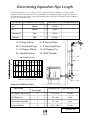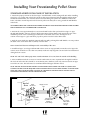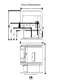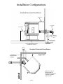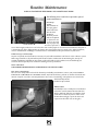
1
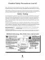
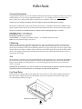
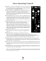
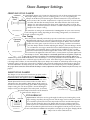
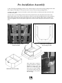
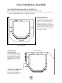
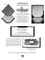
ADVANTAGE PLUS
Pellet Stove
Owners Manual
&
Operating Instructions
THIS STOVE MUST BE PROPERLY INSTALLED AND OPERATED IN ORDER TO PREVENT THE POSSIBILITY OF A
HOUSE FIRE. PLEASE READ THIS ENTIRE OWNER’S MANUAL BEFORE INSTALLING AND USING YOUR WHITFIELD
PELLET STOVE. FAILURE TO FOLLOW THESE INSTRUCTIONS COULD RESULT IN PROPERTY DAMAGE, BODILY
INJURY OR EVEN DEATH. CONTACT YOUR LOCAL BUILDING OR FIRE OFFICIALS TO OBTAIN A PERMIT AND
INFORMATION ON ANY INSTALLATION RESTRICTIONS AND INSPECTION REQUIREMENTS IN YOUR AREA.
– SAVE THESE INSTRUCTIONS –
Congratulations on the purchase of your
Whitfield Advantage Plus Pellet Stove!
When you purchased your Whitfield stove, you joined the ranks of thousands of
concerned individuals whose answer to their home heating system reflects their
concern for aesthetics, efficiency and our environment. We extend our continued
support to help you achieve the maximum benefit and enjoyment available from
your pellet stove.
Please familiarize yourself with this Owner’s Manual before installing your Whitfield
stove. This manual covers, in detail, the necessary steps required in assembling and
installing your Whitfield pellet stove in a safe manner.
We at Pyro Industries, Inc. the manufacturer of the Original Pellet Stove thank you
for selecting a Whitfield as the answer to your home heating needs.
Sincerely,
All of us at Pyro Industries, Inc.
– SAVE THESE INSTRUCTIONS –
Table Of Contents
Safety Precautions
Safety Notice . . . . . . . . . . . . . . . . . . . . . . . . . . . . . . . . . . . . . . . . . . . . . . . . . . . . . 4
Installation Disclaimer . . . . . . . . . . . . . . . . . . . . . . . . . . . . . . . . . . . . . . . . . . . . . 5
Detailed Safety Precautions . . . . . . . . . . . . . . . . . . . . . . . . . . . . . . . . . . . . . . . 4-5
Safety Testing . . . . . . . . . . . . . . . . . . . . . . . . . . . . . . . . . . . . . . . . . . . . . . . . . . . . . . . . . 5
Whitfield Advantage Plus Stove Safety Label . . . . . . . . . . . . . . . . . . . . . . . . . . . 5
Pellets
General Information . . . . . . . . . . . . . . . . . . . . . . . . . . . . . . . . . . . . . . . . . . . . . . . . 6
Clinkering . . . . . . . . . . . . . . . . . . . . . . . . . . . . . . . . . . . . . . . . . . . . . . . . . . . . . . . . 6
Ash . . . . . . . . . . . . . . . . . . . . . . . . . . . . . . . . . . . . . . . . . . . . . . . . . . . . . . . . . . . . . . 6
Fuel Feed Rates . . . . . . . . . . . . . . . . . . . . . . . . . . . . . . . . . . . . . . . . . . . . . . . . . . . 6
Stove Operating Controls . . . . . . . . . . . . . . . . . . . . . . . . . . . . . . . . . . . . . . . . . . . . . 7
Stove Damper Setting . . . . . . . . . . . . . . . . . . . . . . . . . . . . . . . . . . . . . . . . . . . . . . . . . 8
Operating Instructions
Pre-Lighting Instructions . . . . . . . . . . . . . . . . . . . . . . . . . . . . . . . . . . . . . . . . . . . . 9
Starting Your Whitfield Pellet Stove . . . . . . . . . . . . . . . . . . . . . . . . . . . . . . . . . . . 9
Turning Off Your Whitfield Stove . . . . . . . . . . . . . . . . . . . . . . . . . . . . . . . . . . . . 9
General Operating Considerations
Proper Burn Characteristics . . . . . . . . . . . . . . . . . . . . . . . . . . . . . . . . . . . . . . . . . 10
Pellet Feed/Pellet Size . . . . . . . . . . . . . . . . . . . . . . . . . . . . . . . . . . . . . . . . . . . . . . 10
Long Burn Time . . . . . . . . . . . . . . . . . . . . . . . . . . . . . . . . . . . . . . . . . . . . . . . . . . .10
Automatic Safety Features . . . . . . . . . . . . . . . . . . . . . . . . . . . . . . . . . . . . . . . . . . 10
Power Outage . . . . . . . . . . . . . . . . . . . . . . . . . . . . . . . . . . . . . . . . . . . . . . . . . . . .10
Overheating . . . . . . . . . . . . . . . . . . . . . . . . . . . . . . . . . . . . . . . . . . . . . . . . . . . . . . 10
Safe Shut Down of Your Stove . . . . . . . . . . . . . . . . . . . . . . . . . . . . . . . . . . . . . . 10
Thermostat Installation . . . . . . . . . . . . . . . . . . . . . . . . . . . . . . . . . . . . . . . . . . . . . . . . 11
Routine Cleaning
Burn Grate . . . . . . . . . . . . . . . . . . . . . . . . . . . . . . . . . . . . . . . . . . . . . . . . . . . . . . . 12
Ash Pan . . . . . . . . . . . . . . . . . . . . . . . . . . . . . . . . . . . . . . . . . . . . . . . . . . . . . . . . . . 12
Ash Slide Plates . . . . . . . . . . . . . . . . . . . . . . . . . . . . . . . . . . . . . . . . . . . . . . . . . . . 12
Heat Exchanger Tubes . . . . . . . . . . . . . . . . . . . . . . . . . . . . . . . . . . . . . . . . . . . . . . 12
Table Of Contents (Cont’d)
Stove Installation
Stove Installation Check List . . . . . . . . . . . . . . . . . . . . . . . . . . . . . . . . . . . . . . . . .13
Pre-Installation Assembly . . . . . . . . . . . . . . . . . . . . . . . . . . . . . . . . . . . . . . . . . . . 14
Stove Installation Configurations
Floor Protection . . . . . . . . . . . . . . . . . . . . . . . . . . . . . . . . . . . . . . . . . . . . . . . . . . . 15
Clearances to Combustibles . . . . . . . . . . . . . . . . . . . . . . . . . . . . . . . . . . . . . . . . .15
Stove Vent Pipe/Intake Installation
General Guidelines For Installing Exhaust System . . . . . . . . . . . . . . . . . . . . . . 16
Determining Equivalent Pipe Length . . . . . . . . . . . . . . . . . . . . . . . . . . . . . . . . . .17
Installing Your Freestanding Pellet Stove
Standard Horizontal Exhaust Installation . . . . . . . . . . . . . . . . . . . . . . . . . . . . . . .18
Stove Dimensions . . . . . . . . . . . . . . . . . . . . . . . . . . . . . . . . . . . . . . . . . . . . . . . . . 19
Installation Configurations
Standard Horizontal Installation . . . . . . . . . . . . . . . . . . . . . . . . . . . . . . . . . . . . . 20
Horizontal Vent Configurations . . . . . . . . . . . . . . . . . . . . . . . . . . . . . . . . . . . . . 20
Interior Vertical Vent Through Ceiling & Roof . . . . . . . . . . . . . . . . . . . . . . . . . 21
Interior Vent Installation Into Existing Class A (metal) Chimney . . . . . . . . . . 21
Exterior Vertical Vent Straight Out & Up Through Roof . . . . . . . . . . . . . . . . . . 21
Vertical Vented Into A Masonry Flue . . . . . . . . . . . . . . . . . . . . . . . . . . . . . . . . 21
Mobile Home Installation Configuration . . . . . . . . . . . . . . . . . . . . . . . . . . . . . . 22
Installing Your Insert Pellet Stove
Venting Into An Existing Chimney . . . . . . . . . . . . . . . . . . . . . . . . . . . . . . . . . . . . 23
Built In Heater Installation . . . . . . . . . . . . . . . . . . . . . . . . . . . . . . . . . . . . . . . . . . 24
Routine Maintenance
Door Rope Gasket . . . . . . . . . . . . . . . . . . . . . . . . . . . . . . . . . . . . . . . . . . . . . . . . . 25
Exhaust Vent . . . . . . . . . . . . . . . . . . . . . . . . . . . . . . . . . . . . . . . . . . . . . . . . . . . . . . 25
Motor Lubrication . . . . . . . . . . . . . . . . . . . . . . . . . . . . . . . . . . . . . . . . . . . . . . . . . 25
Cleaning of Internal Exhaust Passages . . . . . . . . . . . . . . . . . . . . . . . . . . . . . . . . 25
Window Wash . . . . . . . . . . . . . . . . . . . . . . . . . . . . . . . . . . . . . . . . . . . . . . . . . . . . 25
Appendices
Appendix A - Advantage Plus Trouble-Shooting Guide . . . . . . . . . . . . . . . . 26-28
Appendix B - Optional Accessories . . . . . . . . . . . . . . . . . . . . . . . . . . . . . . . . . . 29
Appendix C - Shroud . . . . . . . . . . . . . . . . . . . . . . . . . . . . . . . . . . . . . . . . . . . . . . 30
Appendix D - Warranty . . . . . . . . . . . . . . . . . . . . . . . . . . . . . . . . . . . . . . . . . . . . 31
Appendix E - Replacement Parts Lists and Views . . . . . . . . . . . . . . . . . . . . 32-35
The drawings in this manual are not drawn to architectural scale and should be used for reference only.
Actual dimensions as printed in the text are accurate. Refer to this manual for detailed installation
dimensions, instructions, specifications and other requirements.
Safety Precautions
Safety Notice
THIS STOVE MUST BE PROPERLY INSTALLED AND OPERATED IN ORDER TO PREVENT THE POSSIBILITY OF
A HOUSE FIRE. PLEASE READ THIS ENTIRE OWNER’S MANUAL BEFORE INSTALLING AND USING YOUR
WHITFIELD PELLET STOVE. FAILURE TO FOLLOW THESE INSTRUCTIONS COULD RESULT IN PROPERTY
DAMAGE, BODILY INJURY OR EVEN DEATH. CONTACT YOUR LOCAL BUILDING OR FIRE OFFICIALS TO
OBTAIN A PERMIT AND INFORMATION ON ANY INSTALLATION RESTRICTIONS AND INSPECTION
REQUIREMENTS IN YOUR AREA.
Installation Disclaimer
THIS STOVES EXHAUST SYSTEM WORKS WITH NEGATIVE COMBUSTION CHAMBER PRESSURE AND A
SLIGHTLY POSITIVE CHIMNEY PRESSURE. THEREFORE, IT IS IMPERATIVE THAT THE EXHAUST SYSTEM BE
GAS TIGHT AND INSTALLED CORRECTLY. SINCE PYRO INDUSTRIES, INC., HAS NO CONTROL OVER THE
INSTALLATION OF YOUR STOVE, PYRO INDUSTRIES GRANTS NO WARRANTY, IMPLIED OR
STATED FOR THE INSTALLATION OR MAINTENANCE OF YOUR STOVE, AND ASSUMES NO
RESPONSIBILITY FOR ANY CONSEQUENTIAL DAMAGE(S).
Detailed Safety Precautions
Fuel - With its advanced UltraGrate technology, the Whitfield Advantage Plus is designed and approved for
the burning of wood residue pellets with up to 3% ash content (i.e...cardboard, nut hulls, cherry pits etc.).
The burning of agricultural residues (i.e.... corn, alfalfa etc.) in pellet form is not permitted. Failure to comply with this restriction will void all warranties and the safety listing of the stove. Consult with your dealer
for more information on approved pellet fuels and the proper burn grate for the fuels in your area.
Cleaning - There may be some build-up of dust and smaller quantities of soot or creosote in the exhaust
system over the burn season. This will vary due to the ash content of the fuel being burned. A precautionary inspection on a regular basis is advisable to determine the necessity of cleaning.
Continuous Operation - When operated correctly, the Whitfield Advantage Plus cannot be over-fired.
Continuous operation at a maximum burn can, however, shorten the life of the electrical components
(blowers, motors, and electronic controls), and is not recommended. Typical approved operation would
include running at setting numbers Two, Three or Four, with occasional running on number Five during
the coldest periods of the winter. The blower speed control should be turned to #5 when operating the
stove on the number five heat setting.
Liquid Flammables - Gasoline or other flammable liquids must NEVER be used to start or “freshen-up” the
fire. Keep all such liquids well away from the stove at all times.
Ashes - Any ashes removed from the Whitfield Advantage Plus must be deposited in a metal container
with a tight-fitting lid. The closed container of ashes should be placed on a noncombustible floor or on
the ground, well away from all combustible materials, pending final disposal. If the ashes are disposed of
by burial in soil or otherwise locally dispersed, they should be retained in the closed container until all cinders have been thoroughly cooled.
Power - The appliance is provided with a detachable, grounded electrical cord. This cord should be
plugged into a standard, 115 volt, 60 Hz grounded electrical outlet. The approximate power requirement
is 200 watts, or will peak to approximately 700 watts for 15 minutes when the self-igniter is operating. The
power supply cord must be routed to avoid contact with any of the hot or sharp exterior surface areas of
the stove. In addition, any Whitfield Advantage Plus stove that is installed in a mobile home must be:
Connected to a source of outside air, Electrically grounded to the steel chassis and Bolted to the floor in
compliance with and according to H.U.D. requirements unless otherwise specified by state or local authorities.
Soot Formation - For all wood pellet fuel-burning heater products the combustion gases will contain small
particles of fly ash. The fly ash will collect in the exhaust venting system and restrict the flow of the flue
gases, over time. Incomplete combustion, such as occurs during startup, shutdown, or incorrect operation
of the room heater will lead to some soot formation which will collect in the exhaust venting system. The
exhaust venting system should be inspected at least once every year to determine if cleaning is necessary.
Detailed Safety Precautions (cont'd)
Auger - Pellet fuel is fed to the burn grate by a screw auger. This auger is driven by a high torque motor.
The auger is capable of doing serious harm to fingers. Keep pellets in the hopper at all times and keep
fingers away from auger. The auger can start and stop automatically at any time while the stove is running.
Smoke Detector - Depending on your local codes, a smoke detector may be required in the room where
the stove is installed. We recommend that smoke detectors be installed in all homes and maintained in an
operational condition at all times, no matter whether you are using a heating appliance or not.
Safety Testing
In accordance with the specifications and procedures listed in UL 1482 & ASTM E1509 for solid fuel room
heater, the Whitfield Advantage Plus pellet stove has been independently tested and listed by Warnock
Hersey, (an accredited testing laboratory) to UL, ULC and CSA standards. UL 1482 states requirements for
installations as a freestanding room heater, or hearth insert for masonry or metal (zero clearance) fireplaces. The safety listing label is located on an inside hopper surface of the Advantage Plus stove. Please
read this safety label carefully. It contains important information about installation and operation of your
Whitfield Pellet Stove.
This Owner’s Manual is provided to you to supplement, rather than replace or update, the information
contained on the safety label. Note that your STOVE’S serial number is located on the safety label. Your
stoves serial number is preceded by a “WH-”. The serial number for insert stoves is also located on a label
under the hopper lid. This appliance is designed specifically for use only with pelletized fuels. It is tested
and listed for residential installation according to current national and local building codes as:
●A
●
Freestanding Room Heater
A Mobile Home Heater
●
●
A hearth insert when installed into a masonry or factory built fireplace.
A built-in heater
Note:This stove is not intended for use in commercial installations other than where the stove is being sold without prior
approval from Pyro Industries,Inc.
The stove will not operate using natural draft,nor without a power source for the blower and fuel feeding systems. The appliance
is provided with an exhaust connector for a 3 inch listed type “L” double wall pellet vent pipe with stainless steel inner liner.
Whitfield Advantage Plus Pellet Stove Safety Label
Whitfield pellet stoves and fireplace inserts are safety tested and listed by Warnock Hersey Professional
Pellet Fuels
General Information
Using the UltraGrate burn system, the Whitfield Advantage Plus has been designed to burn wood residue
pellets with up to 3% ash content. Agricultural pellets (i.e… Corn, alfalfa etc.) are not permitted to be
burned in the stove. Dirty fuel will adversely affect the performance of the stove.
Caution: The use of unapproved, dirty, wet and/or high salt content fuel will void the warranty!
Wood pellets manufactured to the Pellet Fuels Institute (P.F.I.) Certification Standard are available in two
grades, Standard and Premium. The primary difference between the two is the ash content of the pellets.
TheP.F.I., specification for Standard Grade & Premium Grade residential pellet fuel is as follows:
CHLORIDES (Salt): Less than 300 p.p.m..
BULK DENSITY: 40 lb. / cu. ft. minimum
MOISTURE CONTENT: 8% maximum
ASH CONTENT: < 3% maximum (Standard Grade) < 1% maximum (Premium Grade)
FINES: 0.5% maximum through a 1/8”screen
Clinkering
Silica (or sand) in the fuel, along with other impurities, can cause clinkering. A clinker is a hard mass of
silica formed in the burning process. Clinkering is a function of the fuel, (not the stove), but adversely
affects the performance of the stove by blocking off the air passages in the grate. Even P.F.I. approved pellet fuel may tend to clinker. A clinker can be removed from the burn grate and placed in the ash pan with
the use of the grate scraper/ash pan tool furnished with your stove. See Routine Maintenance for more
information on cleaning.
Ash
The frequency of removal of the ash and maintenance performed on the stove is directly proportional to
the ash content of the fuel and the operation duration of your Whitfield Stove. Low ash fuel may allow
longer intervals between cleaning, however, a stove burning high ash fuel may need to be cleaned as
often as everyday.
PLEASE NOTE: Pyro Industries, Inc., has no control over the manufacturing of pellet fuel and will not be held
responsible for poor stove performance or any damage caused by inferior pellet fuels.
Fuel Feed Rates
Different brands of pellets will feed at varying rates due to their size and density (length and diameter).
This may require a slight adjustment in the damper control or the pellet feed control to compensate.
See Operating Instructions on page 9.
UltraGrate Configuration
Stove Operating Controls
● Start Switch — The push-button START switch activates the convection blower
and the combustion blower. If the exhaust does not reach operating temperature within 30 minutes, the stove will automatically shut down. The blowers
can be restarted by pushing the START switch again.
● Auger On/Off Switch — The AUGER ON/OFF switch activates the fuel feed
(auger) motor only. The START switch has to be activated to give power to the
AUGER ON/OFF SWITCH. When the AUGER ON/OFF SWITCH switch is
turned off, the fuel feed will stop and the blowers will continue to operate
until the stove has cooled down sufficiently (up to 45 minutes); then the stove
blowers will automatically turn off.
● Heat Output Switch — When on manual operation, the HEAT OUTPUT switch
provides the ability to burn at five burn rates. Pressing the heat output switch
will increase the setting by one position. (After setting #5 it will revert to #1).
The HEAT OUTPUT switch alters the fuel feed rate and the combustion air
supply simultaneously. The control is preset to provide the optimum ratio of
fuel and air at each setting.
● Thermostat Operation —While on thermostat operation, the stove operates
under two settings. There is a “pilot”(low) setting and a “demand”
(high) setting. If your thermostat senses the room heat to be higher
than your selected temperature, the thermostat will set the stove to the
“pilot”or low setting. This is equivalent to physically setting the stove on
HEAT OUTPUT setting #1. If your room temperature is lower than the select
ed thermostat temperature, the thermostat will operate the stove at the HEAT
OUTPUT switch setting you have manually selected. Use a HEAT OUTPUT
switch setting from #2 through #5. The heat output light will flash on and off
during thermostat operation.
● Auger “On”Light — The red light on the control panel indicates that there is
power to the auger motor. Under normal operation, this light will blink
on and off.
● Blower Speed Switch — This button on the control panel controls the
Control Board
speed of the convection fan. Turning up the fan will increase the amount of
heat into the room. For the best efficiency use the maximum blower speed when high heat output
settings are used. The control will limit the blower settings to 2 & 3 at heat output settings 4 & 5 respectively.
In other words,when heat output is set to 5, the blower will scroll through speeds 3, 4 and 5.
● Combustion Fan Trim — The Combustion Fan Trim is located just above the Heat Output Selector switch.
Turning the Trim Control counterclockwise will decrease the amount of combustion air entering the burn
grate. Turning the control clockwise will increase the amount of combustion air entering the burn grate. The
Trim Control is factory set at the (0) position.
● Auger Trim Control — The Auger Trim Control is located just above the AUGER ON/OFFf switch. Turning the
Trim Control counterclockwise will decrease the amount of fuel delivered to the burn grate. Turning the con
trol clockwise will increase the amount of fuel delivered to the burn grate. The trim control is factory set at
the (0) position.
● Convection Fan Trim — The convection fan trim is located on the backside of the control panel. This can be
used to eliminate fan noise by trimming fan speed slightly above or below a noise band. It can also increase
air circulation velocity on #5 setting if required.
NOTE: It is recommended that the damper be used to fine tune your stove to your particular fuel & installa
tion, (see page 8). It is also recommeded that you contact your Whitfield Dealer before adjusting the combus
tion, convection or auger trim controls.
Stove Damper Settings
FREESTAND STOVE DAMPER
The “push-pull” damper rod is located on the lower left side of the Freestand model stove.
The proper damper setting, to use as a starting point, is 2”. It is set by pulling the
damper out all the way and measuring the distance between the side panel and the
2”
inside surface of the set collar. If adjustment is required, loosen the set screw on the
set collar, with the allen wrench provided. The collar will now slide freely on the
damper rod. After adjustments have been made, tighten the collar set screw. The
damper rod must now be pushed in until the set collar contacts the side panel. This
completes the damper setting.
Starting
Point
(Shown Pulled-out)
As stated the 2” setting is the recommended “starting point” for your stove. You may
need to change this setting depending on the venting configuration, site elevation or
the brand of pellets being used.
Fine Tuning
This is the process that will provide the proper air-to-fuel ratio. If your flame is
red/orange with evidence of soot at the top of the flame, you need more air. Pull the
damper out until the flame becomes yellow and begins to “dance”. If the air blows
pellets out of the grate or puts the fire out on low settings, you have too much air.
Push the damper farther in. When adjusting the damper, short 1/4”changes should
be used. Run the stove appx. 30 minutes before additional damper adjustments are
made. When your particular damper setting has been established, the set collar
should be loosened and positioned against the surface of the side panel. The collar
(Damper Pushed In)
set screw must be tightened at this time. This is a safety feature to protect against accidental damper closure. If the damper is accidentally pushed in too far, pellets can pile-up
in the grate. In extreme cases pellets can accumulate back up in the feed tube. Pellets can
smolder and produce smoke in the house. Once the damper is set for your particular fuel and installation, it will not
need to be readjusted unless a different type of pellet fuel is used. If the flame begins to look lazy, with a
red/orange colored flame, do not immediately adjust your damper. First check for ash build up either in the grate,
below the grate or in the vent system. These conditions can restrict the combustion air flow and upset the air-tofuel ratio. Remember to always shut your stove down and allow it to cool completely prior to cleaning. NOTE: If
the proper flame cannot be achieved with the damper control, adjustment of the trim controls may be necessary. (see
page 7)
Operating
Position
INSERT STOVE DAMPER
The damper rod, on the Insert model stove projects out the
face of the shroud on the lower left side. All of the damper
information above also applies to the Insert stove. The 2”starting
point set dimension is measured between the surface of the
bottom plate and the inside surface of the set collar. These
adjustments are done with the black damper knob removed
and the side shroud panel swung open. When completing the
damper setting, the side shroud panel is closed allowing the
damper rod to pass through the slot in the panel, (as shown).
The plastic damper knob can now be threaded
back onto the damper rod.
2”
Starting Point
(Shown Pulled-out)
STOVE BREAK-IN
MORE AIR
LESS AIR
OUT
IN
Face of Shroud
On an Insert
Important Note: All stoves need to go through a break-in period. During this period,
(appx. 4-8 bags of pellets), the auger motor and the auger feed screw need to break
in to reach the specified fuel feed rate. Expect the fuel feeds and the flame appearance to be low during this time. The damper will need to be readjusted after the
break-in period. It is recommended that the stove be monitored during this period.
Due to the fact that the pellet feed increases through the break-in period, the fuel-toair ratio could become imbalanced and pellets could pile up in the grate. Simply pull the
damper out for more combustion air.
Operating Instructions
Lighting Stove With Fastfire™ Self-Igniter:
1. Fill the hopper with recommended pellet fuel and plug stove into wall outlet.
2. Push the Start button on the control board to activate the igniter.
3. Press the Auger ON/OFF Switch to the “ON” position.
4. Pellets will start feeding into the grate and should begin to ignite within three to seven minutes. The selfigniter will automatically shut-off after 15 minutes.
5. If the auger system is not primed with pellets, as in a first time start-up or when the stove has completely
run out of fuel, it may take a few extra minutes to start. In these circumstances if the stove does not start after
the 15 minute ignition c ycle, unplug stove, plug back in and press start button.
6. Air is drawn from the convection air system and is blown across the igniter element to produce a flow of
super heated air. This stream of air is directed through a hole in the back of the burn grate.
Tip: set the blower speed (convection air) selector to a higher setting for better start-up.
7. After the pellets are burning well, press the HEAT OUTPUT selector to the desired setting. Combustion air
and the pellet fuel feed rate will adjust automatically as the HEAT OUTPUT selector switch is pressed. The
flame should be bright yellow in color and there should be no evidence of soot formation at the top of the
flame. Press the Blower Speed switch to increase or decrease the desired amount of convection air from your
stove. If operating your stove with a wall thermostat, adjust the heat output selector switch to the desired
demand mode (#2 through #5 on the heat output selector switch).
Manual Lighting Procedure:
If it is ever necessary to light your stove manually the following procedure should be followed.
If Priming Is Required
1. Fill the hopper with recommended pellet fuel and plug the stove into the wall outlet.
2. Press the Start switch on the control panel. This will activate both blowers. Press the Auger ON/OFF
switch on the control panel. This will activate the auger motor. Next, press the heat output switch to position
#5 (maximum feed rate).
3. Look through the combustion chamber door and when you see the first pellets dropping into the grate the
auger is then fully primed. It will take 10 to 15 minutes to prime the auger.
4. Once the auger is primed, unplug the stove to turn off the blowers and auger for a minimum of 30 seconds.
You need only do this when priming the auger. Once the stove is shut down, plug it into the wall outlet again.
Manual Starting Steps
1. Place a recommended fire starter (see your dealer for appropriate fire starter) in the burn grate and put a
handful of pellets on top of the starter. DO NOT USE FLAMMABLE LIQUIDS TO START YOUR STOVE.
2. Light the fire starter in the grate with a match and close the door.
3. After approximately 10 seconds, press the START SWITCH. You will notice that the fire will become
active and there will be air coming from the heat exchanger tubes.
4. After the pellets in the grate are burning sufficiently (red hot coals), press the Auger ON/OFF switch:
this will activate the auger motor, and pellets will begin to feed into the burn grate. Your blower motors
will continue to operate.
5. After the pellets are burning well, press the HEAT OUTPUT selector to the desired setting. Combustion
air and the pellet fuel feed rate will adjust automatically as the HEAT OUTPUT selector is pressed. The
flame should be bright yellow in color and there should be no evidence of soot formation at the top of
the flame. Press the Blower Speed switch to increase or decrease the desired amount of convection air
from your stove.
If operating your stove with a wall thermostat, adjust the heat output selector switch to the desired
demand mode (#2 through #5 on the heat output selector switch).
Turning Off Your Whitfield Pellet Stove:
Press the Auger ON/OFF Switch to turn the fuel feed of f. Pellets will stop feeding and the red light will stop
blinking. Both blowers will continue to operate. The blowers will automatically turn off after 30 to 45 minutes.
The low temperature switch will also shut the stove down safely if it runs out of fuel.
General Operating Considerations
Proper Burn Characteristics:
The flame in your stove should be bright yellow under normal operation. If the flame becomes lazy with a
reddish/orange color, the damper position may need to be changed to provide more combustion air.
Excessive amounts of flyash built-up in the grate, clinkers in the grate, or leakage of air (if the grate is not
properly seated) will starve the fire for air. (See ROUTINE MAINTENANCE for information on cleaning the
stove). If the problem persists, review the troubleshooting section at the end of this manual.
Pellet Feed/Pellet Size:
The pellet feed system is designed to handle a wide range of pellet sizes up to a maximum of 5/16" diameter.
Different pellets may feed at considerably different rates. You may notice a dif ference in the burn if you
change pellet fuel sizes. The longer the pellet, the slower it will feed and vice versa. If the stove will not
stay burning at the minimum fuel feed setting, those particular pellets may not be feeding fast enough. If
this happens, reduce the amount of combustion air by adjusting the collar on the damper rod. The factory
setting is 2”.
Long Burn Time:
The stove may be safely operated on a continuous basis, but it is recommended that it be turned down
overnight or when the room is vacated for long periods of time. A 40 lb. bag of pellets should last
approximately 9 hours on high and over 24 hours on low, depending on the type and size of pellets you are
burning. Burn times will vary plus or minus 2 hours depending on the type of pellets burned.
Note: It is normal for some ash to build up on the inner glass surface at the lower burn settings.
AUTOMATIC SAFETY FEATURES
Power Outage:
During a power outage, the stove will shut down safely. It will not automatically restart when the power is
restored unless the exhaust temperature is still hot enough. The solid state control has an internal memory that will retain heat output and blower speed settings through voltage interruptions. A small amount of
smoke may leak from the top of the window glass, the hopper and from the combustion air intake, if the
stove is vented horizontally. This will not persist for more than 3 to 5 minutes and will not be safety hazard.
It may set off your smoke alarm. To re-light the stove, follow the normal procedure for starting your stove.
Note: If the area in which you live is prone to frequent power outage, it is recommended that a minimum of 8
ft. (2.5 m) of vertical vent pipe be included in a freestanding installation to induce a natural draft in the event
of a power failure.
Overheating:
A high temperature switch will automatically shut down the stove if it overheats. The stove will need to be
manually re-lit. Allow up to 45 minutes cooling time before re-lighting. Keep enough convection air going
through stove to keep it cooling properl y, this will ensure long life of stove. If the overheating continues,
contact your dealer for more information.
Safe Shut Down of Your Stove:
Push the Auger ON/OFF Switch to the “OFF” position. This will turn the auger motor off and pellets will
stop feeding. Both blowers will continue to operate for a period of time (up to 45 minutes) until the
exhaust temperature cools sufficiently. The blowers will automatically turn off at that point.
Thermostat Installation
NOTE: ALWAYS DISCONNECT POWER BEFORE PERFORMING THE
THERMOSTAT INSTALLATION.
Jumper Wire
To Install A Wall Thermostat:
1. Check the type of thermostat you are about to install, Solid State Electrical thermostats are NOT
approved for use with the Advantage Series pellet stoves. Consult your authorized Whitfield Dealer for
more details.
2. Unplug your stove from the wall outlet.
3. Locate the thermostat connection block on the back of the stove.
4. Remove the jumper wire from the “jacks”on the connection block.
5. Insert the two wires from your thermostat into the jacks (one per jack).
6. Plug in the stove and you are ready to operate with your thermostat!
NOTE: If the jumper wire is missing, and you do not have a thermostat installed, your stove will operate
on Heat Output position # 1 all the time and at all settings.
Routine Cleaning
NOTE: STOVE WILL NEED TO BE SHUT OFF AND COOLED ENOUGH
TO HANDLE BEFORE ROUTINE CLEANING IS PERFORMED.
ALWAYS DISCONNECT POWER BEFORE DOING ANY ROUTINE CLEANING.
The following areas need to be inspected during Routine Cleaning:
● Burn Grate
● Ash Slide Plates (Free Standing Model Only)
● Ash Pan
● Heat Exchanger Tubes
Burn Grate: The burn grate should be inspected periodically to assure that the air holes have not become clogged
with ash or clinkers. The burn grate can easily be cleaned
with the grate scraper/ash pan tool, or it can be removed
for cleaning. It is very important to monitor the ash build
up under the burn grate, as excessive amounts of ash will
block combustion air from entering the grate, causing pellets to pile-up in the grate. The ash build-up under the
grate is easily dumped into the ash pan by pulling out the
center ash slide weekly as shown in the photo below.
Freestand & Insert Model Burn Grate
Freestand Ash Pan: The
ash pan will have to be
emptied periodically,
depending on amount of
fuel consumed. The ash
pan is located in the
pedestal. It can be
removed by turning the
T-Bar latch fully counterclockwise. Then pull ash
pan away from stove. Ash Ash Slide Plates Freestand Only
Slide Plates: Ash that accumulates around the grate can be
“dropped”into the ash pan without opening the firebox
door. Simply pull open the ash release slide plates as
shown in photo above using the grate scraper tool provided. Remove the ash pan as shown to the left.
Note: Make sure to fully close the plates when finished. Failure
to close the ash release slide plates completely
may cause the fuel to burn poorly (due to
reduced air flow through the grate), which may
then cause pellets to “pile up”in the grate.
Insert Ash Pan: The Insert Model stove has
two ash pans, an upper and lower. They
should be emptied whenever necessary. The upper ash pan is
accessed by opening the door and simply sliding the ash pan out.
The lower ash pan is attached to the lower trim panel. Lift out this
entire assembly for ash removal.
Be sure to dump ashes into a noncombustible container. All ash
removal and cleaning should be
done while stove is cold.
Freestand Ash Pan
Insert Upper & Lower Ash Pans
Heat Exchanger Tubes: A rod located above the combustion chamber door
is used for cleaning the tubes. By pulling this rod in and out a few times,
you will clean the fly ash off the heat exchanger tubes. If your stove was
recently turned off, the rod may still be hot.
Handy Hint: You may want to wrap a damp cloth around the rod when you clean the tubes.
This will prevent fly ash from being drawn into your house from the pulling action of the rod.
Freestand & Insert Model
Heat Exchanger Tubes
Stove Installation
Stove Installation Checklist
Check off each item as you go through your installation. As part of the installation process:
It is strongly recommended that you have an Authorized Whitfield Dealer install your stove. If you install
the stove yourself, you should review your installation plan with the Authorized Whitfield Dealer.
❑ Read the ENTIRE Stove Installation section first.
❑ Read the Insert or Freestand section (whichever applies).
❑ Determine the appropriate measurements and locations for your installation.
❑ Follow the general installation directions under Stove Installation & the Installation section
appropriate to your stove.
❑ Be sure to pre-fit all items before you install, fasten, or set up the stove permanently.
Prior to lighting your stove:
❑ Review the Safety Precautions section.
❑ Review the Pellets Section.
❑ Review the Operating Instructions.
❑ Follow the Operating Instructions.
After you have begun operation of your stove:
❑
❑
Review the Routine Cleaning / Maintenance information.
Enjoy the warmth from your new Whitfield Advantage Plus Pellet Stove!
Pre-Installation Assembly
1. After removing the packaging from the stove, lift the hopper lid, and remove all pre-packaged items that
were shipped in the hopper. Also open the stove door and remove all pre-packaged items.
2. Using a 7/16”socket or open end wrench, remove the two bolts from the bottom that secure the stove
to the wooden pallet.
3. If your stove is a freestanding model, remove the pedestal from its box and place it beside the stove.
With a helper, lift the stove onto its pedestal base. Put the six 1/4” bolts through the holes in the mounting
flange of the pedestal and into the six threaded inserts in the stove bottom. Two of these are where the
stove was originally secured to the pallet. Tighten all six fasteners with a properly sized wrench or socket
(3/8”).
1
6
2
5
3
Remove The Two Bolts From
Under The Pallet
Pedestal/Ash Pan Assembly
4
Attach Stove To Pedestal
By Inserting Six Bolts
After stove body is secured to
pedestal install the sidepanel
attachment screws. Find 2 #8
screws in a small bag in the
accessory kit. Using a Phillips
screw driver install screw from
underneath the side panel at
the front edge.
Stove Installation Assembly
Your Whitfield Advantage May Be Installed As:
● A freestanding unit with a pedestal placed on a noncombustible floor pad.
● A mobile home heater placed on a non-combustible floor pad, with a source of outside air, bolted
down and electrically grounded to the chassis of the home.
Floor Protection
6”
6”
Your Whitfield pellet stove must be
installed on a non-combustible pro tective floor pad of minimum 3/8”
thickness material or a masonr y
hearth. The hearth or floor pad must
extend a minimum of 6”in front of
and from each side of the stove or to
the nearest permitted combustible
material if less than 6”.
Hearth Pad
Floor/Hearth Pad
Clearances to
Combustibles
Combustible Wall
1”
The following minimum clearances to combustible materials
must be maintained. Keep all
combustibles at least 18”(horizontally) away from the glass
windows.
1”
6”
(ALCOVE CLEARANCES)
Maximum Alcove depth: 24”.
Minimum Alcove height: 47-1/2”
Minimum Alcove Width: 37”
1”
Stove Vent Pipe/Intake Installation
IT IS RECOMMENDED THAT ONLY AN AUTHORIZED DEALER INSTALL
YOUR PELLET STOVE. THE FOLLOWING INSTALLATION GUIDELINES
MUST BE FOLLOWED TO ENSURE CONFORMITY WITH BOTH THE SAFETY
LISTING OF THE STOVE AND LOCAL BUILDING CODES.
General guidelines for installing the exhaust system:
A 3 or 4 inch listed type “L” pellet vent exhaust system must be used for freestanding installations and
attached (and sealed) to the pipe connector provided on the back of the stove. Use a 3-to-4 inch adapter
or a 3-to-4 inch Tee in order to run 4 inch pipe.
The vent termination must be located no less than 48” (1.2m) from any opening through which flue gases
could re-enter the building, (i.e. windows and doors) not less than 24”(.6m) from an adjacent building,
and not less than 7’(2.2m) above grade when located near public walkways. The final termination of the
exhaust system must be configured so that flue gases do not jeopardize the safety of people passing by,
overheat combustible portions of nearby structures or enter the building. Keep brush, plants and shrubs
at least 36”(.9m) away from vent termination. Since sparks may escape from the exhaust pipe of any stove,
always use caution when positioning the vent pipe. (Refer to pipe manufacturer's instructions when
installing and terminating the exhaust.)
Ninety-degree elbows accumulate fly ash and soot which reduces the exhaust flow and performance of
the stove. Horizontal runs of pipe will collect fly ash as well. It is recommended that a single or double
clean-out ‘tee’ be installed at every 90 degree turn so that fly ash can accumulate at the bottom of the 'tee'.
If a 90 degree turn connects a vertical run of pipe to a horizontal run (as you follow the exhaust away from
the stove), a tee is not required. At any other 90 degree turn, installation of a clean-out tee is recommended to permit periodic cleaning of both the horizontal and vertical runs of pipe.
Total length of horizontal vent must not exceed 25ft. (7.7m). See page 17.
CAUTION: On all direct vent installations (short, horizontal runs); care should be taken when choosing
a location for terminating the vent. (It is NOT recommended to directly vent the exhaust on the prevailing
wind side of the house).
“DO NOT INSTALL A FLUE DAMPER IN THE EXHAUST VENTING SYSTEM OF THIS UNIT”.
“DO NOT CONNECT THIS TO A CHIMNEY FLUE SERVING ANOTHER APPLIANCE”.
FIREPLACE INSERT:
● A 3” single-wall, stainless steel flexible or rigid exhaust pipe may be used for insert installations and must
be attached to the stove with a single or double wall, stainless ‘tee’ with a clean-out cap. The stainless
steel ‘tee’ can be inclined at 45 degrees to enable the vent to be centered on the stove, and allows the
‘tee’ to be cleaned out more easily without removing the stove.
● When venting into an existing chimney (masonry or factory built) the chimney must be cleaned, with all
creosote, dust and ashes removed.
● The “L” vent or single wall stainless exhaust system must be installed so as to be GAS TIGHT! The vent
manufacturer’s installation procedures must be followed. In addition, pipe connections, joints and all
pipe seams within the home should be sealed with room temperature vulcanizing, high temperature
silicone sealer ( RT V ) .
If an insert is to be installed into an unlined masonry chimney, it is recommended that the 3” or 4” rigid or
flex pipe be extended to the top of the existing chimney. The top of the existing chimney should be sealed
with a metal plate after the pellet vent has been installed.
Determining Equivalent Pipe Length
To determine whether a 3”or 4” exhaust system is required for your installation, review the sample
installation below. Fill out the top chart, and calculate your total equivalent pipe length. After you have
the total equivalent pipe length, use the chart at the bottom of the page to determine if your installation
requires 3”or 4” exhaust pipe.
Type of Pipe # of Elbows or Feet of pipe
Equivalent Feet Total Equivalent Feet
o
Elbows
x
5(1.5m)
o
Elbows
x
3(1m)
Horizontal
Pipe
x
1(.3m)
Vertical
Pipe
x
5(1.5m)
90
45
B
A- 90 Deg. Elbow
E- 8’ Vertical Pipe
B- 1’ Horizontal Pipe
F- 2’ Horizontal Pipe
C- 45 Degree Elbow
G- 90 Degree Tee
D- Standoff Braces
H- Wall Thimble
A
C
D
Pipe Selection Chart
30
E
4 INCH DIAMETER ONLY
20
F
10
3 OR 4 INCH DIAMETER
G
0
1
2
3
4
5
6
7
8
9
10
Altitude in Thousands of Feet
H
Sample Installation Chart
Type of Pipe
# of Elbows or
Feet of pipe
Equivalent Feet Total Equivalent Feet
o
2
x
5 ft. (1.5m)
10 (3m)
45 Elbows (C)
o
1
x
3 ft. (1m)
3 (1m)
Horizontal Pipe(B&F)
3
x
1 ft. (.3m)
3 (1m)
Vertical Pipe(E)
8
x
.5 ft. (.15m)
4 (1.2m)
90 Elbows/Tee(A &G)
TOTAL: 20
Installing Your Freestanding Pellet Stove
STANDARD HORIZONTAL EXHAUST INSTALLATION
1. Locate the proper position for the listed type “L” wall thimble. Avoid cutting wall studs when installing
your pipe. Use a saber saw or key hole saw to cut the proper diameter hole through the wall to accommodate the wall thimble. Use extreme caution to avoid cutting into power lines within the wall of the
home. The hole size will depend on the brand of pellet vent that you are using. Install the wall thimble
in the hole.
ALL INTERLOCKING PIPE CONNECTIONS WITHIN THE ROOM MUST BE SEALED WITH RTV AND SECURED
WITH A MINIMUM OF 3 FASTENERS PER CONNECTION.
2. Position the stove approximately 12”(.3m) from the wall on the floor pad. Push listed type “L” pipe
through wall thimble. Squeeze a bead of high temperature silicone (RTV) sealer around the end of the
machined portion of the 3”(76mm) pipe connector on the back of the stove. Firmly push on a
section of listed type “L” pipe until inner pipe liner pushes into the bead of RTV sealer.
3. Push the stove (with pipe attached) towards wall. Pipe will go through the wall thimble. Do not position
the back of the stove closer than 1”(25mm) from the wall.
Note: Greater back clearance will improve the serviceability of the stove.
4. Install listed type “L” 45 degree elbow with rodent screen or cap (optional) on outside end of pipe. The
rodent screen should be no less than 1/2”(13mm) mesh and may clog with soot and ash if left unattended
during the burn season.
NOTE: The end of the exhaust pipe must extend a minimum of 12”(.3m) from the outside of the building.
5. If the installation includes a source of outside combustion air; cut a separate hole through the wall for
the fresh air tube. This tube should be 1-5/8”(42mm) [min.] diameter, steel only. Connect outside air pipe
to air inlet on stove. This tube must be terminated with a 90 degree elbow or hood.
NOTE: AIR MAY ALSO BE DRAWN FROM A VENTED CRAWL SPACE UNDER THE HOME. ALL JOINTS FOR
CONNECTOR PIPE SHALL BE REQUIRED TO BE FASTENED WITH AT LEAST THREE SCREWS. IF VENTED HORIZONTALLY, JOINTS SHALL BE MADE GASTIGHT IN A MANNER AS SPECIFIED ABOVE. INSTALL VENT AT
CLEARANCES SPECIFIED BY THE VENT MANUFACTURER.
Back of
Stove
Quick
Disconnect
Straight “L-vent”
Pipe
Wall
Thimble
45˚
Elbow
Exhaust
Port
Inlet-Air
Port
Metal Fresh
Air Pipe
Lytherm
Gasket
Holes through
the Wall for the
Thimble &
Fresh Air Pipe
45o Degree
Elbow Joint
for Fresh
Air Pipe
Stove Dimensions
25”
5-3/8”
12-1/2”
25”
Dimensions Plus or Minus 1/4”
Installation Configurations
Standard Horizontal Installations
1”Minimum
45o Degree
Elbow
6”Minimum
12”
Minimum
from outer
wall
12”Minimum
from ground
or other
surfaces
NON-COMBUSTIBLE Hearth Pad
(3/8”Minimum Thickness)
Standard Horizontal Installations
3” Minimum
Between Wall
and Pipe
1”
Right Wall
1”
NOTE: If you vent to
the Right Wall, the
vent pipe must maintain a
3” clearance parallel
to the left wall.
Installation Configurations (Cont’d)
Venting Options
The Advantage Plus may be connected to an existing flue or by installing listed type “L” vent pipe. If a
liner is run all the way to the top of the existing chimney, the existing flue should be sealed with a steel
plate. Start a vertical run with a Tee at the back of the stove. Other options are illustrated below.
Rain Cap
24”
Minimum
Length
Keep attic
Insulation away
from Pipe
Existing
chimney
pipe
Flashing
Pipe
increaser
Interior
Vertical Vent thru
Ceiling & Roof.
Interior Vertical
Vent into Existing
Class A Chimney.
3”
Min.
Optional
Complete
Liner
Clean Out
Tee
Exterior
Vertical Vent
3”
Min.
Extend pipe to
the top if
existing chimney
is corroded
or damaged
Vertical Vent into
a Masonry Flue
Optional
Clean out
Door
Mobile Home Installation
IN ADDITION TO THE STANDARD INSTALLATION INSTRUCTIONS, THE FOLLOWING INSTRUCTIONS MAY BE
REQUIRED BY LOCAL, STATE OR FEDERAL BUILDING CODES:
● Stove must be permanently bolted to the floor.
● Stove must have a permanent outside air source.
● Stove must be permanently electrically grounded to the steel chassis of the home. The location selected
for ground attachment to the stove must be dedicated for this purpose.
● Refer to page 17 for list of commonly used vent components.
● NOTE: THE GROUNDING OF THIS PRODUCT, AT INSTALLATION, MUST COMPLY WITH NFPA-70
STANDARDS, CSA C22.1 IN CANADA,AS WELL AS ANY LOCAL CODES.
WARNING:
CAUTION:
DO NOT INSTALL IN A SPACE USED AS A BEDROOM.
THE STRUCTURAL INTEGRITY OF THE MANUFACTURED HOME FLOOR, WALL
AND CEILING/ROOF MUST BE MAINTAINED.
Bolt
Floor
Non-combustible
Floor Pad
Chassis
MOBILE HOME EXHAUST VENT PIPE INSTALLATION GUIDELINES
Use only listed type “L” pellet vent pipe. Pipe should extend at least 3 feet above the part of the roof
through which it passes. The top of the pipe should be at least 2 feet above the highest required elevation of any part of the mobile home within 10 feet of the pipe.
If exhaust vent exits the mobile home at a location other than the roof, and exits at a point 7 feet or
less above the ground level on which the mobile home is position a guard or method of enclosing
the pipe shall be provided at the point of exit for a height of up to 7 feet. The openings, if any, in this
guard shall not allow a 3/4”rod to pass through. A 1/2”rod could pass through but should not be
able to touch the pipe when inserted through the opening a distance of 4 inches.
Installing Your Insert Pellet Stove
VENTING INTO AN EXISTING CHIMNEY
The Advantage Insert may be installed in
a masonry or factory built fireplace as
shown to the right. When installing into a
masonry chimney, it is recommended
that the exhaust vent be extended to the
top of the chimney as shown to the lower
right. However, if the vent pipe does not
extend to the top of the chimney, the
pipe must extend a minimum of 18”
above the damper. You must seal the
damper area with a steel plate.
IMPORTANT NOTE!!
MAKE SURE THE CHIMNEY
AND FIREBOX ARE CLEAN AND
FREE OF SOOT AND ASHES
BEFORE INSTALLATION BEGINS.
FAILURE TO DO SO MAY
RESULT IN THE TRANSFER OF
SOOT INTO THE ROOM BY
WAY OF THE CONVECTION
“Direct Vent”
A Direct Vent May Be
Made Through The
Chimney Structure If
Local Codes Permit.
Seal Chimney
Top With Steel
Plate And Or
Pipe Support
Rain
Cap
The Vent Pipe Must Extend A Minimum
Of 18”Above The Damper. The
Chimney Must Not Be Corroded Or
Damaged In Any Way For This Type Of
Installation To Be Permitted.
Metal
Plate To
Provide
Seal
Optional
Access Door
Clean
Out
Tee
“Direct Connection”
(Not Allowed In Canada)
Optional
Metal
Plate
18”
Min.
Clearance
6”
Min.
“Full Chimney Reline”
Recommended for ALL
Chimney installations
Clean
Out
Tee
Built In Heater Installation
Stove Dimensions for the Advantage Plus Insert that will be Enclosed within the frame work
are HEIGHT (20 1/4”) WIDTH (24”) DEPTH (13 1/2” + OR – 1/4”).
Wood Frame
Shroud
The Advantage Insert may be framed
directly into a wall. Below are two (2)
examples of this. The exhaust installation
requirements are the same as for a
Freestanding stove. Refer to “Installing
your Freestanding Stove” for information
about installing and proper hook-up of
the exhaust.
1”
#1) This example
Minimum
Air Gap
shows the exhaust
directly venting to the
Wall
Thimble
outside horizontally to
Type “L”
the rear of the stove.
45 Degree
Vent Pipe
6”
Min.
Elbow OR
End Cap
12”Min.
DO NOT BLOCK
VENT OPENING
NOTE: For Built-In Installations You Must
Order Enclosure Kit #11950055.
#2) This example shows the
exhaust vented vertical off a
cleanout Tee. This shows a
Chase to enclose the pipe.
** The Framing opening for this installation
needs to be:
HEIGHT= 24”
WIDTH = 34”
DEPTH = 14”
Type “L”
Vent Pipe
3”
Minimum
Air Gap
Wood Frame
Pipe
Stand-off
Bracket
Fire
Stop
** The Framing opening for
this installation needs to be:
HEIGHT= 22 1/2”
WIDTH = 39 3/4”
DEPTH = 24”
Shroud
6”
Min.
DO NOT BLOCK
VENT OPENING
Clean
Out
Tee
Routine Maintenance
UNPLUG STOVE BEFORE PERFORMING ANY MAINTENANCE WORK
The following areas need to be inspected as part of
routine maintenance:
Door Rope
Gasket:
The condition of
the rope gasket
around the door
and windows
should be
checked periodically and replaced
or repaired if necessary. A one inch
strip of paper may
Door Gasket
be used to perform a
test of the integrity of the door seal. Close the door on the paper in several different locations and pull. It
is normal to feel only a slight amount of friction. The door gasket does not need to be “tight”in all areas,
since a small amount of leakage is not hazardous or detrimental to the performance of your stove.
Exhaust Passages and Vent Pipe:
Inspect frequently and clean when necessary. Fly ash will accumulate at all bends in the exhaust system.
Note: Large amounts of fly ash build-up will create a lack of combustion air. Removing the Tee cap on
vertical installations will allow an inspection of the ash build-up in the exhaust Tee and will help you
to decide how frequently more extensive cleaning must be performed.
Motor Lubrication:
THE BLOWERS ARE PERMANENTLY LUBRICATED BY THE MANUFACTURER.
Rear Stove Compartment:
The rear stove compartment should be cleaned periodically (a minimum of once a year.) DISCONNECT
ELECTRICAL CORD PRIOR TO CLEANING STOVE. Any household dust, pet hair or sawdust should be vacuumed or wiped out of the rear compartment of the stove, Freestanding or Fireplace Insert model. The
electrical components
should be wiped clean.
Window Wash:
Periodically insert a small piece of cardboard
(a business card) between the window trim
and the window. Slide the card back & forth
a few times to clear any dust or fibers from
the window wash gap. Open the door and
repeat from the other side of the glass.
Window Wash
APPENDIX A
TROUBLE-SHOOTING
Unplug Stove Before Performing any Maintenance work
PROBLEM
Fire burns with a lazy
orange flame. Pellets build
up in the grate and the window gets sooted up.
CAUSE(S)
There is insufficient combustion air.
SOLUTIONS
Remove any clinkers or ash from
the bottom of the grate that might
be obstructing the primary air
holes.
Change to a better grade of fuel if
necessary.
Check that the damper has been
opened enough for the amount of
fuel feed.
Check that the heat exchange
tubes are not coated with ash.
Clean internal exhaust ducts.
Check gasket seal around the door.
Use a thin strip of paper, 1 in. wide.
Open the door and close it on the
paper strip. A slight friction should
be felt when the paper strip is
pulled. Repeat this process at various locations around the door gasket. Replace the door gasket if
necessary
Check for blockage in the air inlet
tube or exhaust pipe. Clean as necessary.
Close ash slide plates.
Have your Whitfield dealer check
your combustion blower.
Fire goes out or stove shuts
down automatically
The hopper is empty
Refill hopper.
Pellets are not feeding.
See (Pellets will not feed)
next page.
The high limit temperature
switch has tripped.
Allow stove to cool for 1 hour and
re-light. If the stove has been
APPENDIX A
TROUBLE-SHOOTING (CONT’D…)
Unplug Stove Before Performing any Maintenance work
PROBLEM
CAUSE(S)
SOLUTIONS
operating at a medium to high burn
rate and the convection fan has
been turned down low then the fan
should be turned up higher. If this
problem persists (particularly at
lower burn rates) then the high
limit snap switch should be
replaced by your certified Whitfield
dealer.
Pellets will not feed.
Stove runs for 30 minutes
then shuts down.
Blowers will not shut off
after the Auger has been
switched off and the stove
has cooled down.
There is too much combustion air for the amount of
fuel.
Adjust the damper to reduce combustion air flow.
The hopper is empty.
Refill hopper.
The auger motor or circuit
board may be defective. The
pressure switch tap or hose
may be blocked.
Check to be sure that there is no
blockage in the pressure tap or
hose. Have your certified Whitfield
dealer diagnose the problem and
clean or replace any necessar y
parts.
Back pressure in venting tripping pressure switch.
If new installation check for excessive 90˚ bends, long horizontal runs
or excessive vertical run of 3”pipe.
Possibly change to 4”pipe. If older
installation check for excessive ash
accumulation in pipe or other
obstructions. Clean out pipe.
The exhaust gases are not up
to temperature.
Press start switch and re-light stove
if necessary.
The low limit snap switch is
not operating correctly.
Have your certified Whitfield dealer
replace the low limit snap switch.
The wires to the low limit
snap switch are loose or
disconnected.
Check wires between the snap
switch and the wiring harness.
Make sure that there are good connections between the wires and
their terminals.
The low limit snap switch has
failed in the closed position.
Have your certified Whitfield dealer
replace the low limit snap switch.
APPENDIX A
TROUBLE-SHOOTING (CONT’D…)
Unplug Stove Before Performing any Maintenance work
PROBLEM
Blowers will not operate
when the start switch is
depressed.
CAUSE(S)
SOLUTIONS
There is no power to the
stove.
Check that the stove is plugged in
to the wall outlet.
There is no power to the control board.
Check to see if your circuit breaker
has tripped.
Check the wire connections on the
high limit snap switch and Control
board.
There is soot or fly ash in
the house.
The window is being cleaned
when the stove is operating.
Turn down the convection fan or
turn off stove before cleaning to
prevent dispersion of ash and soot
into the room.
There is leakage at the joints
between the combustion fan,
connection or exhaust pipe
connections. This will be evi denced by dust on the
impeller of the convection fan,
and in the heat exchanger
area.
Seal up any leaks in the exhaust
system with room temperature
vulcanizing silicone sealer (RTV).
The vacuum cleaner is leaking.
DO NOT use a standard household
vacuum or “shop vac” as the filters
will leak the fine particles of ash.
Clean the stove with an approved
Ash Vacuum ONLY.
APPENDIX B
Solid
Solid
OPTIONAL ACCESSORIES
Hearth Pads
Trimmed in solid oak, Whitfield
hearth Pads are available in an
array of colors and color
combinations to complement and
enhance any decor.
Each is made from tough tile and
non-staining epoxy grout, so
they’re as durable and easy to
clean as they are beautiful.
Two Tone
Two Tone
Colors for Both Styles
SOLID PADS
Mission ● Eggshell
Sterling ● Jade ● Dusk
●
●
TWO TONE PADS
Mission/Carmel ● Eggshell/Sky Blue
Sterling/Jade ● Eggshell/Mission ● Sterling/Dusk
●
An insert hearth support is available to provide support for the front of the insert. It
should be used when the fireplace’s hearth
extension is lower than the floor of the existing firebox that the insert fits into. The hearth
support attaches to the bottom front of the
insert stove, and and adds by adjustment, 3 1/2
to 9 inches of support height to the front of
the unit.
Decorative Log Sets
Add the touch of real wood to
your pellet stove.
Contact your local Authorized Whitfield Dealer for more information.
APPENDIX C
SHROUD PANEL ACCESS
48.00”(Lrg)
44.00”(Med)
40.75”(Sml)
36.00”
(Lrg)
22”
Shrouds and
magnetic shroud
trim are available in
three sizes for your
Advantage Insert:
Small:
28.5”(72.4 cm) high by
40.3/4”(103.5 cm) wide
Medium:
32”(81.3 cm) high by
44”(111.75 cm) wide
Large:
36”(91.4 cm) high by
48”(121.9 cm) wide
32.00”
(Med)
28.50”
(Sml)
APPENDIX D
WARRANTY
THIS WARRANTY IS ISSUED BY PYRO INDUSTRIES, INC. (MANUFACTURER)
AND EXTENDS ONLY TO THE ORIGINAL PURCHASER OF THIS PRODUCT.
The Manufacturer provides a five year limited warranty on all steel parts (except the grate), and a 2 year
limited warranty on all electrical components. These warranties extend from the date of the original purchase. There is expressly no warranty on the following components: glass window, Fiberglass rope gaskets, firebrick, grate, paint, exterior brass or enamel finish. This warranty covers defects in materials and
workmanship in covered components, provided the product has been installed and operated strictly in
accordance with Manufacturer's printed instructions. This warranty does not cover damage or breakage
caused by improper handling, misuse or unauthorized modification. Without limiting the foregoing, the
use of fuels other than pelletized wood will void all warranties and liabilities. All claims under this warranty must be made in writing to the Manufacturer at Pyro Industries, Inc., 695 Pease Road, Burlington WA.
98233 and should include the following:
1. Name, address, and telephone number of servicing dealer.
2. Name, address, and telephone number of purchaser.
3. Date of purchase.
4. Model & Serial number of stove.
5. Nature of the defect, malfunction and/or complaint. Local representatives are to inspect parts and or
stoves. If the inspection indicates that the failure was due to defective material or workmanship in covered components and that the other terms and conditions of this warranty have been complied with,
the Manufacturer's sole duty and liability under this warranty shall be limited to the Manufacturer's
replacement or repair, at Manufacturer's option, of the defective stove or part. The purchaser shall
assume all costs of shipping to and from the Manufacturer and shall be responsible for all losses dur
ing shipment if the stove is not defective. If a stove is found to be defective by the Manufacturer, ship
ping costs will be reimbursed. Removal and reinstallation costs are not covered under this warranty.
NEITHER THE MANUFACTURER, NOR THE SUPPLIER TO THE PURCHASER, ACCEPTS RESPONSIBILITY, LEGAL OR OTHERWISE,
FOR INCIDENTAL OR CONSEQUENTIAL DAMAGE TO PROPERTY OR PERSONS RESULTING FROM THE USE OF THIS PROD UCT. ANY WARRANTY IMPLIED BY LAW, INCLUDING BUT NOT LIMITED TO IMPLIED WARRANTIES OF MERCHANTABILITY
OR FITNESS, SHALL BE LIMITED TO ONE YEAR FROM THE DATE OF ORIGINAL PURCHASE. WHETHER A CLAIM IS MADE
AGAINST THE MANUFACTURER BASED ON A BREACH OF THIS WARRANTY OR ANY OTHER TYPE OF WARRANTY, EXPRESSED
OR IMPLIED BY LAW, MANUFACTURER SHALL IN NO EVENT BE LIABLE FOR ANY SPECIAL, INDIRECT, CONSEQUENTIAL OR
OTHER DAMAGES OF ANY NATURE WHATSOEVER IN EXCESS OF THE ORIGINAL PURCHASE PRICE OF THIS PRODUCT. ALL
WARRANTIES BY MANUFACTURER ARE SET FORTH HEREIN AND NO CLAIM SHALL BE MADE AGAINST MANUFACTURER ON
ANY ORAL WARRANTY OR REPRESENTATION.
Some states or countries may not allow the exclusion or limitation of consequential damages, or limitations of implied warranties, so the limitations or exclusions set forth in this warranty may not apply to you.
This warranty gives you specific legal rights and you may also have other rights which vary from different states or countries.
APPENDIX E
REPLACEMENT PARTS
Common To Both Freestand & Insert
Freestand Only
1
#17150009 Scraper Rod
31 #11850447 Side Panel-LHS, (slate)
2
#11750400 Door Assembly (slate)
32 #11850147 Side Panel-LHS, (black)
3
#11750100 Door Assembly (black)
33 #11850347 Side Panel-LHS, (brown)
4
#11750300 Door Assembly (brown)
34 #11850547 Side Panel-LHS, (green)
5
#11750500 Door Assembly (green)
35 #11850448 Side Panel-RHS, (slate)
6
#11750123 Hinge Pins, gold (Set of 2)
36 #11850148 Side Panel-RHS, (black)
7
#11750015 Firebrick set
37 #11850348 Side Panel-RHS, (brown)
8
#11750003 Door Handle, gold
38 #11850548 Side Panel-RHS, (green)
#12055912 Control Board (NOT SHOWN)
39 #11850446 Top Panel (slate)
#61057208 Glass Gasket (4’)
40 #11850146 Top Panel (black)
9
10 #11750021 Hinge Bracket
41 #11850346 Top Panel (brown)
11 #11756300 Auger
42 #11850546 Top Panel (green)
12 #11750011 Brick Clips (2 clips)
43 #12050093 Quick Disconnect 3” Vent Side
13 #17150246 Ultragrate Replacement
44 #61050016 3” Quick Disconnect Gasket
14 #12050011 Combustion Blower
45 #11854151 Bottom Trim (slate)
15 #12146109 Convection Blower
46 #11851151 Bottom Trim (black)
16 #12153900 Auger, Flange
47 #11853151 Bottom Trim (brown)
17 #12046300 Auger Motor
48 #11855151 Bottom Trim (green)
#12058811 Wiring Harness (NOT SHOWN)
49 #11850149 Rear Panel (black only)
18 #12145903 Pressure Switch
50 #11850158 Brass Trim Set
19 #12146402 Replacement Glass
51 #11855400 Pedestal W/Ashpan (slate)
20 #12058820 Molded end, Power Cord
52 #11855100 Pedestal W/Ashpan (black)
21 #12057601 Ceramic Snapswitch
53 #11855300 Pedestal W/Ashpan (brown)
22 #12147705 Snapswitch, 250 DG, 60T21
54 #11855500 Pedestal W/Ashpan (green)
23 #61050003 Auger End Plate Gasket
56 #11751305 Damper Rod Freestand
24 #61057100 1/2” Door Rope (7 ft.)
25 #61057203 Common Convection fan Gasket
26 #61050005 Comb. Fan Gasket
27 #11720198 Manual
28 #11720099 Video
29 #12041300 Auger Collar & Screw set (3 pieces)
30 #12050111 Combustion Fan (Motor Only) Kit
55 #12140213 Igniter Replacement
Common to Freestand & Insert Stove Parts
Freestand Stove Parts
APPENDIX E
REPLACEMENT PARTS
Insert Only
Lid Supt. Kit (NOT SHOWN)
79 #11955451
Hearth Support Kit (Green)
57 #11950156
Accent Trim Kit
80 #11950126
Damper Rod (Insert)
58 #72050005
Hole Plug Kit
59 #11951166
Top Panel (black)
60 #11953166
Top Panel (brown)
61 #11954166
Top Panel (slate)
62 #11955166
Top Panel (green)
63 #11951168
RHS Panel, (black)
64 #11953168
RHS Panel, (brown)
65 #11954168
RHS Panel, (slate)
66 #11955168
RHS Panel, (green)
67 #11951167
LHS Panel, (black)
68 #11953167
LHS Panel, (brown)
69 #11954167
LHS Panel, (slate)
70 #11955167
LHS Panel, (green)
71 #11950052
Upper Ash Pan
72 #11951163
Lower Ash Pan Black (w/t trim)
73 #11953163
Lower Ash Pan Brown (w/t trim)
74 #11954163
Lower Ash Pan Slate (w/t trim)
75 #11955163
Lower Ash Pan Green (w/t trim)
#11950068
#11950055
Built-In Enclosure Kit (NOT SHOWN)
76 #11955411
Hearth Support Kit (Black)
77 #11955421
Hearth Support Kit (Brown)
78 #11955441
Hearth Support Kit (Slate)
For Replacement Parts Please consult your local Authorized Whitfield Dealer
Insert Stove Parts
Whitfield Pellet Advantage Plus Owners Operation Manual
Part Number 11720198 REV.
© 1997 Pyro Industries, Inc.
Printed 5/15/98