1
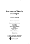
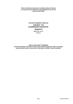
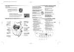
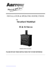
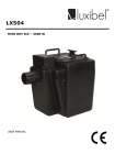
up to
Seas
effic onal
ie
(gros ncy
s)
Hamworthy Purewell VariHeat
High Efficiency, Fully Modulating Boilers
Condensing & Non Condensing
Cast Iron, Pre-mix, Modular Gas Fired
Single Boiler Outputs 65kW to 180kW
High Efficiency, Condensing
& Non Condensing
Fully Modulating, Pre-mix
Modular Gas Fired Boilers
The Purewell VariHeat is the simple direct
replacement for cast iron atmospheric boilers,
with low emissions and durability built in as
standard. All models comfortably exceed the
minimum seasonal efficiency requirements for
the Building Regulations (Amendment 2006),
making the Purewell VariHeat the perfect
choice for existing buildings
and new buildings.
Occupying the same small space as its
predecessors, but with up to 50% more
output, the Purewell VariHeat is a high
efficiency boiler range that can suit
condensing or non condensing systems,
and is available in 5 condensing models with
outputs from 70kW to 180kW, and 4 non
condensing models, 65kW to 125kW.
Purewell VariHeat boilers feature a control
system that uses an LPB bus communication
system, which simplifies the controls
requirements. Clip-in modules integrate the
boiler and building control capabilities with
an extensive range of options which include
boiler sequencing for up to 12 boilers
in a multiple boiler installation.
Energy saving high efficiency performance
Models for 11°C ∆t and 20°C ∆t systems
Robust cast iron heat exchanger
Simple design, reliable performance
Tolerant of older heating systems
Fully assembled for faster installation
Close control and accurate load matching
Purewell VariHeat is the fully compliant
direct replacement for cast iron
atmospheric boilers, with 50% more
output, matched system temperatures
and comprehensive controls capability.
Completing the Purewell VariHeat
package is a range of optional pipework
kits to simplify design and procurement.
The pipework kits are available for 2, 3 or 4
multiple boilers and are factory tested and
part assembled for ease of installation.
Options
Boiler sequencing
cascade controller
Room sensors
LPB bus communications
modules
Outside air sensor
Zone controller
DHW cylinder sensor kit
Pipework header kit
Purewell VariHeat high efficiency condensing boilers with a Dorchester DR-FC
condensing water heater.
2
BENEFITS
Purewell VariHeat
Specification
Purewell VariHeat
Natural Gas
Hamworthy have designed the Purewell
VariHeat to retain all the benefits
of traditional boilers, but with vastly
improved performance to more than
meet the performance requirements
for modern day boilers.
Purewell VariHeat boilers can be used as
single boilers, or as modules in a multiple
boiler installation. Each boiler is equipped
with a pre-mix down firing burner, cast iron
primary heat exchanger and a control panel,
all enclosed in a stylish factory fitted casing.
As a modular boiler, the Purewell VariHeat
can be installed with up to six boilers on
a single flue header, condensing outputs
reaching 1080kW, and centres are the
same as the Purewell and UR predecessors,
simplifying replacement. The boilers are
suitable for use in open vented or pressurised
systems and have a maximum working
pressure of 7 bar.
Flue System
The Purewell VariHeat is a high efficiency boiler, and like all other high
efficiency appliances, requires a water tight flue system that will retain
condensate whilst working under positive pressure.
The boiler is fitted with a primary flue connection directly into the base
assembly. The connector is fitted as standard with a tri-lip full ring silicone
seal which is impervious to water and vapour, ensuring a water tight flue joint.
It is compatible with the Hamworthy Masterflue range of stainless steel
flue components which are available in single or twin wall formats,
and can be interchanged to provide a safe and effective flue system.
Refer to page 26 for more details.
A fixed draught diverter is not required in the flue system, however,
a draught stabiliser is recommended for some installations.
Flue Terminal Location
Purewell VariHeat condensing boilers will produce condensate due to their
high thermal efficiency. The effect of this condensate production is to produce
pluming from the flue terminal, and careful consideration must be given to
the location of the flue terminal. Should pluming be a concern, then the flue
system should be designed to discharge at high level so as not to cause
a visual intrusion to the building occupants.
Construction
A down firing fully modulating gas burner
is fitted on top of the primary cast iron heat
exchanger and on the condensing models,
a secondary heat exchanger is positioned
in the base of the boiler to maximise heat
recovery from the flue gases.
The boilers are delivered fully assembled,
but for plant rooms with difficult access,
it is a simple task to separate the individual
sections for easier handling.
The boilers are finished externally using steel
side panels and stylish moulded plastic front
and top covers, which give excellent access
for servicing and maintenance.
Performance
Purewell VariHeat condensing boilers
achieve a full load efficiency up to
93.7% gross (104% nett), whilst at part
load the efficiency rises to 97.5% gross
(108% nett). This equates to seasonal
efficiencies up to 96% gross.
The high efficiency non condensing
models achieve seasonal efficiencies up
to 91% gross, exceeding the Building
Regulations minimum seasonal efficiency
requirements of 84% gross, for new
buildings and existing buildings.
Condensate Discharge
The condensate drains safely into the base assembly and a 32mm diameter
drain connection is provided, to run in standard plastic waste piping.
This condensate drain must be connected to a suitable drainage system,
typically as shown above. The material should be a suitable PVC plastic
system with sealed joints to prevent the escape of condensate.
Drain traps and an open tundish should be incorporated into the design,
and the pipework given appropriate protection from physical damage.
The pipework should be installed with at least a 3 degrees fall
(approximately 50mm per metre).
All boilers achieve European Class 5
performance for NOx emissions.
3
Specification
Purewell VariHeat
Natural Gas
Primary Heat Exchanger
Reduced Boiler Weight
Each boiler has a cast iron primary heat
exchanger arranged with horizontal sections,
connected at one end only to allow expansion
and contraction, retaining a proven
horizontal series water flow for even
hydraulic distribution.
Purewell VariHeat boilers have been reduced in weight significantly,
in comparison to traditional atmospheric cast iron boilers, with weights as
low as 1.3 Kg/kW output. The new casting designs are extremely efficient
therefore fewer sections are required to produce the given boiler outputs.
The primary heat exchanger is fitted
on top of the base assembly, which
encloses the secondary heat exchanger
on the condensing models.
Fan
Gas Valve
The high efficiency non condensing
models are designed for a traditional
11°C ∆t temperature rise and have a
minimum return temperature of 50°C.
Pre-mix down
firing burner
Secondary Heat Exchanger
Condensing performance is achieved
by returning the system water through a
copper/aluminium composite construction
secondary heat exchanger and extracting
the latent heat from the flue gases in
the base of the boiler. In keeping with
most modern high efficiency boilers, the
condensing heat exchanger is designed for
20°C ∆t temperature rise, with minimum
flow temperature of 40°C, maximizing the
opportunity for condensing performance.
Primary heat
exchanger cast iron
sections
Burner
The Purewell VariHeat features a fully
modulating pre-mix burner control system.
An electronic thermostat monitors the boiler
operating conditions and automatically
adjusts the output to suit.
The gas/air ratio control system ensures that
clean and efficient combustion is maintained
throughout the maximum modulation range,
down to a minimum of 20% capacity.
The plaque burner is positioned centrally
above the primary heat exchanger and is
constructed using a FeCrAl Aconit woven
mesh. This design of burner allows for
good flame stability at low turndown rates.
The woven fibre construction of the burner
also results in lower flame temperatures
being achieved and lowering NOx emissions.
Base assembly
Secondary heat exchanger
- condensing models only
Purewell VariHeat - heat exchanger arrangement, PV 180c
4
Boiler Thermostats
Pipework kits include:
Purewell VariHeat boilers are fitted with
a manual reset limit thermostat, which
has a range of 90-110°C on all models.
This will be factory set to 100°C.
n
Condensing boilers have an electronic control
temperature range 30-90°C, whereas the
high efficiency non condensing models
have a range from 50-90°C.
n
The electronic temperature control thermostat
regulates the boiler flow temperature up to
a maximum setting of 90°C.
n
n
n
Isolating ball valves for water flow, return and gas inlet connection
on each boiler, flow isolation uses a three port vent valve to prevent
fully sealing the boiler when isolated
Flow and return headers
Pre assembled flow and return pipe sub assemblies between boilers
and headers. Connections for gauges, sensors, safety relief valve, feed and
vent pipes (gauges, instrumentation and safety relief valves not included)
Blanking flanges for header ends
Support legs
To accommodate multiple boiler installations,
the limit thermostat is adjustable up to a
maximum of 110°C, however where the
boiler control thermostats are to be set
higher than 83°C, adequate system pressure
must be available either by gravity head
or system pressurisation.
Refer to page 20 for applications and system data.
The boiler also incorporates a return
temperature sensor, which in conjunction
with the flow temperature sensor, governs
the modulation set point of the boiler.
Pipework Kits
Designed to save time and simplify
procurement, optional pipework kits
are available from Hamworthy.
The kits enable multiple boilers to be
connected in configurations of 2, 3
and 4 boilers. The pipework kits are
factory tested and supplied part
assembled for ease of installation.
Purewell VariHeat-pipework assembly
Non Condensing Outputs @ 82/71°C flow/return temperatures
Boiler Model
PV 65he
Min
output
kW
1
2
3
4
5
6
7
8
21.5
65
130
195
260
325
390
455
520
Heat output according to number of modules installed - kW
PV 85he
30.1
85
170
255
340
425
510
595
680
PV 105he
33.6
105
210
315
420
525
630
735
840
PV 125he
39.8
125
250
375
500
625
750
875
1000
Condensing Outputs @ 50/30°C flow/return temperatures
Boiler Model
PV 70c
Min
output
kW
1
2
3
4
5
6
7
8
23.3
70
140
210
280
350
420
490
560
Heat output according to number of modules installed - kW
PV 95c
31.7
95
180
285
380
475
570
665
760
PV 110c
36.7
110
220
330
440
550
660
770
880
PV 140c
46.7
140
280
420
560
700
840
980
1120
PV 180c
60.0
180
360
540
720
900
1080
1260
1440
5
Technical Data he Models
Purewell VariHeat High Efficiency Non Condensing Boilers
Performance and General Data Information - Natural Gas
Boiler Model
PV65he
PV85he
PV105he
PV125he
(%) gross
86.97
87.34
88.10
87.00
Boiler output 82/71°C kW
Btu/hr x 1000
65.0
222
85.0
290
105.0
358
125.0
426
Boiler input - (gross) - maximum kW
Btu/hr x 1000
80.1
273
107.5
367
128.0
437
154.3
526
Boiler input (nett) - maximum kW
Btu/hr x 1000
72.1
246
96.8
330
118.1
403
139.8
477
Boiler output minimum 82/71°C kW
Btu/hr x 1000
21.5
73
30.1
103
33.6
115
39.8
136
Energy
Building regulations - seasonal efficiency Water
Water content System design flow rate @ 11°C ∆t rise l/s
Water side pressure loss @ 11°C ∆t rise mbar
Minimum flow rate @ 15°C ∆t rise l/s
Water side pressure loss @ 15°C ∆t mbar
Minimum return temperature Maximum water pressure Gas
Gas flow rate natural gas (G20) Flue
6
1.41
1.85
2.28
2.71
50
80
192
270
1.04
1.36
1.67
2.00
28
47
98
149
12.49
14.79
°C
50
barg
7
m3/hr
7.63
10.24
mbar
20
Maximum gas inlet pressure natural gas (G20) mbar
25
m3/hr
103.00
123.50
156.00
188.00
158
190
146
175
Approx flue gas temperature @ 82/71°C °C
Pressure at flue outlet Pa
100
Water flow/return connections inches
R 2”
Gas inlet connection pipe thread size inches
R 1”
mm
100
Nominal flue diameter (I/D) Electrics
Electrical supply
Power consumption - maximum modulation Start current Approx shipping weight Noise emission @ 1m - maximum modulation 6
9
Nominal inlet pressure natural gas (G20) Approx. flue gas volume @ 15°C - 9.3 - 9.8% CO2 @ N.T.P Connection
litres
230V 50Hz 1Ph
W
94.3
207
Amp
0.54
0.6
kg
205
277
MAX dB (A)
53
65
Technical Data c Models
Purewell VariHeat Condensing Boilers
Performance and General Data Information - Natural Gas
Boiler Model
PV70c
PV95c
PV110c
PV140c
PV180c
(%) gross
95.35
95.62
95.89
95.74
94.63
Boiler output 80/60°C kW
Btu/hr x 1000
63.5
217
86.3
294
98.8
340
134.4
448
172.8
590
Boiler output 50/30°C kW
Btu/hr x 1000
70
239
95
324
110
375
140
478
180
614
Boiler input - (gross) Maximum kW
Btu/hr x 1000
72.2
246
98.4
336
115.0
392
151.3
516
194.6
664
Boiler input (nett) - Maximum kW
Btu/hr x 1000
65.0
222
88.6
302
103.5
353
136.3
465
175.2
598
Boiler Output Minimum 80/60°C kW
Btu/hr x 1000
21.2
72
28.8
98
33.3
113
44.8
153
57.6
197
Boiler Output Minimum 50/30°C kW
Btu/hr x 1000
23.3
80
31.7
108
36.7
125
46.7
159
60.0
205
Energy
Building regualtions - seasonal efficiency Connection
Flue
Gas
Water
Water Content System design flow rate @ 20°C ∆t rise l/s
Water side pressure loss @ 20°C ∆t rise` 8
11
0.836
1.135
1.314
1.672
2.15
mbar
32
52
72
134
221
System design flow rate @ 11°C ∆t rise l/s
1.5
2.1
2.4
3.0
3.9
Water side pressure loss @ 11°C ∆t rise mbar
96
176
244
442
731
Maximum water pressure barg
14.42
18.541
137.16
180.53
232.12
7
Gas flow rate natural gas (G20) - maximum m3/hr
Nominal inlet pressure natural gas (G20) - maximum mbar
20
Maximum gas inlet pressure natural gas (G20) mbar
25
Approx. flue gas volume @ 15°C - 9.3 - 9.8% CO2 @ N.T.P m3/hr
6.88
9.375
86.13
117.37
10.956
Approx. flue gas temperature @ 50/30°C °C
40
45
50
50
Approx. flue gas temperature @ 80/60°C °C
60
65
70
75
Pressure at flue outlet Pa
100
Water flow/return connections inches
R2”
Gas inlet connection pipe thread size inches
R1”
mm
150
Nominal flue diameter (I/D) Electrics
litres
Electrical supply
Power consumption - maximum modulation Start current Approx shipping weight Noise emission @ 1m - maximum modulation 230V 1Ph 50Hz
W
94.3
207
Amp
0.54
0.6
kg
170
230
MAX dB (A)
53
65
7
Dimensional Details he Models
Purewell VariHeat High Efficiency Non Condensing Boilers
Single Boilers Without Pipe Kits
Dimensions in mm
Flow connection Return connection A
B
PV65he & PV85he
PV105he & PV125he
775nom
401nom
908nom
330nom
# Do not run trunking or pipework accross the top
of the boiler. Access is required top and front
for servicing.
Multiple Boilers With Pipe Kits
Dimensions in mm
Flow connection Return connection C
D
PV65he & PV85he
PV105he & PV125he
1650nom
1400nom
1780nom
1540nom
* Electrical trunking may be run in front
of the boiler at floor level, below the
front cover. (not HHL supply).
8
Dimensional Details c Models
Purewell VariHeat Condensing Boilers
Boilers Without Pipe Kits
Dimensions in mm
Flow connection PV70c, PV95c & PV110c
PV140c & PV180c
651
780
A
# Do not run trunking or pipework accross the top
of the boiler. Access is required top and front
for servicing.
Boilers With Pipe Kits
Dimensions in mm
PV70c, PV95c, PV110c, PV140c
PV180c
Flow connection C
Clearance G
Header centre line D
Header extremity E
Pipe flange to BS4504 H
1650
631
430
530
DN80 (3”)NB PNI6
1700
685
465
590
DN125 (5”)NB PNI6
* Electrical trunking may be run in front
of the boiler at floor level, below the
front cover. (not HHL supply).
9
Controls Overview
Purewell VariHeat
Purewell VariHeat boilers can be installed
in a wide variety of configurations, from
single boiler stand alone units to multiple
boilers controlled locally or by a building
management system. The controls package
is extremely versatile and can be tailored to
meet the exact needs of the heating system.
Integrated Systems
The full benefits of installing high efficiency
boilers can only be realised if the heating
system is equipped with appropriate controls,
that integrate the boiler and the other system
components, to create a cohesive solution.
For that reason, the Purewell VariHeat range
of boilers incorporate a control system that
is easy to integrate and communicates with
the leading building management system
protocols. The microprocessor based boiler
control system (LMU) accommodates clip-in
modules providing relay contacts for remote
alarm and signalling, for external control
and LPB bus communications, for use with
the boiler Cascade controller for multiple
boiler installations.
Volt Free Contacts
All Purewell VariHeat modules are fitted with a multi-function clip-in module
to provide volt free contacts as standard. Remote alarm signalling is provided
for a general fault alarm and bolier normal run indication.
0-10 Volt DC Analog Input
The standard multi-function clip-in module also provides a 0-10 volt DC
analog signal interface to control the modulation level of the burner, or to
set the flow temperature set point. The 0-10 volt signal can be used for
remote connection of the boilers to a Building Management System,
(BMS) to enable modulating control remotely.
LPB Bus Communications Module
The optional LPB bus communication clip-in kit is used to connect the boiler
LMU control unit to the optional Cascade sequence control module.
Each boiler in a modular installation requires a clip-in LPB bus
communications module to communicate with the Cascade controller.
Outside Air Temperature Sensor
Purewell VariHeat boilers can be supplied with an optional outside
temperature sensor to exploit the full functionality of the boiler controls
and enable direct temperature compensation on the boiler, maximising the
condensing operating conditions. The outside temperature sensor is to be
used in conjunction with the optional Cascade control module.
When fitted with an outside temperature sensor, the boiler’s own thermostat
is overridden and the flow temperature is controlled as a function of external
temperature conditions. The flow temperature is adjusted according to a
preset heating curve built into the standard boiler controls. This slope can be
adjusted to suit the needs of individual systems by for example using
a steeper slope on underfloor heating systems.
Programmable Room Sensor
An optional combined room sensor and digital programmer can be connected
to the boiler to provide both temperature control of ambient conditions
and to programme up to three daily periods for heating or hot water.
Note: An outside sensor must be used when using the room sensor and
programmer. Separate ambient temperatures can be set for each time period
with an override facility, enabling the user to switch the system either on or
off at their request. The programmer will display the current system operating
parameters and also indicate any boiler fault conditions that might occur.
Clip in modules on the LMU
The Purewell VariHeat boiler incorporates
a number of inbuilt and optional controls
features that enable the end user to achieve
desired operational mode whilst maintaining
the optimum efficiency of the system.
The controls are housed within a fabricated
steel enclosure, and each module fascia
features a visual display allowing the user to
monitor the current operating status of the
boiler. The panel also displays comprehensive
fault code information in the unlikely event
of a boiler lockout.
10
Frost Protection
The boiler control system features a two stage frost protection system.
When the boiler is not operating, the frost protection system fires
the boiler to maintain a minimum water temperature, to prevent
freezing of the heating system water.
Additionally, if an external temperature sensor is connected, the circulation
pump will be run intermittently when the outside temperature falls below 1.5°C.
Cascade Control Module
For use with multiple boilers, the optional Cascade controller can sequence
up to 12 modules. The controller is supplied with two clip-in LPB bus
communications modules as part of the standard Cascade kit, and for
each additional boiler in the modular installation, further clip-in LPB bus
communications modules must be ordered separately. (IE: A four module
installation with a Cascade control kit requires two additional LPB modules).
Control Details
Purewell VariHeat Single Boiler Installations
On Purewell VariHeat boilers, the control
options for single boilers are different to
those for multiple boilers.
Options for a single Boiler only
Please refer to page 12 for controls on
multiple boilers.
Programmable room sensor (QAA73)
Outside air sensor (QAC34)
2nd Heating Circuit Clip-in relay kit (AGU2.500)
DHW Cylinder Sensor Kit (QAZ21)
All controls functions are managed via the
‘boiler management unit’ Siemens LMU64.
Using a combination of options, the level
of control is expandable for up to 2 heating
circuits and 1 domestic hot water cylinder.
A circulation pump overrun timer is
incorporated within the boiler LMU.
Programmable Room Sensor
A single boiler Purewell VariHeat system
can be fitted with a single programmable
room sensor, which should be located in
the first heating zone. This room thermostat
allows heating circuit management to be
based on both the internal and external
air temperature. The boiler will manage
the heating circuit pump via a contactor
according to the program requirements
of the programmable room unit.
Features:
n Individual
7 day program with auto
summer / winter hour change for heating
circuit 1, heating circuit 2 and DHW
n 3 periods per day per time program
n Constant or variable temperature flow
n Compensated flow temperature based on
external and room air temperatures
n Optimised start / stop based on external
and room air temperatures
n Building frost protection based on
room air temperature
n Summer shutdown based on
outside air temperature
n Holiday period with frost protection
n Reduced temperature, night set back
for non occupancy hours
n Pump kick for pumps controlled
from boiler
n Programme lock to prevent tampering
n Individual temperature settings
for each zone
To achieve full functionality an outside air
sensor must be fitted.
Outside Air Sensor
An optional outside air temperature sensor may be wired directly to the boiler
to exploit the direct weather compensation functionality of the boiler controls.
This sensor may be connected to the control scheme and should ideally be
positioned on an external wall with northerly aspect.
2nd Heating Circuit Clip-in Relay Kit
To control a second heating circuit, an additional clip-in relay kit is required
for fitting directly to LMU. The kit comprises a relay and water temperature
sensor complete with pocket.
This kit provides outputs for a pump and mixing valve.
n
n
n
n
n
n
Mixing valve allows second heating circuit to operate at a different
temperature set-point to heating circuit 1.
Second heating circuit should operate at the same or lower temperature
than circuit 1, e.g. underfloor heating.
Programmed via QAA73 programmable room sensor
Compensated flow based on outside air temp and using a curve separate
to that of heating circuit 1 owing to mixing valve
Optimised start/stop based on outside air temp
Frost protection based on water temperature in second heating circuit
For the second heating circuit, the boiler will manage the circuit pump and/
or mixing valve via contactors, according to the program requirements of
the programmable room sensor and the water temperature sensor. Only one
programmable room sensor may be connected, therefore the second
heating circuit management is derived from time control and external air
temperature measurement.
DHW Cylinder Sensor Kit
This kit is for a domestic hot water (DHW) circuit directly controlled from the
boiler, but programmed via the QAA73 programmable room sensor, and
features:
n
Immersion sensor complete with pocket
DHW cylinder sensor and pump output directly from boiler LMU
n Frost protection based on stored water temperature
n Reduced storage temperature for non-occupancy hours
n Anti-Legionella function
n
For the DHW cylinder circuit, the boiler will manage the primary coil pump
according to the program requirements of the programmable room unit and
the DHW cylinder sensor.
11
Control Details
Purewell VariHeat Multiple Boiler Installations
On Purewell VariHeat boilers, the control
options for multiple boilers are different
to those for single boilers.
Options for Multiple Boilers only
Boiler sequencing cascade controller (RVA47)
LPB bus communications Clip-in module (OCI420)
Programmable room sensor (QAA70)
Outside air sensor (QAC31)
Room sensor non-adjustable (QAA10)
Room sensor offset adjustable (QAA50)
Zone controller (RVA46)
DHW Cylinder Sensor Kit (QAZ21)
Please refer to page 11 for controls
on a single boiler.
The Purewell VariHeat boiler in a multiple
boiler installation may be controlled by a
boiler sequencing cascade controller. This
provides cascade control from either external
enable signals or from internal time clock
settings. Up to 12 boiler modules may be
controlled and communication between the
cascade controller and boilers is via an LPB bus.
The boiler sequencing cascade controller is
a sophisticated controller which, when used
with a room temperature sensor and outside
air sensor, will provide enhanced comfort
control for the heating zone it is connected to.
LPB Bus Communications Clip-in Module
Additionally a domestic hot water cylinder
circuit may also be controlled from the boiler
cascade controller.
Boiler Sequencing Cascade Controller
Where the building has more than one
heating zone, additional zone controllers
can be added to provide a comprehensive
building heating control.
Programmable Room Sensor
The programmable room sensor
communicates room temperature to the
RVA47 Cascade Controller and allows the
user full adjustment of the room temperature,
time clock, holiday periods and frost
protection settings. The unit also displays fault
codes from the boiler plant. Alternatively, non
adjustable and offset adjustable room sensors
are also available, for installations requiring
users to have less access to system settings.
Features:
n
n
n
n
n
n
3 programmable periods per day
Reduced temperature/night set back for
non occupancy hours
Holiday period. Frost protection remains
active
Programme lock to prevent tampering
Indication of operating parameters and
boiler fault condition
7 day time clock with automatic summer/
winter clock adjustment
1 clip-in module is required for every boiler in a multiple boiler arrangement.
Two clip-in modules are supplied as part of the Boiler Sequencing Cascade Controller
kit, so for three boilers or more, additional clip-in modules must be ordered.
Multiple Purewell VariHeat boilers can be sequenced using this cascade
control kit. The kit includes:
n
RVA47 controller
Insertion type water temperature sensor with pocket
n Two clip-in LPB bus communication modules*
n
* Note: When controlling more than two boilers, then additional
clip-in LPB bus communication modules must be ordered separately.
(I.e. A four boiler installation with a cascade control kit requires
two additional LPB bus communication clip-in modules)
Features:
n
n
n
n
n
n
n
n
n
n
n
n
n
n
n
Provides cascade control from either external enable signals, 0-10v
analogue heat demand signal or built-in time clock setting
Up to 12 boilers may be sequenced
Lead boiler rotation
7 day time clock with automatic summer/winter clock adjustment
3 programmable periods per day
Constant or variable temperature flow
Compensated flow temperature based on external and room air temperatures
Optimised start and stop based on external and room air temperatures
Frost protection based on boiler water temperature
Building frost protection based on room air temperature
Summer shutdown based on outside air temperature
Holiday period. Frost protection remains active
Reduced temperature/night set back for non occupancy hours
Pump kick for pumps controlled from boiler
RVA47 controller is designed for mounting in a remote panel (not HHL supply)
To achieve full functionality an outside air sensor must be fitted.
The boiler cascade will operate according to the integral seven day time
clock with automatic summer/winter hour change. Three time periods are
programmable for each day. When there is no time demand, the boiler will
revert to the reduced temperature / night set back set-point, provided a room
temperature sensor is fitted. Otherwise the cascade will not operate unless
the frost protection function of the boiler and/or cascade is activated.
12
Outside Air Sensor
Zone Control
To be used with cascade controller,
the optional outside temperature
sensor must be wired directly to the
cascade controller to exploit the full
control functionality, including
weather compensation.
Additional to the cascade control,
multiple heating zones can be
connected into the system to provide
a comprehensive building control.
Each zone has an individual 3 program
timer, which together with outside
and inside air temperature sensors can
provide optimised start/stop for that
circuit.
This sensor must be connected
to the control scheme and must
be positioned on an external wall
with northerly aspect.
Room Sensor Non Adjustable
For installations where controls
are not to be adjusted by the
building occupants, the QAA10 non
adjustable room sensor may be used.
This prevents tampering and
communicates room temperature
to RVA47 Cascade Controller.
No user adjustment is possible.
Room Sensor Offset Adjustable
For installations where limited control
is required by the building occupants,
the QAA50 offset adjustable room
sensor ay be used. This permits
adjustment +/- 3°C from the
programmed temperature set point
and communicates room temperature
to RVA47 Cascade Controller.
Zone Controller
Multiple heating zones may
be connected into the system
to provide a comprehensive
building control.
A zone controller and sensors
are required for each zone.
Control Features:
n
n
n
n
n
n
n
n
3 programmable periods per day
Optimised start / stop
Constant or variable temperature
Pump output to control zone pump
via relay/contactor (not HHL supply)
Mixing valve output
Reduced temperature/night set back
for non occupancy hours
Frost protection
7 day time clock with automatic
summer/winter clock adjustment
Using the RVA46 controller, zones
can be configured for either constant
temperature or variable temperature.
Heat demand is calculated according
to zone air temperature and where
applicable outside air temperature.
Using the same compensation heat
curves and parallel displacement curves
as the cascade controller (shown on
page 15), each zone can be configured
to operate individually from any other
zone in the system. Individual night set
back and frost protection settings as
well as summer shut down settings can
also be programmed.
Demands for heat are communicated
to the cascade controller via the LPB
bus to initiate heat generation when
required. The cascade will set the
primary circuit operating temperature
according to the highest heat demand,
therefore where multiple heating zones
are used, these are best configured
as variable temperature circuits
making use of the zone controller
mixing valve outputs. This way, when
differing heat requirements exist across
multiple zones, the lower temperature
zones can modulate the mixing
valve to maintain water temperature
requirements.
sensors are used as for the cascade
controller. External air temperature
is communicated via the LPB from
the sensor connected to the cascade
controller.
Each zone controller also has a DHW
time program which can be used
to initiate the cascade controller for
hot water production. Using the
same cylinder as the cascade circuit,
the cascade will produce hot water
whenever there is a hot water demand
from one of the zones or from the
cascade controller integral hot water
time program providing a central hot
water facility.
Domestic Hot Water
A domestic hot water cylinder may be
connected to the cascade controller.
With the immersion temperature
sensor connected directly to the
cascade controller, hot water will be
produced whenever there is a demand
within the timer programmed periods.
The hot water circuit is provided with
its own three period time clock, and
also has a separate night set back
feature, frost protection and an anti
legionella function.
The primary circuit to the calorifier
is controlled using the domestic hot
water pump output which is energised
only when a hot water demand
is present. This pump should be
connected to the controller via
a relay contactor.
Each zone control has a pump output
that can be used to control the zone
pump via a relay/contactor. When a
heat demand exists within the zone,
the pump will be started until the
demand for heat is satisfied.
An individual room air temperature
sensor is required in each zone. The
same selection of room temperature
13
Multiple Boilers
With Modulating Burners
Optimising Life Time Performance
In addition to providing system security,
accurate load matching is one of the major
advantages of using multiple boilers.
When first introduced, modular boilers
operated in a basic mode, where modules
were switched on or off to meet the
system demand for heat. The requirement
for turndown was met by increasing
or decreasing the number of modules
(boilers) in an installation.
As boiler designs advanced, two stage
modular boilers became more popular,
and high/low firing boilers changed the
parameters for turndown.
Today, most high efficiency boilers have fully
modulating capability and this once again
changes the methodology for achieving close
control in a multiple boiler installation.
When selecting modulating high efficiency
boilers, consideration should be given to the
life time costs associated with service and
maintenance of the boilers. Opt for too many
small output (kW) boilers and the servicing
costs will be higher, whereas too few large
output (kW) boilers will result in less back
up and system security.
It is important therefore to select the
optimum size boiler output and number
of modules to achieve a balanced life time
cost and ensure system security.
In practice, heating systems rarely operate at full load conditions and so
configuring the system to optimise the part load performance is an effective
way of maximising the energy saving of the heating plant.
Purewell VariHeat Boiler Sequencing Cascade Controller
The boiler sequencing cascade controller available with Purewell VariHeat boilers
can be configured to sequence boilers in traditional cascade mode or in unison mode.
Cascade Control
Steps a boiler module on at its lowest rate and then modulates it to its
maximum rate, before switching on the next boiler module at its lowest rate,
to match the system load. Maintains the lowest number of boiler modules in
operation for a given heat load.
Unison Control
Steps each boiler module on in turn at its lowest rate, then modulates all
boiler modules simultaneously to higher rates to match the system load.
This method of sequencing can offer higher operating efficiencies, taking
advantage of the higher part load efficiencies available at low firing rates.
Using BMS Signals to Initiate Cascade
Temperature control 0 -10 Volt DC analog input.
The cascade controller can be configured to accept a BMS analog input to
initiate heat generation. Where analog inputs are used, the cascade controller
provides heat generation according to the magnitude of the input signal only.
NOTE: When using the BMS to initiate cascade control via a 0-10 volt analogue
signal, then the internal time clock and remote enable circuit functions are
disabled. Input signals to the RVA47 cascade control must be temperature
configured. The input signal is translated to a temperature set-point for the
flow temperature, and translation is according to a linear graph from 5°C to
an upper limit set by parameters during commissioning. 10 Volts corresponds
with the upper limit with a maximum 90°C setting.
The Hamworthy range of Purewell VariHeat
boilers has been designed to satisfy a wide
range of commercial systems. Available as
condensing and non-condensing boilers,
with fully modulating burners, multiple
boiler applications enable accurate load
matching using the optimum number
of boiler modules.
Each module (boiler) can modulate
to part load conditions, where efficiency
performance will be the greatest.
Setting the boiler sequence controller
to fire each boiler at low fire before
modulating up to high fire will not only
provide the best efficiency performance,
but also enable the boilers to share the
system load and even out wear
and tear on the plant.
14
When there is no analog input, the boilers will not fire unless the frost protection
function of the boiler is activated. It is recommended that the BMS has a frost
protection setting higher than 5°C water temperature, to prevent the boiler
from firing without circulation. Please refer to the section on pump control, page 15.
Whilst operating with an analog input signal, the cascade controller will
provide lead boiler rotation programmable for number of hours run.
Weather Compensation
Room Temperature Set Point
When using an external air temperature sensor with remote enabled systems
(not 0 – 10 Volt) or integral time clock, the flow temperature can be
directly compensated. The heating curve corresponding to the required flow
temperature conditions is fully adjustable with curve settings from 2.5 to 40.
The required room temperature is set from
the cascade controller and the actual room
temperature communicated to the cascade
controller from a remote room
temperature sensor.
Primary Circuit Pump Control
In all installations it is recommended that the
primary circuit pump start signal is provided
from the boilers. Each boiler has a shunt
pump output and these should all be wired
together in parallel to energise the pump
relay contactor. It is important that all boilers
are connected to the same supply phase, as
mixing phases could lead to higher voltages
present in the pump circuit than required. By
energising the primary pump via the boilers,
the boilers are prevented from firing without
circulation, in frost protection mode.
To further enhance comfort levels within the building, when used in conjunction
with a room temperature sensor, the cascade flow temperature set-point will be
adjusted, dependent on the actual room temperature. I.e. if the room temperature
is high then the control will further reduce the flow temperature automatically.
Further enhancements for comfort can be made using the offset adjustment for the
heating curve, programmable to reset the curve parallel to the original +- 4.5°C
Should control of the primary pump be
required from an alternative source, such as
a BMS system, then the frost protection set
point for starting the primary pump should
be higher than 5°C water temperature.
This will ensure that the primary pump
will have started before the boilers can
operate under the influence of their integral
frost protection, which is set at 5°C water
temperature.
Interlocks
Remote interlocks, e.g. pressurisation unit,
flue fans etc can be connected directly to
each boiler module using the safety interlock
circuit input. Neither the RVA47 cascade
controller nor the RVA46 zone controller
have safety interlock circuit inputs.
Remote Start Stop
The RVA47 Cascade controller can
receive a remote start stop signal from an
external source. This signal must be via
a volt free contact. All time clock functions
including optimised start and stop must be
incorporated within the remote time clock
circuitry. The frost protection functionality
within the RVA47 Cascade controller
will always remain active.
15
Controls Scheme 1
Purewell VariHeat Boilers
Internal Time Clock Controlled System using RVA47
Pipework and Controls Schematic for Internal Time Clock Controlled Systems
RVA47 Wiring Schematic for Internal Time Clock Systems
These schematics are available to download at www.hamworthy-heating.com
16
Controls Scheme 2
Purewell VariHeat Boilers
External Switched Remote Enable with RVA47
Pipework and Controls Schematic for External Switched Enable Systems
RVA47 Wiring for Externally Enabled Systems
These schematics are available to download at www.hamworthy-heating.com
17
Controls Scheme 3
Purewell VariHeat Boilers
External 0-10 volt Enabled System with RVA47
Pipework and Controls Schematic for External 0-10v Enabled System
%KNVÄRDMRNQ
RVA47 Wiring Schematic for External 0-10v Enabled Systems
These schematics are available to download at www.hamworthy-heating.com
18
Controls Scheme 4
Purewell VariHeat Boilers
RVA47 Control of Primary Circuit, Time Control of Secondary Circuits using RVA46
Pipework and Controls Schematic
RVA47 Wiring Schematic
These schematics are available to download at www.hamworthy-heating.com
19
Application & System Data
Purewell VariHeat Boilers
The installation of the boiler MUST be in
accordance with the relevant requirements
of the Gas Safety Regulations, Building
Regulations, IEE Regulations and the bylaws
of the local water undertaking. It should
also be in accordance with any relevant
requirements of the local gas region
and local authority and the relevant
recommendations of the documents below.
The following British Standard Codes
of Practice and Regulations have relevant
recommendations regarding the installation
of Purewell VariHeat boilers.
British Standards
BS 5440.Part 1 Installation and maintenance
of flues for gas appliances of rated input not
exceeding 70kW net.
BS 5440.Part 2 Installation and maintenance
of ventilation for gas appliances of rated
input not exceeding 70kW net.
BS EN ISO 4126-1 Safety devices for
protection against excessive pressure.
Safety valves.
BS 6798 Installation of gas appliances rated
input not exceeding 70kW net.
BS 6644 Installation of Gas Fired Hot Water
Boilers, 70kW to 1.8MW net input.
BS 6700 Design, installation, testing and
maintenance of services supplying water
for domestic use.
BS EN 806-2 Specification for installations
inside buildings conveying water for human
consumption – Part 2: Design.
BS 6880 Part 1,2 & 3 Code of practice for
low temperature hot water heating systems
of output greater than 45kW
BS 7074 Part 1 Application, selection and
installation of expansion vessels and ancillary
equipment for sealed water systems.
Part 2 Code of practice for low and medium
temperature hot water systems.
BS 7671 Requirements for electrical
installations. IEE Wiring Regulations.
Sixteenth edition.
I. Gas E. Publications
IGE/UP/1 Soundness testing and purging of industrial and commercial gas
installations.
IGE/UP/1A Soundness testing and direct purging of small low pressure
industrial and commercial natural gas installations.
IGE/UP/2 Gas installation pipework, boosters and compressors in industrial
and commercial premises.
IGE/UP/10 Installation of gas appliances in industrial and commercial
premises, Part 1 flued appliances.
Health and Safety Executive:
Guidance note PM5 - Automatically controlled steam and hot water boilers.
CIBSE Publications
CIBSE
CIBSE
CIBSE
CIBSE
Guide B Heating, ventilating, air conditioning and refrigeration.
Guide H Building Control Systems
Guide Energy Efficiency in Buildings
Commissioning Code B: 2002
Dept. of the Environment, Scottish Development Dept. & Welsh Office.
1956 Clean Air Act Memorandum Third edition
Third Edition of the 1956 Clean Air Act Memorandum.
Department of the Environment, Scottish Development Department & Welsh Office.
Location
The location chosen for the boiler must permit the provision of a satisfactory
flue system and an adequate air supply. The location must also provide
adequate space for servicing and air circulation around each unit.
This includes any electrical trunking laid along the floor and to the appliance.
Any combustible material adjacent to the boiler and the flue system must be
so placed or shielded to ensure that its temperature does not exceed 65°C.
Further details regarding boiler location are given in BS 6644. & BS 5440 part 2.
Purewell VariHeat boilers should be positioned on a level non combustible
surface that is capable of supporting the boiler weight when filled with
water, plus any ancillary equipment. Adequate space should be allowed
for installation and servicing. Refer to dimensional drawings on pages
8 & 9 for more details.
Adequate Water Flow
The Purewell VariHeat boiler is designed as a quick response, low water
content unit to run continuously with minimal operating problems. Care
should be taken in the initial design and layout, having due regard for
adequate water flow through the boilers, and the influence of the control
system. Hamworthy strongly recommend that Purewell VariHeat boilers are
installed using the primary circuit design to ensure adequate water flow
regardless of secondary circuit operating conditions. Refer to technical data
tables for minimum water flow requirements.
The control system and valves, where fitted, should be regulated to avoid
lower flows occurring. Condensing models are designed to operate with
systems operating at 20°C differential temperatures and return temperatures
as low as 30°C. Increased flow rates may be used for lower temperature
differentials with due regard for the increased pressure loss through the boiler.
Non-condensing models are designed for more traditional systems operating
at 11°C differential temperatures and return temperature no lower than
50°C. Differential temperatures to a maximum of 15°C are acceptable.
20
Water Systems
Delivery
Purewell VariHeat boilers are suitable for both open vented or sealed
pressurised systems. Sealed systems must comply with Health and Safety
Document PM5 requirements for fuel supply cut off in the event of low and
high pressure conditions. To ensure compliance, consider using a proprietary
pressurisation unit with correctly sized expansion vessels.
Each boiler is despatched fully assembled
and factory tested with the casing and
control panel fitted. The boiler base has been
designed to accept a pallet truck allowing
easy manoeuvrability. The assembly is
protected with cardboard edging and
shrink wrapped for transportation.
In multiple boiler installations, the flow and return headers should be connected
in a “reverse return” arrangement (i.e. the water flow in each header follows
the same direction) thus providing equal flow through each boiler. This also
ensures that the pressure loss across any number of boilers will never be
greater than the head loss across one boilers plus local pipework losses.
System Feed Water Quality
If the boiler feed water has a high degree of hardness, it is recommended that
the water be treated to prevent precipitation of scale or sludge in the boiler
water passageways. Details of additives can be obtained from any reliable
manufacturer of water treatment products or the local water authority.
Open Vent Pipe and Cold Feed Pipe Data
Boiler
Open Vent Size
Cold Feed Size
The primary flue pipe is supplied
separately for fitting on site.
All Hamworthy products are delivered
to site on a tail-lift vehicle, and deliveries
are closely co-ordinated with the customer,
to suit the site construction programme.
Standard delivery is to ground level from
the tail-lift of the vehicle. To enquire about
special delivery services, please contact
our customer services team.
Commissioning
Pressure Relief Valve
Hamworthy Heating strongly recommend that
all boilers are commissioned by our service
department. On completion, Hamworthy will
issue a boiler log book which will provide
details of the initial operating settings.
The log book should be used to record any
future maintenance and service work.
Each boiler, or in the case of a modular installation, each bank of boilers,
must be fitted with a pressure relief valve to BS EN ISO 4126-1,
and sized as shown in BS 6644.
For more information on commissioning
contact Hamworthy Heating Service
Department: Tel 0845 450 2866.
Hamworthy can supply Purewell VariHeat pipe kits which have isolation valves
for each boiler, to enable individual boilers to be shut down from the system.
The pipe kit includes a three-port valve on the flow connection for each boiler,
enabling a single safety valve to be fitted to the connection on the header
pipework. Safety valves are not included.
Warranty
<60kW
60kW - 150kW
150kW - 300kW
300kW - 600kW
25mm (1 in)
19mm
(3/4
in)
32mm
(11/4
in)
25mm (1 in)
38mm
(11/2
in)
32mm (11/4 in)
50mm (2 in)
38mm (11/2 in)
Where these pipe kits are not used, each boiler must be fitted with a safety
valve in the flow pipework, positioned before any other valve in the system.
BS 6644 provides comprehensive information for the selection and location
of safety valves and attention is drawn to the higher capacity requirements
of safety valves for pressurised hot water systems.
Products from Hamworthy carry a standard
two-year warranty on parts, and where
the product is commissioned by Hamworthy
service engineers, then the warranty covers
parts and labour. In offering flexible solutions
for after sales support, Hamworthy can
tailor packages to suit individual customer
requirements, many of which include
extended warranty benefits.
21
System Head
Guidance Note PM5 Health and
Safety Executive
This note states that "hot water
boilers should have an automatic
control apparatus to cut off fuel to the
burners of gas fired plant when the
water at or near the boiler flow outlet
rises to a pre-determined temperature.
This should provide a margin of at
least 17°C below the temperature of
saturated steam corresponding to the
pressure at the highest point of the
circulation system above the boiler."
To comply with this recommendation,
the minimum system pressure is
dependant on system design flow
temperatures and in the case of
modular installations, the temperature
rise across each module.
Single Installations
The minimum pressure must be equal
to the gauge pressure equivalent to
the saturated steam temperature
obtained by adding 17°C to the
required boiler flow temperature. The
highest point of the circulation system
above the boiler should never be less
than 2m (6.5ft).
n Required flow
temperature 90°C
n Safety margin 17°C
n Equivalent saturated
steam temperature 107°C
From steam tables
corresponding gauge pressure
0.3 bar – 3.0m head of water.
Modular Installations
The minimum pressure should be
equal to the gauge pressure equivalent
to the saturated steam temperature.
This is obtained by adding 17°C to
the sum of the required mixed flow
temperature plus the temperature rise
across the modules.
n System Δt 11°C 20°C
n Required mixed flow
Temperature 82°C 80°C
n Temperature rise
across modules at
minimum flow rate 11°C 20°C
n Safety margin 17°C 17°C
n Equivalent saturated
steam temperature 110°C 117°C
n From steam tables
corresponding gauge
pressure
0.43 bar 0.80 bar
(4.40m) 8.20m)
From steam tables
corresponding gauge pressure
at 11°CΔt 0.43 bar, 4.40 m
From steam tables
corresponding gauge pressure
at 20°CΔt 0.80 bar, 8.2 m
Air Supply and Ventilation
An adequate supply of fresh air for
combustion and ventilation must be
provided in accordance with BS 6644.
The air supply should be free
from contamination such as
building dust and insulation
fibres from lagging. To avoid
unnecessary cleaning and
servicing of the burner, we
recommend that the boilers are
not fired whilst building work
is being undertaken.
The air supply should be achieved
using:
n Natural ventilation supplying air with a low level opening and discharge through a smaller sized high level opening.
n A fan to supply air to low level with natural discharge through
a high level opening.
n A fan to supply air to low level and discharged by means of a fan at a high level.
Note: Fans must be selected
such that a negative pressure is
not created in the boiler house
relative to outside air pressure.
The air supplied for boiler house
ventilation should be such that the
maximum temperatures within the
boiler house are as follows:
n At floor level 25°C
(or 100mm above the floor level)
n At mid level 32°C
(1.5m above floor level)
n At ceiling level
40°C
(or 100mm below ceiling level)
Where natural ventilation is used
suitable permanent openings at low
level and high level connected directly
to the outside air should be provided.
These openings must be fitted with
grilles that cannot be blocked or
flooded.
The free area of the grilles should be
as follows:
Low Level (Inlet)
4cm2 per kW of net heat input.
High Level (Outlet)
2cm2 per kW of net heat input.
Ventilation
Where a boiler installation is to
operate throughout the summer
months, e.g. for domestic hot water
production for more than 50% of
the time, then additional ventilation
allowances are required. Refer to
BS6644 for more detailed information.
The Building Regulations 2000
Conservation of fuel and power 2006 edition
Approved Document AD L2A New Buildings, other than dwellings
Approved Document AD L2B Existing Buildings, other than dwellings
These new regulations came into force 6 April 2006. Compliance with the latest regulations now requires a whole building
approach to reduction in carbon emissions. The 2006 edition requires the use of heat generating plant as detailed in the
supporting 2nd tier guide - Non Domestic Heating, Cooling and Ventilation Compliance Guide.
Seasonal Efficiency
The efficiency data used for evaluating commercial boilers is known as the heat generator seasonal efficiency and this guide
states that for new buildings and existing buildings, the minimum heat generating system seasonal efficiency is 84% gross for
natural gas.
The heat generator seasonal efficiency for Purewell VariHeat boilers exceeds the minimum requirement, Individual boiler figures
can be found on pages 6 & 7.
22
Primary Circuit Pump
Purewell VariHeat Boilers
Pumps for circulation through the boilers should be sized according to the flow rate
and pressure loss requirements for a boiler, or group of boilers, and associated local pipework.
For details of flow rate requirements and boiler pressure loss, please refer to data tables on pages 6 and 7.
Hamworthy Heating is the exclusive distributor of Biral pumps in the UK. With a wide range of models available,
you can closely match pump performance to suit your requirements.
The high quality design with innovative features include:
n
n
n
n
n
n
n
n
Unique Can system – no seals to leak
Low, medium and high speed ranges
High torque starting
Ultra low power consumption
Flat performance curves – less system noise
Operating pressures up to 16 bar
Temperatures from -20°C to 140°C
Whisper quiet pump operation
Matched Biral Pumps for 20°C Δt Primary Circuit - Condensing Purewell VariHeat Boilers
Model
PV
PV
PV
PV
PV
70c
95c
110c
140c
180c
1
MX12-3
MX13-3
LX323 or LX401*
LX402
LX403
Number of Boliers
2
3
LX323-2
LX326 or LX402*
LX325 or LX401*
LX403
LX326 or LX402*
LX503
LX503
LX652
LX504
LX653
4
LX403
LX503
LX504
LX653
LX654
Matched Biral Pumps for 11°C Δt Primary Circuit - Condensing Purewell VariHeat Boilers
Model
PV
PV
PV
PV
PV
70c
95c
110c
140c
180c
1
M14-2
LX326 - LX402*
LX503
HX402-1
HX502-1
Number of Boliers
2
3
LX403
LX504
LX504
LX653
LX653 L
LX654
HX502-1
L804 or HX652*
HX652
HX802
4
LX653
LX654
LX655
L805 or HX802*
L1003
Matched Biral Pumps for 11°C Δt Primary Circuit - Non Condensing Purewell VariHeat Boilers
Model
PV
PV
PV
PV
65he
85he
105he
125he
1
LX322-2
LX323-2
LX403
LX503
Number of Boliers
2
3
LX326 or LX401*
LX503
LX403
LX652
LX504
LX653
LX653
LX654 or LX802*
4
LX652
LX652
LX654 or LX802*
LX803
Matched Biral Pumps for 15°C Δt Primary Circuit - Non Condensing Purewell VariHeat Boilers
Model
PV
PV
PV
PV
65he
85he
105he
125he
1
LX321-2
LX323-2
LX323-2
LX502
Number of Boliers
2
3
LX325
LX326 or LX402*
LX326
LX503
LX403
LX504 or LX652*
LX503
LX653
4
LX503 or LX652*
LX652
LX652
LX653 or LX802*
* Matched pump selection depends on installation pipe size. Contact our technical department on 01202 662379 for guidance.
23
Wiring Diagram
Purewell VariHeat Boilers
The following electrical connections are provided on each module:
0DLQV 6KXQW3XPS 3RZHUHG /RFN2XW 1RUPDO5XQ
6XSSO\
2XWSXW
2XWSXW
Ya+]
5HPRWH $QDORJXH 2XWVLGH 6DIHW\LQWHUORFN
/3%%XV
2Q2II
LQSXW
VHQVRU OLQNLIQRWXVHG
LQSXWVLJQDO
3RZHUHG2XWSXW
%062XWSXW
2SWLRQ
25 2SWLRQ
&RQWDFWVUDWHG
9a+]0D[$
Electrical Connections
There is a gland plate fitted to the front of the boiler, at floor level, to accept cables for power supply and controls.
A single terminal rail is fitted inside the front cover, and all external connections are made to this terminal rail.
The plug-in terminal rail facilitates easy removal for improving access during servicing and maintenance.
Power Supply
An independent isolator and fused electrical supply is recommended for each boiler. Supply 230 volt, 50Hz, single phase.
Wiring external to the boiler must be installed in accordance with IEE Regulations and any local regulations which apply.
Wiring must be completed in heat resistant 3 core cable, (size 1.0 mm2 c.s.a.) Fascia fuse rating is 2 amp. External fuses
should be 6 amp for all single boiler sizes.
To prevent drawings excessive current (>1 amp) through the boiler control panel, it is recommended that pumps
are connected via contactors.
24
*URXQG
6ODYH
6LJQDO
*URXQG
9'&
*URXQG
9'&
*URXQG
a9
*URXQG
9'&
1RUPDO5XQ
/RFN2XW
%06,QSXW6LJQDO
1HXWUDO
/LQH2XW
1HXWUDO
/LQH2XW
n
1HXWUDO
n
/LYH
n
1HXWUDO
n
/LYH
n
1HXWUDO
n
Supply live neutral and earth
Supply input for boiler fault and normal run signals
Boiler fault alarm system signal output
Boiler normal run signal output
0-10v analogue control signal input
Remote on/off control input
Boiler shunt pump output
Safety interlock circuit input
/LYH
n
(DUWK
n
Wiring Diagram
Cascade and Heating Zone Controls
Controls Installation
The RVA46 and RVA47 controls are designed for panel
mounting. It is recommended that the controls are mounted
with the fascia exposed externally for ease of use.
Panel cut-out dimensions for RVA46 & RVA47 controllers
All electrical connections use polarised coloured screwed
terminal blocks to ensure that once installed and
commissioned, connections are easy to relocate in their
original position, if removed.
The LPB bus communication cable between controllers and
boiler can be extended to a maximum 1400 metres length.
Cable should be (non interchangeable) two core twisted
with 1.5mm2 CSA.
Room temperature sensors, QAA10, QAA50 and QAA70,
may be located up to 50 metres from their respective RVA
controller. Wiring between controllers and the room sensors
using 2 wire (interchangeable) cable. Max 1.5mm2 CSA.
External air sensor QAC34 may be located up to maximum
120 metres from the RVA controller. Usually connected to
the RVA47, wiring using 2 wire (interchangeable) cable.
Max 1.5mm2 CSA.
Water temperature sensors, QAZ21, may be located up
to maximum 120 metres from the RVA controller.
Wiring using 2 wire (interchangeable) cable. Max 1.5mm2 CSA.
Pump outputs are volt free contacts rated to 2 amps 230V
max. It is strongly recommended that pumps and mixing
valves are connected via contactors, where higher running
currents will be experienced.
The mechanical mounting allows fitting in panel
fronts that have a thickness of 2mm to 10mm.
25
Flue System
Purewell VariHeat Boilers
Purewell VariHeat boilers have a pressurised
flue outlet, enabling a flue installation to be
designed using smaller diameter components.
Flues from Hamworthy
The following points should be noted:
The Masterflue MF system from Hamworthy is a modular, twin wall,
insulated, fully welded flue solution, optimised for high efficiency
and condensing boiler applications.
n
Leak-Free
n
n
n
n
n
n
n
n
n
26
A suction condition within the flue is not
required, so it may be possible to achieve
a lower chimney terminal height, however
all installations must still comply with the
requirements of the Clean Air Act 1956
Memorandum.
The flue system must be capable of
handling saturated flue gases in a positive
pressure system, particularly for the
condensing model, however, there will
also be condensate generated from the
non condensing models during certain
operating conditions.
The boilers may be flued individually,
using Hamworthy fully welded Masterflue
components. Details of flue sizes and
length of flue runs are shown on page 27.
Multiple boilers may be installed using a
common flue header. Please consult with
our flue technical team for further advice.
The flue components should be fully
welded and CE marked for positive
pressure application.
Draught conditions generated from vertical
risers should not exceed 10 Pa. Where
draught conditions are likely to exceed
10 Pa, it is recommended that a draught
stabiliser is fitted.
Where multiple boilers are used, a draught
stabiliser located in the end of the header
is preferred to individual draught stabilisers
located on each boiler outlet.
Draught generated:
at 140°C, 4 Pa/m
at 80°C, 2 Pa/m
at 40°C, 0 Pa/m
The flue system must be self supporting
and facilitate access for cleaning and
maintenance near the boiler connection.
When designing the flue system, care must
be taken to ensure that any condensate
that may form within the system can be
drained safely to a suitable waste point,
and that the flue and drain materials
are resistant to the corrosive effect of
condensate.
Purewell VariHeat boilers are suitable
for installation in a balanced compartment
in accordance with the requirements
of BS 6644.
n
Unique factory fitted tri-lip silicone gasket as standard ensuring a leak
proof, high temperature seal, impervious to water and vapour.
n All components fully welded and pressure tight, including traditionally
troublesome elbows.
Corrosion-Free
n
n
Premium grade stainless steel construction for inner and outer walls.
87 degree elbows and tees to ensure condensate drains effectively.
Worry-Free
n Fast, push-fit assembly with no need for additional sealants.
n Precision finished, reliable components for high quality installation.
n Range of ‘Tru-Align’ adjustable wall brackets for simplifying alignment,
achieving a faster installation and neater finish.
n Continuous insulation from base to stub.
n Fire resistant - 4 hour fire rated.
n Stress-free thermal expansion.
n CE mark accredited to meet 2005 legislation.
Hamworthy also have the Masterflue ME flue component range which is a
single wall construction, fully welded flue system. The Masterflue ME range
is totally compatible and interchangeable with the Masterflue MF twin wall range.
Design & Install or Supply Only
Hamworthy’s extensive knowledge of combustion systems, and the flue
requirements for each boiler, makes a boiler and flue package the perfect
solution for every project.
Offering a comprehensive range of flue and chimney equipment for natural
draught, fan assisted and fan dilution applications, Hamworthy works in
partnership with Midtherm Engineering to provide a comprehensive flue
design and installation package.
Alternatively, Hamworthy can provide components on a supply only basis for
the contractor to install. Speak with Hamworthy Midtherm about your flue
requirements and get peace of mind on your next project - guaranteed.
Tel: 0845 450 2867
Email: [email protected]
Flue Guide
Purewell VariHeat Boilers
Flue System for Individually Flued Single Boilers Only
Open Flue
The table below provides a guide to the maximum flue length allowed for
each boiler using 100 mm diameter components on non condensing boilers.
Purewell VariHeat boilers are designed
for Type B23 open flue systems.
Purewell VariHeat High Efficiency Non Condensing Boilers
Flue
Diameter
(mm)
Maximum
Flue Length
(m)
90° Elbow
45° Elbow
PV 65he
100
19
1.5
1.3
PV 85he
100
12
1.5
1.3
PV 105he
100
8
1.5
1.3
PV 125he
100
4
1.5
1.3
Boiler Model
Equivalent Length (m)
The table below provides a guide to the maximum flue length allowed for
each boiler using 150 mm diameter components, connected to the boiler
primary flue which is 100 mm diameter, on non condensing boilers
Flue
Diameter
(mm)
Maximum
Flue Length
(m)
90° Elbow
45° Elbow
PV 65he
150
149
2.2
2.0
PV 85he
150
88
2.2
2.0
PV 105he
150
69
2.3
2.0
PV 125he
150
47
2.3
2.0
Equivalent Length (m)
The table below provides a guide to the maximum flue length allowed for
each boiler using 150 mm diameter components on condensing boilers.
Purewell VariHeat High Efficiency Condensing Boilers
Flue
Diameter
(mm)
Maximum
Flue Length
(m)
90° Elbow
45° Elbow
PV 70c
150
131
2.1
1.6
PV 95c
150
114
2.2
1.7
PV 110c
150
114
2.2
1.7
PV 140c
150
79
2.3
1.8
PV 180c
150
57
2.3
1.8
Boiler Model
Type B2 - A type B appliance without
a draught diverter
Type B23 A type B2 appliance
incorporating a fan upstream of the
combustion chamber/heat exchanger.
For details of the full range of classifications
refer to BSI publication PD CR 1749:2001.
Equivalent Length Components
Purewell VariHeat High Efficiency Non Condensing Boilers
Boiler Model
Type B - An appliance intended to be
connected to a flue that evacuates the
products of combustion to the outside
of the room containing the appliance.
The combustion air is drawn directly
from the room.
Equivalent Length (m)
For single, or individually flued multiple
boilers, it is possible to select components
from the Hamworthy Masterflue MF range
of components, and design a flue system
that has an overall length within
the specified limits.
The maximum flue length is the sum
of all the vertical and horizontal sections
(A + B + C) plus the equivalent lengths
of all the 90 degree and 45 degree elbows.
The tables opposite provide details
of the flue system maximum lengths,
and the equivalent lengths for the elbows.
Flue System for Multiple Boilers
Multiple boilers may be installed using a
common flue header. For multiple boiler flue
applications or where an existing flue system
is to be used, please consult with our flue
technical team for further advice.
Tel: 0845 450 2867
Email: [email protected]
NOTES
1. The figures shown in these tables are calculated for Hamworthy Masterflue MF components. As the flue coupled to these
boilers will be pressurised and the flue gases wet, leading to running condensation within the flue, it is important that the flue
components used are fully sealed and resistant to the aggression of condensate. Masterflue MF components are manufactured
from acid resistant stainless steel and incorporate a tri-lip seal at the joints to provide leak free performance.
2. 45° And 90° bends are based on Hamworthy Masterflue MF slow radius components. Alternative bends and components
will have differing performance characteristics leading to a final performance that does not match the details in the chart.
3. If the flue system intended is not covered by the details in the charts then contact Hamworthy Heating for advice.
Using different sizes and diameters will effect the equivalent length of flue that may be used.
27
Customer Service Centre
Hamworthy Heating Limited
Fleets Corner, Poole,
Dorset BH17 0HH
Telephone: 0845 450 2865
Email: [email protected]
Web: www.hamworthy-heating.com
Hamworthy reserves the right to make changes and improvements which may necessitate alteration to the specification without prior notice.
500002373 D