1
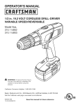
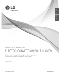
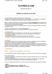
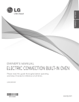
VL1
Security Video Light
Automatically record anyone who goes near your property
Product information
Product design and specifications are subject to change without notice.
This includes the main product specifications, software, software drives
and user’s manual. This User Manual is a general reference guide for the
product.
The product and accessories that come with your VL1 may be different
from those described in this manual. This is because some retailers
specify slightly different product versions and accessories to suit their
market requirements. Variations often include accessories such as
batteries, chargers, AC adaptors, memory cards, cables, carrying cases,
pouches and language support. Sometimes a retailer may specify a
unique colour, appearance or internal memory capacity. Please consult
your dealer for the exact product specification and included accessories.
The illustrations in this manual are for the purpose of explanation and
may differ from the actual design of your VL1. Any photographs shown
are for illustration purposes only and are not meant to represent the
quality that may be obtained by your product.
Securesight assumes no liability for any errors, omissions or
discrepancies in this user manual.
For user manual, firmware and driver updates please see our website.
Page No. 1
©Securesight 2009 E&OE Issue 1.0
Thank you for purchasing a Securesight VL1
This innovative self contained video and photo system will automatically
record images when movement is detected.
With its powerful 500W floodlight, the VL1 works day and night, giving
you peace of mind and protection for your property.
VL1 camera unit.
Shown without floodlight fitted.
©Securesight 2009 E&OE Issue 1.0
Page No. 2
Everything in the box?
Securesight VL1
Box contents
·
·
·
·
·
·
VL1 Digital Security Video Light
500w halogen bulb
USB lead for PC connection
SD memory card
Mounting screws
Warning sticker
If you are missing an item please contact your retailer.
IMPORTANT
The VL1 is designed for external use only
We recommend before installing your VL1 into position that you read the
full user guide to familiarise yourself with the controls, the operation
and settings before you mount the unit.
Page No. 3
©Securesight 2009 E&OE Issue 1.0
Get to know your equipment
©Securesight 2009 E&OE Issue 1.0
Page No. 4
Applications
The VL1 automatically records digital photos and videos when movement
is detected. It is a great way to protect your property and record
evidence of trespassers or unwanted visitors, day or night.
With a VL1 you can protect :·
·
·
·
·
·
·
·
·
·
Cars and driveways
Factories and offices
Homes and gardens
Sheds and garages
Outbuildings
Farms and yards
Stables and livestock
Building sites
Remote locations
Halls and club houses
Using the web cam feature, the VL1 can also be used for general
observation or for monitoring wildlife in your garden.
We trust our product will serve you well and are always pleased to
receive copies of your recordings, suggestions on how we can improve
our products and any new product ideas. For more information please
visit our web site at www.securesight.com
Page No. 5
©Securesight 2009 E&OE Issue 1.0
INDEX
VL1 Quick start guide
VL1 Full user guide
Understanding your VL1
How it works
Basic operation
SD Memory card
Recording format
Floodlight light level
Floodlight on time
Arming period
USB connection
VL1 mounting and the movement sensor
Advanced settings and functions
Menu structure – Main Setup
Menu structure – Image Setup
Main Setup Menu
Memory
Time / Date
Floodlight
Flicker
LED
PIR delay
USB
Default
©Securesight 2009 E&OE Issue 1.0
8
15
16
18
19
20
21
21
22
24
27
28
29
30
31
32
34
34
35
35
36
37
Page No. 6
INDEX continued
Image Setup Menu
Image mode
Photo setup
Resolution
Burst Mode
Burst Delay
Video Setup
Duration
Audio
Versatile image capture options
Understanding digital images
Digital video
Digital photos
SD card speed
Photo burst
Using your VL1 with a PC
Camera driver
Recording and uploading to the web
Your suggestions
Other Securesight products
Features and specifications
General information and safety
CE, ROHS and WEEE
Product support
Page No. 7
©Securesight 2009 E&OE Issue 1.0
38
39
39
39
40
41
41
41
42
43
43
44
48
48
49
49
50
51
51
52
53
54
Back cover
VL1 quick start guide
Your VL1 has been designed to be quick and easy to setup and operate
with factory settings that should suit most applications.
By default, when it detects movement, your VL1 will automatically
record 2 photographs followed by a 30 second video clip.
You can change these settings via the easy to use menu.
Please refer to the full guide for more information.
Basic setup is as easy as A,B,C.
A.
Fit the SD card and position the unit.
Fit the SD card into the slot
provided. Ensure you insert
the card with the metal
contact end in first and with
these contacts facing the
front (camera end) of the
unit.
The card should click into
place.
©Securesight 2009 E&OE Issue 1.0
Page No. 8
Carefully and without touching the glass of the bulb fit the halogen bulb
ensuring you secure the floodlight glass cover afterwards.
NOTE: Halogen bulbs get very hot and contamination from your skin can
cause the glass to break during operation.
We recommend positioning the unit between 3m and 4m on a sound wall
and angled towards the area of interest so that most traffic crosses the
PIR zones and triggers your VL1 to start recording.
Good results can also be obtained by positioning the VL1 higher and
facing down to the area of interest
See the section VL1 mounting and the movement sensor for details.
You can replace an existing outside light or undertake a new installation.
Page No. 9
©Securesight 2009 E&OE Issue 1.0
B.
Connect the mains supply.
Your VL1 requires mains power which should already be in place, if not
you will need to arrange for a competent and qualified person to install
the necessary cabling.
We recommend you use a switched circuit and that power is turned off
during installation.
Observe correct wiring – failure to do so will damage the unit and will
invalidate your warranty.
©Securesight 2009 E&OE Issue 1.0
Page No. 10
C.
Set the time and date
Turn on the power. The floodlight will come on for a short time. The LED
will flash rapidly as the VL1 arms. When this flashing stops, your VL1 will
be ready to record whenever movement is detected – day or night.
Try to return to your VL1 without triggering the motion sensor.
NOTE: You can only access the menu when the unit is not recording.
Below is the Normal screen of your VL1 display. It shows the software
version, the number of recordings, the Image Mode and the Photo
Resolution.
To access the menu, press the menu key,
display will light up and will show:-
– the
NOTE: When in a menu, if you do nothing for 20 seconds the software
will return to the normal screen.
Page No. 11
©Securesight 2009 E&OE Issue 1.0
You can press the Exit key
to exit a menu at any time without saving
any changes. Press the menu key
to enter the Main Setup menu.
Use the down arrow key
to move to the
Time/Date menu option and press the Menu key
to enter this menu. The display will change to show
new options for Time and Date setting :-
The real time clock is stopped when you set the date or time.
Thus for accuracy, you must always set the date before setting the time.
Select the Date option and press the Menu key
The format is DD:MM:YYYY
Use the up
and down
Press the Menu key
process for the year.
arrow keys to change the day setting.
to save and move to the month. Repeat this
©Securesight 2009 E&OE Issue 1.0
Page No. 12
.
When you have set the correct value for the year, pressing the Menu key
will save the date and return you to the Time and Date entry menu.
Now select the Time. The display will be similar to:The format is HH:MM:SS
Use the up
and down
keys to change the hour.
Press the Menu key
to move to the minute setting, change this then
the seconds. When you have set the correct value for the seconds,
pressing the Menu key
will save the time and start the clock running,
returning you to the Time / Date menu.
When you have set both date and time, press the Exit key
to exit the
menu or wait for approximately 20 seconds for the software to return to
the idle state.
NOTE: After leaving the menu and returning to the normal screen or
after a reset or power up, your VL1 will take approximately 1 minute to
arm. During this time the LED will flash rapidly. After this period, your
VL1 will begin recording when movement is detected.
You can now position your VL1 ready for action.
Page No. 13
©Securesight 2009 E&OE Issue 1.0
More information
Please read the rest of this guide to learn about changing your settings
and familiarising yourself with the operation of the VL1.
Access to our knowledge base, frequently asked questions and the ability
to log support cases can be found on our web site at
www.securesight.com
You can also register your product and download the camera driver
software to allow you to use your VL1 with a PC and as a web cam.
Also enter our competition to win back the purchase price of your unit.
For very urgent technical support you can contact UK support on
0906 5500 147
Monday to Friday 9am to 5pm.
Calls to this number are charged at £1 per minute from a BT landline
but may cost more from other operators.
©Securesight 2009 E&OE Issue 1.0
Page No. 14
VL1 full user guide
Understanding your VL1
The Securesight VL1 is a self-contained security system that
automatically records both video and digital photographs when
movement is detected.
Because it has a powerful 500w halogen floodlight the VL1 works both
day and night with the added deterrent of the light to ward off intruders.
Your VL1 can capture digital pictures up to 3 mega-pixels in resolution or
video clips with sound, up to 60 seconds long.
Recordings are stored to an SD memory card. A free SD card is supplied
with your VL1. You can use up to a 2Gb card allowing you to store over
5000 images.
You can recover recordings by retrieving your SD card and viewing the
contents using a PC or digital camera. Alternatively you can use a USB
cable to connect your PC directly to the VL1 and download recordings at
your convenience.
Your VL1 can also work as a web camera whilst full operation of the
floodlight is maintained. This allows you to view and make recordings to
your PC and even email or upload images to a web site.
Page No. 15
©Securesight 2009 E&OE Issue 1.0
How it works
IMPORTANT : Follow the Quick Start Guide to get your VL1 working.
Like a normal motion sensitive floodlight with a Passive Infra Red (PIR)
sensor, if the surrounding light level is low your VL1 floodlight will come
on when a warm object crosses its area of sensitivity.
Again, like a normal floodlight the light level at which your VL1 operates
and the time the light stays on are controlled by the LUX and Time
controls on the underside of the unit.
Unlike a normal floodlight, when motion is detected the VL1 will also
record video or photos and you can control the duration and number of
both.
The normal screen of your VL1.
©Securesight 2009 E&OE Issue 1.0
Page No. 16
Each video and photo is time and date stamped to provide evidence of
when the image was captured.
Your VL1 is fitted with a backup battery which should ensure the clock
continues to operate and all settings are kept in the event of a power
failure.
Whilst we recommend you check your equipment regularly especially
following a power cut you should only need to set up your VL1 once.
Page No. 17
©Securesight 2009 E&OE Issue 1.0
Basic operation
SD Memory card
Your VL1 will only allow you to record images if an SD card is fitted, or
you are operating it as a web camera and recording directly to your PC.
When no SD card is fitted the display will show No Card
If the unit attempts to record with no card present,
the LED will flash rapidly to warn you.
When you insert an SD card, the VL1 will read the contents of the card
and then display the number of recordings – in this example 160.
To avoid card reading problems or system freezes we
recommend you turn the power off when removing
and installing an SD card.
Fit your SD card into the slot provided. Ensure you insert the card with
the metal contact end in first and with these contacts facing the front
(camera end) of the unit. The card should click easily into place.
©Securesight 2009 E&OE Issue 1.0
Page No. 18
Recording format
Even if you insert a blank SD card, the VL1 will automatically create a
directory called DCIM and store your recordings in this directory.
This allows you to access the recordings using a PC or a digital camera.
Photographs are stored in the .jpeg format with the reference
SEC_XXXX.JPG where XXXX is the number for that recording
Videos are stored in the .avi format with the reference
SEC_XXXX.AVI where XXXX is the number for that recording
The SEC prefix denotes SECurity recording, allowing you to identify those
photos and videos taken by your VL1.
The VL1 will start the recording number based on the number of
recordings already on the SD card fitted e.g. if there are 10 recordings,
the next photo will be SEC_0011.JPG and so on.
If there are no recordings on the SD card, the VL1 will re-start numbering
at SEC_0001.JPG
Page No. 19
©Securesight 2009 E&OE Issue 1.0
Floodlight light level
The light level at which the floodlight comes on is controlled in two ways
and is set using the Floodlight menu from within the Main Setup.
Auto
The light is turned on when the camera
needs it and for as long as recording lasts.
LUX
The light is turned on based on the
setting of the LUX and Time control.
When set to LUX mode, you can adjust the light level at which the
floodlight comes on by changing the position of the LUX setting on the
underside of the VL1.
Turn the LUX control to the + setting if you want the floodlight to come
on in brighter conditions.
Turn the LUX control to the – setting if you want the floodlight to come
on only in very dark conditions.
In AUTO mode, the LUX and Time settings are
ignored and the camera decides when and for how
long the light is turned on.
©Securesight 2009 E&OE Issue 1.0
Page No. 20
Floodlight on time
When the Floodlight menu option is set to LUX the time that the
floodlight stays on for is determined by the TIME control of the base of
the VL1.
Move the TIME control to the – position to set it to minimum on time of
approximately 7 seconds.
Move the TIME control to the + position to set it to the maximum on time
of approximately 7 minutes.
When the Floodlight option is set to Auto, the on
time is controlled by the camera. If necessary,
the floodlight will come on and stay on for the
duration of recording regardless of the TIME
setting. It will go off approximately 5 seconds
after recording ends.
Arming period
Following power up or after you exit the main menu the LED on your VL1
will flash rapidly for approximately 1 minute before arming and
becoming ready to start recording.
If the LED mode is set to Flash, when the unit is ready to operate the
LED will begin flashing slowly every 5 seconds.
Page No. 21
©Securesight 2009 E&OE Issue 1.0
USB connection
You can connect your VL1 to your PC using the USB lead supplied.
Important : You must register your VL1 and install the camera driver
before connecting it to your PC. See the section Using your VL1 with a PC.
Each time you connect the USB lead to your PC, your VL1 will enter the
mode set in the USB menu within the Main Setup menu.
Note : Automatic recording by your VL1 stops
when it is connected to a PC.
PC Camera – Your VL1 will operate as a PC camera allowing you to view
and record images via your PC.
MSDC (Mass Storage Device Class) – You will be able to access your SD
card as a removable disc via your PC.
If your VL1 is recording when you connect the USB lead to your PC, it will
wait to complete the recording before giving you PC access. When you
remove the USB connection from your PC, your VL1 will automatically
reset.
©Securesight 2009 E&OE Issue 1.0
Page No. 22
Whilst the USB standard allows for only limited length cables, it is
possible to buy a USB extension cable up to 5m long. The USB menu
option allows you to leave a USB lead permanently connected to your
VL1 as the unit will behave the same way each time you connect your
computer. If set to MSDC you can access your recordings without having
to recover the SD card. If set to PC Camera you can use the VL1 as a web
camera and record directly to your PC (Additional software required).
When connected to your PC, the VL1 draws its power from the PC.
Therefore, in the event of a power failure and assuming your PC still has
power (like a laptop or a computer with an uninterruptible power
supply) your VL1 will continue to operate in either mode.
When mains power is connected and your VL1 is operating as a PC
camera the floodlight on your VL1 will continue to operate
independently, turning on when movement is detected. In this mode,
the light level at which the floodlight comes on is determined by the LUX
setting.
Should power fail whilst your VL1 is connected to a PC, the unit will
continue to work as a PC camera or removable disc drive, but the
floodlight will stop operating.
NOTE: When you disconnect the VL1 from your PC, the VL1 will reset.
Page No. 23
©Securesight 2009 E&OE Issue 1.0
VL1 mounting and the movement sensor
Passive Infra Red (PIR) sensors detect changes in infra-red radiation in
the form of heat given off by objects such as people, cars and animals.
The larger the object the more infra-red it emits. Your VL1 has an angle
of sensitivity of approximately 65 degrees and approximately 9m range.
To focus the
energy to its
sensor your VL1
uses a Fresnel lens.
This divides the
area into a number
of zones, both
vertical and
horizontal.
PIR sensors detect
moving hot objects
as they cross zones.
Thus they are most
sensitive to
movement across
the area of
sensitivity and
least sensitive to
movement towards
the sensor.
©Securesight 2009 E&OE Issue 1.0
Page No. 24
We therefore recommend that you position your VL1 at a height of 3 - 4
meters and angled towards the area of interest so that most traffic
crosses the zones and triggers your VL1 to start recording.
The PIR sensor detects
the difference between
objects and ambient air
temperature and will
only trigger when it
detects a hot object
moving across its zones.
OK
BETTER
Page No. 25
Because of this the area
of sensitivity will vary
with changes in
temperature and the size
of the object. Your VL1
will become more
sensitive in winter and at
night when the
difference between the
hot object and the
ambient air temperature
is greatest, with
sensitivity reducing in
summer and during the
day when the difference
is less.
©Securesight 2009 E&OE Issue 1.0
Although not necessary, positioning of your VL1 to obtain the desired
field of view is made quicker using a laptop PC and a USB lead. Using
appropriate software on the laptop you can view images from your VL1
and adjust its position to get the field of view you require.
NOTE: Before using your VL1 with a
PC you must download the camera
driver from our website.
Having installed the camera driver,
set the USB mode on your VL1 to
PC Camera and connect the USB
lead. The computer will indicate
that it has found new hardware and
will configure the device.
Using one of the many free web
cam programs available should
allow you to use your PC to view
images from your VL1.
©Securesight 2009 E&OE Issue 1.0
Page No. 26
Advanced settings and functions
The VL1 works straight from the box but it also has a simple and easy to
operate menu system so you can change any settings. When you first
power it the floodlight will come on for a short time and the LED will
flash rapidly as the VL1 arms. When this rapid flashing stops, your VL1
will be ready to record whenever movement is detected – day or night.
The normal screen on your VL1 display will show the number of
recordings, the Image Mode and the Photo Resolution settings. When
recording it will say Recording on the screen. You cannot access the
menu of your VL1 whilst it is recording.
To enter and explore the menu, press the Menu key
on the base of the VL1. Press the Exit key
exit any menu at any time without saving your
changes. Use the Up
navigate and the Menu key
and Down
arrow keys to
to enter a menu or save a setting.
The menu structures are described below along with details of each
setting to help you understand its function.
The two main menus are
·
·
Main Setup
Image Setup
Page No. 27
©Securesight 2009 E&OE Issue 1.0
to
MENU STRUCTURE – Main Setup
©Securesight 2009 E&OE Issue 1.0
Page No. 28
MENU STRUCTURE – Image Setup
Page No. 29
©Securesight 2009 E&OE Issue 1.0
Main Setup menu
Press the menu key
Use the up
to enter the Main Setup menu.
and down
arrow keys to select a menu option and the
Menu key
to enter that option. You can press the Exit key
a menu at any time without saving any changes.
to exit
NOTE: When in a menu, if you do nothing for 20 seconds the software
will return to the normal screen.
NOTE: When you exit the menus and return to the normal screen your
VL1 will take approximately 1 minute to arm. During this time the LED
will flash rapidly. After this period, each time the VL1 detects movement
it will begin recording and the light will come on if appropriate.
©Securesight 2009 E&OE Issue 1.0
Page No. 30
Memory
The Memory menu option allows you to Delete all the contents of your
SD memory card.
With the card fitted, select the Memory option from within the Main
Setup menu and press the Menu key
the display will show
Delete SD Card
Press the Menu key
to delete all files on the card.
The display will go blank for a few seconds before returning to the menu.
If no card is fitted the display will show
No Card
Page No. 31
©Securesight 2009 E&OE Issue 1.0
Time / Date
This menu offers you two options, Time and Date and enables you to set
either.
Use the down arrow key
press the Menu key
to move to the Time/Date menu option and
to enter this menu. The display will show:-
IMPORTANT : While setting the date, operation of the real time clock is
halted. Therefore the clock will lose time depending on how long you
remain within the date setting menu. You must therefore set the date
before setting the time.
Select the Date option and press the Menu key
.
The display will be similar to the screen below.
The format is DD:MM:YYYY
Use the up
and down
arrow keys to change
the day setting. Press the Menu key
©Securesight 2009 E&OE Issue 1.0
to save.
Page No. 32
Repeat the process for the month and year. When you have set the
correct value for the year, pressing the Menu key
and return you to the Time and Date entry menu.
will save the date
Now select the Time. The display will be similar to the screen below.
The format is HH:MM:SS
Use the up
and down
keys to change the hour setting.
Press the Menu key
to move to the minute setting and then seconds.
When you have set the correct value for the seconds, pressing the Menu
key
will save the time and start the clock running and return you to
the Time / Date menu.
Page No. 33
©Securesight 2009 E&OE Issue 1.0
Floodlight
Enter this menu to choose between Auto and Lux.
In Auto mode, the camera decides when and for how the long the light
comes on. The on time will match the duration of recording plus
approximately 5 seconds.
In LUX mode, the level of light is measured by a photo sensor and the
light comes on depending on the setting of the LUX control on the base
of the VL1. In LUX mode the light on time is controlled by the TIME
setting.
Flicker
This setting enables the camera circuitry to compensate for the effect of
mains flicker visible through electric light.
Set this according to your countries mains frequency. The choice is
between 50Hz (UK, Europe and most of the world) or 60Hz (USA and
Japan).
©Securesight 2009 E&OE Issue 1.0
Page No. 34
LED
This menu controls the operation of the LED indicator on the front of the
VL1. There are three choices Flash, PIR, Off.
Regardless of this setting, the LED will flash
rapidly whilst your VL1 is arming or if movement
is detected but no SD card is fitted.
Select Flash mode and the LED will flash at approximately 5 seconds
intervals and come on continuously during recording.
Select PIR mode and the LED will only come on continuously during
recording (After the PIR motion sensor has been triggered).
Select OFF mode and the LED will be off during normal operation.
PIR delay
This option allows you to set a delay which causes the VL1 to wait after
being triggered before it will respond to a trigger again. The delay
options are 0 seconds (no delay) through to 120 seconds (3 minutes).
This can be useful to minimise recordings.
Page No. 35
©Securesight 2009 E&OE Issue 1.0
USB
This option allows you to select how the VL1 behaves when connected to
a PC via a USB cable.
PC Camera
The VL1 will operate as a web camera
MSDC
The VL1 will operate as an external disc drive
Once the USB mode is set, whenever your VL1 is connected to a PC it will
always behave in the same way.
Note : Automatic recording stops when your VL1 is connected to a PC.
©Securesight 2009 E&OE Issue 1.0
Page No. 36
Default
This single option allows you to return the VL1 to its default settings.
Default settings are:Floodlight
Flicker
LED
PIR delay
Image mode
Photo Resolution
Photo Burst mode
Photo Burst delay
Video duration
Audio recording
USB mode
LUX
50 Hz
Flash
0
Combo
2 Megapixel
2 pictures
Low
30 seconds
On
PC Camera
You are asked to confirm before resetting your VL1 back to its factory
default settings.
NOTE : Even in the event of a power failure your settings will be
retained and the system clock will continue to run which should ensure
you never have to change anything once you have setup your VL1.
Page No. 37
©Securesight 2009 E&OE Issue 1.0
Image Setup menu
Image Mode
The menu allows you to select how the camera system behaves when the
PIR sensor is triggered.
Photo
The VL1 will capture between 1 to 10 photos. The number and
time between them is set in the Photo Setup menu.
Video
The VL1 will capture a video clip from 10 seconds to 60 seconds
long. The duration is set in the Video Setup menu.
Combo Combination mode - The VL1 will capture a burst of photos
followed by a video clip matching the settings in the Photo and
Video setup menus.
The Photo and Video settings allow you to create various combinations to
suit your requirements.
Enter the menu and use the up
and down
keys to select the way
you would like your VL1 to operate. Press the Menu key
©Securesight 2009 E&OE Issue 1.0
to save.
Page No. 38
Photo Setup
This menu allows you to control the way the VL1 takes photos.
Sub-menus are:·
·
·
Resolution
Burst Mode
Burst Delay
Resolution
This allows you to set the resolution of the photo stored by the VL1.
High
Normal
Medium
Low
3 Megapixel
2 Megapixel
1.3 Megapixel
0.5 Megapixel
2048 x 1536
1200 x 1600
1280 x 1024
800 x 600
Burst Mode
This determines how many photos the VL1 takes when triggered.
High
Normal
Medium
Low
10
5
2
1
Page No. 39
©Securesight 2009 E&OE Issue 1.0
Burst Delay
This forces an additional delay between photo capture, allowing you to
capture images over a longer period of time. The delay varies from 0
seconds to 10 seconds.
High
Normal
Medium
Low
10 sec
5 sec
1 sec
0 sec
By default there is always a small delay between taking photos as it
takes a small amount of time for your VL1 to store each photo. This is
normal for digital cameras and the Burst Delay setting does not control
the exact time between photos, it increases that time. The actual delay
is determined by several factors described in the section Understanding
Digital Images.
©Securesight 2009 E&OE Issue 1.0
Page No. 40
Video Setup
There are two sub-menus to control the video operation of the VL1.
·
·
Duration
Audio
Duration
This sets the length of your video clip. Set this to suit your application.
High
Normal
Medium
Low
60 seconds
30 seconds
20 seconds
10 seconds
Audio
This option allows you to turn on and off the audio recording for your
video clips. Recordings without audio take up less memory space and
allow you to store more on a given size of memory card.
Page No. 41
©Securesight 2009 E&OE Issue 1.0
Versatile image capture options
Assume you have made the following settings:Photo Resolution
Photo Burst
Photo delay
Low
2 pics
Low
Video Duration
Audio
10
On
If you change the Image Mode to Photo, when triggered the VL1 will take
two low resolution photos approximately 3 seconds apart.
If you now change the Image Mode to Video, when triggered the VL1 will
record a 10 second video with sound.
If you then change Image Mode to Combo, when triggered the VL1 will
take 2 low resolution photos then record a 10 second video with audio.
Once configured to your requirements, when triggered the VL1 will
behave based on the settings you have made in the menus. Your settings
will not change unless you change them or select the Default option from
the Setup Menu.
Video and Photo settings are independent of each other, giving you the
ability to create the combination which best suits your application or to
simply record one or the other.
©Securesight 2009 E&OE Issue 1.0
Page No. 42
Understanding digital images – Additional reading
Your VL1 allows you to take either videos or photos or both. The choice
depends on what images you are trying to record.
The VL1 uses a single 1.3 Mega-pixel (Mp) image sensor to capture both
photos and video. This sensor has 1280 unique cells horizontally and 1024
cells vertically. In total it has 1280 x 1024 = 1310720 pixels or 1.3Mp
Each cell is capable of measuring light
levels and colour. The camera lens
focuses the image onto the image
sensor and the camera reads the light
and colour level of every cell. It
stores this information as a digital
picture or frame.
Digital video
A digital video is a succession of such digital frames played to the viewer
at a certain rate – frames per second. The human eye can distinguish up
to 20 frames per second but anything faster gives the illusion of full
animation. The faster the frame rate, the smoother the video but the
more storage it requires. Similarly the larger the picture size the more
storage is required. The VL1 will automatically decide on the best frame
rate for each recording.
Page No. 43
©Securesight 2009 E&OE Issue 1.0
To store video in a practical way and maximise the number of clips that
can be stored on a single SD memory card the VL1 compresses video in to
frames that match the video standard of 320 x 240 pixels or QVGA. Video
and photos still have the same field of view but video offers considerably
lower resolution than a photo.
Video is ideal for capturing action but photos are better for recognition.
Comparison of a
320 x 240 video frame
to 800 x 600 photo.
Digital Photos
Whilst digital photos cannot capture the action, they are very good for
providing evidence for identification of people.
Unlike digital video where each frame or picture must be small in size to
be recorded and stored quickly, because speed is not so important when
storing a photo they can be much larger and contain more pixels and
hence more information.
©Securesight 2009 E&OE Issue 1.0
Page No. 44
In digital images, the more pixels the better the resolution but the larger
the file size and hence the more memory needed to store each picture.
The combo mode on your VL1 gives you the best of both worlds, a better
resolution photo for evidence with a great video to capture action.
Like all digital cameras, the VL1 uses a method called interpolation to
obtain images that are higher in resolution than the natural resolution of
its image sensor. Interpolation effectively inserts additional pixels of
information into an image and uses clever software to guess what colour
and brightness that pixel should be based on those pixels around it.
The more pixels a digital photo has, the greater resolution it offers.
Because more pixels means more information, a higher resolution will be
larger and therefore take longer to store.
This picture
shows the
same scene
and the same
view but
compares
the size of a
0.5Mp image
against a
3Mp image.
Page No. 45
©Securesight 2009 E&OE Issue 1.0
Digital photo resolution is based on 72 dots per inch (dpi). The first
photo above is 800 x 600 pixels in size (0.5Mp) and would therefore be
just over 11 inches wide if printed without any adjustment. The second
is picture of the same scene is 2048 x 1536 pixels (3Mp), nearly 2.5 times
the size.
Although both photos are of the same scene, the second has considerably
more pixels, in fact over 6.5 times more and hence offers much higher
resolution, allowing you to see more detail in the picture.
If we scale the lead figure in both photo and compare with a video still it
is easy to see that more pixels gives more resolution and better
recognition.
Video 320x240
Photo 800x600 0.5Mp Photo 2048x1536 3Mp
©Securesight 2009 E&OE Issue 1.0
Page No. 46
However, remember the amount of detail you can resolve in an image
depends on how close the object of interest is to the VL1.
Your VL1 can record photos in the following resolutions
High
Normal
Medium
Low
3 Megapixel
2 Megapixel
1.3 Megapixel
0.5 Megapixel
2048 x 1536
1200 x 1600
1280 x 1024
800 x 600
Whilst high resolution photos are great, because they contain so much
more information (more pixel data) their file sizes are much larger and
as such they use up more memory on the SD memory card.
Your VL1 can record to an SD card up to 2Gb in size. This size of card
gives the capacity to store over 5000 2Mp photos before the VL1 starts to
overwrite the oldest recordings.
Page No. 47
©Securesight 2009 E&OE Issue 1.0
SD card speed
The size of a photo also affects the time it takes for the VL1 to write the
data to an SD card. Different cards have different write speeds measured
in megabits per second (Mb/s). The faster the card, the less time it takes
for any given size of file to be written to it.
Photo Burst
As discussed above, it takes a small amount of time for your VL1 to store
each photo. The faster the SD card, the shorter this time will be.
Similarly, the smaller the file size (e.g. a low resolution photo) the
shorter the write time. This is normal for digital cameras.
As the amount of detail in the picture will also affect file size there is no
absolute time for how quickly your VL1 can take multiple photos but to
achieve the shortest time possible between photos when using burst
mode set the Burst Delay to the minimum, set the Photo Resolution to
Low and use a very fast SD memory card.
Similarly, taking bursts of high resolution photos will slow your VL1 down
and can take up to 5 seconds between shots. This is normal.
©Securesight 2009 E&OE Issue 1.0
Page No. 48
Using your VL1 with a PC
Important : You must install a camera driver before connecting your VL1
to your PC otherwise it will not work.
When you connect your VL1 to a PC using a USB lead you can use the VL1
as a web camera or directly access the SD as a removable disc drive.
Camera driver
Your VL1 will not work with your PC unless you first install the camera
driver. This is a small piece of software that you can download from the
registration page of our web site at
www.securesight.com/registration
You will need to enter the serial number of your VL1. This is located on
the side of the junction box.
Follow the on screen instructions to download and install the driver. The
VL1 is designed to work with a PC operating Windows XP, please see our
web site for compatibility with other computers and operating systems.
Once installed, connect your VL1 to your PC via the USB lead provided. It
is possible to use a 5m USB extension lead to enable permanent access to
your VL1.
Page No. 49
©Securesight 2009 E&OE Issue 1.0
Recording and uploading to the web
To use your PC to both record photos and video and to email or upload
these to the web, we suggest software by Visiongs available to
download at www.visiongs.de
Please note, that as long as power is provided, your VL1 will continue to
operate as an automatic floodlight whilst in PC camera mode, offering
you the best external web cam solution.
The Visiongs software allows you to carry out the following using your
VL1
·
·
·
·
·
·
·
·
·
Scheduled or timed image/video capture to your PC hard disc
Scheduled or timed image/video upload to the web
Time and date stamp on all recordings
Video motion detection with selective masks
Automatic image emailing
FTP image upload
Image colour filtering
Live streaming to your web site
Plus many more features
A free version is available with some restrictions whilst a professional
version is very reasonably priced with no restrictions on performance.
©Securesight 2009 E&OE Issue 1.0
Page No. 50
Your suggestions
Please let us know how you feel we could improve the VL1 or any of our
products. Every month, we offer those who respond the opportunity to
win a full refund on their purchase.
Please visit the customer feedback section at www.securesight.com
Also, we welcome any new product ideas. For any original and new
product idea which we subsequently take into production we pay
£500* so it’s worth taking the time to make your suggestion.
See www.securesight.com for details. *Terms and conditions apply.
Other Securesight products
Visit our website to find out more about Securesight products including:AP08
DV1
Alarm padlock
Digital door
shock and
viewer and
motion sensitive recorder
With 110dB siren
Page No. 51
©Securesight 2009 E&OE Issue 1.0
Features and specifications
Colour CMOS Image Sensor 1.3M pixels.
Max Resolution: 3.0M pixels, 2048x1536 pixels by hardware interpolation
Photo burst options : 1 pic, 2 pic, 5 pic, 10 pic
Video durations : 10 sec, 20 sec, 30 sec, 60 sec
Image performance for video stream: Up to 25fps at 320 x 240 pixels
Microphone for audio recording on videos
Backlit LCD dot matrix display for ease of use and programming
Built in SD card slot for SD memory card up to 2Gb
LED for operational status with 3 modes – Flash, PIR, Off
Automatic exposure control, white balance and sharpness
Time & date stamp on both photo and video
Focusing: 1.5m (minimum) to Infinity
Effective viewing angle: Approximately 48 degrees
Built in USB socket for PC camera or external disk operation
Interface type: USB 1.1 for use with PC computers running Windows XP
Photo format: .jpg
Video format: .avi
PIR detection angle approximately 65 degrees and detection range up to 9M.
Lux control for floodlight on light level
Time control for floodlight on time
Auto option for camera control of lux level and on time
Powered by AC 110V or 220V (subject to requirement).
Floodlight bulb is 500W, type R7S
Product measurements: W185 x H300 x D135mm. Weight 0.9Kg.
Operating Environment:
14 to 104 deg F (-10 to 40 deg C).
20-85% relative humidity, non-condensation.
©Securesight 2009 E&OE Issue 1.0
Page No. 52
General information and safety
Storage conditions: -20ºC to 55ºC, 20-85% R.H., non-condensing
Special care instructions: The VL1 is rated IP44 and designed to be
weather resistant. Never attempt to immerse the unit in water or any
other liquid. This will damage the unit and void your warranty. Use a
soft lens cloth for cleaning lens. Avoid touching lens with fingers.
Remove dirt or stains with a soft cloth dampened with water or mild
detergent. Keep the VL1 in a dry and cool dust-free environment or
container when it is NOT used.
Do not open the VL1 for unauthorized service. This could cause serious
damage to the unit and will void your warranty. This VL1 is a precision
electronic device. Do not attempt to service this camera yourself, as
opening or removing covers may expose you to dangerous voltage points
or other risks.
Do not touch the floodlight when the power is on, it is extremely hot.
Changes to building regulations
As of January 1st 2005, changes to the Building regulations in the UK affected
domestic electrical installations in England and Wales. You don’t need to be a
qualified electrician to make changes to your home’s electrical system, but the
work must be done in accordance with the standards in the Regulations.
To find out more visit http://www.communities.gov.uk/electricalsafety
Page No. 53
©Securesight 2009 E&OE Issue 1.0
CE, ROHS and WEEE
This device has CE approval and to the best of our knowledge is in
accordance with the applicable directives 89/336/EEC Electromagnet
Compatibility (as amended) EMC
EN 55022: 1998+A1: 2001+A2: 2003 Class B
EN 55024: 1998+A1: 2001+A2: 2003
EN 61000-3-2: 2000+A2: 2005
EN 61000-3-3: 1995+A1: 2001+A2: 2005
This statement confirms that to the best of our knowledge this product
complies with the European Union’s directive 2002/95/EC, Restrictions
of Hazardous Substances (”RoHS” directive) and similar regulations that
may be adopted by other countries. RoHS directive becomes valid on Jul
1 2006 in the member states of European Union. It states that all new
electrical and electronic equipment put on the market within the
member states must not contain certain hazardous materials.
This symbol on the product or on its packaging
indicates that the product must not be disposed of
with normal household waste. Instead, it is your
responsibility to dispose of your waste equipment by
arranging to return it to a designated collection
point for the recycling of waste electrical and
electronic equipment. By separating and recycling
your waste equipment at the time of disposal you will help to conserve
natural resources and ensure that the equipment is recycled in a manner
that protects human health and the environment.
©Securesight 2009 E&OE Issue 1.0
Page No. 54
Product support
Access to our knowledge base, frequently asked questions and the ability
to log support cases can be found on our web site at
www.securesight.com
You can also register your product and download the camera driver to
allow you to use your VL1 with a PC and as a web camera.
Also enter our competition to win back the purchase price of your unit.
For very urgent technical support you can contact UK support on
0906 5500 147
Monday to Friday 9am to 5pm.
Calls to this number are charged at £1 per minute from a BT landline
but may cost more from other operators